1
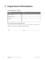
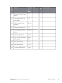
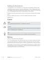
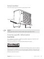
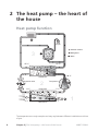
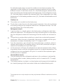
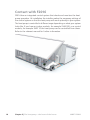
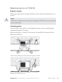
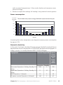
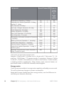
User manual
NIBE™ F2016
UK 1x230V
LEK
Air/water heat pump
UHB GB 1244-2
031884
Table of Contents
1 Important information
2
Installation data
Safety information
Serial number
Country specific information
F2016 - An excellent choice
2
4
5
5
7
2 The heat pump – the heart of the house
Heat pump function
Contact with F2016
Maintenance of F2016
3 Disturbances in comfort
8
8
10
11
16
Troubleshooting
16
4 Technical data
5 Glossary
19
20
Item register
Table of Contents |
24
NIBE™ F2016
1
1 Important information
Installation data
Product
F2016
Serial number
Installation date
Installer
Serial number must always be given
Certification that the installation is carried out according to instructions in
NIBE's installer manual and applicable regulations.
Date
2
__________________
Chapter 1 | Important information
Signed
_________________________
NIBE™ F2016
Chan- Name
nel
Default Set
settings
A1
Communications address
1
A3
Connection diff. return temp.
4 °C
A4
Start interval compressor
20 min
A5
Balance temperature
0 °C
A6
Time delay addition
relay
120 min
A7
Stop temperature
-15 °C
A8
Min. interval between 60/50
defrosting
/45
A9
Start defrosting
✔ Accessories
+1 °C
A10 Stop defrosting
+10 °C
A11 Longest defrosting
7 min
Chapter 1 | Important information
NIBE™ F2016
3
Safety information
This appliance is not intended for use by persons (including children) with
reduced physical, sensory or mental capabilities, or lack of experience and
knowledge, unless they have been given supervision or instruction concerning
use of the appliance by a person responsible for their safety.
Children should be supervised to ensure that they do not play with the appliance.
Rights to make any design or technical modifications are reserved.
©NIBE 2012.
Symbols
NOTE
This symbol indicates danger to machine or person.
Caution
This symbol indicates important information about what you should observe
when maintaining your installation.
TIP
This symbol indicates tips on how to facilitate using the product.
Marking
F2016 is CE marked and fulfils IP24.
The CE marking means that NIBE ensures that the product meets all regulations that are placed on it based on relevant EU directives. The CE mark is
obligatory for most products sold in the EU, regardless where they are made.
IP24 means that the product is secure against penetration by objects with a
diameter larger than or equivalent to 12.5 mm and that the product is protected against drops from all directions.
4
Chapter 1 | Important information
NIBE™ F2016
Serial number
The serial number can be found on the product's foot.
LEK
6HULDO QXPEHU
Caution
Always give the product's serial number when reporting a fault.
Country specific information
Great Britain
This installation is subject to building regulation approval, notify the local
Authority of intention to install.
Use only manufacturer’s recommended replacement parts.
Nibe is a licensed member of the Benchmark Scheme which aims to improve
the standards of installation and commissioning of domestic heating and hot
water systems in the UK and to encourage regular servicing to optimise safety,
efficiency and performance.
Chapter 1 | Important information
NIBE™ F2016
5
Benchmark is managed and promoted by the Heating and Hotwater Industry
Council. For more information visit www.centralheating.co.uk
Warranty and insurance information
Thank you for installing a new NIBE heat pump in your home.
NIBE heat pumps are manufactured in Sweden to the very highest standard
so we are pleased to offer our customers a comprehensive guarantee.
The product is guaranteed for 24 months for parts and labour from the date
of installation or 33 months from the date of manufacture, whichever is the
shorter.
The NIBE guarantee is based on the unit being installed and commissioned
by a NIBE accredited installer, serviced every year and the Benchmark documents completed. Where this condition is not met, any chargeable spare
parts or components issued within the applicable guarantee period still benefit
from a 12 month warranty from the date of issue by the manufacturer.
We recommend the installer completes and returns as soon as possible, your
guarantee registration card or completes the guarantee form on the NIBE
website www.nibe.co.uk.
Please ensure that the installer has fully completed the Benchmark Checklist
in the end of the Installation Instructions supplied with the product and that
you have signed to say that you have received a full and clear explanation of
its operation. The installer is legally required to complete a commissioning
checklist as a means of complying with the appropriate Building Regulations
(England and Wales).
All installations must be notified to Local Area Building Control either directly
or through a Competent Persons Scheme. A Building Regulations Compliance
Certificate will then be issued to the customer who should, on receipt, write
the Notification Number on the Benchmark Checklist.
This product should be serviced regularly to optimise its safety, efficiency and
performance. The service engineer should complete the relevant Service Record
on the Benchmark Checklist after each service.
The Benchmark Checklist may be required in the event of any warranty work
and as supporting documentation relating to home improvements in the
optional documents section of the Home Information Pack.
6
Chapter 1 | Important information
NIBE™ F2016
F2016 - An excellent choice
F2016 is an air/water heat pump specially developed for the Nordic climate,
which utilises the outside air so there is no need for bore holes or coils in the
ground.
The heat pump is intended for connection to water borne heating systems
and can both heat hot water effectively at high outdoor temperatures and
give a high output to the heating system at low outdoor temperatures.
If the outdoor temperature drops to a level below the stop temperature all
heating must then occur with external additional heat.
Excellent properties for F2016:
႑
Efficient scroll compressor
Efficient scroll compressor that operates at temperatures down to -15 °C.
႑
Intelligent control
Integrated intelligent control for optimum control of the heat pump.
F2016 is started by a start signal from another unit (VVM 300 for example)
or thermostat.
႑
Fan
With the exception of F2016-6 kW (which only has one fan speed) F2016
has an automatic 2-step capacity control of the fan.
႑
Long service life
The material has been chosen for a long service life.
႑
Many possibilities
F2016 can also be used together with most electric boilers, oil boilers or
similar.
Chapter 1 | Important information
NIBE™ F2016
7
2 The heat pump – the heart of
the house
Heat pump function
H
+HDWLQJ PHGLXP
5HIULJHUDQW
I
%ULQH
45 °C
55 °C
G
E
80 °C
&RQGHQVHU
Kondensor
Expansionsventil
([SDQVLRQ
YDOYH
F
0 °C
Kompressor
&RPSUHVVRU
Förångare
(YDSRUDWRU
D
5 °C
C
B
-3 °C
+HDW VRXUFH
A
2 °C
The temperatures are only examples and may vary between different installations and time
of year.
8
Chapter 2 | The heat pump – the heart of the house
NIBE™ F2016
An air/water heat pump can use the outdoor air to heat a property. The
conversion of the outdoor air's energy to property heating occurs in three
different circuits. In the brine circuit, (1) , free heat energy is retrieved from
the surroundings and transported to the heat pump. In the refrigerant circuit,
(2) , the heat pump increases the retrieved heat's low temperature to a high
temperature. In the heating medium circuit, (3) , the heat is distributed around
the house.
A
B
C
D
E
F
G
H
Outdoor air
The outdoor air is sucked into the heat pump.
The fan then routes the air to the heat pump’s evaporator. Here, the air releases
the heating energy to the refrigerant and the air's temperature drops. The cold
air is then blown out of the heat pump.
Refrigerant circuit
A gas circulates in a closed system in the heat pump, a refrigerant, which also
passes the evaporator. The refrigerant has a very low boiling point. In the evaporator the refrigerant receives the heat energy from the outdoor air and starts to
boil.
The gas that is produced during boiling is routed into an electrically powered
compressor. When the gas is compressed, the pressure increases and the gas's
temperature increases considerably, from 5 °C to approx. 80°C.
From the compressor, gas is forced into a heat exchanger, condenser, where it
releases heat energy to the heating system in the house, whereupon the gas is
cooled and condenses to a liquid form again.
As the pressure is still high, the refrigerant can pass an expansion valve, where
the pressure drops so that the refrigerant returns to its original temperature. The
refrigerant has now completed a full cycle. It is routed to the evaporator again
and the process is repeated.
Heat medium circuit
The heat energy that the refrigerant produces in the condenser is retrieved by
the climate system's water, heating medium, which is heated to 55 °C (supply
temperature).
The heating medium circulates in a closed system and transports the heated water's heating energy to the house water heater and radiators/heating coils.
The temperatures are only examples and may vary between different installations and time
of year.
Chapter 2 | The heat pump – the heart of the house
NIBE™ F2016
9
Contact with F2016
F2016 has an integrated control system that checks and monitors the heat
pump operation. At installation the installer makes the necessary settings of
the control system so that the heat pump will work optimally in your system.
The heat pump is controlled in different ways depending on what your system
looks like. If you have an indoor module, for example VVM 300, or a control
module, for example SMO 10 the heat pump can be controlled from these.
Refer to the relevant manual for further information.
10
Chapter 2 | The heat pump – the heart of the house
NIBE™ F2016
Maintenance of F2016
Regular checks
When your heat pump is located outdoors some external maintenance is required.
NOTE
Insufficient oversight can cause serious damage to F2016 which is not covered
by the guarantee.
Checking grilles
Check that the inlet grille is not clogged by leaves, snow or anything else
regularly throughout the year.
Pay extra attention in event of high winds or snowfall that may cause the
grille to be blocked.
LEK
Prevent snow building up and covering the grille on F2016.
LEK
Keep free of snow and/or ice.
Chapter 2 | The heat pump – the heart of the house
NIBE™ F2016
11
Cleaning the outer casing
If necessary the outer casing can be cleaned using a damp cloth.
Care must be exercised so that the heat pump is not scratched when cleaning.
Avoid spraying water into the grilles or the sides so that water penetrates
into F2016. Prevent F2016 coming into contact with alkaline cleaning agents.
Condensation drain pan and condensation water pipe
The condensation drain pan and condensation water/drain pipe may require
cleaning from leaves or similar during the year.
Cleaning
1. Use the safety switch to cut the incoming electrical supply.
2. Release the trough using the quick release catches on the left and right
front edges. Keep in position at the rear edge without stretching the
power cable.
3. Clean drain pans and condensation water pipe/drains.
4. Reinstall the trough using the removal method in reverse order (see point
2).
5. Switch on the safety switch again.
In event of long power cuts
In the event of prolonged power failures it is recommended that the part of
the heating system located outdoors is drained. Your installer has fitted a
shutoff and a drain valve to facilitate this. Ask you installer if you are unsure.
Saving tips
Your heat pump installation produces heat and/or hot water. This occurs via
the control settings you made.
Factors that affect the energy consumption are, for example, indoor temperature, hot water consumption, the insulation level of the house and whether
the house has many large window surfaces. The position of the house, e.g.
wind exposure is also an affecting factor.
Also remember:
႑
12
Open the thermostat valves completely (except in the rooms that are to
be kept cooler for various reasons, e.g. bedrooms). The thermostats slow
the flow in the heating system, which the heat pump wants to compensate
Chapter 2 | The heat pump – the heart of the house
NIBE™ F2016
with increased temperatures. It then works harder and consumes more
electrical energy.
႑
Reduce or adjust the settings for heating in any external control systems.
Power consumption
RI DQQXDO
FRQVXPSWLRQ
7KH DLUZDWHU KHDW SXPS
V HQHUJ\ GLVWULEXWLRQ VSUHDG DFURVV WKH \HDU
25%
20%
15%
10%
5%
0%
-DQ
jan
)HE
feb
0DU
mars
$SULO
april
0D\
maj
-XQH
juni
-XO\
juli
$XJ
aug
6HS
sep
2FW
okt
1RY
nov
'HF
dec
0RQWK
Increasing the indoor temperature one degree increases power consumption
by approx. 5%.
Domestic electricity
In the past it has been calculated that an average Swedish household has an
approximate annual consumption of 5000 kWh domestic electricity/year. In
today's society it is usually between 6000-12.000 kWh/year.
Equipment
Flat-screen (Operation: 5 h/day, Standby: 19
h/day)
Digital box (Operation: 5 h/day, Standby: 19
h/day)
DVD (Operation: 2 h/week)
TV games console (Operation: 6 h/week)
Normal Output (W) Approximate
annual
consumption
(kWh)
Operation Standby
200
2
380
11
10
90
15
160
5
2
45
67
Chapter 2 | The heat pump – the heart of the house
NIBE™ F2016
13
Equipment
Radio/stereo (Operation: 3 h/day)
Computer incl. screen (Operation: 3 h/day,
standby 21 h/day)
Bulb (Operation 8 h/day)
Spot light, Halogen (Operation 8 h/day)
Cooler (Operation: 24 h/day)
Freezer (Operation: 24 h/day)
Oven, hob (Operation: 40 min/day)
Oven (Operation: 2 h/week)
Dishwasher, cold water connection (Operation
1 time/day)
Washing machine (Operation: 1 time/day)
Tumble drier (Operation: 1 time/day)
Vacuum cleaner (Operation: 2 h/week)
Engine block heater (Operation: 1 h/day, 4
months a year)
Passenger compartment heater (Operation: 1
h/day, 4 months a year)
Normal Output (W) Approximate
annual
consumption
(kWh)
40
100
1
2
50
120
60
20
100
120
1500
3000
2000
-
175
55
165
380
365
310
730
2000
2000
1000
400
-
730
730
100
50
800
-
100
These values are approximate example values.
Example: A family with 2 children live in a house with 1 flat-screen TV, 1 digital box, 1 DVD player, 1 TV games console, 2 computers, 3 stereos, 2 bulbs
in the WC, 2 bulbs in the bathroom, 4 bulbs in the kitchen, 3 bulbs outside,
a washing machine, tumble drier, fridge, freezer, oven, vacuum cleaner, engine block heater = 6240 kWh domestic electricity/year.
Energy meter
Check the accommodation's energy meter regularly, preferably once a month.
This will indicate any changes in power consumption.
Newly built houses usually have twin energy meters, use the difference to
calculate your domestic electricity.
14
Chapter 2 | The heat pump – the heart of the house
NIBE™ F2016
New builds
Newly built houses undergo a drying out process for a year. The house can
then consume significantly more energy than it would thereafter. After 1-2
years the heating curve should be adjusted again, as well as the heating curve
offset and the building's thermostat valves, because the heating system, as
a rule, requires a lower temperature once the drying process is complete.
Chapter 2 | The heat pump – the heart of the house
NIBE™ F2016
15
3 Disturbances in comfort
Troubleshooting
NOTE
Work behind covers secured by screws may only be carried out by, or under
the supervision of, a qualified installation engineer.
NOTE
As F2016 can be connected to a large number of external units, these should
also be checked.
NOTE
If the operating disturbance cannot be rectified by means of this chapter, an
installation engineer should be called.
NOTE
In the event of action to rectify malfunctions that require work within screwed
hatches the incoming electricity must isolated at the safety switch.
The following tips can be used to rectify comfort disruption:
Basic actions
Start by checking the following possible fault sources:
႑
That the heat pump is running or that the supply cable to F2016 is connected.
႑
Group and main fuses of the accommodation.
႑
The property's earth circuit breaker.
Low hot water temperature or a lack of hot water
This part of the fault-tracing chapter only applies if the heat pump is docked
to the hot water heater.
႑
Large hot water consumption.
႑ Wait until the hot water has heated up.
16
Chapter 3 | Disturbances in comfort
NIBE™ F2016
႑
Incorrect settings in the NIBE indoor module.
႑ See the manual for the indoor module.
Low room temperature
႑
Closed thermostats in several rooms.
႑ Set the thermostats to max in as many rooms as possible.
႑
External switch for changing the room heating activated.
႑ Check any external switches.
႑
Incorrect settings in the NIBE indoor module.
႑ See the manual for the indoor module.
High room temperature
႑
External switch for changing the room heating activated.
႑ Check any external switches.
႑
Incorrect settings in the NIBE indoor module.
႑ See the manual for the indoor module.
F2016 is not operational
႑
External control equipment has not given the start signal.
႑ Check the settings on the control equipment.
႑
Fuses have tripped.
႑ Replace the fuse or reset the MCB. If the fuse trips again the installation
engineer should be contacted.
႑
Cold outdoor air.
႑ Wait until the ambient temperature is 2 °C higher than the heat
pump’s set stop value.
႑
Tripped high pressure pressostat.
႑ Check that the system has been vented correctly. Check the fuses.
Check that the particle filter is not blocked. Check that the circulation
pump is rotating. If the fault remains contact the installation engineer.
႑
Tripped low pressure switch.
႑ Ensure that the air flow is not blocked. If the fault remains contact
the installation engineer.
႑
Ambient temperature is hotter than 35 °C.
႑ Wait until the ambient temperature is colder than 33 °C.
႑
Time conditions do not permit start.
Chapter 3 | Disturbances in comfort
NIBE™ F2016
17
႑ Wait until the set conditions have run out.
Ice build up in the fan collar
Contact your installer!
Ice build up on the fan blades and front grille
Contact your installer!
18
Chapter 3 | Disturbances in comfort
NIBE™ F2016
4 Technical data
Detailed technical specifications for this product can be found in the installation manual (www.nibe.eu).
Chapter 4 | Technical data
NIBE™ F2016
19
5 Glossary
Additional heat:
The additional heat is the heat produced in addition to the heat supplied by
the compressor in your heat pump. Additional heaters can be for example,
immersion heater, electric heater, solar power system, gas/oil/pellet/wood
burner or district heating.
Ambient temperature sensor
A sensor that is located outdoors on or close to the heat pump. This sensor
tells the heat pump how hot it is where the sensor is located.
Balance temperature
The balance temperature is the outdoor temperature when the heat pump’s
stated output is equal to the building’s output requirement. This means that
the heat pump covers the whole building’s output requirement down to this
temperature.
Charge coil
A charge coil heats the domestic hot water (tap water) in the heater with
heating water from F2016.
Charge pump
See "Circulation pump".
Circulation pump
Pump that circulates liquid in a pipe system.
Climate system
Climate systems can also be called heating systems. The building is heated
using radiators, under floor coils or convector fans.
Coil tank
A heater with a coil in it. The water in the coil heats the water in the heater.
Compressor
Compresses the gas state refrigerant. When the refrigerant is compressed,
the pressure and the temperature increase.
20
Chapter 5 | Glossary
NIBE™ F2016
Condenser
Heat exchanger where the hot gas state refrigerant condenses (cooled and
becomes a liquid) and releases heat energy to the house heating and hot
water systems.
COP
If it is stated that a heat pump has COP 4, this means, in principle that if you
insert 10 pence, you will get 40 pence worth of heat. It is the efficiency of
the heat pump. This is measured at different measurement values, e.g.: 7/45
where 7 stands for the outdoor temperature and 45 for how many degrees
the supply temperature is.
Disturbances in comfort
Disturbances in comfort are undesirable changes to the hot water/indoor
comfort, for example when the temperature of the hot water is too low or
if the indoor temperature is not at the desired level.
A malfunction in the heat pump can sometimes be noticed in the form of a
disturbance in comfort.
In most cases, the heat pump notes operational interference and indicates
this with alarms and shows instructions in the display.
Domestic hot water
The water one showers in for example.
Double-jacketed tank
A heater with domestic hot water (tap water) is surrounded by an outer vessel
with boiler water (to the house radiators/elements). The heat pump heats the
boiler water, which in addition to going out to the all the house radiators/elements, heats the domestic hot water in the inner vessel.
Efficiency
A measurement of how effective the heat pump is. The higher the value is
the better it is.
Electrical addition
This is electricity that, for example, an immersion heater uses as addition
during the coldest days of the year to cover the heating demand that the
heat pump cannot manage.
Chapter 5 | Glossary
NIBE™ F2016
21
Evaporator
Heat exchanger where the refrigerant evaporates by retrieving heat energy
from the air which then cools.
Expansion valve
Valve that reduces the pressure of the refrigerant, whereupon the temperature
of the refrigerant drops.
Expansion vessel
Vessel with heating medium fluid with the task of equalising the pressure in
the heating medium system.
Flow pipe
The line in which the heated water is transported from the heat pump out
to the house heating system (radiators/heating coils).
Heat exchanger
Device that transfers heat energy from one medium to another without mixing
mediums.
Heat factor
Measurement of how much heat energy the heat pump gives off in relation
to the electric energy it needs to operate. Another term for this is COP.
Heating medium
Hot liquid, usually normal water, which is sent from the heat pump to the
house climate system and makes the accommodation warm. The heating
medium also heats the hot water.
Heating medium side
Pipes to the house’s climate system make up the heating medium side.
Hot water heater
Container where domestic water is heated. Is located somewhere outside
the heat pump.
Pressostat
Pressure switch that triggers an alarm and/or stops the compressor if nonpermitted pressures occur in the system. A high pressure pressostat trips if
22
Chapter 5 | Glossary
NIBE™ F2016
the condensing pressure is too great. A low pressure pressostat trips if the
evaporation pressure is too low.
Radiator
Another word for heating element. They must be filled with water in order
to be used with F2016.
Refrigerant
Substance that circulates around a closed circuit in the heat pump and that,
through pressure changes, evaporates and condenses. During evaporation,
the refrigerant absorbs heating energy and during condensing, gives off
heating energy.
Return pipe
The line in which the water is transported back to the heat pump from the
house heating system (radiators/heating coils).
Return temp
The temperature of the water that returns to the heat pump after releasing
the heat energy to the radiators/heating coils.
Safety valve
A valve that opens and releases a small amount of liquid if the pressure is
too high.
Shuttle valve
A valve that can send liquid in two directions. A shuttle valve that enables liquid to be sent to the climate system, when the heat pump produces heating
for the house, and to the hot water heater, when the heat pump produces
hot water.
Supply temperature
The temperature of the heated water that the heat pump sends out to the
heating system. The colder the outdoor temperature, the higher the supply
line temperature becomes.
Chapter 5 | Glossary
NIBE™ F2016
23
6 Item register
C
Contact with F2016, 10
Control module's function, 8
D
Disturbances in comfort
Troubleshooting, 16
F
F2016 – An excellent choice, 7
G
Glossary, 20
H
Heat pump function, 9
I
Important information, 2
F2016 – An excellent choice, 7
Installation data, 2
Serial number, 5
Warranty information, 6
In event of long power cuts, 12
Installation data, 2
24
Chapter 6 | Item register
M
Maintenance of F2016, 11
In event of long power cuts, 12
Regular checks, 11
Saving tips, 12
P
Power consumption , 13
R
Regular checks, 11
S
Saving tips, 12
Power consumption , 13
Serial number, 5
T
Technical data, 19
The heat pump – the heart of the
house, 8
Troubleshooting, 16
W
Warranty information, 6
NIBE™ F2016
NIBE Energy Systems Ltd
3C Broom Business Park
Bridge Way
Chesterfield S41 9QG
Phone 0845 095 1200
Fax 0845 095 1201
[email protected]
www.nibe.co.uk
031884