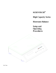
1
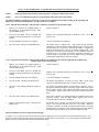
SCIENTECH®
Electronic Balance
Setup and
Operating
Procedures
TABLE OF CONTENTS
UNPACKING AND SETUP.......................................................................................................................................................................................... 3
GOOD MEASUREMENT PRACTICES ....................................................................................................................................................................... 5
EQUIPMENT ...................................................................................................................................................................................................... 5
ENVIRONMENT................................................................................................................................................................................................. 5
OPERATOR........................................................................................................................................................................................................ 5
THE ON/OFF SWITCH ............................................................................................................................................................................................... 6
THE ZERO SWITCH................................................................................................................................................................................................... 6
UNIT OF WEIGHT SELECTION ................................................................................................................................................................................. 6
THE SEND SWITCH................................................................................................................................................................................................... 6
RANGE SELECTION (DUAL RANGE BALANCES ONLY).......................................................................................................................................... 7
THE FUNCTION SWITCH .......................................................................................................................................................................................... 7
(CAL 1) AUTOCALIBRATION - USING AN EXTERNAL CALIBRATION WEIGHT...................................................................................................... 7
(CAL 1) AUTOCALIBRATION - USING 9000-INT MOTORIZED INTERNAL CALIBRATION WEIGHT ....................................................................... 8
(PCS) FRONT PANEL PARTS COUNTING ................................................................................................................................................................ 9
(HI-OK-LO) CHECKWEIGHING / PROCESS CONTROL LIMITS ............................................................................................................................... 9
( T ) LIVE ANIMAL WEIGHING / SEVERE ENVIRONMENT WEIGHING ................................................................................................................ 10
(CAL 100) PERCENT WEIGHING............................................................................................................................................................................. 10
FLOATING TARE™ (DUAL RANGE MODELS ONLY).............................................................................................................................................. 10
CAPACITY TRACKER .............................................................................................................................................................................................. 11
SELECTABLE FILTERS, STABILITY INDICATOR, AND SEND-WHEN-STABLE .................................................................................................... 11
BELOW BALANCE WEIGHING ................................................................................................................................................................................ 11
SPECIFIC GRAVITY DETERMINATION................................................................................................................................................................... 12
DENSITY DETERMINATION .................................................................................................................................................................................... 12
SECURITY BRACKET..................................................................................................................................................................................... 12
OPTIONS.................................................................................................................................................................................................................. 12
OPTIONAL RS-232 PRINTERS....................................................................................................................................................................... 12
RS-232 INTERFACE................................................................................................................................................................................................. 13
RS-232 SPECIFICATIONS .............................................................................................................................................................................. 13
RS-232 FRONT PANEL CONFIGURATION .................................................................................................................................................... 13
USING BI-DIRECTIONAL COMMUNICATIONS .............................................................................................................................................. 15
BI-DIRECTIONAL RS-232 COMMAND SET.................................................................................................................................................... 15
RS-232 BALANCE MESSAGE FORMATS ...................................................................................................................................................... 19
BI-DIRECTIONAL RS-232 ERROR MESSAGES............................................................................................................................................. 20
TROUBLESHOOTING GUIDE .................................................................................................................................................................................. 21
ENVIRONMENTAL REQUIREMENTS ...................................................................................................................................................................... 22
SPECIFICATIONS SM SERIES SEMI-MICRO BALANCES...................................................................................................................................... 22
SPECIFICATIONS SA SERIES ANALYTICAL BALANCES ...................................................................................................................................... 23
SPECIFICATIONS SP SERIES PRECISION BALANCES ........................................................................................................................................ 24
SPECIFICATIONS SL SERIES LABORATORY BALANCES .................................................................................................................................... 25
SPECIFICATIONS SG SERIES GENERAL BALANCES .......................................................................................................................................... 26
SE SERIES GEM BALANCES .................................................................................................................................................................................. 26
CE MARK.................................................................................................................................................................................................................. 27
LIMITED WARRANTY............................................................................................................................................................................................... 27
EXTENDED WARRANTY ......................................................................................................................................................................................... 27
RETURNED GOODS PROCEDURE......................................................................................................................................................................... 27
2
Thank you for choosing a Scientech Electronic Balance. Scientech, an ISO9000 registered company, and its employees are pleased
to provide you with a balance designed and manufactured for years of reliable service and proudly made in the U.S.A. The
attractive quality of Scientech balances has been demonstrated by being certified to carry the “CE” mark of conformity.
Please read this manual completely before using your balance. This information will enable you to fully utilize your balance and
should be located nearby to be used as a juice reference guide. The balance is intended to be used only in the manner outlined in this
manual. Misuse of the balance may cause product failure.
UNPACKING AND SETUP
The balance, weighing pans, remote power supply, windscreen (standard on some models) and keyboard (optional) are packed in a
foam support to protect them from shock during shipping and handling. Save and reuse all packing material for future damage-free
shipments.
3
All balances are equipped with a special clamping screw that locks the balance suspension during shipping. This screw must
be loosened before the balance can be operated (see Figure 2).
1.
Locate the black knob, on the front center of the balance, underneath the display area.
2.
Remove the paper tag.
3.
Turn the knob, in the direction shown below, until finger tight.
If the balance is ever shipped or moved long distances, the clamping screw should be retightened by turning the knob in the
opposite direction until finger tight.
Figure 2 Unlocking Clamping Screw
The environment in which your balance is used is very important. Air movement, temperature changes, vibrations, direct sunlight, etc.
influences the performance of high precision balances. Therefore, place your balance on a solid, sturdy surface that is free of air
currents and vibration. The surface should not be magnetic and should be located away from doors, windows, heaters, air conditioners
and fans.
Adjust (turn) the FRONT FEET (see Figure 3) to level the balance by centering the bubble in the LEVEL INDICATOR which is
shown in Figure 1. Turning the foot as shown below raises that side of the balance and an opposite adjustment lowers it. When
properly adjusted the metal center shaft of the assembly will protrude from the center of the plastic foot and will support the balance.
The plastic foot will be raised up against the bottom of the balance and will not be touching the weighing table.
Figure 3 Leveling
Before making any connections, verify that the power (VAC) requirement shown on the remote power supply is compatible with the
AC power outlet to which the balance will be connected. First plug the round DIN connector into the rear panel receptacle.
Then, plug the power supply into a grounded AC outlet. Do not alter or bypass the ground plug in any way. Doing so
adversely affects the performance of the balance.
NOTE:
Your balance must be plugged in for at least one (1) hour, then calibrated, prior to use. Please see the
Autocalibration instructions section for details.
4
GOOD MEASUREMENT PRACTICES
(As quoted from the Mass Standards Handbook by Troemner, 3-015BKT rev 1/03)
There are numerous steps that one can take in order to improve the quality of a mass measurement system. However, they usually
fall within three main categories: the equipment, the environment, and the operator. If even one of these areas in neglected, it can
have a dramatic negative impact on your results. Although these suggestions are not meant to be all encompassing or all-inclusive,
the improvements that can be made following these simple guidelines are extraordinary.
1.
2.
3.
4.
5.
6.
1.
2.
3.
4.
5.
1.
2.
3.
4.
EQUIPMENT
Select weights that have a tolerance that is one third or better than the accuracy you require for your application. This way
the error of the weight will not dramatically impact the quality of your measurements.
The equipment must be of sufficient readability to calibrate or measure the weight or sample under test.
The balance should be placed on a stable platform free from the effects of vibration. The most common type of setup
involves placing the instrument onto a balance table that is constructed of marble or granite.
Never use a balance or scale as soon as it is turned on (plugged in). The internal electronic components need to stabilize
and “warm up” for at least 24 hours once the equipment has been energized. Troemner recommends that you leave this
instrument plugged in twenty four hours a day, seven days a week.
Never use a balance that has been idle for several hours without first "exercising it" and calibrating it. A balance is
exercised by repeatedly placing and removing weights from the balance pan. We recommend that this be done at least ten
times each with a weight that is 100% of the max capacity of the balance. After exercising, the balance should be
calibrated. If these two techniques are consistently employed, a noticeable improvement will result in both linearity and
stability of the measurement.
When weights are not in use, store them in the case in which they were supplied. If the weights were not supplied with a
case, either purchase a case or use a clean container to protect the surfaces. This will keep airborne particles from getting
on your weights between uses. Weights should be in thermal equilibrium with the balance so store weights near your
balance. Another option is to leave calibration masses commonly used inside the weighing chamber when not in use.
This assures your weights are in thermal equilibrium with the balance producing a better measurement.
ENVIRONMENT
The more stable your environment, the better your measurement results. Changes in temperature, pressure, and humidity
affect balance performance and weight stability. Ideal room conditions are 20º C with a relative humidity between 45%
and 60%. Fluctuations in temperature should not exceed 1º C per hour. Humidity fluctuations should not exceed 10%
per hour.
Balances should not be placed in close proximity to anything that shakes, vibrates, or stirs violently. Avoid placing your
equipment near centrifuges, vortexers, or shakers.
Do not place your balance and/or scale near anything that generates heat. Heat will cause the balance chamber to warm
and due to the effects of the thermal expansion introduce large errors into your measurement. Do not place the balance
near a window. Sunlight can penetrate the window, warm the balance chamber at different rates during the day, and affect
the quality of your work.
Avoid placing the balance near sources of drafts, extreme air currents, or near air-conditioning vents. These positions can
cause your readings to be unstable and can dramatically cool the balance chamber when the air-conditioning system begins
to run.
The measurement environment should be clean and free of excessive contaminants. Contaminants such as dirt and grease
can adversely affect the weight of an object.
OPERATOR
Never touch a weight with your bare hands. Oils and contaminants from your hand will be transferred to the weight and
introduce a significant error. It is recommended that all weights be manipulated with gloved hands or forceps. The two
types of gloves that are commonly used and accepted are either latex (powderless) or cotton. Avoid any metal to metal
contact when handling or storing weights. This will cause scratches that may introduce error. All weight forceps and
weight lifters should be either nonmetallic (plastic or wood) or if metal, covered with a soft protective coating or material
to avoid scratches.
Place the weight or sample near the center of the balance pan. A small offset from center can have a pronounced effect
and introduce undue variation.
Take special care not to breathe onto the weight or into the balance chamber. Back away from the instrument. This will
prevent any thermal transfer of heat from your breath or body to the balance, the weight, or the sample.
Time your measurements. Consistent sample times will provide more consistent measurement.
5
Figure 4
Front Panel
THE ON/OFF SWITCH
Press the ON/OFF switch (see Figure 4) and observe the turn on sequence shown in Figure 5. During this sequence the balance is
doing an automatic systems checkout to insure it is functioning properly.
If your balance was purchased with the optional 9000-INT motorized internal calibration weight, all objects on the stainless steel pan
must be removed before turning on the balance using the front panel ON/OFF switch. Press the ON/OFF switch and observe the turn
on sequence shown in Figure 5. With the 9000-INT installed, the balance will then load the internal weight on and off the weighing
sensor in order for the internal weight to be positioned correctly. Please wait until all weight readings have stopped changing, the “OK”
annunciator appears, and the motor is silent before zeroing the balance and starting weighing operations.
Figure 5
Turn On Sequence
THE ZERO SWITCH
Pressing the ZERO switch (see Figure 4) at any time returns the display to zeros. When a weighing that has been zeroed out is
removed from the pan, a negative reading is displayed. To return to zeros, press the ZERO switch. An optional remote foot zero
switch is available as an accessory.
UNIT OF WEIGHT SELECTION
Note: The SM Series has two units of measure. They are grams (g) and milligrams (A).
Pressing the MODE switch (see Figure 4) starts the unit of weight cycle as follows: grams(g), carats(ct), pennyweights(dwt), troy
ounces(ozt), and ounces(oz). When the desired unit of weight appears, press the MODE switch a second time to select that unit of
weight.
An optional, factory installed, user specified, custom unit of measure is available. If you have this special unit of measure feature in
your balance, (A) appears in the unit of weight cycle after ounces. Press the MODE switch to select this function.
THE SEND SWITCH
NOTE: Scientech balances are DTE (computer) devices. If communicating to another DTE device (ie computer), a
Scientech RS232 cable (PN10697) or normal null-modem cable is required. If you are communicating to a DCE device
(printer), a modem cable is required. Scientech offers an optional modem cable (PN10170) for your convenience.
Pressing the SEND switch (see Figure 4) sends the information on the display to an external device via the RS-232 interface.
You may send the time and date along with the weight reading when you press the SEND switch or you may send weight readings
automatically at user specified time periods (see the Bi-directional RS-232 Command Set, Type 4 Commands section for details).
Weight readings may also be sent to a computer or printer continuously every 200 milliseconds (see the RS-232 Front Panel
Configuration section for details). Weight readings may be sent automatically when the balance reaches stability (see Selectable Filters
section). An optional, factory installed, remote foot send switch is also available.
6
RANGE SELECTION (dual range balances only)
Pressing the RANGE switch selects low (LO), high (HI) and autorange (HI LO). As a range is selected, it briefly appears at the left of
the display. Autorange automatically switches from low range to high range when a weighing exceeds the capacity of the low range.
The Floating Tare feature is only available in the LO range (see Floating Tare section for details).
THE FUNCTION SWITCH
NOTE:
On dual range models, pressing the MODE and RANGE switches simultaneously will duplicate the functions of
the FUNCTION switch found on single range models.
Pressing the FUNCTION switch (see Figure 4) cycles the display through six functions as follows:
*PCS - front panel parts counting
HI OK LO - checkweighing
CAL 1 - autocalibration
CAL 2 - factory set - do not use
T - Live animal weighing
CAL 100 - % weighing
To access the desired function, press the MODE switch when it appears on the display.
* Parts counting through the front panel is not functional with an optional PDA or bi-directional RS-232 enabled.
(CAL 1) AUTOCALIBRATION - Using an External Calibration Weight
NOTE:
If your balance has a motorized internal calibration weight (9000-INT), please use the procedure for
Autocalibration Using 9000-INT Motorized Internal Calibration Weight.
NOTE:
Dual range models must be placed in HI range before starting the calibration procedure.
NOTE:
For correct calibration weight refer to specification charts in the back of the manual.
The balance should be warmed up for at least one (1) hour prior to calibration and leveled according to the Unpacking and
Setup section. Perform autocalibration every time you move your balance. Calibrate the balance using a recently certified
external calibration weight. Metrology handbooks state that the calibration weight utilized to calibrate a balance should have a
tolerance no larger than the readability of the balance divided by 3. Therefore, SM models need a ±0.0033mg tolerance weight or
better, SA models need a ±0.033mg tolerance weight or better, SP models need a ±0.33mg tolerance weight or better, SL models
need a ±3.3mg tolerance weight or better, and SG models need a ±33mg tolerance weight or better. In addition, these same
handbooks recommend that all balances be calibrated using an external certified calibration weight even if the balance has an
internal calibration weight.
1.
Remove any containers or weighing samples so
that nothing is on the stainless steel pan. Then
press the ZERO switch.
Zeros are displayed.
2.
Press the FUNCTION switch (or MODE and
RANGE switches simultaneously for dual range
models).
Display cycles repeatedly through PCS, HI-OK-LO, CAL1, CAL2,
and CAL 100.
3.
Press the MODE switch when CAL1 appears.
CAL1 and a flashing 0 are displayed.
4.
Wait 10 seconds. Then press the ZERO switch.
The display stops flashing. In about 10 seconds, either a single weight
value or two alternating weight values will flash on the display.
5.
Place one of the flashing calibration weights on
the pan.
The display stops flashing and the selected weight is displayed. If Err 1
appears, the calibration weight is an incorrect weight. Remove the weight
and use a proper weight. If Err 2 appears, the balance is not warm enough
for calibration. Wait one hour before starting the calibration procedure
again.
6.
Wait 10 seconds. Then press the ZERO switch.
The weight continues to be displayed for about 10 seconds while the
calibration takes place. Then the display blanks, displays “OK”, and
displays the calibration weight value. The balance is now calibrated.
7.
Remove the calibration weight.
The display returns to zeros and the normal weighing mode.
7
T,
(CAL 1) AUTOCALIBRATION - Using 9000-INT Motorized Internal Calibration Weight
NOTE:
Dual range models must be placed in HI range before starting the calibration procedure.
NOTE:
For correct calibration weight refer to specification charts in the back of the manual.
The balance should be warmed up for at least one (1) hour prior to calibration and leveled according to the Unpacking and
Setup section. Perform autocalibration every time you move your balance.
CAL 1 Using the Internal Weight (This procedure calibrates your balance to the internal weight)
1.
Remove any containers or weighing samples so
that nothing is on the stainless steel pan. Then
press the ZERO switch.
0.0000 is displayed.
2.
Press the FUNCTION switch (or MODE and
RANGE switches simultaneously for dual range
models).
Display cycles repeatedly through PCS, HI-OK-LO, CAL1, CAL2,
and CAL 100.
3.
Press the MODE switch when CAL1 appears.
CAL1 and a flashing 0 are displayed.
4.
Wait 10 seconds. Then press the MODE switch.
The display shows a flashing CAL. This means that the automatic
calibration procedure using the internal weight has begun. The procedure
will take about 30 to 90 seconds. When the procedure is complete, the
display will blank and then return to its normal weighing mode. This
means that your balance is now calibrated. If the calibration cannot be
completed due to air currents, an unstable environment (vibration), an
incorrect weight, or any other reason; a brief “ERR” message will appear
on the display and the balance will return to Step 3.
T,
CAL 1 Using an External Weight (This procedure calibrates your balance to the external weight and then calibrates the
internal weight to the external weight)
1.
Remove any containers or weighing samples so
that nothing is on the stainless steel pan. Then
press the ZERO switch.
0.0000 is displayed.
2.
Press the FUNCTION switch (or MODE and
RANGE switches simultaneously for dual range
models).
Display cycles repeatedly through PCS, HI-OK-LO, CAL1, CAL2,
and CAL 100.
3.
Press the MODE switch when CAL1 appears.
CAL1 and a flashing 0 are displayed.
4.
Wait 10 seconds. Then press the ZERO switch.
The display stops flashing. In about 10 seconds, either a single weight
value or two alternating weight values will flash on the display.
5.
Place one of the flashing calibration weights on
the pan.
The display stops flashing and the selected weight is displayed. If Err 1
appears, the calibration weight is an incorrect weight. Remove the weight
and use a proper weight. If Err 2 appears, the balance is not warm enough
for calibration. Wait one hour before starting the calibration procedure
again.
6.
Wait 10 seconds. Then press the ZERO switch.
The weight continues to be displayed while the calibration takes place
(about 10 seconds). Then the display blanks, displays “OK” for one
second, then shows CAL1 and a flashing 0.
7.
Remove the calibration weight. Then press the
ZERO switch.
The display shows a flashing CAL and the internal weight recalibration
begins. The procedure will take about 30 to 90 seconds. When the
procedure is complete, the display will blank and then return to its normal
weighing mode. The balance is now calibrated to the external weight and
the internal weight is calibrated to the external calibration weight.
RS-232 Command for CAL 1 Using the Internal Weight
To initiate a CAL 1 using the motor driven internal calibration weight via a RS-232 command, issue the command ACAL[CR]. The
automatic internal weight calibration will begin immediately without further user interaction. For a more complete discussion about
RS-232, please see the Bi-directional RS-232 Command Set section.
8
T,
(PCS) FRONT PANEL PARTS COUNTING
NOTE:
Access to the pieces function, via the front panel, is disallowed if a PDA is functional or bi-directional RS-232 is
enabled. RS-232 is enabled by selecting local control (LC) OFF (see RS-232 Front Panel Configuration section
for details). Local control ON means the front panel controls the balance.
1.
Press the FUNCTION switch (or MODE and
RANGE switches simultaneously for dual range
models).
Display cycles repeatedly through PCS, HI-OK-LO, CAL1, CAL2,
and CAL 100.
2.
Press the MODE switch when PCS appears on
the display.
PCS and 0 flash. This is a prompt to zero the balance with the container
that will hold the pieces on the weighing pan.
3.
Place the empty container on the pan, wait 10
seconds, and then press the ZERO switch.
PCS and 10 flash. This is a prompt to place 10 pieces in the container.
4.
Place 10 pieces in the container, wait 10 seconds,
and then press the ZERO switch.
PCS continues to flash and OK appears on the display while a stable
weight is obtained. Then 10.000, or something very near it, appears on
the display. The number of decimal places depends on the weight. PCS
continues to flash. This prompts you that you may now increase the
sample size in order to obtain a more statistical significant sample which
yields a more accurate parts counting conversion factor. The decimal
places aid you in rounding the piece count correctly as the sample size
increases.
5.
If you want a larger sample size to be used in
computing the parts counting conversion factor,
add pieces (the balance will count them) until the
decimal part is near 0.7 or 0.3. Then press the
ZERO switch.
The balance will round to the nearest whole number but still show the
decimal places. This step may be repeated as many times as you desire.
6.
When you are satisfied the sample size is large
enough, press the ZERO switch once again.
The balance rounds to the nearest whole number, the decimal places
disappear, and PCS lights steadily.
7.
When you wish to count something else, press the
MODE switch.
You are now back at Step 2 with a flashing PCS and 0.
8.
If you want to exit the counting mode, press the
MODE switch again.
You are now in the weighing mode you used just before selecting the
parts counting mode.
T,
(HI-OK-LO) CHECKWEIGHING / PROCESS CONTROL LIMITS
1.
Press the FUNCTION switch (or MODE and
RANGE switches simultaneously for dual range
models).
Display cycles repeatedly through PCS, HI-OK-LO, CAL1, CAL2,
and CAL 100.
2.
Press the MODE switch when HI-OK-LO
appears on the display.
HI, OK, and LO flash.
3.
Press the ZERO switch.
HI flashes and zeros are displayed.
4.
Place weight on the pan which represents the
upper control limit of the acceptable weight
range.
HI flashes and the upper weight is displayed.
5.
Press the ZERO switch.
LO flashes and the upper weight is displayed.
6.
Remove the upper limit weight and place weight
on the pan which represents the lower control
limit.
LO flashes and the lower weight is displayed.
7.
Press the ZERO switch.
HI-OK-LO briefly appears and then OK and the lower weight are
displayed.
8.
Remove the lower limit weight.
LO appears and zeros are displayed.
The balance is now ready to checkweigh samples. The balance displays OK along with the weight of the sample if the sample is within
the acceptable weight range. If the sample is too heavy, HI and the weight are displayed. If the sample is too light, LO and the weight
are displayed. The weight limits are stored until the balance is turned off.
To exit check weighing, press the MODE switch. The balance then returns to normal operation.
9
T,
( T ) LIVE ANIMAL WEIGHING / SEVERE ENVIRONMENT WEIGHING
1.
Press the FUNCTION switch (or MODE and
RANGE switches simultaneously for dual range
models).
2.
Press the MODE switch when
display.
3.
Place a container/cage on the pan.
T appears in the display as well as a slowly increasing weight of the
container/cage.
4.
Press the ZERO switch to zero out the
container/cage weight.
T appears in the display as well as zeros.
5.
Remove the container/cage and place the
sample/animal in the container/cage.
A slowly decreasing negative weight is displayed.
6.
Replace the container/cage with the enclosed
sample/animal on the weighing pan.
After the sample/caged animal is placed on the pan, the weight reading
will slowly stop decreasing and then slowly start increasing as the weight
reading is averaged over time. When the weight stops drifting upward,
you have reached the final time averaged weight reading.
7.
If you want to reach the final time averaged
weight reading more quickly, press the
FUNCTION switch (or the RANGE switch on
dual range models).
This resets the time
averaging mode.
The final time averaged weight reading is reached more quickly.
8.
If you want to exit the time averaging weighing
mode, press the MODE switch.
You are now in the weighing mode you used just before selecting the time
averaging mode.
T appears in the
Display cycles repeatedly through PCS, HI-OK-LO, CAL1, CAL2,
and CAL 100.
T,
T appears in the display and you are now in the time averaging weighing
mode.
(CAL 100) PERCENT WEIGHING
1.
Place an empty container on the weighing pan
and press the ZERO switch.
Zeros are displayed.
2.
Place the sample which represents 100% in the
weighing container.
Display indicates the weight of the sample in the unit of measure you have
selected.
3.
Press the FUNCTION switch (or MODE and
RANGE switches simultaneously for dual range
models).
Display cycles repeatedly through PCS, HI-OK-LO, CAL1, CAL2,
and CAL 100.
4.
Press the MODE switch when CAL 100 appears
on the display.
Display will indicate CAL and 100.00. This means that the weight on the
pan now represents 100.00%. You are now in the percent weighing mode
with all weight readings displayed as a percent of the weight of the sample
used in Step 2.
5.
If you want to exit the percent weighing mode,
press the MODE switch.
You are now in the weighing mode you used just before selecting percent
weighing.
FLOATING TARE™ (dual range models only)
Floating tare is only active when the balance is in LO range. Floating tare yields low range resolution throughout the entire high range
capacity of the balance. A typical example using floating tare would be where you combine different components by weight to produce
compounds. The procedure is as follows.
1.
Select LO range by pressing the RANGE switch until LO briefly appears in the display.
2.
Place container on weighing pan. If the container weight exceeds LO range capacity, OL is displayed. If the container weight
does not exceed the LO range capacity, the container weight is displayed.
3.
Press ZERO switch. Display returns to zeros and LO range.
4.
Add first component until target weight is reached. Then press ZERO.
5.
Add second component until target weight is reached. Then press ZERO.
6.
Continue until all components have been added.
Floating tare allows you to enter the LO range from anywhere within the full capacity range of the balance. This feature is particularly
useful when adding small amounts to large tare loads and compounding where weights are accumulated. Floating tare is only active
when the balance is in LO range. Pressing the ZERO switch returns the display to zeros in LO range. While you are using the floating
tare feature, it is easy to lose track on how much capacity has been used. The Capacity Tracking feature is a helpful tool. Please see
the following discussion.
10
T,
CAPACITY TRACKER
The capacity tracker provides a graphic display of the used and unused portions of the weighing range. Each segment represents 5% of
the balance's capacity and is illuminated as that portion of the capacity is used. The larger segments, representing 1/4, 1/2, 3/4, and full
load, flash as they are approached and then become solid again as they are exceeded.
SELECTABLE FILTERS, STABILITY INDICATOR, AND SEND-WHEN-STABLE
All balances are equipped with three user-selectable vibration filters which reduce nervous readings in varying weighing conditions.
The balance was delivered to you set in the high filtering mode (Fil HI). This is the most aggressive filtering mode. Normal filtering
(Fil nor) and low filtering (Fil Lo) can be selected for quieter conditions and faster response.
The stability indicator, OK, is illuminated when the balance has determined that all readings are within the stability parameters as
selected by the user. The balance was delivered to you with stability set at ±2 display counts, which is represented by a 0 in step 5
below. You may select stability from ±1 to ±10 display counts manually in step 5 below. If the weight readings are outside the
acceptable limits, the stability indicator will not light. The stability indicator can be disabled, if desired. Also, the send-when-stable
command sends the weight reading over the RS-232 interface whenever the OK light illuminates. The balance was delivered to you
with the send-when-stable command OFF. When it is ON, the auto and continuous send commands (see RS-232 Front Panel
Configuration for details) are not functional.
To enter the selection mode proceed as follows: To exit the selection mode and return to normal operation, turn the balance off and
then back on again at any time.
1.
Turn the balance off using the ON/OFF switch.
Display blanks.
2.
Hold the MODE switch down while turning the
balance on using the ON/OFF switch.
OK and the current filter, Fil nor (filtering normal), Fil Lo (filtering low),
or Fil HI (filtering high) are displayed.
3.
Press the SEND switch until the desired vibration
filter is displayed. Then press the ZERO switch
to save the setting.
OK SAVEd is displayed followed by the current stability indicator
setting, Si on (stability indicator will turn on when reading is stable) or Si
oFF (stability indicator will always be turned off).
4.
Press the SEND switch until the desired stability
indicator Si setting is displayed. Then press the
ZERO switch to save the setting.
OK SAVEd is displayed followed by the current stability sensitivity
setting SEnS (the default is ±2 display counts).
5.
Press the SEND switch until the desired stability
sensitivity display counts setting is displayed.
Then press the ZERO switch to save the setting.
OK SAVEd is displayed followed by the current send-when-stable SS
setting (oFF is the default).
6.
Press the SEND switch until the desired send
when stable SS command is displayed. Then
press the ZERO switch to save the setting.
OK SAVEd is displayed. Then the balance cycles back to Step 2 and
shows the current filter setting.
7.
Press the ON/OFF switch.
The display blanks.
8.
Press the ON/OFF switch.
The balance returns to normal operation with the new vibration filter and
stability indicator settings in place.
Note:
BELOW BALANCE WEIGHING (Not available on SM balances)
Please use care when installing Below Balance Weighing. The suspension can be damaged if over tightened.
The overload protection built into the pan assembly is not available at the below balance hanging device.
Therefore, care must be taken to avoid side shocks or pulling too hard on the hanging device.
For applications requiring suspension of weighings below the balance, a 6-32 threaded screw is provided. To access the set screw,
proceed as shown. Then mount the balance on a solid pedestal or surface with a hole under the balance to allow access to the hanger.
While using the below balance weighing feature all other functions of the balance operate normally. The balance is capable of
weighing both above and below simultaneously provided the capacity of the unit is not exceeded.
Figure 6
Below Balance Weighing
11
SPECIFIC GRAVITY DETERMINATION
The below balance weighing apparatus shown previously is ideal for determining specific gravity. Specific gravity is the ratio of
the mass of a body to the mass of an equal volume of water. Every mineral has its own specific gravity (SG). A list may be found
in any Handbook of Chemistry and Physics. Specific gravity will classify or authenticate a substance. For instance, a diamond’s
SG is 3.50-3.53 while quartz’s is 2.65.
To determine specific gravity using our balance:
1. Install a below balance weighing hangar as shown in the previous section.
2. Install a below balance weighing apparatus, such as a wire hook, including a pan suspended in a bowl of water. Insure that the
pan and the hanger do not touch any part of the bowl and all are totally submerged. Then tare the balance.
3. Then place the sample to be tested on the balance pan and record the weight reading shown on the display. You may use any
unit of measure you desire.
4. Then place the same sample to be tested on the pan suspended in the bowl of water. Make sure that the sample is completely
submerged in the water and record the weight reading shown on the display.
5. Subtract the reading in Step 4 from the reading in Step 3.
6. Divide the reading in Step 3 by the number calculated in Step 5. The result is the SG of your sample.
EXAMPLE: Reading in Step 3 = 6.50
Reading in Step 4 = 4.25
Subtraction
= 2.25
Division (Step 6)
= 6.50/2.25= 2.89 specific gravity
DENSITY DETERMINATION
Scientech does not offer a density determination kit nor do you need one to determine density. Density is mass (grams) per unit
volume (cubic centimeters).
In order to determine density of a solid, place a graduated flask with a known volume of water on the pan of the balance, tare the
balance, and then place the solid in the flask of water. Divide the displayed weight in grams by the increased volume of water. The
result is the mass per unit volume of the solid in g/cc.
To determine the density of a liquid, place an empty graduated flask on the balance weighing pan, tare the balance, then pour the
liquid into the graduated flask. Divide the displayed weight in grams by the volume of the liquid. The result is the mass per unit
volume of the liquid in g/cc.
SECURITY BRACKET
A security bracket is provided on the rear panel. If needed, the bracket slides out of the rear of the balance providing a convenient
method of securing the balance.
OPTIONS
The Motorized Internal Calibration Weight (9000-INT), Remote Weighing (7000-04) and Custom Unit of Measure (9000-90) options
must be installed at the factory or by personnel authorized by Scientech. Other options, such as a Scientech PDA and printers, may be
purchased at any time. Please contact Scientech at (303)444-1361 or (800) 525-0522 or email us at [email protected] for
information.
OPTIONAL RS-232 PRINTERS
(Printers must be serial)
There are a few different models to choose from. Please contact Scientech or one of our representatives for more information. A
comprehensive manual is included with each printer when purchased. All printers are set for a 9600 baud rate. To change this setting
please see the printer manual and the RS-232 Front Panel Configuration section. The balance display contents can be sent to the printer
at any time by pressing the balance front panel SEND switch . Balances only communicate with serial printers.
Many other accessories are available. Please contact Scientech at 303-444-1361 or 800-525-0522 or email us at [email protected] for more information.
12
RS-232 INTERFACE
NOTE: Scientech balances are DTE (computer) devices. If communicating to another DTE device (ie computer), a
special Scientech RS232 cable (PN10697) is required. If you are communicating to a DCE device (printer), a modem cable
is required. Scientech offers an optional modem cable (PN10170) for your convenience.
Your balance is equipped with a bi-directional RS-232 compatible interface. The interface is uni-directional (balance send only) when
the local control is set to ON. To enable the bi-directional interface, set the local control to OFF (see the following RS-232 Front Panel
Configuration section). The RS-232 connector is a 9 pin D subminiature connector located on the balance rear panel. The pinout and
pin descriptions are shown in Figure 7.
Figure 7 Connector Pinout
NOTE: The Ext reset function is disabled in all balances when they are delivered. To enable the feature pin 1 of the internal
dipswitch must be closed. Please contact customer service with any questions.
The balance will not output any information under any circumstances unless pin 8 (CTS) is held in an ON state (+3 to +15 VDC).
Interfaces not utilizing the CTS handshake may tie pin 8 to pin 7 or pin 8 to pin 4 to defeat it.
This interface does not strictly adhere to the official RS-232 standard. However, it emulates what has become commonplace in the
microcomputer industry.
RS-232 SPECIFICATIONS
Type
Method
Format
Note:
EIA-RS-232C, DTE
Half-duplex, Asynchronous Transmission, Bi-directional
300, 600, 1200, 2400, 4800, 9600 and 19,200 baud rate selectable (default is 9600)
Code: ASCII
For parity Even or Odd: Data bit 7, Stop bit 1.
For parity none:
Data bit 7, Stop bit 2.
Parity none, Data bit 8, Stop bit 1 does function, but is not technically correct.
RS-232 FRONT PANEL CONFIGURATION
Before using the RS-232 feature of your balance, it is necessary to configure the interface properly for your application. The RS-232
Configuration Mode allows you to set baud rate, front panel control, software protocol, parity, auto send, continuous send, and display
blanking. The balance is configured with defaults at the factory. The default modes are shown in parenthesis below.
It is not necessary to follow the entire configuration procedure if only one parameter is to be changed. Follow Steps 1 and 2, then use
the MODE switch to select the parameter to be changed, skipping the others. Select the desired setting using the SEND switch, save
the setting using the ZERO switch, then turn the balance off and then on again with the ON/OFF switch.
To enter the RS-232 configuration mode via the front panel, proceed as follows:
1.
Turn the balance off using the ON/OFF switch.
Display blanks.
2.
Hold the SEND switch down while turning the
balance on using the ON/OFF switch.
OK and the current baud rate, br300, br600, br1200, br2400, br4800,
br9600, or br19,200 is displayed.
3.
BAUD RATE SELECTION (9600 is default).
Press the SEND switch until the desired
baud rate is displayed. Then press the
ZERO switch.
OK SAVEd is displayed followed by OK and the chosen baud rate.
13
4.
LOCAL CONTROL SELECTION (LC on is
default). “LC on” means that the front panel
switches control the balance. To enable a
computer to control the balance, “LC oFF” must
be selected.
Press the MODE switch.
Press the SEND switch to choose between
on or off. Then press the ZERO switch.
5.
PROTOCOL or HANDSHAKE SELECTION
(Pr on is default).
Press the MODE switch.
Press the SEND switch to choose between
on or off. Then press the ZERO switch.
6.
PARITY SELECTION (PA nonE is default).
Press the MODE switch.
Press the SEND switch to choose between
EVEn, odd, or nonE. Then press the ZERO
switch.
7.
AUTO SEND SELECTION (AS oFF is default).
“AS on” means the balance will automatically
send the display contents over the RS-232
interface at the selected time interval placed into
register 89. This time interval may be inputted
via the optional PDA or through Type 4 RS-232
commands.
Refer to these sections for
instructions. A time and date stamp may also be
sent at the same time (see Type 4 RS-232
Commands section). The auto send selection is
not functional if the send-when-stable command
is on (see Selectable Filter section).
Press the MODE switch.
Press the SEND switch to choose between
on or off. The press the ZERO switch.
8.
CONTINUOUS SEND SELECTION (CS oFF is
default). “CS on” means the balance will
automatically send the weight reading over the
RS-232 interface at the baud rate selected.
Display readings are updated every 200
milliseconds. The continuous send selection is
not functional if the send-when-stable command
is on (see Selectable Filter section).
Press the MODE switch.
Press the SEND switch to choose between
on or off. Then press the ZERO switch.
9.
DISPLAY BLANKING SELECTION (bL on is
default). “bL on” means that every time data is
sent over the RS-232 interface, the display will
blink.
Press the MODE switch.
Press the SEND switch to choose between
on or off. Then press the ZERO switch.
OK and the current front panel control setting , LC on or LC oFF is
displayed.
OK SAVEd is displayed followed by OK and the chosen setting.
OK and the current software protocol setting, Pr oFF or Pr on is
displayed.
OK SAVEd is displayed followed by OK and the chosen setting.
OK and the current parity setting, PA EVEn, PA odd, or PA nonE is
displayed.
OK SAVEd is displayed followed by OK and the chosen setting.
OK and the current auto send setting, AS oFF or AS on is displayed.
OK SAVEd is displayed followed by OK and the chosen setting.
OK and the current continuous send setting, CS oFF or CS on is
displayed.
OK SAVEd is displayed followed by OK and the chosen setting.
OK and the current display blanking setting, bL on or bL oFF is
displayed.
OK SAVEd is displayed followed by OK and the chosen setting.
10.
Press the ON/OFF switch.
The display blanks
11.
Press the ON/OFF switch.
The balance returns to normal operation with the new RS-232
configuration.
14
USING BI-DIRECTIONAL COMMUNICATIONS
Scientech electronic balances, interfaced to a computer via the RS-232 port, can be controlled by a computer program in the same way
an operator would control the balance using a PDA. Any programming language with access to the RS-232 interface can be used to
program this control. The balance expects ASCII character instruction strings and responds with ASCII character data strings. All
characters with an ASCII value less than the space character (decimal 32 of hex 20), are ignored by the balances.
If local control has been enabled (LC on) via RS-232 front panel configuration, RS-232 communication is limited to balance sending
only as all incoming RS-232 command strings are ignored by the balance. To enable bi-directional RS-232 communication, set the
local control to off (see RS-232 Front Panel Configuration section).
BI-DIRECTIONAL RS-232 COMMAND SET
The following commands can be sent to the balance in any combination of upper and lower case characters. No action is taken by the
balance until it receives a carriage return indicating the end of the command string. Each command's syntax is described using this
notation; keywords are in upper case; items in [ ] are required; when one item must be chosen from a list, each choice is enclosed in (
); CR means the carriage return or enter character; LF means the line feed character; and _ indicates a single space character. A
command string or entry is considered to be a keyword (and/or a numeric string) followed by a carriage return. The commands are
listed by type. Type 1 commands are balance control functions. Type 2 are balance input functions. Type 3 are balance output
functions. Finally, Type 4 are clock/calendar functions. Where a balance response is given, no attempt has been made to show the
actual message formats. You should refer to the section on balance message formats for detailed information. Numbers stored in the
registers are classified by the balance software as being additive, multiplicative, or unflagged. Additive numbers are used by the
balance software in addition and subtraction operations. Multiplicative numbers are used in multiplication and division operations.
Unflagged numbers aren't used in any arithmetic functions. If you try to use an additive number in a function which requires a
multiplicative number the balance responds with the register contents (if applicable) and a ? and the instruction is ignored.
TYPE 1 COMMANDS (balance control functions)
COMMAND
RESPONSE
PURPOSE
CLEAR [CR]
None
Clears the previous command and resets
the balance to normal operating mode.
The Tare register is cleared to zero and
the balance is zeroed.
HI_RANGE[CR] or LO_RANGE[CR] or
AUTO[CR]
None
Set the balance range.
GRAMS[CR] or CARATS[CR] or
DWT[CR] or OZT[CR] or OZ[CR] or
A[CR] or LIMITS[CR] or CAL1[CR] or
CAL2[CR]
None
Places the balance in the indicated mode
or units. To abort any of the CAL
sequences or the LIMITS modes use
CLEAR[CR].
ZERO[CR]
None
The balance takes whatever action it
would in response to a push of the front
panel zero switch. Normally tares the
balance.
TARE[CR]
None
If the balance is in the weighing mode,
this command tares the balance, otherwise
it is ignored.
[decimal number]_HI[CR]
None
Sets the checkweighing high limit register
(register 88) to the decimal number
entered in the current units. Register 88 is
undefined at every ON/OFF cycle.
[decimal number]_LO[CR]
None
Sets the checkweighing low limit register
(register 87) to the decimal number
entered in the current units. Register 87 is
undefined at every ON/OFF cycle.
15
[decimal number]_CONVERT[CR]
None
Loads the number entered, as a "last front
panel units" relative multiplier, into the
CONVERT register and enters the
CONVERT mode. CLEAR exits the
convert mode and undefines the convert
register.
[decimal number]_CAL[CR]
None
Loads a computed number based on the
entered number, as a "last front panel
units" relative multiplier, into the CAL
register and enters the CAL mode. The
display must be non-zero when this
command is issued. If the display is zero,
a 3 second "Err" message is displayed and
the balance returns to its normal weighing
mode. The current weight reads as the
number entered with the appropriate sign.
CLEAR exits the CAL mode and
undefines the CAL register.
[integer]_PIECES[CR]
None
Loads a computed number based on the
entered number, as a "last front panel
units" relative multiplier, into the PIECES
register and enters the PIECES mode.
The display must be non-zero when this
command is issued. If the display is zero,
a 3 second "Err" message is displayed and
the balance returns to its normal weighing
mode. CLEAR exits the pieces mode and
undefines the pieces register.
[Decimal
number]_ENTER_[integer]
_PIECES[CR]
None
Accepts the decimal number as a weight
in "last front panel units" per integer
pieces. If the balance is not in PCS mode,
it goes into PCS mode using the decimal
number/the integer as the weight. If used
when the balance is already in PCS mode,
the display digits are blanked for about 1
second while the PCS an "last front panel
units" annunciators are lit. The balance
then resumes normal PCS operation using
the decimal number/the integer as the unit
weight.
[register
number]_RCL_[(CONVERT)
(CAL) (PIECES)][CR]
REG XXX :[register contents][MULT.]
Puts the recalled register contents into the
specified mode register and enters that
mode.
TAVG[CR]
None
Clears the TBAR registers and enters the
TBAR mode.
RESET_TAVG[CR]
None
Clears the TBAR registers. If the balance
is in the TBAR mode, the process keeps
running.
XAVG[CR]
None
Accumulates the current weight in the
XBAR registers.
RESET_XAVG[CR]
None
Clears the XBAR registers.
GLP[CR]
Sends GLP header
Puts balance in the GLP mode.
XAVG[CR]
Sends weight while in GLP
Accumulates the current weight in the
XBAR registers.
RCL_XAVG[CR]
Sends statistics and signature line
Terminates GLP mode.
ISO[CR]
Sends ISO header and waits for target
weight entry
Puts balance in ISO mode.
xxx.xx_Targ[CR]
Sends target weight (g)
Enter target weight value in grams.
16
SEND[CR]
Sends weight, difference between weight
and target, and signature line
Terminates ISO mode.
ACAL[CR]
None
Starts the automatic internal calibration
weight calibration routine.
TYPE 2 COMMANDS (balance input functions)
COMMAND
RESPONSE
PURPOSE
[register number]_STORE[CR]
None
Stores the current weight, at the greatest
possible resolution, in the specified
register.
[Decimal
number]_ENTER_[register
number]_STORE[CR]
None
Stores the number entered, in the current
units, as an additive constant in the
register specified.
[decimal
number]_ENTER_CONVERT_[register
number]_STORE[CR]
None
Stores the number entered, as a "last front
panel units" relative multiplier, in the
specified register.
[decimal number]_TARE[CR]
None
Adds the number entered, in current units,
to the TARE register. CLEAR [CR]
zeroes the TARE register.
TYPE 3 COMMANDS (balance output functions)
COMMAND
RESPONSE
PURPOSE
SEND[CR]
See the RS-232 Balance Message Formats
section..
Returns the contents of the display
register.
[register number]_RCL[CR]
REG XXX:[register contents][current
units or 'MULT.'] [CR] [LF]
Sends the contents of the specified register
in the current units if it is additive or with
the designator 'MULT.' if it is
multiplicative. An unflagged number is
sent with no designator. An undefined
register returns a ? with a [CR][LF].
RCL_TARE[CR]
REG 091:[TARE register contents]
[current units][CR][LR]
Return the TARE register's contents.
RCL_[(CONVERT)(CAL)]
REG XXX:[contents of specified
register][MULT.][CR][LF]
Returns indicated register contents, if in
that mode. If not in that mode then a ?
with a [CR][LF] is returned.
RCL_PCS[CR]
REG XXX:[contents of pieces
register][last FP units/pc][CR][LF]
Returns pieces register contents expressed
as last front panel units/pc, if in that mode.
If not in that mode then a ? with a
[CR][LF] is returned.
[register number]_RCL_TARE[CR]
REG XXX:[register contents][current
units][CR][LF]
Adds the specified register contents to the
TARE register.
RCL_XAVG[CR]
[average weight] [current units]
AVX[CR][LF]. [2 second delay].
[number of samples taken] ###[CR][LF].
[2 second delay]. [standard deviation] [
current units] SDEV[CR][LF]. [2 second
delay]. [relative standard deviation]
COV[CR][LF].
Sends the results of a standard deviation
run. The TBAR mode, if in use, is
temporarily suspended while this process
is going on.
17
TYPE 4 COMMANDS (clock/calendar functions)
COMMAND
RESPONSE
PURPOSE
None
Sets the calendar function, if available, to
the specified date. The date must be
specified in the MMDDYY format and no
delimiters.
REG 100: MM.DD.YY DATE[CR][LF]
Returns the date.
None
Sets the clock function, if available, to the
specified time.
The time must be
specified in the HHMMSS format using
military 24 hour time format.
101_RCL[CR]
REG 101: [HH:MM:SS] TIME[CR][LF]
Returns the current time, using military 24
hour time format, once for each request.
[1 to 6 digit integer]
_ENTER_89_STORE[CR]
None
Sets the auto send register to the specified
send time interval. For the auto send
feature to be operational, you must set the
auto send selection to ON (see RS-232
Front Panel Configuration section for
details). The format used is HHMMSS
with no delimiters. For instance, to set the
auto send interval to 5 minutes and 25
seconds, you would send this command
string: 525 ENTER 89 STORE[CR].
Also you must have the auto Send
selection set to ON before the auto Send
will work (see RS-232 Front Panel
Configuration Section).
89_RCL[CR]
REG 089: [HH:MM:SS] INTV[CR][LF]
Returns the auto SEND time interval
currently set.
[(1)(0)]_ENTER_79_STORE[CR]
None
A 1 in register 79 disables the date/time
stamp feature of any SEND. A 0 in
register 79, enables the date/time stamp.
[six
digit
_ENTER_100_STORE[CR]
integer]
100_RCL[CR]
[six
digit
_ENTER_101_STORE[CR]
integer]
18
RS-232 BALANCE MESSAGE FORMATS
The balance will respond to a SEND command by transmitting a message in one of three formats depending on how the SEND
command was issued. The following discussion defines four types of SEND commands and the three message formats.
1.
The first case typically applies to a balance with RS-232 connected to a printer and an external print switch. If the SEND is
initiated by activation of the hardware SEND line on the RS-232 I/O module and the display shows the current weight, then
the response will be a format B. If the display does not show the current weight (i.e., date, time, or a register RCL), the
hardware SEND is ignored.
2.
This case typically applies to a balance with the RS-232 interface connected to a printer. If the SEND is initiated by a time or
auto SEND and the display shows the current weight, then the response will be a format B. The date/time stamp is included
in format C if register 79 has been set to 1 prior to setting register 89 to the desired time interval. To stop auto sending set
register 89 to 0. If the date/time stamp is enabled and the display doesn't show the current weight, the date/time stamp is still
sent. Nothing is sent if the date/time stamp is disabled and the display doesn't show the current weight.
3.
This case typically applies to a balance with the RS-232 interface connected to a computer. There are several RS-232 I/O
commands containing the keyword RCL. These commands, issued by the computer, all cause a single format C or a
sequence of format C send to occur.
4.
This case also typically applies to a balance with the RS-232 interface connected to a computer. A SEND command issued over
the RS-232 I/O channel, by the computer, causes an unconditional format A send.
Format A: Balance in the normal weighing mode
1
2
3
4
5
X
X
X
X
X
6
X
7
X
8
-
9
-
10
-
11 CR
Y......
LF
X = a digit (0-9) or a decimal point or a space or a minus sign.
Y = an upper case alphabetic character (A-Z). The first character of the units or mode annunciator in the display, followed by the rest
of the characters of the annunciator.
If the display shows a minus sign, it is the first character in the balance message. In this case the least significant digit of the displayed
number is in position 8 followed by only two spaces instead of three. The 1st character of the units annunciator is still in the 11th
position.
Here are some examples. The notation used here is that CR means the carriage return or enter character; LF means the line feed
character; and _ indicates a single space character. Note that all space characters are shown explicitly.
Display shows 5.15 g
Message is
_ _ _5.15_ _ _G CR LF
Display shows 211.05 dwt
Message is
_211.05_ _ _DWT CR LF
Display shows -211.05 dwt
Message is
-_211.05_ _DWT CR LR
Display shows .0035 A
Message is
_ _.0035_ _ _A_SPEC. CR LF
Format A: Balance in a special weighing mode
Display shows 1250 PCS
Message is
_ _1250_ _ _ _ _PCS CR LF
Note that, in these special weighing modes, the least significant digit of the numeric field is in the 6th (or 7th position if the number is
negative) and that the leftmost character of the annunciator is in the 12th position.
Display shows -100.00 CAL
Message is
-100.00_ _ _ _CAL CR LF
Display shows sigma Tbar 0.00 g
Message is
_ _ _ 0.00_ _ _G_SIGMA_ _TBAR_ CR LF
19
Format B: Balance in normal weighing mode
1
X
2
X
3
X
4
X
5
X
6
X
7
X
8
_
9
_
10
_
11
Y
12
Y
13
Y
14
_
15
_
16
Y
17
Y ...CR LF
Display shows 5.15 g and balance in high range
Message is _ _ _5.15_ _ _G_ _HIGH CR LF
Format B: Balance in a special weighing mode
Display shows 1250 PCS and balance in low range
Message is _ _1250_ _ _ _ _PCS_ _LOW CR LF
Note that, in these special weighing modes, the least significant digit of the numeric field is in the 6th (or 7th position if the number is
negative) and that the leftmost character of the annunciator is in the 12th position.
Format C:
1
R
2
E
3
G
4
:
5
_
6
X
7
X
8
X
9
_
10
_
11
X
12
X
13
X
14
X
15
X
16
X
17
X
18
_
19
_
20
_
21
Y
22
Y
23
CR LF
Display shows the contents of register 24 as 102.56, an additive constant, with units in grams
Message is
REG:_024_ _ _102.56_ _ _G CR LF
Display shows 12:03:35 as the time
Message is
REG:_101_12:03:35_ _ _TIME CR LF
BI-DIRECTIONAL RS-232 ERROR MESSAGES
There are three single character error messages that the balance issues when certain errors occur during bi-directional communications.
Each error character is followed by CR LF.
1.
! is issued when the input buffer is full. Normally this occurs because a CR is lost or the command string is too long. The
balance has a 37 character input buffer which is sufficiently long for all valid command strings. The ! is issued as soon as the
buffer is full and is repeated after each successive character until a CR is received. In response to the CR, a ? and CR/LF is
sent and the balance input buffer is cleared.
2.
: is issued when a parity, overrun, or framing error is detected by the interface since the last CR. The : is sent after the CR
ending the command string which caused the error has been received.
3.
? is issued when a syntax error occurs or when an illegal character is received or when some other procedural error is detected.
The ? is sent after the CR ending the command string which caused the error has been received.
Power up errors are not detectable over the RS-232 I/O channel. The only way to detect such errors is to attempt to communicate with
the balance and have the ability to recognize that the communication is failing. Displayed error messages are only available by polling
the balance using the SEND command. The balance would respond by transmitting the displayed error (i.e., Err 1, Err 2).
20
TROUBLESHOOTING GUIDE
NOTE: Many problems such as the balance remaining in the turn on sequence, "weird" characters on the display or
"garbage" on the display are caused by connecting the power supply to the balance incorrectly. The proper
procedure is to connect the round DIN connector on the power supply cable to the balance then plug the power supply
into the wall outlet.
PROBLEM
POSSIBLE CAUSE
POSSIBLE SOLUTION
The display is blank
*Balance not turned on
*Power cable not plugged in
*No power from AC outlet
*Press ON/OFF switch
*Plug in power cable
*Turn on circuit breaker
*Change AC outlets
OL appears in display
*Maximum capacity exceeded
*Reduce container weight
*Weigh sample in smaller increments
*Switch to high range (dual range units)
*Shipping clamp is on
*Loosen clamp (see page 4)
UL appears in display
*Pan is not in place
*Balance is out of range
*Shipping clamp is on
*Insure pan is positioned properly
*Press ZERO switch
*Loosen clamp (see page 4)
The display is unstable
*Drafts (air currents are present)
*Vibrations are present
*Install windscreen, relocate balance
*Isolate balance from vibration, relocate
balance
Weight readings are incorrect
*Balance is out of calibration
*Balance is not level
*Display was not zeroed before weight
was placed on pan
*Object being weighed is touching
windscreen or balance case top
*Unit of weight selection is incorrect
*Recalibrate balance
*Level balance
*Press ZERO switch before weighing
*Reposition object
*Select proper weighing mode
Display stays in turn on sequence
*Pan not in place
*Drafts or vibrations present
*New windscreen has been installed
*Shipping clamp is on
*Power supply connected to wall outlet
before balance connector
*Place pan on balance
*Isolate or relocate balance
*Raise pan height
*Loosen clamp (see page 4)
*Unplug power supply from wall then
replug into wall
Err 1 appears in display
*Calibration weight is incorrect
*Use calibration weight that appears in
balance display
Err 2 appears in display
*Balance not warmed up enough for
calibration to be performed
*Plug in and turn on balance for 1 hour
Err 3 through 14 appears in display
*Service is required
*Call Scientech's Service Department at
(800) 525-0522 or (303)444-1361 or
email us at [email protected].
21
ENVIRONMENTAL REQUIREMENTS
This product is intended for indoor use at altitudes up to 2000 meters, Pollution Degree 1 or 2 in accordance with IEC 664 and transient overvoltages according to Installation Categories
(Overvoltage Categories) I, II and III. For mains supply, the minimum and normal category is II.
SPECIFICATIONS SM SERIES SEMI-MICRO BALANCES
Model
Weighing Mode
Capacity
SM 50
SM 99
Single Range
50g
80g
120g
.00001g
.0001g
0-80g
0-99g
Repeatability
(Standard
Deviation)
Linearity
.00002g
.00004g
±.00003g
±.00003g
Housing (WxDxH)
Weight
40g
120g
.00001g
Tare Range
Windscreen
Calibration Weight
SM 128D
Dual Range
(Floating Tare™)
99g
Readability
Stabilization Time
Weighing Speed
Display Update
Interval
Data Interface
Pan Size
Operating
Temperature
Relative Humidity
Power Supply
SM 124D
0-120g
0-120g
.00002g
.0001g
0-120g
0-120g
.00003g
.0001g
±.00003g
±.0002g
±.00003g
±.0002g
~8 Seconds
Adaptive
800ms
RS-232 bidirectional interface is standard. Baud rates are 300, 600, 1200, 2400, 4800, 9600 and 19,200.
Circular 3.5 inch diameter
5°C to 40°C
50g
10g
80 % for temperatures up to 31°C decreasing linearly to 50 % at 40°C
115 Volts/60 Hz ± 10 %
230 Volts/50Hz or 60 Hz ± 10 %
7.5W x 8.25D x 9.5H
100g
100g
100g
50g
40g
50g
7.5" x 11.25" x 3.25"
~ 13.8 lbs
22
SPECIFICATIONS SA SERIES ANALYTICAL BALANCES
Model
Weighing Mode
Capacity
SA 80
SA 120
80g
120g
Readability
SA 210
SA 310
Single Range
210g
SA 410
SA 510
310g
410g
510g
.0001g
Tare Range
0-80g
0-120g
0-210g
0-310g
0-410g
0-510g
Repeatability
(Standard
Deviation)
Linearity
.0001g
.0001g
.0001g
.00015g
.00015g
.0002g
Stabilization Time
Weighing Speed
Display Update
Interval
Data Interface
Pan Size
Operating
Temperature
Relative Humidity
Power Supply
Windscreen
Calibration Weight
Housing (WxDxH)
Weight
±.0002g
SA 210D
SA 525D
Dual Range
(Floating Tare™)
100g
250g
200g
500g
.0001g
.001g
0-200g
0-500g
0-200g
0-500g
.0001g
.00015g
.0005g
.0005g
±.0002g
±.0005g
User Selectable
Adaptive
200ms
RS-232 bidirectional interface is standard. Baud rates are 300, 600, 1200, 2400, 4800, 9600 and 19,200.
Circular 3.5 inch diameter
5°C to 40°C
80g
50g
80 % for temperatures up to 31°C decreasing linearly to 50 % at 40°C
115 Volts/60 Hz ± 10 %
230 Volts/50Hz or 60 Hz ± 10 %
7.5W x 8.25D x 9.5H
100g
200g
300g
400g
500g
200g
50g
100g
200g
200g
100g
7.5" x 11.25" x 3.25"
~ 13.8 lbs
23
500g
200g
SPECIFICATIONS SP SERIES PRECISION BALANCES
Model
Weighing Mode
Capacity
SP150
SP250
150g
250g
Readability
Tare Range
Windscreen
Calibration Weight
Housing (WxDxH)
Weight
SP1000
SP1500
500g
1000g
1500g
0-500g
0-1000g
0-1500g
350g
0.001g
0-150g
Repeatability
(Standard
Deviation)
Linearity
Stabilization Time
Weighing Speed
Display Update
Interval
Data Interface
Pan Size
Operating
Temperature
Relative Humidity
Power Supply
SP350
SP500
Single Range
0-250g
0-350g
0.001g
±0.0015g
SP404D
SP510D
SP2050D
Dual Range
(Floating Tare™)
40g
100g
500g
400g
500g
2000g
0.001g
0.01g
0-400g
0-500g
0-2000g
0-400g
0-500g
0-2000g
0.001g
0.005g
±0.0015g
±0.005g
User Selectable
Adaptive
200 ms
RS-232 bidirectional interface is standard. Baud rates are 300, 600, 1200, 2400, 4800, 9600 and 19,200
Circular 4.5 inch diameter
5°C to 40°C
150g
100g
80 % for temperatures up to 31°C decreasing linearly to 50 % at 40°C
115 Volts/60 Hz ± 10 %
230 Volts/50 Hz or 60 Hz ± 10 %
Circular 6 inch diameter x 3.25 inches high
250g
350g
500g
1000g
1500g
400g
500g
200g
200g
500g
1000g
200g
200g
7.5" x 11.25" x 3.25"
~ 9.5 lbs
24
2000g
1000g
SPECIFICATIONS SL SERIES LABORATORY BALANCES
Model
Weighing Mode
Capacity
SL400
SL600
SL1000
SL2000
Single Range
SL3000
SL5000
SL6000
400g
600g
1000g
2000g
3000g
5000g
6000g
0-3000g
0-5000g
0-6000g
Readability
Tare Range
0.01g
0-400g
0-600g
Repeatability
(Standard
Deviation)
Linearity
Stabilization Time
Weighing Speed
Display Update
Interval
Data Interface
Pan Size
Operating
Temperature
Relative Humidity
Power Supply
Windscreen
Calibration Weight
Housing (WxDxH)
Weight
0-1000g
0-2000g
0.01g
±0.015g
SL3100D
SL5200D
Dual Range
(Floating Tare™)
1000g
2000g
3000g
5000g
0.01g
0.1g
0-3000g
0-5000g
0-3000g
0-5000g
0.01g
0.05g
±0.015g
±0.05g
User Selectable
Adaptive
300 ms
RS-232 bidirectional interface is standard. Baud rates are 300, 600, 1200, 2400, 4800, 9600 and 19,200
Circular 4.5 inch diameter
Circular 6.5 inch diameter
5°C to 40°C
400g
200g
600g
500g
80 % for temperature up to 31°C decreasing linearly to 50 % at 40°C
115 Volts/60 Hz ± 10 %
230 Volts/50 Hz or 60 Hz ± 10 %
Optional
1000g
2000g
3000g
5000g
6000g
3000g
500g
1000g
2000g
2000g
5000g
2000g
7.5" x 11.25" x 3.25"
~ 8.5 lbs
25
5000g
2000g
SPECIFICATIONS SG SERIES GENERAL BALANCES
SE SERIES GEM BALANCES
Model
SG3000
SG5000
SG8000
SG12000
SE250
SE2500
Weighing Mode
Single Range
Capacity
3000g
5000g
8000g
12000g
250g
2500g
Readability
0.1g
0.001g
0.01g
Tare Range
0-3000g
0-5000g
0-8000g
0-12000g
0-250g
0-2500g
Repeatability
0.1g
0.001g
0.01g
(Standard
Deviation)
Linearity
±0.15g
± 0.0015g
± 0.015g
Stabilization Time
~ 3 seconds
Weighing Speed
Adaptive
Display Update
300 ms
Interval
Data Interface
RS-232 bidirectional interface standard. Baud rates are 300, 600, 1200, 2400, 4800, 9600
and 19,200
Pan Size
Rectangular 7.5"W x 8.0"D
4.5" plus 2
4.5"
removable
plastic
Operating
5°C to 40°C
Temperature
Relative Humidity
80 % for temperatures up to 31°C decreasing linearly to 50 % at 40°C
Power Supply
115 Volts/60 Hz ± 10 %
230 Volts/ 50 Hz or 60 Hz ± 10 %
Windscreen
Not Available
7.5Wx8.25Dx9.
Optional
5H
Calibration Weight
3000g
5000g
8000g
10000g
250g
2500g
2000g
2000g
5000g
5000g
200g
2000g
Housing (WxDxH)
7.5" x 11.25" x 3.25"
Weight
~ 10.0 lbs
~ 9.0 lbs
~ 8.5 lbs
26
CE Mark
All Scientech Electronic Balances carry the CE Mark and conform to the requirements of the following standards:
EN 55011: 1998
Limits and Methods of Measurement of Radio Disturbance Characteristics of Industrial, Scientific and Medical
(ISM) Radio-frequency Equipment
EN 61326-1: 1997
EMC Requirements for Electrical Equipment for Measurement, Control and Laboratory Use
EN 61010-1: 1993
Safety Requirements for Electrical Equipment for Measurement, Control and Laboratory Use
LIMITED WARRANTY
All Scientech Electronic Balances and their accessories are warranted against defects in materials and workmanship within North America
for three (3) years and all other areas for two (2) years from the date of delivery. During the warranty period, Scientech will repair, or at its
option replace at no charge, components that prove to be defective. The equipment must be returned, shipping prepaid, to Scientech's
product service facility. This limited warranty does not apply if the equipment is damaged by accident or misuse or as a result of service or
modification by other than a Scientech service facility. The foregoing warranty is in lieu of all other warranties expressed or implied
including but not limited any implied warranty of merchantability, fitness, or adequacy for any particular purpose or use. Scientech, Inc.
shall not be liable for any special incidental or consequential damages whether in contract, tort or otherwise.
EXTENDED WARRANTY
Extended warranty coverage can be purchased in a one or two year term at the time of balance purchase. Details are available by calling
Scientech at (800) 525-0522.
RETURNED GOODS PROCEDURE
Should it become necessary to return any item to Scientech for any reason, please contact our Product Service Department at (800) 5250522 or (303) 444-1361 or Fax (303) 444-9229 or E-mail [email protected]. When you contact us, please be ready to provide the
model number, serial number and a description of the problem. Frequently we can provide self-help information that will eliminate the
need for returning the unit.
If equipment return is required, please pack the items in the original box and packing material. As an alternate, place equipment in a snug
fitting box, then pack that box in a larger box with at least four inches of packing material between the two boxes. Scientech does not
assume responsibility for underpacked items.
Please include the name and phone number of the person we should contact regarding repair question(s).
Normally, products are repaired and shipped within 5 working days after their arrival at the product service facility. This is an average
time and could vary depending on the workload.
Shipping Address:
Scientech, Inc.
5649 Arapahoe Avenue
Boulder, CO 80303
U.S.A.
PN10597F
5565
27