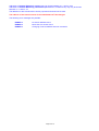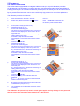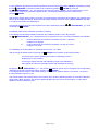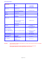
1
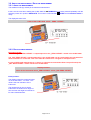
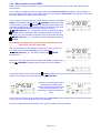
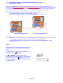
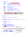
WYLER AG
Im Hölderli
CH-8405 WINTERTHUR
Switzerland
Tel.
Fax.
0041 (0) 52 233 66 66
0041 (0) 52 233 20 53
Homepage: http://www.wylerag.com
E-Mail:
[email protected]
USER's Manual
CLINOTRONIC 2000
File: „man_c20e.doc“
25.7.1999
PAGE
CONTENT
1. INTRODUCTION
1.1. DESCRIPTION OF THE CLINO 2000
1.2. STARTING
1.3. POSSIBLE CONFIGURATION
5
5
5
6
2. STARTING / HOW TO USE THE INSTRUMENT
2.1. DESCRIPTION OF PANEL FUNCTIONS
2.2. KEY FUNCTIONS
7
7
8
3. HOW TO USE THE CLINO 2000
3.1. CHECKING THE FUNCTIONS
3.2. ZERO-SETTING / ZERO ABSOLUTE AND ZERO VIRTUAL
3.3. SELECTING THE MEASURING UNIT
3.4. HOLD-FUNCTION
3.5. FUNCTION SEND (PRINT-FUNCTION)
3.6. TERMINATING A MEASUREMENT OR A SET UP
3.7. SELECTING A SENSOR OR AN INSTRUMENT
3.8. SELECTING CORRECT FILTER TYPE FOR VARIOUS APPLICATIONS
3.9. ABSOLUTE MEASUREMENT / RELATIVE MEASUREMENT
3.10. MEASURING BY SETTING LIMITS
3.11. DIFFERENTIAL MEASUREMENT WITH TWO CLINO 2000
11
11
12
16
17
18
21
21
21
22
24
25
4. ERROR MESSAGES
27
5. SERVICE
27
5.1. GENERAL
5.2. STORAGE
5.3. SPARE PARTS
5.4. CHANGING OF SENSOR ADDRESS
5.5. CALIBRATION
27
27
27
27
29
6. TECHNICAL DATA
33
Modifications:
Datum / Date
th
7 of July 2000
th
24 of Sept 2001
th
8 of Jan. 2003
Geändert durch
Modified by
HEH
HEH
HEH/MO
Beschreibung der Änderung
Description of modifications
New chapter “3.11. Differential measurement with two CLINO 2000”
Units page 14 modified
Index included
Page 2 of 33
INDEX
Key word
Chapter
Page
3.9.1
3.9
3.9
2.2.1
22
22
22
8
2.2.2
6
10
33
5.5
5.5
6
5.5.2
2.2.1
5.4
3.1
29
29
33
30
8
27
11
3.5
2.1
1.1
2.2.1
2.2.2
3.11
3.11
18
7
5
8
10
25
25
2.2.1
4.
4.
8
27
27
3.7
5.5.2
3.5
21
30
18
5.1
27
2.2.1
3.4
3.
3.5
9
17
11
19
2.2.2
1.
10
5
2.2
8
3.10
6
3.10
24
33
24
3.2.2
3.10
2.2.2
3.3
13
24
10
16
2.2.1
8
A
Absolute measurement
Absolute measurement / Relative measurement
Absolute measurement / Relative measurement
Automatic shut off deactivating
B
Battery display “BATT”
Battery lifetime
C
Calibration
Calibration
Calibration
Calibration principle
Cancelling any task
Changing of sensor address
Checking the functions
D
Data format of transmission
Description of panel functions
Description of the CLINO 2000
Description of the individual keys
Description of the panel
Differential measurement with two CLINO 2000
Differential-, resp. reference measurement with two CLINO 2000
E
ENTER-Key
Error messages
Error messages
F
Filter, selection
Fine calibration over the whole measuring range
Function SEND (Print-Function)
G
General
H
HOLD key
HOLD-Function
How to use the CLINO 2000
Hyper terminal program
I
Indicator of inclination direction
Introduction
K
Key functions
L
Limits
Limits of error
LIMITS, measuring with
M
Manual set-up of the virtual ZERO
Measuring by setting limits
Measuring units
Measuring units
O
ON/MODE - key
Page 3 of 33
P
Panel and display
Possible configuration
Power supply, external
2.11
1.3
6
7
6
33
5.5.1
29
3.11
2.2.1
3.3
3.5.2
3.9
3.1
6
3.2.1
25
8
16
22
22
11
33
12
3.7
3.8
3.3
2.2.2
2.2.1
3.7
2.2.2
2.2.2
5.4
5.
5
6
2.2.1
5.3
5.3
1.2
2.
5.2
5.2
21
21
16
10
8
21
10
10
27
27
27
33
8
27
27
5
7
27
27
6.
6
6
3.6
3.6
33
33
33
21
21
3.2.2
14
3.2
2.2.1
3.2
3.2.2
2.2.1
3.2
5.4
12
8
12
13
9
12
28
Q
Quick calibration
R
Reference, resp. differential measurement with two CLINO 2000
REL zero offset
Relative base length, measurement
Relative measurement
Relative measurement / absolute measurement
Reset
Resolution
Reversal measurement
S
Selecting a sensor or an instrument
Selecting correct filter type for various applications
Selecting the measuring unit
Selection pointer
SEND/ESC key
Sensor / instrument, selection
Sensor / Port A-B
Sensor address
Sensor address changing
Service
Service
Settling time
Shutting off the instrument
Spare parts
Spare parts
Starting
Starting / How to use the instrument
Storage
Storage
T
Technical data
Technical data
Temperature range
Terminating a measurement or a set up
Terminating a measurement or a set up
V
Virtual zero, automatic set-up
Z
ZERO absolute (with reversal measurement)
Zero offset
ZERO VIRTUAL
ZERO VIRTUAL
ZERO/SEL “+/-“ key
ZERO-Setting / ZERO absolute and ZERO virtual
ZEROTRONIC sensor
Page 4 of 33
1. INTRODUCTION
1.1. DESCRIPTION OF THE CLINO 2000
The CLINO 2000 was developed by WYLER AG as an intelligent display and measuring unit together with the
digital instrument’s family ZEROTRONIC. With this instruments all the sensors and instruments of the
ZEROTRONIC family can be used (See point 1.3 Configuration)
The CLINO 2000 is a
- Measuring instrument
- Display unit
On the CLINO 2000 a number of parameters can be changed and adjusted:
- Measuring unit
- Measuring mode
- Relative base length
and many more
The CLINO 2000 is compatible with the other instruments of the ZEROTRONIC family by using the RS485
serial communication. The measuring values may be transmitted to a printer or a PC/Laptop via RS232 output.
The measuring principle of the ZEROTRONIC family is based on a changing of the capacity of a condenser
built of two electrodes and a pendulum in form of a shield installed in between. The measured change of
capacity is directly influenced by the change of the inclination of the pendulum. This capacity change is the
primarily used signal for the angle to be measured. The measuring system is designed to be completely
antimagnetic. The basic signal received in the CLINO 2000 will be computed into an angle by comparing the
signal with a reference curve stored and then displayed in the required unit.
1.2. STARTING
Before working with the CLINO 2000 it is strongly recommended to carefully read this manual first.
This will avoid malfunctioning by making unsuitable manipulations like e.g. deleting the calibration data in the
sensor head etc.
Page 5 of 33
1.3. POSSIBLE CONFIGURATION
Stand alone unit
Two units connected for remote display or differential mode / max. 15m
CLINO 2000 connected with ZEROTRONIC Sensor / max. 15m
CLINO 2000 connected to a PC / RS232
Page 6 of 33
CLINO 2000 connected with a MINILEVEL or LEVELTRONIC „NT“ for differential mode
All the above configurations can be used. For specifications of the sensors and the instruments see the
respective data sheets.
2. STARTING / HOW TO USE THE INSTRUMENT
2.1. DESCRIPTION OF PANEL FUNCTIONS
2.1.1. PANEL AND DISPLAY
Page 7 of 33
2.2. KEY FUNCTIONS
2.2.1. DESCRIPTION OF THE INDIVIDUAL KEYS
ON/MODE - Key
Function - 1 -
Pressing the
ON/MODE key starts the CLINO 2000. When keeping the key
pressed all the LCD elements are lighted. After releasing the key the instrument
switches to the measuring mode and the calibration data of the internal sensor has
been collected. After a short period of time the actual angle will be displayed in the
last used measuring unit. In case of trouble an error message will be displayed.
(See point 4)
ON/MODE key for more than 3 seconds the display starts
When pressing the
flashing and the automatic shut off is disabled. In the standard mode the
instrument shut off after about 5 minutes. To turn off the instrument press the
ON/MODE key for more than 3 seconds until the display disappears.
Exeption: In case the instrument is powered by an external power supply, the
instrument is never shutting off automatically.
Function - 2 -
ON/MODE is also used for moving the selection pointer on the lower
The
display area. By pressing this key the selection pointer moves from one position to
the next.
Function - 3 -
ON/MODE key needs to be pressed for
For shutting off the CLINO 2000; the
3-4 seconds until the displayed figures disappear.
Function - 4 -
Used for „ZERO-Setting“ of saved (memory) values in the function „REL ZERO“.
ON/MODE key, the
To set the memory in this function to ZERO press the
displayed values will become ZERO. This has to be confirmed by pressing
ENTER
ENTER – Key
The key
function.
ENTER is used to save an entered value or to accept a selected
SEND/ESC- Key
Function - 1 -
SEND is used for the transmission of a measuring value through the
The key
RS232 port or to send the value to a printer or another connected system. Through
the same port the values may also be transmitted to a PC or Laptop for further
treatment of the data.
Function - 2 -
Also used for canceling any „HOLD“ function and return to the measuring mode.
Function - 3 -
Canceling any task not yet finished.
Page 8 of 33
ZERO/SELECT "+/-" - Key
The key
ZERO "+/-" can be used to change a number of possible
parameters like e.g.
Measuring units
Measuring units, respectively ports ( „A“ / „B“ / „A+B“ / „A B“ )
Changing of the measuring range
Changing of the instruments address
Set up the relative base length
Set up of the „Zero-Offset“
Set up of the „REL Zero-Offset“
etc.
HOLD - Key
Function - 1 -
HOLD key a measured value may „frozen“. This value will be
With the
SEND the CLINO 2000 will return to the
displayed until by pressing the key
measuring mode.
Function - 2 -
When using the mode REL ZERO and ZERO the actual measuring value can
be accepted by pressing the
HOLD key
Page 9 of 33
2.2.2. DESCRIPTION OF THE PANEL
Main
display
The actual measuring values of an active sensor/instrument are displayed. By using the
mode „SENSOR“ other sensors or instruments connected at port B may be selected,
differential measurement may be applied.
Indicator of
inclination
direction
The pictograph indicates the direction of the inclination
declining to the right (negative angle)
inclining to the right (positive angle)
Selection pointer
With the selection pointer the intended function can be chosen:
SENSOR
Select the active sensor/port
ABSOLUTE
Absolute measuring mode
REL ZERO
Relative measuring mode
UNIT
Selection of measuring units
ZERO
Set absolute zero
LIMITS
Output of control signals
FILTER
Adjustment of filter type
ADDRESS
CALIB
ONLINE
Display and changing of sensor
addresses
Calibration of sensors
Display of active communication
through port
Battery display
"BATT"
When the battery power is low, the sign "BATT" is constantly on
Measuring units
The actual measuring unit is displayed. 10 basic units are available
and most of them can in addition be changed into subunits.
Sensor/port A-B
Function - 1 -
The connection/port is displayed for
information concerning:
- the displayed measuring value
- active sensor/instrument for
calibration
purposes
Function - 2 -
Shows the measuring mode e.g.
individual measuring or differential
measuring (A-B)
Sensor address
The active sensor address is displayed
Page 10 of 33
3. HOW TO USE THE CLINO 2000
3.1. CHECKING THE FUNCTIONS
The key
ON/MODE can be pressed. As long as this key is pressed all elements of the LCD display will show
up. After releasing the key the mode is switched to the measuring mode. The active signal is displayed in the
last used measuring unit. During the reading of the calibration data six small „o“ will be displayed.
The following display variations are correct:
When now the connected instrument or sensor is tilted, the displayed value must change accordingly.
If a second instrument or an additional sensor has been connected to port B, a respective message may appear
if some errors are noted:
The following error messages are possible:
ERROR 0
Instrument is defect, to be sent to the service center
ERROR 1
No sensor or instrument connected, or not properly installed
ERROR 2
No measurement has been done so far with the connected sensor/instrument.
The sensor must be addressed correctly (See point 3.7. Selecting a sensor or
an instrument)
ERROR 3
Calibration data not available. The display shows the malfunctioning item (port
and address) also possible when the battery power is not sufficient
(Communication with sensor not possible)
For other error messages see point 4
To reinstall the basic set up a RESET may be done at any time. The procedure is as follows:
ON/MODE and
ENTER must be pressed simultaneously for at least one second. All the
Both keys
manually installed data is lost and the CLINO 2000 will be set to the following basic standards:
Basic standards:
Measuring mode:
Measuring unit:
Relative Base:
ZERO-OFFSET absolute:
Sensor:
Filter
absolute
the next possible and useful unit
1000 mm
remains intact
PORT A, no Sensor (ERROR 2)
No 5
Immediately after RESET the error message 2 is displayed. This means the connected sensor must be
addressed correctly from new. (See point 3.7. Selecting a sensor or an instrument)
Page 11 of 33
3.2.
ZERO-SETTING / ZERO ABSOLUTE AND ZERO VIRTUAL
Remarks:
Using ZERO SETTING two different tasks can be realized:
a) ZERO ABSOLUTE / The instrument shows "0" when the angle of the mounting surface is exactly
positioned in the direction of the center of the earth.
b) ZERO VIRTUAL / The instrument shows "0" at any predefined angle.
3.2.1. ZERO ABSOLUTE (WITH REVERSAL MEASUREMENT)
The ZERO absolute is the basis for all the inclination measurements in the absolute mode. For such a
measurement if high precision is required, it is of utmost importance that the object to be measured and the
CLINO 2000 are both at the same temperature level. The CLINO 2000 should have been turned on a few
minutes before the measurement procedure. For this procedure a suitable surface must be chosen (rigid, flat
and as horizontal as possible). On this surface the CLINO 2000 must be placed; the exact position of the
instrument is to be marked on the surface.
The ZERO absolute will automatically be set by applying the
reversal measurement. (Taking two measurements on the
same spot but in the 180° opposite direction) For this procedure
a suitable surface must be chosen (rigid, flat and as horizontal
as possible). On this surface the CLINO 2000 must be placed,
the exact position of the instrument is to be marked on the
surface.
The „ZERO-OFFSET“ is stored in the CLINO 2000
EXAMPLE:
The selection pointer of the CLINO 2000 must now be placed
ON/MODE key
below the marking ZERO by pressing the
several times. If the required position is reached, it must be
ENTER. On the display the last set
confirmed by pressing
„Zero-Offset“ (Basic offset) will be displayed. The direction
indicator (+/-) is flashing.
The CLINO 2000 must now sit at position one and after a few
HOLD, the
seconds settling time allowed, by pressing the key
first reading is collected. This first value is displayed and the
selection pointer below ZERO is flashing which means the second
reading is expected.
The CLINO 2000 must now be rotated horizontally by 180° and
placed exactly on the same spot. After a few seconds settling time
the key
HOLD must be pressed again for collecting the
second reading.
The computed „Zero-Offset“ (Basic offset) is now displayed on
the CLINO 2000.
(The displayed „Zero-Offset“ is calculated by adding the two
readings and dividing the result by two.)
Page 12 of 33
If this „Zero-Offset“ (Basic offset) must now be saved,
ENTER must be pressed. Immediately after
the key
this, the selection pointer jumps to the measuring mode
absolute and the measuring result under consideration
of the „Zero-Offset“ (Basic offset) will be displayed.
The „Zero-Offset“ (Basic offset) computed by applying the reversal method is the deviation of the instrument’s
ZERO to the absolute ZERO. The display on the CLINO 2000 therefore is the:
Displayed value =
Value of the CLINO 2000 minus „Zero-Offset“.
The reversal measurement to establish the exact „Zero-Offset“ (Basic offset) should be done periodically if high
quality measurements are required. Especially after longer intervals the method is useful.
3.2.2. ZERO VIRTUAL
I) Manual set-up of the virtual ZERO
One possibility of using ZERO virtual means to establish an artificial plane, respectively angle, to be chosen as
absolute zero.
Another possibility is to change the existing „Zero-Offset“ (Basic offset) of the CLINO 2000 e.g. established by
means of using the reversal method.
Only well skilled and trained user should make use of this feature!!!
Example:
Initial position:
The display on the CLINO 2000
shows the measured value of
+0°07‘20‘‘. This value is the true
inclination of the instrument.
Only one sensor (internal sensor of the CLINO 2000 or the external sensor connected to Port “B”) at a time can
be set to ZERO virtual. This sensor must be selected first.
The selection pointer must be moved below the marking ZERO in the display of the CLINO 2000 by pressing
the key
ON/MODE several times. If reached the selection must be confirmed by pressing
ENTER.
The last computed or manually entered value „Zero-Offset“
(Basic offset) is displayed. In our example 00° 00‘ 00‘‘
The direction indicator is flashing
This displayed value may now be changed manually by
ZERO/SELECT „+/-“ to the desired
applying the keys
value.
e.g. from +0° 00’ 00’’ to new +0°07‘20‘‘
The direction indicator is flashing
The value is now the new „Zero-Offset“
Page 13 of 33
If this so manually established „Zero-Offset“ must now be
ENTER must be pressed. The new „Zerosaved the key
Offset“ is now saved in the CLINO 2000. Immediately after this,
the selection pointer jumps to the measuring mode absolute
and the measuring result under consideration of the new
„Zero-Offset“ will be displayed. The following new value will
now be displayed in the absolute mode:
„ZERO-OFFSET“ is stored in the CLINO 2000
Displayed value =
Value of the CLINO 2000 minus „Zero-Offset“.
Remarks:
Until the input is confirmed by using the
stopped any time by pressing
ENTER key, every manipulation can be
SEND/ESC
Result:
Despite the fact that CLINO 2000 is
still placed at the same angle the
display of the instrument now shows
the value 0°00‘00‘‘ This is the so
called virtual ZERO
This new virtual ZERO is the
reference for all the future
measurements based on this angle
(originally 0°07‘20‘‘)
II)
Automatic set-up of the virtual ZERO
Practically quite often a measuring surface is not absolutely horizontal but should be the reference plane for
other measurements. In these cases it is useful to set the basic value for this surface to: 0°00’00‘‘
This can be done by manually setting the virtual zero as described before or by automatically define the value
with the CLINO 2000 set-up. (It is done by using a reversal measurement mode without turning the instrument
180 deg.)
Procedure:
Initial position:
The display shows the measured
value on the CLINO 2000 :
+0°09‘16‘‘. This value is the true
inclination of the CLINO 2000.
The selection pointer must be moved below the marking ZERO in the
display of the CLINO 2000 by pressing the key
ON/MODE several
times. If reached the selection must be confirmed by pressing
ENTER.
The last computed or manually entered value „Zero-Offset“. The
direction indicator is flashing
Page 14 of 33
The CLINO 2000 must now sit at position one and after a few
seconds settling time allowed, by pressing the key
HOLD,
the first reading is collected. This first value is displayed and the
selection pointer below ZERO is flashing which means the
second reading is expected.
After a few seconds settling time the key
HOLD must be pressed again for collecting the second reading.
The instrument remains at the same position without turning 180°.
The newly computed „Zero-Offset“ is now displayed on the
CLINO 2000
(The displayed „Zero-Offset“ is calculated by adding the two
readings and dividing the result by two.)
ENTER must
If this „Zero-Offset“ must now be saved, the key
be pressed. Immediately after this, the selection pointer jumps to
the measuring mode absolute and the measuring result under
consideration of the „Zero-Offset“ (Basic offset) will be
displayed.
The „ZERO-OFFSET“ is stored in the CLINO 2000
Displayed value =
Value of the CLINO 2000 minus „Zero-Offset“.
Remarks:
Until the input is confirmed by using the
time by pressing
ENTER key, every manipulation can be stopped at any
SEND/ESC
Result:
Despite the fact that the
CLINO 2000 is still placed at the
same angle the display of the
instrument now shows the value
0°00‘00‘‘ This is the so called
virtual ZERO
This new virtual ZERO is the
reference for all the future
measurements based on this angle
(originally 0°09‘16‘‘)
Remarks:
Please see also "Relative measurement" Chapter 3.9.2
Page 15 of 33
3.3. SELECTION OF THE MEASURING UNIT
The desired measuring unit can be selected by repeatedly pressing the key
ON/MODE until the selection
ENTER is pressed.
pointer is below the function UNIT and then the
ZERO/SELECT "+/-" until the desired unit
The possible formats may now be chosen by pressing the key
ENTER. The selection remains valid until
is displayed. This selection must be confirmed by pressing
changed in the same manner as described above.
The following measuring units can be chosen:
xxx° xx'
xx° xx' xx"
xxxx' xx"
xxx.xxx°
xxx.xx
xxx.xx
xx.xxxx
xxx.xx
xxxx.xx
xx.xxxx
xx.xxxx
xxxx.xx
xxx.xxx
DEG
DEG
DEG
DEG
%o
A %o
"/REL
mm/REL
mRad
"/12"
"/10"
mm/m
GON
Deg / Min
Deg / Min / Sec
Min / Sec
Degree, 3 decimal
‰, 2 decimal
Artillerie-Promille
mm per relative base, 4 decimal
mm per relative base, 2 decimal
Milliradian, 2 decimal
Inch per 12 Inch, 4 decimal
Inch per 10 Inch, 4 decimal
mm per m, 2 decimal
New degree, 3 decimal
For a measurement with relative base length the selection
ON/MODE
pointer must be moved by repeatedly pressing the
ENTER.
key to the position UNIT. Confirm with
ZERO/SELECT "+/-" the desired unit
By using the keys
can now be chosen (mm/REL or inch/REL) The selection must be
ENTER.
confirmed with the key
On the display the direction indicator is flashing alternatively plus
or minus; the existing base length is shown (Standard length is
1000 mm or 10")
ENTER this value may be accepted or with
By pressing
ZERO/SELECT „+/-“ the relative base length may be
adjusted as required and then finally confirmed with
ENTER.
In the relative mode the angle is related to the height "X" as the
elevation over the set relative base length in the chosen
unit (in mm, or Inch).
Exception:
RESET (see point 3.1)
Page 16 of 33
3.4.
HOLD-FUNCTION
This function is available in all measuring modes.
Place the CLINO 2000 on a flat stable surface. Use the key
HOLD. While the CLINO 2000 waits for a valid
measurement (two identical values in succession) the display
will show "oooooo". As it is practically impossible for two
successive values to be identical while the instrument is
handled, the instrument may be positioned after the key is
depressed.
As soon as the condition for a valid measurement is fulfilled,
the measuring value is displayed, the direction indicator
flashing. To read the measurement value, the CLINO 2000
may be removed from its located position. The display value is
"frozen".
SEND/ESC. If a printer is connected, the
Use the key
measured value will be transmitted and the CLINO 2000 will be
ready for use in the normal mode If you just want to read the
value,
SEND/ESC again will return to the standard mode.
pressing
If HOLD is required for the next measurement, it is possible
without canceling; directly to recall
HOLD again.
Remarks:
The level of vibration at the measuring location considerably influences the time necessary to
collect a valid measurement. Severe vibration may even completely prevent the condition (two
identical values in succession), necessary to register a true measurement.
In order to regain measuring capability under this condition, take the instrument to an object with
a lower vibration level and complete the operation in process. By key using
SEND/ESC the
further procedure may be cancelled immediately. The displayed value may now be accepted or
the process must be repeated.
If after 60 seconds no value was accepted, the „ERROR 7“ message is displayed.
HOLD function has not been successfully completed within 60 seconds. The procedure
needs to be repeated.
By using the function RESET the CLINO 2000 will return to the standard settings. With the
exception of the calibration data all previous adjustments are lost!!
Page 17 of 33
3.5. FUNCTION SEND (PRINT-FUNCTION)
Using the key
SEND/ESC will send the displayed value through the port "RS 232" to a connected PC, or
Laptop via the RS232 port. This function can also be used in combination with
HOLD in order to transmit the
„frozen“ value.
The function SEND may be activated from a connected PC/Laptop by transmitting a letter „P“ (as letter) through
the serial port RS 232
DATA FORMAT OUT-PORT
Measurement active
MessMode_A
MessMode_B
MessMode_A_minusB
MessMode_A_B
[sss Aaaa sn.nnnnnn<cr>]
[sss Baaa sn.nnnnnn<cr>]
[sss Aaaa-Baaa sn.nnnnnn<cr>]
[sss Aaaa sn.nnnnnn Baaa sn.nnnnnn<cr>]
sss = 0 .. 255 - Continuous no.
aaa = Sensor Address 1..255 (e.g. 004) / ML/LT NT 1-32
sn.nnnnnn = +9.999999 - Positive Overrange
-9.999999 - Negative Overrange
other value - Angle in rad e.g. +0.226349
Menue aktive or error ( -0.000000 means no data available)
MessMode_A
MessMode_B
MessMode_A_minusB
MessMode_A_B
[9xy Aaaa -0.000000<cr>]
[9xy Baaa -0.000000<cr>]
[9xy Aaaa-Baaa -0.000000<cr>]
[9xy Aaaa -0.000000 Baaa -0.000000<cr>]
aaa = Sensor Address 1..255 resp. 0 when address undefined
x = 0 - General error
1 - Port A error
2 - Port B error
y = 0 - Menu active (no error)
>0 - Error codes (According to manual)
Format of transmission
asynchrony, 7Bit, 2 Stopbits, no parity
Page 18 of 33
Example using the Hyper Terminal of Windows NT or Windows Terminal program
(Example is WIN NT)
1. Open the Terminal-Program in
Windows / Accessories. and insert a
name
Confirm with OK
2. Enter the serial port definition
connected to the CLINO 2000.
Confirm with OK
3. Enter the parameters
Bits per Second:
Data bits:
Parity:
Stop bits:
Protocol:
9600
7
no
2
no
Confirm with OK
The HyperTerminal-Windows
appear.
Repeatedly pressing the key
SEND/ESC the actual value will
be transmitted in [Rad]
Alternatively the value can be called
by pressing the key "P" on the PC
keyboard.
Page 19 of 33
CLINO 2000 with address 50 connected to port "A"
Meaning of the
display:
068
A050
-0.000100
Continuous number.
(3 measurements per
second are performed)
Port „A“, address 50
- 0.000100 Rad
resp.-100 µRad
CLINO 2000 with address 50 is connected to port "A",
one external sensor with address 21 is connected to port "B" / Measuring mode: A & B alternatively
measured
Meaning of the
display:
031
Continuous number.
A050
Port „A“, address 50
-0.000104
B021
+0.001079
- 0.000104 Rad
resp.-104 µRad
Port „B“
address 21
+0.001079 Rad
resp.+1079 µRad
CLINO 2000 with address 50 is connected to port "A",
one external sensor with address 21 is connected to port "B" / Measuring mode: A - B differential
measurement
Meaning of the
display:
141
A050 – B021
-0.001144
Continuous number
Measuring mode
Differential mode
Port „A“ CLINO 2000
with address 50 minus
Port „B“ sensor with
address 21
Difference
Sensor [A] – [B]:
- 0.001144 Rad
resp.-1144 µRad
Page 20 of 33
3.6. TERMINATING A MEASUREMENT OR A SET UP
In case of the required canceling of a measuring procedure or the changing of parameters the process may be
SEND/ESC. This is true only as long
ended at any time and the previous state will be installed by pressing
as no change has been accepted by pressing
ENTER before.
3.7. SELECTING A SENSOR OR AN INSTRUMENT
With the CLINO 2000 the possibility exists to display the measured values of the instrument itself as well as the
difference between the instrument and an additional instrument or a connected sensor ZEROTRONIC. In case
of the differential measurement the second instrument must be connected to the port B (External sensor B). It is
not possible to measure the difference of two sensors connected to the same port.
Basically the following set-up is possible:
- Measurement of the CLINO 2000 (= internal sensor A, corresponding to Sensor/Port A)
- Measurement of one or more instruments connected to port B
- Differential measurement between the CLINO 2000 and another instrument at port B
- Alternating display of the CLINO 2000 and an instrument connected to port B
For differential measurement respectively measurement
with a reference CLINOTRONIC 2000 see chapter
”3.11. Differential- respect. Reference Measurement with two CLINOTRONIC 2000”
For choosing the measuring mode and the address of the
ON/MODE key must be pressed
sensors connected the
repeatedly until the selection pointer is below SENSOR and
ENTER. The possibilities "Port A",
accepted by pressing
"Port B", "Port A-B" or "Port A B" may be selected by
ZERO/SELECT "+/-" The desired
applying the key
selection can be accepted by pressing
ENTER. After this
the CLINO 2000 is looking for all the connected sensors
respectively their address. Up to 255 sensors may be
connected. The address of the first sensor will be displayed
flashing. During the searching procedure the frame of the
„Sensor address“ will flash in circular motion below the
selected port.
If more than one sensor is connected to the port B, the one
ZERO/SELECT
desired can be selected by pressing
and confirmed with
ENTER.
In case of differential measurement between two sensors the
same procedure must be repeated for port B.
After pressing
ENTER the respective measurement starts.
3.8. SELECTING CORRECT FILTER TYPE FOR VARIOUS APPLICATIONS
A number of different types of filters are incorporated. The standard factory setting is filter type no 5. To change
this setting the selection pointer must be moved below „Filter“. After pressing
ENTER the actual setting is
displayed. The number may be changed from 1 to 10 by using the + or - arrows and then be confirmed by
pressing
ENTER.
The most suitable type of filter is best found out by practically testing, as the measuring conditions have quite an
influence. Generally spoken it can be said that the lowest figure (almost no filter) sends the collected signals
rapidly to the display possibly resulting in an unstable display. The maximum filter (No. 10) mathematically
treats the signal by collecting data and sending somewhat delayed a signal integrated over a period of time.
Page 21 of 33
3.9. ABSOLUTE MEASUREMENT / RELATIVE MEASUREMENT
3.9.1. ABSOLUTE MEASUREMENT
The standard mode (by default) is the absolute measurement.
ON/MODE key must be pressed repeatedly until the
If this is not the case when starting the CLINO 2000 the
ENTER and the absolute mode is
selection pointer is in position ABSOLUTE. This must be confirmed with
ready.
The displayed value is the
Value of the CLINO 2000 minus „ZERO - OFFSET“
3.9.2. RELATIVE MEASUREMENT
Important remark:
The defined „REL ZERO OFFSET“ is superimposed on the „ZERO-OFFSET“ stored in the CLINO 2000.
The „REL ZERO OFFSET“ stored temporarily in the CLINO 2000 can be recalled with any time when the
same instrument is connected. This value must be confirmed or changed for example to zero.
In case of differential measurement ( 1 Sensor or instrument connected to Port A an port B each) the
„REL ZERO OFFSET“ will be stored in the CLINO 2000.
Displayed value =
Value of the instrument minus „ZERO-OFFSET“ minus „REL ZERO OFFSET“
Initial position:
The display shows the measured value
on the CLINO 2000 : +0°10‘00‘‘. This
value is the true inclination of the
instrument.
The requirement is now to set the
instrument's inclination at an angle of
zero and use this angle as a reference
for future measurements.
Page 22 of 33
The selection pointer must be moved below the marking
REL ZERO in the display of the CLINO 2000 by pressing the
ON/MODE several times. If reached the selection must
key
ENTER.
be confirmed by pressing
The last computed or manually entered value „REL ZERO
value“, in our example 0° 00'‘00'‘ The direction indicator is
flashing
The CLINO 2000 must now be at the correct position and after a
few seconds settling time allowed, by pressing the key
HOLD, the reading is collected. This value )"REL ZERO
OFFSET") is displayed.
ENTER. This relative
Should this value no be stored press
zero value is stored in the CLINO 2000. The display jumps into
the measuring mode "REL ZERO", the display is 0°00‘00‘‘ and
the measurement continues by considering the "REL ZERO
OFFSET"
As an alternative the value can also be changed manually by
ZERO/SELECT "+/-" before confirming
using the key
ENTER
with
Result:
Despite the fact that the CLINO 2000
is still placed at the same angle the
display now shows the value
0°00‘00‘‘ (Fig. 1)
This new relative zero is the
reference for all the future
measurements based on this angle
(originally 0°10‘00‘‘)
Fig. 1
The selection pointer of the CLINO
2000 can now be placed below the
marking ABSOLUTE by pressing the
ON/MODE key several times to
return to the absolute measuring
mode. After confirming with
ENTER the original value is
displayed. (Fig. 2)
Fig. 2
The values stored in the stacks of „ZERO“ and „Relative Zero“ can be deleted as follows:
ON/MODE key repeatedly until the selection pointer is located under "REL ZERO"
Press the
ENTER. In the display the existing value is seen. By using the key
or "ZERO" and confirm with
ZERO/SELECT "+/-" the value can be set to "0". This can now be confirmed with
ENTER and the CLINO 2000 starts in the measuring mode. The stack is empty.
Page 23 of 33
3.10. MEASURING BY SETTING LIMITS
When your task requires the indication of a surpassed measuring value with an "alarm" the LIMITS function
must be used.
In this mode it is possible to define an upper and a lower measuring limitation (LIMITS). After installation of
the limits a signal will be seen on the screen and also sent through the port RS 232 if the measured value rises
above the upper limit or falls below the lower limit.
For the setting of limits the selection pointer must be moved to the position
ON/MODE. If reached it needs
LIMITS by repeatedly pressing the key
ENTER. In the display of the CLINO 2000
to be accepted by pressing
a possible installed lower limit is displayed with a marking LO. This value
may now manually be adjusted to the required value by using
ZERO/SELECT „+/-“. If reached it must be accepted by pressing
ENTER. After this the upper value is displayed with the marking HI.
This value may now manually be adjusted to the required value by using
ZERO/SELECT „+/-“. If reached it must be accepted by pressing
ENTER.
ATTENTION: The upper limit (HI) must always, absolutely seen, be
higher than the lower limit (LOW)
After the confirmation in the display the upper limit is seen (remark HI)
This value can be changed manually by using the keys
ZERO/SELECT „+/-“ and after confirming with
ENTER
the limit is set.
After the saving of the upper limit the display shows OFF or ON. By using
ON/MODE the display jumps between the two possibilities.
the key
ENTER. (Means: limits ON or limits OFF) If the limits must not be
The desired mode must be confirmed with
SEND/ESC
stored, the procedure can be cancelled by using
If during a measurement the limits
are reached the display starts
flashing, alternatively the measured
value and the remark HI or LO
depending on the limit reached are
seen.
At the same time two signal will be transmitted to the port RS 232. The first signal may be used for an external
control action or a relay (12V/500 mA) may be activated.
The second signal transmits the polarity of the signal in relation to the set limitation.
Page 24 of 33
3.11. DIFFERENTIAL-, RESPECT REFERENCE MEASUREMENT WITH TWO
CLINOTRONIC 2000
Applying differential measurement respectively reference measurement means by definition using two
instruments, a Measuring Instrument (A) and a Reference Instrument (B), whereas the difference between
the two angles is of interest (A-B). This difference remains unchanged when the same angular change is
applied on both instruments. This measurement is a special form of a relative measurement.
The differential measurement has the greatest advantages in the following tasks:
Measurements made on objects under influence of vibration
Measurements made on objects and systems not rigid enough (unstable, flimsy)
Measuring Instrument (A)
Reference Instrument (B)
Preconditions:
• Both instruments are powered by either internal batteries in each instrument or by using an external
power supply connected to one of the two instrument’s free socket “RS232”
• Both instruments are connected together using the ports “EXTERNAL SENSOR (B)”, with a
bus cable (max. 1000 m)
Start-up
Both instruments are placed in position and properly
connected and power supply installed as mentioned
above.
First the Reference instrument must be started by
ON/MODE.
pressing the button
ON/MODE key must now be pressed
The
repeatedly until the selection pointer is below ONLINE
and accepted by pressing
ENTER. The display
shows now “REF” what means that the instrument is in
the reference mode.
Page 25 of 33
Secondly the Measuring instrument must be
ON/MODE.
started by pressing the button
ON/MODE key must now be pressed
The
repeatedly until the selection pointer is below
SENSOR and confirmed by pressing
ENTER.
The "Port A-B" must be selected for choosing
differential mode, applying the key
ZERO/SELECT "+/-" until the desired
selection is displayed, then accept by pressing
ENTER. After this the CLINO 2000 is looking
for all the connected sensors respectively their
address. The correct addresses of (A) and (B)
must be confirmed with
ENTER.
Remarks:
When the differential mode is selected for the
first time with the two respective instruments all
the calibration data must be collected and
computed, this task will usually take up to two
minutes time. After this the start-up time will be
usually be reduced to approximately 20 to 30
seconds.
On the display of the measuring instrument the
measuring result (value of measuring instrument
minus value of reference instrument, A-B) is now
seen.
As long as the installed configuration remains the
ON/MODE key must be
same only the
pressed on the two instruments for a renewed
start-up.
Page 26 of 33
4. ERROR MESSAGES
ERROR 0
Instrument’s fault, needs to be sent to the service center
ERROR 1
Sensor(s) /Instrument(s) not connected, or not correct address
ERROR 2
No measuring has been made with the connected sensor. The sensor
must be addressed first (See point 3.7. Selecting a sensor or an
instrument)
ERROR 3
No calibration data available (the respective sensor/port is displayed)
ERROR 4
No sensor address found
ERROR 5
More than one sensor found
ERROR 6
Changing of sensor address was not successful
ERROR 7
HOLD function has not been successfully completed within 60
seconds. The procedure needs to be repeated.
Battery not correctly installed
ERROR 8
It was not possible to save the calibration data successfully in the
sensor head
ERROR 9
Remarks:
After the error message is displayed and confirmed with
jumps to the position SENSOR (select sensor)
ENTER the position indicator
5. SERVICE
5.1. GENERAL
The CLINO 2000 needs no special service other than the regular cleaning.
5.2. STORAGE
The CLINO 2000 should be stored in a save place, best in the transportation case. For longer storage periods it
is recommended to remove the batteries.
5.3. SPARE PARTS
The following spares are available:
- Batteries
- Cables
5.4. CHANGING OF SENSOR ADDRESS
Move the position indicator to the position ADDRESS by
ON/MODE and confirm the
repeatedly pressing the key
setting with
ENTER. If only one sensor is connected as
described above the respective port and address number is
displayed flashing.
Remarks:
If more than one sensor is connected, the error message ERROR 5 is displayed. (More than one sensor found)
ZERO/SELECT the new address can
Using the keys
be entered and confirmed by pressing
ENTER. If the
procedure was successful the measurement starts with the
newly given address.
Page 27 of 33
Addresses of external Zerotronic sensors may be chosen between no. 1 and no. 254
Addresses of external Measuring instruments (Minilevel NT, Leveltronic NT) may only be chosen
between no. 1 and no. 32
The address no 255 is reserved for service purposes and should not be used.
The address of the internal sensor of the CLINO 2000 can’t be changed.
The following error messages are possible:
ERROR 4
No sensor address found
ERROR 5
More than one sensor found
ERROR 6
Changing of sensor address was not successful
Page 28 of 33
5.5 CALIBRATION
5.5.1 QUICK CALIBRATION
The CLINO 2000 is equipped with an integrated calibration set-up for a quick calibration procedure.
On the backside of the instrument a number of precisely manufactured and placed holes are available for
installing the dowel pins as calibration aids. These pins are part of the delivery and can be inserted into the
holes. With the quick calibration method the values at + and - 45° as well as the exact zero value can be fixed.
By this procedure the instrument can be set to a sufficiently high precision for most of the applications.
The calibration procedure is as follows:
1.
Start the instrument in the mode „Absolute“
Point 3.9.1
2.
Select menu „ZERO“ and confirm with
Press
ON/MODE several times until
the selection pointer is below ZERO
3.
Press „MODE“ shortly (less than 5 sec.)
4.
Adjustment of angle at +45°,
Pre-set value will be displayed
The dowel pins are to be inserted in such a way that the
instrument would display +45° when two pins are on a
horizontal plane.
E.g. hold the instrument on the side of a measuring and
setting plate, the pins on top.
Press HOLD, keep the instrument stable
First displayed is oooooo, then the measured value is
seen.
Confirm with
ENTER
5.
Adjustment of angle at 0°,
Pre-set value will be displayed
The dowel pins are to be inserted in such a way that the
instrument would display 0° when two pins are on a
horizontal plane.
E.g. hold the instrument on the side of a measuring and
setting plate, the pins on top.
Press HOLD, keep the instrument stable
First displayed is oooooo, then the measured value is
seen.
Confirm with
ENTER
6
.
7.
ENTER
Adjustment of angle at -45°,
Pre-set value will be displayed
The dowel pins are to be inserted in such a way that the
instrument would display -45° when two pins are on a
horizontal plane.
E.g. hold the instrument on the side of a measuring and
setting plate, the pins on top.
Press HOLD, keep the instrument stable
First displayed is oooooo, then the measured value is
seen.
Confirm with
ENTER
During the sampling of the collected values first
displayed
is: . . . . . ., then oooooo, at the end it will automatically
switch in the measuring mode
8.
By applying a reversal measurement set the instrument
to absolute zero (see point 3.2.1)
9.
The CLINO 2000 is now calibrated and can be used for
measuring.
The calibration aids (dowel pins) must be stored grease applied and any damage is to be prevented.
Also the holes in the instrument must remain free of dust and dirt.
Page 29 of 33
5.5.2 FINE CALIBRATION OVER THE WHOLE MEASURING RANGE
The fine calibration may be required when
- the existing calibration was lost
- the accuracy is not sufficient anymore
- a connected sensor or the measuring range has changed
For such a calibration procedure a precise sine bar or an accurate index table should be available.
Remarks:
In order to guarantee the precise functioning of the instrument a minimum of seven calibration
points are required over the whole measuring range.
Principle of the calibration method
The bases of all the measurements with digital technology like the CLINO 2000 and the connected
sensors/instruments are the calibration data stored in the sensor heads. Throughout the whole measuring range
a number of reference calibrating points are stored in the sensor heads. The linearity of the measuring range
depends on the number of these reference-calibrating points. Each measured angle delivers a signal in form of
a frequency and to these reference frequencies the respective calibration points are matched. From these
values a calibration curve will be established.
The measured angles between these calibration points are computed by interpolation and displayed on the
screen in the desired measuring unit.
All sensors/instruments leaving the factory at WYLER’s are calibrated according the measuring range and have
undergone a severe quality test procedure.
Page 30 of 33
For the calibration procedure the selection pointer must be moved to the position CALIB by repeatedly pressing
the key
ON/MODE. If reached it needs to be accepted by pressing
ENTER. By using the
ZERO/SELECT „+/-“ the respective port may be chosen. „Port A“, for the internal sensor in the
key
CLINO 2000, „Port B“ for a possible external sensor. The selected possibility must be confirmed by
ENTER.
pressing
After this the CLINO 2000 is looking for all the connected sensors respectively their address. The address of the
sensor will be displayed flashing. During the searching procedure the frame of the „Sensor address“ will flash
in circular motion below the selected port.
Are several sensors connected the required one must be selected by the key
ENTER.
confirmed with
ZERO/SELECT „+/-“ and
Immediately after this the calibration procedure is starting.
In the display the last entered distance between two calibration points is seen. By using the
key
ZERO/SELECT „+/-“ this distance may be entered from new. Two basic possibilities are available:
I)
II)
Choose calibration point distance is between 0.5 and 7.5 degrees,
in steps of 0.5 degrees.
Choose calibration point distance is between 1.0 and 15.0 mm/m,
in steps of 1.0 mm/m.
For calibrating the CLINO 2000 it is recommended to use 5° 7.5° steps.
After choosing the distance and confirming with
ENTER the procedure continuous as follows:
- In the area of the sensor address the number of calibrating points is
displayed (incl. zero position)
- In the major display area the total calibration range to be calibrated is
seen (Result of number of calibration points and the distances chosen).
By applying
ZERO/SELECT „+/-“ the number of calibration points may be changed. The corresponding
ENTER.
calibration range will automatically adjust. Confirm with
In the display the first angle to set is seen flashing. In the window „Address Sensor“ the number 1 is seen for
the first calibration point to be set.
The CLINO 2000 or the external sensor must now be set to the first calibrating position on a suitable calibration
gauge (rotary table, sine bar). This angle is displayed flashing on the screen and the figure 1 is seen which
stands for the first calibration point.
Page 31 of 33
If the correct position is installed and a few seconds settling time were allowed the value can be saved by
ENTER. During the reading of the data the display remains stable. After successful reading the
pressing
next calibration point will be displayed and the respective procedure must continue.
Example
Result
Measuring range of CLINO 2000
+/- 45 degrees
Distance between the calibrating points
5.000 degree
Number of calibrating points
23
Range of calibration
+/- 50 degrees
1. Calibration point
2. Calibration point
3. Calibration point
……………………
21. Calibration point
- 55.000°
- 50.000°
- 45.000°
+ 55.000°
After entering the last calibration point the complete calibration data will be saved in the sensor head. During
this procedure a moving bar is displayed and when successful finished the CLINO 2000 switches to the
measuring mode.
If something went wrong the following message shows up:
ERROR 9
Remarks:
It was not possible to save the calibration data successfully in the sensor
head
The „ZERO-OFFSET“ and the „REL ZERO OFFSET“ will be set to zero.
Until the definitive saving of the calibration values the procedure may be
stopped by using ESC.
Page 32 of 33
6. TECHNICAL DATA
Measuring range/
Messbereich
Calibration /
Kalibrierung
± 45 Arc.deg.
Optional:
± 10 Arc.deg.
± 30 Arc.deg
± 60 Arc.deg.
23 Setting points /
Built-in software and
calibration aids
Interne Kalibriersoftware und
mitgelieferte Kalibrierhilfen
Value available after /
Anzeige nach
Depending on units set
Settling time /
Messzeit
Resolution /
Auflösung
23 Kalibrierpunkte
< 5 sec.
5 Sec. of arc (≈ 0.025 mm/m)
Abhängig von ausgewählter
Masseinheit
Limits of error /
Fehlergrenze
< 5 Sec. of arc + 0.07%R.O.
After quick calibration, using
the calibration aids
Data connection /
Anschluss
Power supply with
batteries (Lifetime)
Stromversorgung mit
Batterien (Betriebsdauer)
External power supply /
Externe Speisung
Housing (Weight) /
Gehäuse (Gewicht)
Temp. range /
Nach Kurzkalibrierung mit den
Kalibrierhilfen
Special cables /
Spezialkabel
Batteries:
Option, rechargeable batteries:
Stainless steel /
Stahl rostfrei
Operating /
Betriebstemperatur
< 30 Sec. of arc
RS 485, asynchr., 7 Bit,
2 Stopbits,
no parity, 9600 Baud
2 x Size AA 1.5V Alkaline
(40 - 60 hrs)
2 x Size AF 1,2 V NiMH
rechargeable
(30-50 hrs)
+12... +48 V DC /
200 - 500 mW
150 x 150 x 35 mm (3 kg)
0° to 40 °C.
Temp. -Bereich
Remarks/Bemerkungen:
Remarks:
Storage /
Lagertemperatur
F.S.=Full Scale; R.O.=Read Out;
-20° to 70 °C.
The instruments are delivered with batteries of AA type. When using the type AF, the installed
spacer is to be removed.
When using external power supply the batteries may remain in the instrument.
Rechargeable batteries must be charged outside of the instrument
Page 33 of 33