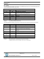
1
ECHOTRAC CVM
USER MANUAL
Version: 4.04
Odom Hydrographic Systems, Inc.
1450 Seaboard Avenue
Baton Rouge, Louisiana
USA
70810-6261
Telephone: (225) 769-3051
Fax: (225) 766-5122
[email protected]
http://www.odomhydrographic.com
Number of pages: 48
Date: May 27, 2008
Echotrac CVM
User Manual
Revision History
Version
0.1
1.24 b
3.0
3.01
3.08
Date
07-01-2003
07-19-2003
11-09-2004
11-23-2004
04-14-2005
Author
P. Oostenrijk
P. Oostenrijk
P. Oostenrijk
P. Oostenrijk
P. Oostenrijk
3.10
3.20
08-11-2005
01-16-2006
P. Oostenrijk
P. Oostenrijk
3.21
3.22
02-01-2006
02-28-2006
P. Oostenrijk
P. Oostenrijk
3.23
05-22-2006
P. Oostenrijk
3.24
07-17-2006
S. Apsey
3.25
08-03-2006
P. Oostenrijk
3.26
09-07-2006
P. Oostenrijk
3.27
09-22-2006
P. Oostenrijk
3.28
3.29
09-27-2006
05-22-2007
P. Oostenrijk
P. Oostenrijk
Remarks
Initial version – draft
Accepted Beta version
Released version: updated for CV3 and parameter list.
Minor changes to Load Settings
Updated manual for firmware version 3.08
Added section on how to request parameter settings through
the serial port.
Added Standby-bit feature
Added UDP port, 8/16 Bit data and Operation time
Added support for Asian Language pack
Corrected dimensions: 17”x17”x3.5”
Added DESO_DDV outputstring
Removed Echoalarm for Echotrac CV
Removed TVGgainref and Trackinggate for Echotracs.
Test version for new Deso command handling.
New optimized Deso command handling routines.
Re-enabled TVGgainref and Trackinggate in Echotrac Control
program. Improved annotation handling.
Improved Echotrac Control program network detection
interface. Low Frequency pulse width increased to 256.
Corrected auto-scaling when draft and index are used.
Added support for Echotrac CVM.
Added section in the manual to show how to connect the
transducers for different configurations of Echotrac CV/CV3
Added external trigger.
Fixed: Stopping the synchronization process disabled
communication with Echotrac.
Added compatibility check and warning for Echotrac Control
Program version and Echotrac firmware version.
If during synchronization a parameter is missing, the parameter
name is now displayed.
Improved version control in firmware and diagnostic window.
Added Echotrac and Subbottom mode.
Added Datacheck for GPS and Heave.
Depth values are red in case of depth alarm.
Added transparency feature on depth monitor window.
Added support for CV100.
Added Power & Gain control to Depth Monitor window.
Fixed problem with Scale width at 15 feet.
Fixed problem with communication when switching to
subbottom mode.
Echotrac CVM Maximum and Default values changed.
When depth is 0 it is in red. When channel is turned off, “OFF”
would also be in red instead of black.
Display versions according to boards in Echotrac.
Removed “Accept automated changes” feature.
Added description for Missed Returns on Setup tab.
Minor change in Grey Shades description. Updated COM port’s
baudrate options to include 38400.
Removed chapter Overview Parameters and Settings. This is
now refers to the Technical Specification Ethernet Interface
Page 2 of 2
Odom Hydrographic Systems, Inc.
May 27, 2008
Echotrac CVM
User Manual
4.00
02-19-2008
P. Oostenrijk
4.01
4.02
4.03
02-25-2008
03-13-2008
05-23-2008
P. Oostenrijk
P. Oostenrijk
P. Oostenrijk
4.04
05-27-2008
P. Oostenrijk
document.
Updated Odom Title and Logo on cover page.
Updated Header and Footer according to new template.
Updated the introduction section and listed major changes.
Inserted screen capture of new dialog for selecting a sounders
on the network.
Added Channel signal types and Bandwidth on System Tab.
Update the NMEA serial output string formats.
Updated uploading firmware and upgrading DSP firmware.
Updated document version to match software/firmware version.
Minor firmware change with model names.
Updated Scale change functionality.
Updated CVM channel handling as 1 and 2 instead of 1 and 3.
DBT outputstring changed on pages 54 and 55. Two channels
enabled = ‘B’ instead of ‘I’ or ‘M’. If the first depth has an error,
‘e’ is used. If the second depth has an error, ‘o’ is used unless
also the first depth as an error.
Removed references to Echotrac Control Program. This
application has been replaced by Odom eChart.
© ODOM HYDROGRAPHIC SYSTEMS, INC. 2008
All rights are reserved. Reproduction in whole or in part is prohibited without the prior written consent of the copyright owner.
The information presented in this document does not form part of any quotation or contract, is believed to be
accurate and reliable and may be subject to change without notice. The publisher will not accept any liability for
any consequence of its use. Publication thereof does not convey nor imply any license under patent- or other
industrial or intellectual property rights.
Page 3 of 3
Odom Hydrographic Systems, Inc.
May 27, 2008
Echotrac CVM
User Manual
CONTENTS
1
Introduction...................................................................................................................................................... 6
1.1
1.2
1.3
1.4
2
Purpose ....................................................................................................................................................... 7
Scope .......................................................................................................................................................... 7
Glossary ...................................................................................................................................................... 7
References .................................................................................................................................................. 7
Product description......................................................................................................................................... 8
2.1
Specifications .............................................................................................................................................. 8
2.2
Overview ..................................................................................................................................................... 9
2.3
Cabling ........................................................................................................................................................ 9
2.4
Power connector ......................................................................................................................................... 9
2.5
Choice of operating frequencies ............................................................................................................... 11
2.6
Fuses......................................................................................................................................................... 11
2.7
Signal connector TX1................................................................................................................................ 11
2.8
Serial Ports................................................................................................................................................ 12
2.9
GPS IN / OUT (for the optional internal GPS only) ................................................................................... 12
2.10
GPS antenna ......................................................................................................................................... 12
2.11
LAN........................................................................................................................................................ 12
2.12
AUX ....................................................................................................................................................... 12
2.13
EXT. REC (CV2 / CV3).......................................................................................................................... 12
2.14
Power switch ......................................................................................................................................... 12
2.14.1
Power-OFF..................................................................................................................................... 12
2.14.2
Power-ON....................................................................................................................................... 12
2.14.3
STANDBY ...................................................................................................................................... 13
2.15
Power indicator...................................................................................................................................... 13
2.16
Ethernet indicators................................................................................................................................. 13
2.17
Transmit indicators ................................................................................................................................ 13
3
Installation...................................................................................................................................................... 14
3.1
Software installation .................................................................................................................................. 14
3.2
Setting up the equipment .......................................................................................................................... 14
3.3
Powering up the equipment ...................................................................................................................... 15
3.4
Configuration and Connection of Echotrac CV and Transducers ............................................................. 16
3.5
Transducer installation .............................................................................................................................. 16
3.5.1
“THROUGH HULL” transducer installation ........................................................................................ 16
3.5.2
"SEA CHEST" transducer installation................................................................................................ 18
3.5.3
"OVER-THE-SIDE" transducer installation ........................................................................................ 19
4
Operational procedures ................................................................................................................................ 20
4.1
Things to consider when calibrating.......................................................................................................... 20
4.2
How to calibrate the Echotrac CV ............................................................................................................. 20
4.3
How to perform a bar check ...................................................................................................................... 22
4.4
Shallow Water Operation .......................................................................................................................... 23
4.5
Deep Water Operation .............................................................................................................................. 23
4.6
Using the optional built-in Starlink Invicta DGPS ...................................................................................... 24
4.6.1
Introduction ........................................................................................................................................ 24
5
Troubleshooting ............................................................................................................................................ 25
5.1
5.2
5.3
The Echotrac CV does not seem to be working........................................................................................ 25
The Echotrac CV power LED is off ........................................................................................................... 25
The Echotrac CV power LED is flickering ................................................................................................. 25
Page 4 of 4
Odom Hydrographic Systems, Inc.
May 27, 2008
Echotrac CVM
User Manual
5.4
5.5
6
What are the COM-port settings ............................................................................................................... 25
Known problems with Transducer............................................................................................................. 25
Technical specifications ............................................................................................................................... 27
6.1
Computer communications ....................................................................................................................... 27
6.2
Overview Serial Output string formats ...................................................................................................... 28
6.3
Serial output strings .................................................................................................................................. 30
6.3.1
Echotrac SBT..................................................................................................................................... 30
6.3.2
Echotrac DBT..................................................................................................................................... 31
6.3.3
Heave................................................................................................................................................. 33
6.3.4
DESO25 ............................................................................................................................................. 34
6.3.5
DESO DDV ........................................................................................................................................ 34
6.3.6
DESO COMMANDS .......................................................................................................................... 35
6.3.7
NMEA DBS ........................................................................................................................................ 35
6.4
Serial Data input / Chart annotation.......................................................................................................... 36
6.5
Serial heave input ..................................................................................................................................... 37
6.6
External Serial Control of Echotrac Parameters ....................................................................................... 38
7
Overview parameters and settings.............................................................................................................. 40
7.1
8
Uploading Firmware ...................................................................................................................................... 41
8.1
8.2
9
External Ethernet Control of Echotrac Parameters................................................................................... 40
Upgrading Motorola Processor Firmware ................................................................................................. 41
Upgrading DSP Firmware ......................................................................................................................... 42
Echotrac CV Cable Connections.................................................................................................................. 43
9.1
9.2
9.3
9.4
9.5
9.6
9.7
9.8
9.9
9.10
Serial 1 ...................................................................................................................................................... 43
Serial 2 ...................................................................................................................................................... 43
GPS In....................................................................................................................................................... 43
GPS Out .................................................................................................................................................... 43
LAN ........................................................................................................................................................... 43
Aux ............................................................................................................................................................ 44
TX1............................................................................................................................................................ 44
DC ............................................................................................................................................................. 44
AC ............................................................................................................................................................. 44
Serial Cable Connections for Echotrac with Built in GPS ..................................................................... 45
Appendix A. CABLE CONNECTIONS: ................................................................................................................. 46
Appendix B. Quick Start Operating Procedures ................................................................................................ 47
Page 5 of 5
Odom Hydrographic Systems, Inc.
May 27, 2008
Echotrac CVM
User Manual
1 INTRODUCTION
There are four Echotrac CV units named Echotrac CV100, Echotrac CV200, Echotrac CV300 and Echotrac CVM
(Mobile). This document covers the Echotrac CVM and will refer to this unit as “Echotrac CV”. This Echotrac CV
supports two channels.
The Echotrac CV is a hydrographic echo sounder design incorporating the cutting-edge technology, features and
reliability of the Echotrac MKIII, plus the ease and flexibility of operation of a networked Windows® interface.
The Echotrac CV transceiver units are supplied in a compact rack mount package that is ideally suited to many
shipboard installations. The Echotrac CV supports Chart-functionality in one optional format, a laptop with a full
size color LCD as an “electronic chart”. A different option, that of operating the unit and collecting data on a
networked PC, is also possible. The optional color LCD laptop offers internal data storage (in .XTF format) and
playback of the analog return signal digitized to full 16-bit resolution. This Echotrac CV can only contain a Dual
channel board. All channels feature a robust design and frequency agility enabling the operator to precisely
match the transceiver to almost any existing transducer. Operator selectable TVG curves (10 Log, 20 Log, 30
Log, 40 Log, and Off) serve to optimise the Echotrac for both shallow and deepwater bottom detection tasks and
for Sonar imaging. The Echotrac CV features unsurpassed interfacing flexibility, offering 2 serial ports that can be
configured to interface with computers and motion reference units. The Echotrac CV also has an Ethernet port
that outputs the 16 bit samples of the acoustic data for further processing or visualization. The Echotrac CV also
supports a number of output formats that are compatible with most common Echo Sounder strings.
Figure 1: Echotrac CVM
To learn about the features of the Echotrac CV, this document is structured as a step by step manual; covering
the Echotrac CV as a product, how to install the software and the equipment, how to use all the different control
settings, how to perform certain procedures, how cables are wired to their connectors and troubleshooting.
Some of the major changes as of version 4.00 are:
-
-
Replacement of the Echotrac Control Program with Odom eChart, a graphical data acquisition program.
Because the Echotrac Control Program 4.00 will become obsolete, it does not support some of the major
changes such as faster synchronization and adapting to the sounder’s hardware configuration.
Faster synchronization due to improved communication protocol.
Automatic detection of sounder(s) on the network and adapting to the sounder’s hardware configuration.
Page 6 of 6
Odom Hydrographic Systems, Inc.
May 27, 2008
Echotrac CVM
User Manual
1.1
Purpose
The purpose of this document is to explain the features and operation of the Echotrac CV.
1.2
Scope
The content of this document is focused on the end-user.
1.3
Glossary
DBS
DBT
DGPS
DSP
ETCV
NMEA
SBT
TNC
TVG
VDC
Depth Below Surface
Dual Bottom Tracking
Differential Global Positioning System
Digital Signal Processor
Echotrac CV
National Marine Electronics Association
Single Bottom Tracking
Threaded Nut Connector
Time Varied Gain
Volts Direct Current
1.4
References
[1]
Title:
Author(s):
Report no:
Version:
Date:
Windows Flash Utility: OdomFlash.exe
Patrick Oostenrijk
N/A
2.2
2007-02-27
[2]
Title:
Author(s):
Report no:
Version:
Date:
Using Echotrac Ethernet Driver with Hypack
Stephen Apsey
N/A
1.0
2006-07-17
[3]
Title:
Author(s):
Report no:
Version:
Date:
Technical Specification Ethernet Interface
Patrick Oostenrijk
N/A
1.8
2008-05-28
Page 7 of 7
Odom Hydrographic Systems, Inc.
May 27, 2008
Echotrac CVM
User Manual
2 PRODUCT DESCRIPTION
2.1
Specifications
Frequency
•
High Band: 100 kHz-1 MHz
•
Low Band: 10 kHz-50 kHz
Output Power
•
High: 100 kHz – 500 W RMS max
200 kHz – 400 W RMS max, 750
kHz – 200 W RMS max
•
Low: 12 kHz – 1kW RMS max, 50
kHz – 750 W RMS max
•
Very Low: 3kHz – 4kW (transducer
impedance dependant)
Input Power
•
110 or 220 V AC or 24 VDC 50
watts
Resolution
•
0.01m / 0.1 ft.
Accuracy
•
0.01m / 0.10 ft. +/- 0.1% of depth @
200 kHz
•
0.10m / 0.30 ft. +/- 0.1% of depth @
33 kHz
Depth Range
•
0.2 – 200m / 0.5 – 600 ft. @ 200
kHz
•
0.5 – 1500m / 1.5 – 4500 ft. @ 33
kHz
Chart Scales
•
5,10,20,40,80,100,200,400,800,
1600 m
•
15,30,60,120,240,300,600,1200,
2400,4800 ft.
Phasing
•
Automatic scale change, 10%,20%,
30% overlap or Manual
Sound Velocity
•
1370 – 1700 m/s
•
Resolution 1 m/s
Transducer Draft Setting
•
0 – 15m (0 – 50 ft.)
Depth Display
•
On control PC.
Clock
•
Internal battery backed time,
elapsed time, and date clock
Annotation
•
Internal – date, time, GPS position
•
External – from RS232 port or
Ethernet.
Interfaces
•
2 x RS232 serial ports, baud rate
selectable 4800-19200.
•
Inputs from external computer,
motion sensor, sound velocity.
•
Outputs to external computer
•
Ethernet interface
•
Heave – TSS1 and sounder
sentence
Blanking
•
0 to full scale
Software
•
Echotrac Control supplied
ChartView display and logging
•
software
Help
The function of each parameter and it’s
minimum and maximum values can be
displayed.
Environmental Operating Conditions
•
0°– 50° C, 5 – 90% relative
humidity, Non-condensing
Dimensions
•
53 cm (20.75”) H x 44cm (17.25”)
W x 21.5cm (8.5”) D
Weight
•
13.8 kg (31 lbs.)
Options
•
One or two acoustic channel.
•
Side Scan Transducer – single or
dual channel side looking 200 kHz
for 340kHz for search and
reconnaissance
•
Built-in DGPS
Page 8 of 8
Odom Hydrographic Systems, Inc.
May 27, 2008
Echotrac CVM
User Manual
2.2
Overview
DC
DC
FUSE FUSE
F1
F2
115/
220
VAC
24 VDC
TX 1
LAN
AUX
GPS
ANT
PC Power
Serial 1
GPS OUT *
GPS IN *
Serial 2
On the panel of the Echotrac CV are all the connectors for serial communication interfacing, GPS data, Ethernet
communication, Transducer signals and power. See below, in Figure 2 for an overview of all the connectors. Each
item will be explained in more detail in the following chapters. The panel has LED indicators for Ethernet
communication, Transceiver board operation and power.
Figure 2: Overview of Echotrac CV
* Important Note: The GPS IN and GPS OUT connectors are only used when there is an internal GPS system
built into the Echotrac CV. These two connectors are connected directly to the internal GPS ports A and B to
provide external communication with the GPS. The connector labeled GPS IN is used to change the internal GPS
settings such as Baudrate etc. The connector labeled GPS OUT is used by the GPS to output the GPS
positioning data.
The Echotrac CV is built into a tough, splash proof plastic case for mobility.It is highly recommended that the unit
be secured with external 'tie-downs' for rough seas or heavy swells.
2.3
Cabling
All cabling is via the connectors located on the recessed panel on top of the unit. A view of the connector
arrangement is shown in Figure 2. Cable details are given in Appendix A. Care should be taken to route cables
using horizontal and vertical runs wherever possible. Avoid paths that run adjacent to transmitter feeder cables or
close to heat radiating elements such as steam pipes. For permanent installations, cables should be clamped at
regular intervals (1m) along their complete lengths.
2.4
Power connector
The Echotrac CV can be powered by either AC or DC power sources. Switch over between sources is automatic.
DC operation requires an input voltage between 18 and 29 VDC (nominal 24 VDC). Average power consumption
is approximately 25-30 watts. Frequently, power is derived from two 12 V lead-acid batteries connected in series.
These batteries (24V configuration), fully charged, and in good condition, can normally power a unit for a full day
without re-charging.
If using an AC source, the unit’s internal switcher accommodates either 230 or 110 VAC (50/60Hz) operation
without operator intervention. Regardless of the input source (AC or DC), the input power should be well
regulated and monitored closely for voltage transients, spikes, etc. Regulated DC supplies should be able to
Page 9 of 9
Odom Hydrographic Systems, Inc.
May 27, 2008
Echotrac CVM
User Manual
source a short duration in-rush current spike of approximately 6 amps and an average current load of 3 amps. In
the case of "charger" type (unregulated) supplies, the output should be "floated" across a battery load and not
connected solely to the echo sounder’s DC input. Details of the power cable are given in Appendix A. Should the
DC input voltage polarity be applied in reverse, an audible alarm within the unit will sound regardless of the
POWER switch setting. In the event that the input voltage drops below the minimum threshold the unit will
automatically shut down.
Page 10 of 10
Odom Hydrographic Systems, Inc.
May 27, 2008
Echotrac CVM
User Manual
Setting up two batteries in series (24 Volts DC system)
DC Power cable
(-)
(+)
(-)
Battery 1
12 Volts
(+)
Battery 2
12 Volts
Jumper
Using a jumper simply connect the positive post of battery 1 to the negative post on battery 2. Connect the
negative lead from the power cable to the negative post on battery 1 and the positive lead to the positive post on
battery 2. Always check the voltage with a voltage or multi-meter before connecting the DC power cable to any
equipment. Make sure that all the connecting equipment is also turned off before applying the power cables.
Otherwise the transients of such a ‘jump-start’ could damage the equipment.
2.5
Choice of operating frequencies
The Echotrac CV can be configured to use either a combination of a Dual channel board with a High and a Low
frequency channel, respectively 100 kHz – 1 MHz and 10 kHz – 50 kHz, or a Dual channel board with two High
frequency channels.
Standard transducers are generally available from stock that support the frequency ranges listed on the product
description page (See 2.1 Specifications).
2.6
Fuses
For DC operation, both the positive and return lines are protected by fast blow standard glass tube (5-Amp/250
Volts) fuses and are located behind the waterproof twist-lock caps. The two externally accessed fuses are
mounted on the rear connector panel. The negative fuse protects the unit from damage resulting from contact with
external peripherals that do not share a common return path potential. A 5-amp fuse is included in the AC input
connector as well.
2.7
Signal connector TX1
Use signal connector TX1 when you have a single High or Dual Frequency transducer. The signal from the
transducer is passed to the Echotrac CV via a standard Odom transducer cable with a twist-lock connector. The
twist-lock connector is attached to the Echotrac CV where a connector is labeled “TX1”.
See chapter 9: Echotrac CV Cable Connections for cable configurations.
Page 11 of 11
Odom Hydrographic Systems, Inc.
May 27, 2008
Echotrac CVM
User Manual
2.8
Serial Ports
Serial 1
The Echotrac CV uses Serial port 1 to output depth data. Using a special Flash Utility program, the port is also
used to upgrade the software in the Echotrac CV. Another use of the port is to send commands to the Echotrac
CV or request certain parameter settings.
Serial 2
Serial port 2 is used to receive motion sensor data in TSS1 format (heave). This port enables the Echotrac CV to
accept data from a motion compensator to apply corrections for the vertical movement caused by swells. The
Echotrac CV will only correct the depth for Heave. No corrections are done for Roll and Pitch.
2.9
GPS IN / OUT (for the optional internal GPS only)
The DB9 (RS232) connector labelled “GPS IN” can used to configure the optional internal GPS or enter RTCM
corrections to the internal GPS. The DB9 (RS232) connector labeled “GPS OUT” is used to output the GPS data
from the optional internal GPS system. On the physical GPS unit these ports would be labelled as ports A and B.
The internal GPS system is an optional feature and does not come standard in the Echotrac CV.
2.10 GPS antenna
The GPS antenna for the optional internal GPS can be attached to the TNC connector labeled “GPS antenna”.
2.11 LAN
The LAN port is used by the Echotrac CV to send and receive data on the network. The Echotrac CV can be
connected directly to a Hub or a Switch using a regular UTP CAT-5 ethernet cable. A regular cable is also known
as a ‘straight’ UTP cable. When the Echotrac is connected directly to a computer, a so-called ‘cross-over’ UTP
cable must be used. When a computer is directly connected to the Echotrac CV using a crossover cable, the
operating system on the computer may take 2-3 minutes before the computer has accepted a valid IP address. To
prevent this delay, you can assign the computer a static IP address or use a Hub/Switch.
2.12 AUX
The auxiliary port is used for acquiring the analog signal from the Echotrac CV.
2.13 EXT. REC (CV2 / CV3)
The External Recorder port is used to connect the optional external printer. This is only available on the Echotrac
CV2 and CV3.
2.14 Power switch
The power switch in the ON position will power-up the internal circuitry. In the OFF position it will power-down the
internal circuitry.
2.14.1 Power-OFF
The main power switching circuitry is open in this position. Please note that the Echotrac CV switches
automatically between AC and DC operation when an appropriate source of power is applied to the unit. Should
both AC and 24VDC be applied to the unit at the same time, then the Echotrac will automatically favour the
24VDC supply.
2.14.2 Power-ON
On "power-up", the unit performs a Self-test to check system memory and also tests the Non-volatile RAM battery
voltage. If there was a problem with the Non-volatile RAM, the factory defaults will be loaded. The unit then enters
the sounding mode and begins data acquisition.
Page 12 of 12
Odom Hydrographic Systems, Inc.
May 27, 2008
Echotrac CVM
User Manual
2.14.3 STANDBY
The main power circuitry is energized, drawing current from the mains and providing regulated DC voltages to all
internal modules.
The unit is no longer in the sounding mode when it is in the standby position. However, the Parameter Entry
System is enabled.
2.15 Power indicator
When the Echotrac CV is turned on, a green LED will be on to indicate that the internal systems have powered up
successfully. The green LED is located next to the power switch.
2.16 Ethernet indicators
The TX indicator on the Echotrac CV indicates whether or not the data is transmitted on the Ethernet port. The
frequency at which the TX indicator flickers also indicates whether the Echotrac CV is outputting data at a slow or
fast pace.
The Link indicator on the Echotrac CV indicates that it recognizes the presence of a network. If the receiving end
of the ethernet cable is connected to a computer or a hub/switch that is not powered on, the link light will not be
on.
2.17 Transmit indicators
The Channel indicators on the Echotrac CV indicate whether that particular Transducer is firing or not. The
frequency at which the Channel indicator flickers also indicates whether the Transducer is firing at a slow or fast
pace. The other Channel indicators work in the same way.
Page 13 of 13
Odom Hydrographic Systems, Inc.
May 27, 2008
Echotrac CVM
User Manual
3 INSTALLATION
This section contains the information necessary to install the Echotrac Control Software, power-up and connect
the Echotrac CV. The installation procedure consists of a number of steps. Each step corresponds to a specific
chapter. It is recommended that these steps (chapter 3.1, 3.2 and 3.3) for the installation procedure be followed in
this order. See also the quick start procedure in Appendix B.
3.1
Software installation
The minimum requirements for a personal computer to install and run only the Echotrac Control software are:
• Windows 98
• Pentium-I, running at 200 MHz
• 32 Mb of internal memory
• 10 Mb of free space on the harddrive
• One COM-port
The Echotrac control program is fully tested on the following Operating Systems:
• Windows 98
• Windows 2000
• Windows XP
• Windows NT
Note: Windows ME is not supported.
Note: A minimum of two COM-ports are needed to run: one port to receive serial data from the Echotrac and
communicate with the Echotrac, and one port to receive GPS. This is an example of a situation when ethernet
cannot be used.
The software that is shipped with the unit can be installed on the personal computer by executing the program
called SETUP.EXE. This program will install the Echotrac Control software in the Program Files directory. During
the setup process it is possible that Windows will ask if you wish to keep certain files on the computer that are
older or newer than the ones being installed. By default it is advised to keep the files that are currently on the
computer to avoid any conflicts or problems with other programs. If during the setup process, the setup program
cannot find the files on your computer that it needs to install the Echotrac CV, the missing file(s) will be copied
onto the hard drive.
3.2
Setting up the equipment
The Echotrac CV is a lightweight unit designed for portability. An interconnection diagram is shown in Figure 3.
Care should be taken to route cables using horizontal and vertical runs wherever possible. Avoid paths that run
adjacent to transmitter feeder cables or close to heat radiating elements such as steam pipes. For permanent
installations, cables should be clamped at regular intervals (3 feet or 1 meter) along their complete lengths.
The Echotrac CV requires either an input voltage between: +18 and +29 VDC (standard) or between 110 and 220
VAC. The unit consumes less than 30 watts of power in normal operation. Power is frequently derived from one
or two 12 V lead-acid batteries. Two batteries (24V configuration), fully charged, and in good condition, can
normally power a unit for a full day without re-charging. Details of the power cable are given in the chapter 2.4
Power connector and the Appendix .
All cables are attached to the connectors located in the recessed area at the left rear of the unit (See Figure 2 in
chapter 2.2). Connections are made through multi-pin “MS” style connectors, between the Echotrac CV, its power
source, the transducer and all computer or peripheral devices.
The following Interconnection block diagram shows everything that can be connected to the Echotrac CV. All
these peripherals are not required to use the basic functionality of the Echotrac CV.
Page 14 of 14
Odom Hydrographic Systems, Inc.
May 27, 2008
Echotrac CVM
User Manual
i
Motion Sensor (COM2)
ECHOTRAC CV
f
GPS Antenna
a/d
g
e
Optional
Internal GPS
c
Power
control (COM1)
GPS OUT
GPS IN
Computer
b
Transducer(s)
Figure 3: Interconnection block diagram
Before connecting any of the cables, make sure that the computer, the Echotrac CV and other peripherals are
turned off. The list below is a sequence of steps for connecting the Echotrac CV with the computer and GPS. If
any problems arise, see the Troubleshooting section.
a) Connect the RS232 cable between the computer and the DB9 connector labeled “Serial 1”, if you need to
collect depth data through the serial port or need to send command to the Echotrac CV.
b) Connect the cable from the Transducer to the connector on the Echotrac CV labeled “TX1”.
c) Connect the power cable for the Echotrac CV to the connector labeled “POWER”.
d) Connect the UTP ethernet cable to the LAN connector if you want to collect data across a network.
If the optional internal GPS is used, then:
e) Configure the optional internal GPS, using special software, through the connector labeled “GPS IN”.
f) Connect the GPS antenna cable to the connector labeled “GPS antenna”.
g) Connect the RS232 cable between the connector labeled “GPS OUT” with a COM-port on the computer.
If an external peripherals are used, then:
h) Connect the RS232 cable between the motion sensor and the connector labeled “Serial 2”.
3.3
Powering up the equipment
The following sequence must be followed when powering up the equipment:
1. Turn on the personal computer.
2. Turn on the Echotrac CV. After turning the Power Switch from the OFF position to ON, confirm that the power
LED, Ethernet Link LED come on. After a few seconds, the Ethernet TX/RX LED and one or both of the
Transmit High / Low LEDs should start blinking.
3. Start the Echotrac CV Window Application program.
4. Turn on optional peripherals such as GPS or motion sensor.
5. Depending on water depth and bottom type, set the Tx Power to mid-range (position 6) in the Echotrac control
program.
6. Set the RxGAIN to about halfway on the maximum scale.
7. Adjust RxGAIN and TxPOWER to get a clear strong record with few alarms on the displayed depth.
Note: The Echotrac CV should always be turned on before running the Echotrac control program.
Note: Should you feel that a return to the sounder’s default parameter values is called for, then select the Default
Reset option in the Echotrac CV Window Application program.
Page 15 of 15
Odom Hydrographic Systems, Inc.
May 27, 2008
Echotrac CVM
User Manual
3.4
Configuration and Connection of Echotrac CV and Transducers
Use the Model Number column to identify which Echotrac CV you have by looking at the Serial number sticker on the
back of your Echotrac CV. Use the table to determine how to connect your transducers. When configuring the Echotrac
CV in the control program make sure the correct frequency is entered for the appropriate transducer by looking at which
channel in the control program is controlling each transducer. TX1 and TX2 refer to the transducer connectors on the
back of the Echotrac CV
Model
Number
ETCVM-A
Echotrac
Model
CVM
Channel 1
Channel 2
High
Frequency
Low
Frequency
ETCVM-B
CVM
High
Frequency
High
Frequency
ETCVM-C
CVM
ETCVM-D
CVM
High
Frequency
Low
Frequency
3.5
Channel 3
Notes
If using separate transducers use
adaptor PN# 2311-0011-0000 to
connect each transducer.
If using separate transducer use
adaptor PN# # 2311-0007-0000 to
connect the each transducer.
Transducer installation
Proper mounting of the transducer is a crucial part of the installation of any "survey" echo sounder. An improperly
mounted transducer will result in poor system operation and unacceptable data quality.
Important: See also chapter 5.5 Known problems with Transducer.
In the case of temporary installations, the transducer is often mounted over-the-side. In permanent installations
and "pay surveys," hull mounts are generally preferred and often required. In either case, the transducer should
be mounted as far below the waterline as possible. In cases where "over the side" mounts are exposed to wave
action, ensure that the transducer is mounted far enough below the surface so that it remains well submerged
during vessel roll motions.
A preferred mounting location is near the keel of the vessel, in an area where the planing attitude of the hull and
the pitch and roll angles of the vessel have the least effect at operating speed. The transducer should be
mounted far enough aft of the bow so that bubbles generated by the bow wave will not pass over the face of the
unit. Transducers should be located away from sources of turbulence and cavitation bubbles such as propellers,
bow thrusters and hull protrusions. Consideration should also be given to sources of mechanical noise generated
within the vessel (engines, propellers, pumps, generators, etc.). In some severe cases of mechanically coupled
noise, vibration-isolating mounts may be required to mechanically decouple the transducer from the hull.
Transducer mounting can be accomplished in many different ways. The following three chapters show common
configurations.
3.5.1
“THROUGH HULL” transducer installation
The top side of the transducer is accessible from inside the vessel while the transducer face is directly exposed to
the water. Care should be taken to protect the transducer from damage and turbulence by installing a fairing with
a sloping forward edge ahead of the unit. The fairing has the dual effect of both minimizing possible strike
damage and smoothing the flow of water over the face of the transducer.
Page 16 of 16
Odom Hydrographic Systems, Inc.
May 27, 2008
Echotrac CVM
User Manual
Figure 4: Transducer mounted through the hull
Page 17 of 17
Odom Hydrographic Systems, Inc.
May 27, 2008
Echotrac CVM
User Manual
3.5.2
"SEA CHEST" transducer installation
In a "sea chest" mount, a fluid-filled enclosure large enough to contain the entire transducer is attached to the
outer hull of the vessel. The outer hull is removed within the area of the chest and replaced with an acoustically
clear "window" which is mounted flush with the hull surrounding the chest. Depending on construction, the
material selected for the acoustic window, and the draft of the vessel, access can often be gained to the
transducer from inside the hull without putting the vessel in dry-dock. In most installations, a water-filled
standpipe is incorporated into the "sea chest" design in order to provide hydrostatic pressure equalization.
Transducer cables generally leave these assemblies through stuffing tubes, which maintain the watertight integrity
of the chest.
Page 18 of 18
Odom Hydrographic Systems, Inc.
May 27, 2008
Echotrac CVM
User Manual
3.5.3
"OVER-THE-SIDE" transducer installation
A mount of this type is frequently constructed from a length of pipe. This fixture should be sized to position the
transducer well below the waterline and the pipe then fixed to a sturdy support on the vessel. Lines generally are
attached at the transducer pipe and tied off fore and aft in order to maintain a stable, horizontal transducer
attitude. Care should be taken to assure adequate protection for the transducer cable, particularly at the point
where the cable leaves the transducer body.
In all of the above installations, particular care should be taken to assure that the transducer radiating face
remains as parallel to the water surface as much as possible while the vessel is moving.
Page 19 of 19
Odom Hydrographic Systems, Inc.
May 27, 2008
Echotrac CVM
User Manual
4 OPERATIONAL PROCEDURES
The following sequences are typical operating procedures for the Echotrac. The procedures may vary according
to survey requirements and are intended only as a guide. It is assumed that the operator is familiar with the
various controls and their associated functions as detailed in the preceding sections of this manual.
4.1
Things to consider when calibrating
1.
2.
3.
4.
5.
8.
9.
10.
11.
12.
13.
14.
4.2
Calibrate daily in an area that is calm; avoid any “rocking” of the vessel.
Never use rope or material that might stretch on your calibration bar.
Calibration of the CV can be for both frequencies at once.
Perform calibration using the shallowest and deepest depths from your area.
If you do not have a velocimeter to compute the speed of sound, start with the default speed of the unit.
(5000 feet or 1500 meters per second or the speed from the previous day).The echo sounder is calibrated
using draft, index and speed of soundMeasure the draft using a survey tape measure
Apply index for the shallow calibration.
Apply speed of sound changes for the deeper depths.
If the water depth is less than 20 feet (6 meters). As long as your unit is in the average speed of sound
range, use only the measured draft and index for calibration. In other words, the speed of sound will have
little effect.
If the water depth ranges from .5 to 60 feet (18 meters), build a calibration bar that can reach the deepest
part of the survey.
For depths that exceed 60 feet use a bar that can reach as deep as possible. In areas such as these we
recommend that you use a velocimeter as a check.
Always document and save your work.
Selecting another tab in the Echotrac Control program exits the calibration functionality.
How to calibrate the Echotrac CV
The principle of echo sounding is based on measuring the time of arrival of an acoustic return (echo) referenced
to the time of transmission. The time required for sound to travel from a source (the transducer) to a destination
point (the seafloor or bottom) and back can be measured and multiplied by the velocity of sound in water. This
provides us with the distance that the pulse has traveled in the water column. Because the transmitted pulse
traveled from the transducer to the bottom and back again, the distance must be halved to obtain the true water
depth. Furthermore, other factors need to be included into the formula. If the transducer is submersed under
water, the distance from the water surface to the transducer, in other words the draft value, must also be
accounted for. If the calculated water depth does not exactly match the physically measured water depth, the
index value is used as a correction offset. The general depth formula is shown below.
d = v x t -k +dr
2
Where:
d
v
t
k
dr
ÍÎ
d = ½ (a x t) – k + dr
- Actual depth from water surface to the bottom.
- Average velocity of sound in the water column.
- Elapsed time measured from the transducer to the bottom and back to the transducer.
- Index constant.
- Distance from the referenced water surface to the transducer (draft).
Page 20 of 20
Odom Hydrographic Systems, Inc.
May 27, 2008
Echotrac CVM
User Manual
d = ½ (a x t) – k + dr
Transducer
dr
d
a
Many users may not be familiar with the parameter “Index” or “k”, although it is likely that they have seen the
results of combining transducer draft and index constant into one draft figure. If you have noticed that the
measured draft, or the distance from the face of the transducer to the water’s surface is not the same as the draft
value entered into the sounder, then you have seen the result of lumping both together. This phenomenon is
most evident when using dual frequency transducers where both high and low elements are in the same housing.
Often, the draft values are very different for the two frequencies if no adjustable “k” parameter is incorporated.
The difference in “k” or electronic delay between a 200 kHz element and a 24 kHz array is substantial, and is the
reason behind the difference between the two “Calculated Drafts”.
Once the “k” value is determined, it will not change until either the sounder or the transducer is changed. The
Index parameter should be adjusted to make the measured draft and the calculated draft equal.
Since the accuracy of measuring the depth depends on the value used for the velocity of sound in water (along
with the other factors shown above), it is important that a realistic value for sound velocity is used. In water,
velocity is a function of temperature, salinity and pressure. Therefore, the sound velocity in one area may vary
from the sound velocity measured in another area. This means that whichever type of echo sounder is used, it
must be calibrated in order to provide the most accurate depth data at a given location.
The most common calibration technique is the “Bar-Check” method. This method, when employed properly, has
the advantage of determining the sound velocity, draft, and index value. When this method of calibration is used,
acoustic sound waves are bounced off a suspended target that is lowered to a known depth between the
transducer and the bottom. In this situation it is desirable that the digitizer will see only the Bar (the target) and is
unable to lock on to acoustic returns from the bottom. Because the Echotrac CV employs a dynamic tracking gate
or window through which the digitizer looks for returns or echoes from the bottom, manual control for the position
and width of the gate is necessary. This will force the digitizer to only detect returns from the Bar. See section 4.3
on how to perform a bar-check.
Page 21 of 21
Odom Hydrographic Systems, Inc.
May 27, 2008
Echotrac CVM
User Manual
4.3
How to perform a bar check
This section describes an example of how to perform a bar-check.
1. Setup the equipment and start the Echotrac control program.
2. Set the Range at 60 feet. Select the bar-depth (start with a shallow depth, typically 5 feet), bar-width (typically
1 foot), Sound velocity, Draft (measured), Index (start with 0), End-of-scale and Scale width. The Echotrac
control program is now in calibration mode because the bar-depth is greater than “0”.
3. Lower the bar into the water column and place it at 5 feet below the water’s surface. The Digitizer in the
Echotrac CV will expect to see a target at that 5.00-foot depth while rejecting all other returns (including those
from the bottom).
4. Adjust the index to the correct depth.
5. Change the bar depth in the Echotrac control program.
6. Adjust the sound velocity up or down until the digitized depth matches the measured bar depth.
7. Repeat steps 3, 4, 5 and 6 to verify the calibration procedure until your reading matches the depth of the bar.
IMPORTANT:
Adjust the draft only when the bar is at the shallowest depth, because this is where the sound velocity has little
affect on the calibration.
Adjust the sound velocity only when the bar is lowered to greater depths, because this is where the sound
velocity becomes pre-dominant.
Draft + Index
Bar depth
Transducer
Bar
Bar gate width
The figure above shows that the bar is placed under the transducer and kept at a certain measured depth using
cables.
Page 22 of 22
Odom Hydrographic Systems, Inc.
May 27, 2008
Echotrac CVM
User Manual
4.4
Shallow Water Operation
Set the Transmit power to mid-range, adjust the Receive gain to approximately midrange (this applies to both
High and Low frequencies in dual mode) or Auto.
Ensure that the key parameters velocity, channel, draft, and index are correct. Amend any of these parameters as
required.
If necessary, slowly adjust the Receive gain controls until the desired quality is obtained and no digitizer alarms
are displayed. Adjustment of the Transmit power control may be called for at this point. A balance between
Receive gain and Transmit power is generally desired. In many situations AUTO power will satisfy record quality
requirements while at other times, where local bottom conditions dictate some variation of the Transmit
power/Receive gain ratio, a manual position may work best. Note that the MAX setting on any of the above
controls is seldom required.
Should the record show evidence of sporadic noise, which cannot be overcome using the Receive gain controls,
and should the digitizer lose lock due to this noise, then several alternatives are available. First, determine
whether the digitizer is attempting to lock to a false echo or to the end of the Transmit Pulse. In either of these
cases, enter a value for Blanking which is deeper than the false return. This will force the digitizer to lock to the
bottom. If the Echotrac is connected to an external computer/data logger, confirm that correct digitized depths are
being transferred.
4.5
Deep Water Operation
Please note that deep water operations require a bit more time to accomplish, due to the fact that returns from the
bottom are received so much less frequently in deep water
In the CHART menu select either the Auto or Manual scale change.
Select the low frequency channel to Bathymetry.
Set the Chart Speed to AUTO. Setting the chart to advance one dot row per sounding will improve the
appearance of the chart and eliminate the “blocky” appearance of records produced with low ping rates but high
chart speeds.
Set the RANGE value to encompass the greatest depth likely to be encountered. For example: if working in
2,000 meters of water, enter a RANGE value of at least 2,500.
LF Pulse Width should be set to a value of at least 30. Used in conjunction with the front panel control, TX
Power, the pulse width and amplitude determine how much acoustic energy is actually transmitted toward the
bottom.
Back in the CHART menu, set the Chart Width value to suit the desired resolution. Remember, at a Chart Width
of 1600, each dot represents 1 meter. If you have chosen to work in the Manual Scale Change (Scale) mode,
then set the End of Chart value to the anticipated depth of the bottom.
Turn Blanking On by entering a value. A Blanking value which is a bit shallower than the “Shoalest” depth likely
to be encountered, will help screen the digitizer from unwanted “false echoes” in the upper water column.
Begin by noting the position of the TX Power switch. In most cases of depths over 1,000 meters, the unit should
be run at a fairly high power level (6 or greater). Slowly adjust the Receive gain potentiometer to give the desired
chart quality and to allow the digitizer to lock to the bottom.
Page 23 of 23
Odom Hydrographic Systems, Inc.
May 27, 2008
Echotrac CVM
User Manual
4.6
4.6.1
Using the optional built-in Starlink Invicta DGPS
Introduction
The optional internal DGPS receiver for the Echotrac CV is intended to provide the user with a compact and
rugged hydrographic survey tool. With the addition of a data acquisition computer and appropriate software, a
complete survey system can be achieved with only two “boxes.”. This can be a great advantage in remote or
otherwise inaccessible areas where portability, quick mobilization, and ease of operation are important.
As shipped from the factory, the Starlink Invicta 210 DGPS board is configured to use the integral MSK beacon
receiver for differential corrections, and to output the GLL string on the COM-port labeled “GPS OUT”. The
standard configuration can easily be changed using the program GPSMon.exe. The setup program is provided
on disk with the unit, and can also be downloaded from Starlink’s web site at www.starlinkdgps.com. The
program runs on any PC running the Windows operating system. Set up information is exchanged through one of
the serial ports on the PC and COM-port labeled “GPS INPUT” of the Echotrac CV. Changes in the configuration
do not require the operator to physically access the board.
Page 24 of 24
Odom Hydrographic Systems, Inc.
May 27, 2008
Echotrac CVM
User Manual
5 TROUBLESHOOTING
5.1
The Echotrac CV does not seem to be working
If the Echotrac CV does not seem to be working right, follow the steps below to determine the cause.
1. Check if the power LED is on and does not flicker. If it does flicker, see section 5.3.
2. The Echotrac CVs have a Standby bit that is turned on by default. Try the Echotrac Control Program to
communicate with the Echotrac CV.
3. Check if all the cables are properly connected and intact. If cables are not properly secured, electrical
signals may not be transmitted or received.
4. Make sure you are using the correct COM-port. Windows will display an error message if the port cannot
be used or if it is already open/used by another program. Programs or devices that use COM-ports are:
Modem, Mouse, Scanners, Printers.
5. Try toggling the COM-port off and on with the Windows application software you are using.
6. Make sure the Echotrac CV is not in Standby mode.
7. A blinking TX LED means that the digitizer is firing, but the data may not be sent out on the COM-port of
the Echotrac CV. The Echotrac CV could be in Standby mode.
8. Try powering down the Echotrac CV and powering it back up again. If the Echotrac CV is turned on
before the computer, it may interfere with initializing and setting up communication channels.
5.2
The Echotrac CV power LED is off
Try powering the Echotrac CV down and back up again.
If this does not resolve the problem, contact Odom Hydrographic Systems, Inc. for assistance.
5.3
The Echotrac CV power LED is flickering
Reduce the Transmit power. It may be set too high with respect to the water depth.
5.4
What are the COM-port settings
The Echotrac CV uses the following default settings for the COM-ports:
9600 baud, 8 data bits, no parity, 1 stop bit.
The COM-port used to interface with the Echotrac CV can be selected on the Communication tab in the Echotrac
control program. See also section Error! Reference source not found..
5.5
Known problems with Transducer
Always make sure that the transducer face has been cleaned with mild soap to improve the interface between the
transducer and the water. It is sometimes possible for a thin layer of air to be trapped on the face of the
transducer. This will result in poor or no signal return from the transducer.
Page 25 of 25
Odom Hydrographic Systems, Inc.
May 27, 2008
Echotrac CVM
User Manual
TRANSDUCER FACE
Air trapped under a thin film layer on the face of the transducer.
Page 26 of 26
Odom Hydrographic Systems, Inc.
May 27, 2008
Echotrac CVM
User Manual
6 TECHNICAL SPECIFICATIONS
6.1
Computer communications
Due largely to the pervasive presence of PC based data acquisition systems aboard survey vessels, the need has
arisen for echo sounders to communicate quickly and easily in a digital format. Two of the most common
communications interface formats are RS-232C and RS-422. The COM-ports on the Echotrac CV is capable of
sending and receiving data in RS232 only. In its standard configuration, the unit sends ASCII characters at 9600
baud, (8 data bits, 1 start bit, 1 stop bit, no parity) to peripherals or data logging systems at the completion of each
sounding cycle. COM-port “Serial 1” is a bi-directional serial port with the capability of accepting input data as
well as outputting serial depth information. The following section of this chapter shows an overview of all the
output strings and their formats, followed by detailed information about the output string structures.
Page 27 of 27
Odom Hydrographic Systems, Inc.
May 27, 2008
Echotrac CVM
User Manual
6.2
Overview Serial Output string formats
COMPORT
1
2
3
4
CHANNEL
CH1
CH2
CH3
Meters
Feet
Not Heave Out
X
X
Yes
-
-
Subtract heave from depth
(Applies to CH1, CH2, CH3)
Subtract heave from depth
(Applies to CH1, CH2, CH3)
DESO25
DESODDV
NMEA
ECHOTRAC SBT
ECHOTRAC DBT
-
X
X
X
Yes
No
-
DA00001.23 m
DA00001.2 ft
X
X
X
No
Yes
-
X
X
X
Yes
Yes
-
DB00001.23 m
DA00001.23 m
DB00001.23 m
DB00001.2 ft
DA00001.2 ft
DB00001.2 ft
X
X
X
Yes
No
-
DA00001.23 m
DA00001.2 ft
X
X
X
No
Yes
-
X
X
X
Yes
Yes
-
X
X
X
X
X
-
DB00001.23 m
DA00001.23 m
DB00001.23 m
DH01.23 m
(Example: Heave)
DB00001.2 ft
DA00001.2 ft
DB00001.2 ft
-
X
X
X
X
X
-
DG01.23 m
(Example: Draft)
-
X
X
X
X
X
-
CS1234 m/s
(Example: Sound velocity)
X
X
X
Yes
No
No
$SDDBS,3.3,f,1.0,M,0.6,F*AB
$SDDBS,3.3,f,1.0,M,0.6,F*AB
X
X
X
No
Yes
No
$SDDBS,3.3,f,1.0,M,0.6,F*AB
$SDDBS,3.3,f,1.0,M,0.6,F*AB
X
X
X
No
No
Yes
$SDDBS,3.3,f,1.0,M,0.6,F*AB
$SDDBS,3.3,f,1.0,M,0.6,F*AB
X
X
X
Yes
No
No
X
X
X
No
Yes
No
_et__12345
_etE_0
_ET__12345
_ETE_0
X
X
X
No
No
Yes
_et__12345
_etE_0
_ET__12345
_ETE_0
Normal
Error
Normal
Error
X
X
X
Yes
No
No
_et_H_11111
_etEH_0
_ET_H_11111
_ETEH_0
X
X
X
No
Yes
No
_et_L_22222
_etOL_0
_ET_L_22222
_ETOL_0
X
X
X
No
No
Yes
-
-
-
-
X
X
X
Yes
Yes
No
_et_B_11111 22222
_etEB_0_22222
_etOB_11111_0
_etDB_0_0
_ET_B_11111 22222
_ETEB_0_22222
_ETOB_11111_0
_ETDB_0_0
X
X
X
Yes
No
Yes
_et_B_11111 33333
X
X
X
No
Yes
Yes
_et_B_22222 33333
X
X
X
Yes
Yes
Yes
_et_C_11111 22222
33333
HEAVE OUT
Normal
Error
Normal
Error
_et__12345
_etE_0
_ET__12345
_ETE_0
_etEB_0_33333
_etOB_11111_0
_etEB_0_22222
_etOB_33333_0
_etEC_0_22222_x
_etOC_11111_0_x
_etFC_11111_0_0
_etGC_0_0_0
_ET_B_11111 33333
_ET_B_22222 33333
_ET_C_11111 22222
33333
_ETEI_0_33333
_ETOI_11111_0
_ETEM_0_22222
_ETOM_33333_0
_ETEC_0_22222_x
_ETOC_11111_0_x
_ETFC_11111_0_0
_ETGC_0_0_0
Append heave value to output string
Priority of channels:
Channel 1 has the highest priority, next Channel 2 and then Channel 3 has the lowest priority.
Therefore, if the depth for all three channels are being output, and all three have errors, then Channel 1 has the highest priority
and its error letter will be shown in the output. Not either of the other two channels because they have a lower priority.
Page 28 of 28
Odom Hydrographic Systems, Inc.
May 27, 2008
Echotrac CVM
User Manual
Channel and Error overview (for Echotrac DBT only):
Channels in use
CH1
CH2
Yes
Yes
Yes
Yes
Letter
CH3
-
H
B
L
Channel with depth Error
CH1
CH2
9 (e)
9 (e)
9 (o)
9 (e)
Letter
CH3
-
E
D (all)
E
Yes
-
Yes
Yes
Yes
B
B
9 (e)
-
9 (e)
9 (o)
9 (o)
E
E
Yes
Yes
Yes
C
9 (e)
9 (o)
9 (f)
G (all)
If multiple channels are in use and not all the channels have an error, then priority of the channels determines which letter is
displayed to indicate the Error. If all channels are used and all have an Error, a unique letter is used to identify that situation.
Page 29 of 29
Odom Hydrographic Systems, Inc.
May 27, 2008
Echotrac CVM
User Manual
6.3
6.3.1
Serial output strings
Echotrac SBT
The Echotrac CV I/O is compatible with the ECHOTRAC I/O, which is the standard serial output string first
introduced in the Echotrac DF3200 MKI in 1985. Due to the wide acceptance of this string and the availability of
the format in a number of data acquisition systems, the string has been maintained in order to assure continued
compatibility.
OUTPUT format
Char. #
1
2
3
4
5
6
7
8
9
10
11
Description
Normally a Space, an “F” Indicates Fix Mark
“E” units are in tenths of feet
“e” units are in centimeters
“T” units are in tenths of feet
“t” units are in centimeters
Normally a Space, an “E” indicates Error
Always a space
Depth Data (MSD)
Depth Data
Depth Data
Depth Data
Depth Data (LSD)
Carriage Return
Please note that characters 2 & 3 are in upper case whenever the Units are in tenths of feet, and are in lower
case when the units are in centimeters.
Example:
<sp>et<sp><sp>DDDDD<CR>
SBT is the default output. With the unit operating in single frequency (High or Low) or dual frequency (High and
Low), the SBT string is output until another string is selected in the Communications menu. When SBT is
selected, but the unit is operating in dual frequency, the High frequency depth is output.
Page 30 of 30
Odom Hydrographic Systems, Inc.
May 27, 2008
Echotrac CVM
User Manual
6.3.2
Echotrac DBT
Using a single frequency
The following description applies to the selection of Dual Bottom Tracking while only one frequency (either high or
low) is active.
OUTPUT format
Char. #
1
2
3
4
5
6
7
8
9
10
11
12
Description “DBT” One Frequency Active
Normally a Space, an “F” Indicates Fix Mark
“E” units are in tenths of feet
“e” units are in centimeters
“T” units are in tenths of feet
“t” units are in centimeters
Normally a Space, an “E” indicates High Frequency
error and an “O” indicates Low Frequency error
(missed return)
Frequency Indicator “H” = High, “L” = Low
Always a space
Depth Data (MSD)
Depth Data
Depth Data
Depth Data
Depth Data (LSD)
Carriage Return
Please note that characters 2 & 3 are in upper case whenever the Units are in tenths of feet, and are in lower
case when the units are in centimeters.
Example:
<sp>ETOL<sp>DDDDD<CR>
Page 31 of 31
Odom Hydrographic Systems, Inc.
May 27, 2008
Echotrac CVM
User Manual
Using dual frequencies
The following description applies to the selection of Dual Bottom Tracking while both frequencies (high and low)
are active.
OUTPUT format
Char. #
1
2
3
4
5
6
7
8
9
10
11
12
13
14
15
16
17
18
Description “DBT” Dual Frequencies Active
Normally a Space, an “F” Indicates Fix Mark
“E” units are in tenths of feet
“e” units are in centimeters
“T” units are in tenths of feet
“t” units are in centimeters
Normally a Space, an “E” indicates High Frequency
error and an “O” indicates Low Frequency error
(missed return), “D” indicates High and Low error
(missed returns)
“B” Frequency Indicator Both High and Low
Always a space
Depth Data High Frequency (MSD)
Depth Data High Frequency
Depth Data High Frequency
Depth Data High Frequency
Depth Data High Frequency (LSD)
Always a space
Depth Data Low Frequency (MSD)
Depth Data Low Frequency
Depth Data Low Frequency
Depth Data Low Frequency
Depth Data Low Frequency (LSD)
Carriage Return
Please note that characters 2 & 3 are in upper case whenever the Units are in tenths of feet, and are in lower
case when the units are in centimeters.
Example:
FetDB<sp>DDDDD<sp>DDDDD<CR>
Page 32 of 32
Odom Hydrographic Systems, Inc.
May 27, 2008
Echotrac CVM
User Manual
6.3.3
Heave
The following description applies to the selection of the HEAVE output string in the Communications Menu while
only one frequency (either high or low) is active.
Character #
1
2,3
4
5
6
7,8,9,10,11
12
13, 14, 15, 16
17
Example:
“HEAVE” One Frequency Active
Character
Description
<sp>/F
Space/Fix Mark
et/ET
Centimeter/Foot Units indicator
<sp>, E, O
Normally Space, “E” indicates High Frequency error “O”
indicates Lo Frequency error (missed return)
H, L
Frequency Indicator “H” = High, “L” = Low
<sp>
Always Space
DDDDD
Depth Data
+ or Heave Direction
HHHH
Heave Data (x.xx) Always Centimeter Resolution
CR
Carriage Return
<sp>etEH<sp>DDDDD+HHHH<CR>
The following description applies to the selection of HEAVE while both frequencies (high and low) are active.
Character #
1
2,3
4
5
6
7,8,9,10,11
12
13, 14, 15, 16,
17
18
19, 20,21.22
23
Example:
“HEAVE” Two Frequencies Active
Character
Description
<sp>/F
Space/Fix Mark
et/ET
Centimeter/Foot Units indicator
<sp>, E, O, D
Normally Space, “E” indicates High Frequency error “O”
indicates Lo Frequency error (missed return)
B
Frequency Indicator “B” = Both or dual Frequency
Operation
<sp>
Always Space
DDDDD
High Frequency Depth Data
<sp>
Always Space
DDDDD
Low Frequency Depth Data
+ or HHHH
CR
Heave Direction
Heave Data (x.xx) Always Centimeter Resolution
Carriage Return
FET<sp>B<sp><sp><sp>184<sp><sp><sp>193+1234<CR> ;
Fix Mark, Dual Freq., 18.4FT for High, 19.3 for Low, +12.34m heave
Page 33 of 33
Odom Hydrographic Systems, Inc.
May 27, 2008
Echotrac CVM
User Manual
6.3.4
DESO25
The following description applies to the selection of DESO25 while only one frequency (either high or low) is
active.
Character #
1
2
3-10
11
12
13
14
Example:
6.3.5
DESO25 One Frequency Active
Character
Description
D
Always D
A,B
“A” for High Frequency, “B” For Low Frequency
DDDDDDDD
Depth Data
<sp>, f
Space or “f” indicating feet units
m, t
“m” indicates meters, “t” indicates feet
CR
Carriage Return
LF
Line Feed
DB12345.69<SP>m<CR><LF>
*<CR><LF>
; Lo, 12345.69 meters
; Terminator symbol
DESO DDV
The following description applies to the selection of DESO DDV while only one frequency (either high or low) is
active. Once every 2 seconds, the following two strings will also be output immediately after the DESO 25
outputstring has been output. There are two options: DESO_DDV_C and DESO_DDV_NOC. The former enables
chart control through Deso commands. The latter does not allow chart control through Deso commands.
DESO DDV Heave
Character #
1
2
3-5
6
7-8
9
10
11
12
Character
D
G
DD
.
DD
<sp>
m
CR
LF
Character #
1
2
3-5
6
7-8
9
10
11
12
13
Character
D
G
DD
.
DD
<sp>
m
<sp>
CR
LF
Description
Always D
Always H
Heave Data
Period
Heave Data decimal
Space
“m” indicates meters
Carriage Return
Line Feed
DESO DDV Draft
Description
Always D
Always G
Draft Data
Period
Draft Data decimal
Space
“m” indicates meters
Space
Carriage Return
Line Feed
Page 34 of 34
Odom Hydrographic Systems, Inc.
May 27, 2008
Echotrac CVM
User Manual
Character #
1
2
3-6
9
10-12
13
14
Example:
6.3.6
Character
C
S
DDDD
<sp>
m/s
CR
LF
DESO DDV Sound Velocity
Description
Always C
Always S
Sound Velocity Data
Space
“m/s” indicates meters per second
Carriage Return
Line Feed
DA12345.69<SP>m<CR><LF>
DG<SP>0.00<SP>m<SP><CR><LF>
CS1500<SP>m/s<CR><LF>
*<CR><LF>
; Hi, 12345.69 meters
; Draft 0.00 meters
; Sound Velocity 1500 meters per second
; Terminator symbol
DESO COMMANDS
The following DESO commands are supported when a DESO outputstring is selected:
- TXx…80 characters max…xCL
example: TXthis is a test
- VSsxx.xx_m/sCL
example: VS+01.23 m/s
- EMxCL
example: EM0, EM1, EM2 or EM3
- *CL
Terminator command
x
s
C
L
_
_m
ft
6.3.7
= single character
= sign “-“ or “+”
= Carriage Return
= Line Feed
= space
= units stated as meters [m]
= units stated as feet [ft]
NMEA DBS
The following description applies to the selection of NMEA DBS when the high frequency is active.
OUTPUT format
Char. #
1–7
Example:
Description
$SDDBS,
Depth in feet. Single decimal floating point number.
,f,
Depth in meters. Single decimal floating point number.
,M,
Depth in fathoms. Single decimal floating point number.
,F*
8 bit hexadecimal value checksum calculated over the
entire string excluding the leading ‘$’
Carriage return
Line Feed
$SDDBS,29.1,f,8.9,M,4.8,F*36<CR><LF>
Page 35 of 35
Odom Hydrographic Systems, Inc.
May 27, 2008
Echotrac CVM
User Manual
6.4
Serial Data input / Chart annotation
Information that in the past was handwritten on the chart record can be transmitted to the Echotrac via the RS232
return line (ASCII Serial Input). Up to 80 ASCII characters per line can be accommodated.
Event Line (Fix Mark)
A single line across the chart is produced by sending HEX 06 (ASCII "ACK" or "Control F"). An event line will be
printed across the chart at the end of the current sounding cycle and will not delay or interfere with normal
operation of the unit.
Event Annotation
When required, the event line can be annotated with up to 80 characters of information. This is achieved by
following the HEX 06 with HEX 01 (ASCII "SOH" or "Control A"). Once the HEX 02 is transmitted, annotation
characters can be sent sequentially or with breaks between characters. The ASCII string should be delimited by
a HEX 04 (ASCII "EOT" or "Control D"). This will cause the annotation to be printed and will return the
ECHOTRAC to normal operation.
**
Note: Event annotation must contain at least one character before the HEX 04 delimiter even if it is only a
HEX 20 ("space"). Care should also be taken to avoid annotation overrun, which is caused by grouping
annotated events so closely together that they obscure the record.
Header Information (multiple line annotation):
This type of information would normally be hand-written at the start or end of a survey line and would include
information relating to date, time, work area, etc. Using the Heading Information input facility it is possible to have
this information printed automatically on a blank section of chart. Each line is still limited to the maximum of 80
characters but there is no limit to the number of lines of annotation.
Header information is sent in the same way as Event Annotation (see above) except that a HEX 0D (ASCII "CR")
delimits each line of information. The HEX 04 ("Control D") is transmitted only at the end of the complete header
text. The following procedure steps through each phase of the Header Information input:
1
2
3
4
5
6
Transmit HEX 01 to request an annotation input.
Transmit a line of header information to a maximum of 80 characters.
Transmit HEX 0D ("CR") to print the line.
Transmit next line of Header Information.
Repeat step 3 and 4 as required until all Header Information is sent.
After the last "CR", send the HEX 04 delimiter to return ECHOTRAC to normal operation.
(In order to advance blank paper, send the HEX 0D ("CR") as many times as necessary.)
Page 36 of 36
Odom Hydrographic Systems, Inc.
May 27, 2008
Echotrac CVM
User Manual
6.5
Serial heave input
The only string the Echotrac CV will accept is the TSS1 string. Below is a description of the string.
TSS1 String
Character #
1
2-3
4-7
8
9
10-13
14
15
16-19
20
21
22-25
26
27
Character
:
X
A
<sp>
<sp>,H
Q
<sp>,R
<sp>
<sp>,P
CR
LF
Description
Start Character
Horizontal acceleration data
Vertical acceleration data
Space
Space if positive, minus if negative
Heave data
Status flag
Space if positive, minus if negative
Roll data
Space
Space if positive, minus if negative
Pitch data
Carriage Return
Line Feed
Page 37 of 37
Odom Hydrographic Systems, Inc.
May 27, 2008
Echotrac CVM
User Manual
6.6
External Serial Control of Echotrac Parameters
Many of the parameters sent via the LAN port may also be entered via the serial port from an external computer
or terminal. The external control feature allows remote input of the operating parameters from data files or through
the computer keyboard.
Some restrictions apply to external parameter inputs, which, because of their absolute nature, are only tested
against minimum and maximum limits. Echotrac control program changes on the other hand are always
processed in a controlled fashion in order to prevent possible system errors. Most often problems arise if the
external parameter input is not in the correct multiple for the parameter addressed.
Protocol overview
13 ASCII bytes maximum are necessary to complete a parameter transfer as shown below:
The sequence begins when the Echotrac receives a CONTROL P (ASCII DLE, HEX 10) followed immediately.
<Parameter Number>'Space'<New Value>CR
13 Characters Maximum
Ex: '0' '1' 'SPACE' '1' '4' '6' '4' CR
Protocol format
The Echotrac CV input communication protocol is defined by 13 bytes.
Byte
HEX
DEX
Header
1
0x10 <DLE>
16
Parameter #
2
3
0x00..0xFF 0x00..0xFF
0…255
0…255
SPACE
4
0x20
32
5
n
n
6
n
n
7
n
n
New Value
8
9
n
n
n
n
10
n
n
11
n
n
12
n
n
Delimiter
13
0x0D <CR>
13
Note:
HEX
Hexadecimal
DEC Decimal
DLE
Data Link Escape (also known as Control-P)
CR
Carriage Return
SPACE This character will be represented by “_” in the examples below.
N
The letter “n” represents each single digit of the New Value.
Minimum is 1 digit. Maximum is 8 digits.
Examples:
Bar depth
Index
<DLE>08_12<CR>
<DLE>07_1500<CR>
Identifier is 08, value is 12 feet
Identifier is 07, value is 1500 meters
The sequence begins when ECHOTRAC receives a CONTROL P (ASCII DLE, HEX 10) followed immediately by
the parameter control string (The parameter number (2 characters) followed by a SPACE (HEX 20) then the
parameter value itself (which can be up to 8 characters long) followed by a carriage return). The transfer is then
complete and the ECHOTRAC returns to normal operation using the new value. In the above example the
VELOCITY identified by the parameter number 08 was changed to a new value of 1464 m/s. The string delimiter
(CR) will always terminate the input. Use Control T (HEX 14) to stop the chart and Control R (HEX 12) to restart
the chart.
Page 38 of 38
Odom Hydrographic Systems, Inc.
May 27, 2008
Echotrac CVM
User Manual
The parameter IDs that you use to send settings are the same as when you request settings. For example, to set
the chartspeed you would use a parameter ID '15'.
Querying Parameter settings
To query a setting use the following 6 character sequence: <CTRL+P><Request ID><space><Parameter ID>
The Request ID is a command that the Echotrac recognizes as the command for a parameter value request.The
Echotrac CV will then reply with “#CV3,P,”<UNITS><PING NUMBER><PARAMETER ID><VALUE>.
The Units is a single character F or M for Feet or Meters. The ping number is 8 characters, the Parameter ID is 2
characters and the value is 8 characters. Example:
<CTRL+P>86 00
#CV3,P,F000000010000000168
Note: The Serial Parameter Request feature is supported in the following firmware versions only (See table
below). Also, as of version 3.06 the ID used to request a parameter value changed from 86 to 187.
Firmware
3.01 – 3.05
3.06 –
Request ID
86
187
See chapter 7 Overview parameters and settings for a table listing all the parameters and their unique identifier.
Page 39 of 39
Odom Hydrographic Systems, Inc.
May 27, 2008
Echotrac CVM
User Manual
7 OVERVIEW PARAMETERS AND SETTINGS
An overview of parameters and settings can be found in reference [3].
Any setting that is changed in the control program is automatically sent to the Echotrac.
7.1
External Ethernet Control of Echotrac Parameters
The Echotrac ETHERNET port runs at 10 Mbps and outputs 16 or 8 bit samples of the acoustic data. The
ETHERNET port also sends out all parameters . See reference [3] for more details.
Page 40 of 40
Odom Hydrographic Systems, Inc.
May 27, 2008
Echotrac CVM
User Manual
8 UPLOADING FIRMWARE
The Echotrac CV has a total of 2 processors, 1 of which can be uploaded with new firmware through the serial
ports. The other processor perform low-level tasks and require only infrequent upgrades. The firmware in one
module uses a Motorola processor. The Communication CPU is upgradeable through Com 1 on the Echotrac CV.
The Motorola processor is the main processor in the system. The firmware on the DSP processor needs to be
upgraded by an Odom technician.
This section refers to the Echotrac Control Program, but the sounder can also be controlled by Odom eChart, the
serial port or third party applications.
8.1
Upgrading Motorola Processor Firmware
The flash upgrading program will run on computers running Windows 95/98, Win NT, Windows 2000 and
Windows XP. The other requirement is that the computer must have an on board serial port number 1 through 4.
We have had success using PC Card serial ports but not USB adaptor serial ports.
Care must also be taken to ensure the Echotrac CV does not loose power or that the serial connection becomes
disconnected when performing the software upgrade.
The Echotrac must be functioning correctly and all version numbers valid in order for the flash upgrade to work.
1-Install the Odom Flash Utility by Unzipping the OdomFlash.zip file in a directory. After the file is uncompressed,
run the setup.exe file to install the program. Follow the instructions.
2-To upgrade the Motorola processors you need the new binary file. The file is named ECV2COM.bin and must
be obtained from Odom Hydrographic Systems Inc.. We normally do not put these on our web site, but we can
email them to you or they will be sent on a CD disk. Once these files have been obtained put them in a known
folder in the computer with the Odom Flash Program.
3-Put the Echotrac CV in Standby mode using the Echotrac Control Program. Go to the Communication Menu in
the Echotrac Control Program and set the baud rate of Com1 to 19200.
As a precaution, disconnect any cables that are not required during the flash upgrade procedure such as:
Network, GPS and Heave. This will ensure that the Echotrac is not interrupted by external devices during flashing.
4-Connect the serial port of the computer to Com1 on the back panel of the Echotrac.
5-Start the Odom Flash program. Under Select Model, make sure Echotrac CV2 is selected. Under the Bin
Folder, click on the Browse button and select the folder that contains the ECV2COM.bin file. Click on the Upload
button.
6-Monitor the Flash utility program for messages. Do not interrupt the process.
If the upgrading procedure fails and the Echotrac CV fails to display a version number for one of the modules after
cycling the power then the flash chips in that module will need to be replaced with a working set of flash chips.
Page 41 of 41
Odom Hydrographic Systems, Inc.
May 27, 2008
Echotrac CVM
User Manual
8.2
Upgrading DSP Firmware
At this moment the firmware for the DSP cannot be upgraded in the field, but can only be upgraded in the office
by an Odom technician.
Page 42 of 42
Odom Hydrographic Systems, Inc.
May 27, 2008
Echotrac CVM
User Manual
9 ECHOTRAC CV CABLE CONNECTIONS
9.1
Serial 1
Serial 1 is the main communication port to and from the Echotrac. Use this port to receive depth values, send
annotation information, change parameters, and to upgrade the firmware.
Connector PN:
DB9 Male
9.2
Pin Number
2
3
5
Signal Description
Transmitted data from Echotrac
Received data to Echotrac
GND
Serial 2
Serial 4 is used for interfacing a motion reference sensor to the Echotrac. The Echotrac will read the TSS1 string
through this port.
Connector PN:
DB9 Male
9.3
Pin Number
3
5
Signal Description
Data from the motion sensoro the Echotrac MKIII
GND
GPS In
GPS In is only used when the Echotrac has a built in GPS unit. If the Echotrac has a built in GPS then this is the
configuration port for the GPS or can be used to input external RTCM correction to the GPS.
Connector PN:
DB9 Male
9.4
Pin Number
2
3
5
Signal Description
Transmitted data to the Internal GPS
Received data from the Internal GPS
GND
GPS Out
GPS Out is only used when the Echotrac has a built in GPS unit. If the Echotrac has a built in GPS then this is the
output port for the GPS data.
Connector PN:
DB9 Male
9.5
Pin Number
2
3
5
Signal Description
Transmitted data to the Internal GPS
Received data from the Internal GPS
GND
LAN
The LAN connection is the Ethernet port for the Echotrac.
Connector PN:
10BASE-T
Pin Number
1
2
3
6
Signal Description
TX +
TX RX +
RX Page 43 of 43
Odom Hydrographic Systems, Inc.
May 27, 2008
Echotrac CVM
User Manual
9.6
Aux
The Auxiliary port is used for acquiring the analog signal from the Echotrac.
Connector PN:
MS3116J10-6P
9.7
Pin Number
A
B
C
D
E
F
Signal Description
External Mark Input
External Trigger Input
TxRx or Start Signal
Reply signal for low frequency
Reply signal for high frequency
GND
TX1
TX1 is the main transducer connection port for the Echotrac. If using Odom Hydrographic Systems, Inc. normal
dual frequency transducer or a signal frequency transducer connect the transducer here.
Connector PN:
MS3116J14-5P
9.8
Pin Number
A
B
C
D
E
Signal Description
Shield
High Frequency
Low Frequency
Low Frequency
High Frequency
DC
The DC connector is used to supply DC input power. The range of the DC power is 18-30 VDC.
Connector PN:
MS3116J12-3S
9.9
Pin Number
A
C
Signal Description
+ 24 Volt DC
GND
AC
The AC connector is used to supply AC input power. The range of the AC power is 110-230 VAC, 60-50 Hz. The
Echotrac MKIII power supply automatically senses the input range and adjusts to it.
Page 44 of 44
Odom Hydrographic Systems, Inc.
May 27, 2008
Echotrac CVM
User Manual
9.10 Serial Cable Connections for Echotrac with Built in GPS
The double ended (2-DB9 serial cables) are connected to the following pins of the Echotrac CV serial data
connector (FWDR09S). The DB9 connectors are labeled as GPS IN and GPS OUT.
Internal Connections - GPS to the Echotrac CV serial Ports
FWDR09S
Pin G
Pin F
Pin B
Jumper Pins B&C
Pin A
Pin D
Pin C
Starlink DB9 Connector
(the one on the GPS board)
Pin 2
Pin 3
Pin 4
Pin 6
Pin 8
Pin 9
DB9 (GPS)
Pin 2 (output)
Pin 3 (input)
Pin 5 (gnd.)
DB9 (Echotrac CV)
Pin 2 (output)
Pin 3 (input)
Pin 5 (gnd.)
Signal Name
HT100 Connection
Port A output
Port A input
Port B input
Port B output
Power
GND
FWDR09S Com 1 Pin G
FWDR09S Com 1 Pin F
FWDR09S Com 2 Pin F
FWDR09S Com 2 Pin G
24 Volts on Echotrac CV
GND on Echotrac CV
Page 45 of 45
Odom Hydrographic Systems, Inc.
May 27, 2008
Echotrac CVM
User Manual
Appendix A. CABLE CONNECTIONS:
Signal Connector
TRANSDUCER Cable Connector ( Signal Connector )
P/N:
MS3114E14-5S
Pin #
Description
A -----------------Shield
B ------------------High Frequency
E ------------------High Frequency
C ------------------Low Frequency
D ------------------Low Frequency
DB9 SERIAL Cable Connectors ( Control, Data out, GPS input, GPS output )
P/N:
FWDR09S
Pin #
Description
2 ------------------RS-232 Input
3 ------------------RS-232 Output
5 ------------------Shield (Signal ground, Common return)
3
4
2
6
7
8
C
5
9
A
B
Fuse: 5 amp (DC inputs only)
Pin Connections
SM200-10
200kHz 10o
A - Shield
B – Signal (Black)
E – Signal (White)
SM200-2.75
200kHz 2.75o
A – Shield
B – Signal (Black)
E – Signal (White)
TM33-20
33kHz 20°
A – Shield
C – Signal (Black)
D – Signal (White)
HM40-20
1
E
D
Power Connector
POWER Cable Conn. (DC only)
P/N:
MS3114E12-3P
Pin #
Description
A -------------------+12 or 24 VDC
B -------------------No Connection
C -------------------Return
Standard Transducer Wiring
Transducer
Model #
Description
A
B
C
A – Shield
C – Signal (Black)
D – Signal (White)
Page 46 of 46
Odom Hydrographic Systems, Inc.
May 27, 2008
Echotrac CVM
User Manual
Appendix B. Quick Start Operating Procedures
ECHOTRAC CV
QUICK START OPERATING PROCEDURES
The Echotrac CV is designed to operate with minimal operator input, yet still provide complete flexibility for a wide range
of conditions and applications.
1.
Ensure that all equipment is powered off before connecting any power or signal cables.
2.
Connect the Power, Transducer, Serial and GPS cables (if applicable) to the Echotrac CV.
3.
Connect the other ends on the cables to the computer, Data Acquisition Software and GPS (if applicable).
4.
Switch the Echotrac CV and computer power from OFF to ON.
Confirm that the power LED and Ethernet Link LED on the unit come on. After a few seconds, the Ethernet
TX/RX LED should start blinking as well as one or both of the Transmit High / Low LEDs. If this does not happen
then the Echotrac CV is in Standby Mode. Use the Odom eChart Program to start the Echotrac CV.
5.
Check that Odom eChart Windows application software is installed on the computer (see the user manual for
instructions)
6.
Check that the unit’s parameters in the Odom eChart Windows application are correctly set.
7.
Select Open Communication from the Control menu in the Odom eChart Windows Application.
8.
Set Range to maximum anticipated water depth.
Depending on water depth and bottom type, set the Tx Power to mid-range (position 6) in Odom eChart.
Set the RxGAIN to about halfway of the maximum scale.
Adjust RxGAIN and TxPOWER to get a clear strong record with few alarms on the displayed depth.
9.
To reset all parameters to the default values of the most recent startup, choose ETCV Default Settings in the
CONTROL MENU of the Odom eChart Windows application.
Page 47 of 47
Odom Hydrographic Systems, Inc.
May 27, 2008
Echotrac CVM
User Manual
P
Paaggee lleefftt bbllaannkk iinntteennttiioonnaalllyy
Page 48 of 48
Odom Hydrographic Systems, Inc.
May 27, 2008