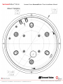
1
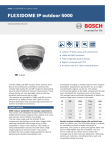
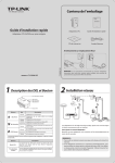
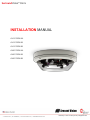
SurroundVideo® Omni INSTALLATION MANUAL AV12176DN-NL AV12176DN-28 AV12176DN-08 AV20175DN-NL AV20175DN-28 AV20175DN-08 SurroundVideo® Omni Arecont Vision SurroundVideo® Omni Installation Manual MicroDome™ Surface Mount Installation Contents Package Contents....................................................................................................................................................... 3 Warranty Information ................................................................................................................................................ 4 Installation Overview ................................................................................................................................................. 5 Camera Setup ............................................................................................................................................................. 6 Camera Adjustment ................................................................................................................................................... 7 Camera Alignment ..................................................................................................................................................... 9 Installation ............................................................................................................................................................... 10 Changing the Lens .................................................................................................................................................... 11 Accessing the Digital Input and Output Connector ................................................................................................. 12 Digital Input and Output .......................................................................................................................................... 13 Auxiliary Power ........................................................................................................................................................ 14 LED Indicators .......................................................................................................................................................... 15 Installation Best Practice.......................................................................................................................................... 17 Wall Mount Accessory (AV-WMJB) .......................................................................................................................... 19 Pendant Mount Accessory (AV-PMJB) ..................................................................................................................... 20 Page | 2 [email protected] SurroundVideo® Omni Arecont Vision SurroundVideo® Omni Installation Manual Package Contents Item MegaPixel Camera Mounting Kit Power Cable I/O Cable Arecont Vision CD Description SurroundVideo® Omni Ceiling template 3x Mounting Screws (#6x1” for wood or sheet metal) 3x Drywall/Masonry Mounting Anchors Ceiling Gasket Network Patch Cable Security Torx Tool Aux Power Cord Digital Input and Output Adapter Manual, Warranty, Installation Software Notes: 1. Camera Operating Temperature : -40°C (-40°F) to +50°C (122°F) 2. Wiring methods shall be in accordance with the National Electrical Code/NFPA 70/ANSI, and with all local codes and authorities having jurisdiction. Wiring should be UL Listed and/or Recognized wire suitable for the application. 3. Always use hardware e.g. screws, anchors, bolts, locking nuts etc. which are compatible with mounting surface and of sufficient length and construction to insure a secure mount. 4. For use in ducts, plenums and other air-handling areas, replace Auxiliary Cable provided with CMP, CL2P or CL3P type wires. Page | 3 [email protected] SurroundVideo® Omni Arecont Vision SurroundVideo® Omni Installation Manual Warranty Information 3 Year Limited Warranty ARECONT VISION warrants to Purchaser (and only Purchaser) (the “Limited Warranty”), that: (a) each Product shall be free from material defects in material and workmanship for a period of thirty-six (36) months from the date of shipment (the “Warranty Period”); (b) during the Warranty Period, the Products will materially conform with the specification in the applicable documentation; (c) all licensed programs accompanying the Product (the “Licensed Programs”) will materially conform with applicable specifications. Notwithstanding the preceding provisions, ARECONT VISION shall have no obligation or responsibility with respect to any Product that (i) has been modified or altered without ARECONT VISION’s written authorization; (ii) has not been used in accordance with applicable documentation; (iii) has been subjected to unusual stress, neglect, misuse, abuse, improper storage, testing or connection; or unauthorized repair; or (iv) is no longer covered under the Warranty Period. ARECONT VISION MAKE NO WARRANTIES OR CONDITIONS, EXPRESS, IMPLIED, STATUTORY OR OTHERWISE, OTHER THAN THE EXPRESS LIMITED WARRANTIES MADE BY ARECONT VISION ABOVE, AND ARECONT VISION HEREBY SPECIFICALLY DISCLAIMS ALL OTHER EXPRESS, STATUTORY AND IMPLIED WARRANTIES AND CONDITIONS, INCLUDING THE IMPLIED WARRANTIES OF MERCHANTABILITY, FITNESS FOR A PARTICULAR PURPOSE, NON-INFRINGEMENT AND THE IMPLIED CONDITION OF SATISFACTORY QUALITY. ALL LICENSED PROGRAMS ARE LICENSED ON AN “AS IS” BASIS WITHOUT WARRANTY. ARECONT VISION DOES NOT WARRANT THAT (I) THE OPERATION OF THE PRODUCTS OR PARTS WILL BE UNINTERRUPTED OR ERROR FREE; (II) THE PRODUCTS OR PARTS AND DOCUMENTATION WILL MEET THE END USERS’ REQUIREMENTS; (III) THE PRODUCTS OR PARTS WILL OPERATE IN COMBINATIONS AND CONFIGURATIONS SELECTED BY THE END USER; OTHER THAN COMBINATIONS AND CONFIGURATIONS WITH PARTS OR OTHER PRODUCTS AUTHORIZED BY ARECONT VISION OR (IV) THAT ALL LICENSED PROGRAM ERRORS WILL BE CORRECTED. For RMA and Advance Replacement information visit ArecontVision.com Page | 4 [email protected] SurroundVideo® Omni Arecont Vision SurroundVideo® Omni Installation Manual Installation Overview Ceiling Gasket NPT Port ( Camera Housing Camera Gimbals (4X) Mounting Screws Gasket Captive Fasteners Page | 5 [email protected] Dome Cover SurroundVideo® Omni Arecont Vision SurroundVideo® Omni Installation Manual Camera Setup The SurroundVideo® Omni is user configurable. Each individual sensor can be positioned in a variety of ways. Below are some example configurations (top left to bottom right) 1. 270° 2. Straight Line 3. 360° or Hallway 4. 180° or Panoramic 5. Random Example 6. Random Example. Tech Tip Page | 6 Prior to installing the camera, thought should be given to the sensor positions. It is always easier to make adjustments before the camera is installed. [email protected] SurroundVideo® Omni Arecont Vision SurroundVideo® Omni Installation Manual Camera Adjustment To position a sensor simply loosen the captive fastener to release the camera assembly from the track plate. #4-40 Screw Captive Fastener Track Plate Next, position the camera in the desired location on the track plate. Screw holes around the circumference are spaced in 5 degree increments. Note the arrows marked at 45 degrees as reference points. 10° 5° 0° Page | 7 [email protected] 45° Reference Mark SurroundVideo® Omni Arecont Vision SurroundVideo® Omni Installation Manual Sensor numbering is indicated on the track plate. The number on the track plate corresponds to the sensor number in the camera software. Tech Tip Page | 8 Sensor positioning and alignment should be considered before camera installation. It is easier to adjust the individual camera positions before the camera is installed into a ceiling. The three slots in the track plate provide additional adjustment of the camera after installation. Simply loosen the three screws to rotate the plate then tighten the three screws after alignment. This feature is most useful for repositioning the cameras mounted to the center locations after camera installation. [email protected] SurroundVideo® Omni Arecont Vision SurroundVideo® Omni Installation Manual Camera Alignment Tech Tip Alignment of the individual cameras is critical to setup. The individual cameras when placed on the circumference of the track must be in a counterclockwise sequence to create proper alignment when viewing the camera. Sensor 2 Sensor 3 Sensor 1 Sensor 4 Counterclockwise Sensor 3 Sensor 4 Sensor 2 Counterclockwise Sensor 1 Page | 9 [email protected] SurroundVideo® Omni Arecont Vision SurroundVideo® Omni Installation Manual Installation 1. Wiring methods shall be in accordance with the National Electrical Code/NFPA 70/ANSI, and with all local codes and authorities having jurisdiction. Wiring should be UL Listed and/or Recognized wire suitable for the application. 2. Operating Temperature -40°C (-40°F) to +50°C (122°F) 3. Always use hardware e.g. screws, anchors, bolts, locking nuts etc. which are compatible with mounting surface and of sufficient length and construction to insure a secure mount 4. Visit http://www.arecontvision.com/ and check to ensure your camera has the most current firmware. 5. If using the NPT port always use Teflon tape around threads to ensure proper sealing. 6. After plugging in the network cable check that the indicator LED’s are indicating the desired conditions (see LED Indicator table). 7. Use Arecont Vision software AV200 located on the CD or available for download at our website (www.arecontvision.com) for camera discovery and setup (see Instruction Manual located on CD or available on our website). 8. Adjust the individual cameras to obtain the desired fields of view (see Focusing Instructions). 9. Lens may be further secured by tightening the lens lock screw using Phillips head screwdriver. 10. Install the Dome Cover by aligning the captive fasteners with the mating threaded holes on the camera housing. 11. When mounting the Dome Cover to the Camera Housing ensure that the gasket is properly seating and not folded. Failure to do so may result in water and dust ingress. Best Practice Tips When mounting to vertical surface it is best to use the Wall Mount Accessory which includes a Junction Box. For outdoor use it is always best to properly seal the product using caulk around the edges to prevent water ingress from mounting to porous or uneven surfaces. Use Teflon tape on threaded interfaces. Page | 10 [email protected] SurroundVideo® Omni Arecont Vision SurroundVideo® Omni Installation Manual Focusing the Cameras Tech Tip 1. Open a live view of the camera from your web browser or the AV Software provided (AV200). 2. Loosen the lens lock screw using a phillips head screwdriver (if necessary). Only do so if lens seems very tight when turning. Lock screw should be tightened enough to provide some friction against the lens to avoid focusing problems. 3. Manually rotate the lens to adjust the focus until the desired image is obtained. 4. For some lenses a focus shift will occur once the bubble is in place. Hold the bubble up to the lens when focusing to account for the focus shift or see the “Focusing Alternate Lenses” section below for further instruction. 5. Retighten the lock screw if necessary. 6. Install the Dome Cover by aligning the captive fasteners with the mating threaded holes on the camera housing. 7. When mounting the Dome Cover to the Camera Housing ensure that the gasket is properly seating and not folded. Failure to do so may result in water and dust ingress. Changing the Lens 1. Remove the Dome Cover by loosening the captive fasteners. 2. Loosen the lens lock screw using a phillips head screwdriver (if necessary). Only do so if lens seems very tight when turning. 3. Manually unscrew the lens, this may take several seconds. 4. Replace lens. 5. Retighten the lock screw if necessary. 6. Reinstall Dome Cover per instructions outlined above. Page | 11 [email protected] SurroundVideo® Omni Arecont Vision SurroundVideo® Omni Installation Manual Focusing Alternate Lenses When focusing the 6mm, 8mm, 12mm or 16mm lens options you will encounter a focus shift when using the bubble. To account for this follow these steps: Tech Tip 1. 2. 3. 4. Focus the camera without the bubble. Rotate the lens per the chart below. The rotation will account for most of the focus shift. Put cover with bubble on. You should be close to being focused. Remove cover and rotate a couple degrees at a time in either direction until you gain the desired image. Lens MPM16.0 MPM12.0 MPM8.0 MPM6.0 16mm 12mm 8mm 6mm Rotation <3/4 CCW 250° 1/4 CCW 90° >1/8 CCW 60° 1/8 CCW 45° Example: Using a 16mm lens you will focus the lens without the bubble until you get the desired image. Rotate the lens almost ¾ of a turn (250°). Put the bubble on and view the image. It should be almost in focus. Remove the bubble and rotate a degree or two in one direction and view the image with the bubble on. Depending on the image you may need to adjust in the opposite direction or continue in the same direction until the desired image is obtained. Accessing the Digital Input and Output Connector The 4 position connector inside camera housing located on the main circuit board used for I/O can be accessed by removing the track plate. Simply loosen the three screws indicated in the image below, lift the track plate and find the connector. The approximate connector position is indicated by the red circle below. Page | 12 [email protected] SurroundVideo® Omni Arecont Vision SurroundVideo® Omni Installation Manual Digital Input and Output Use 4 position connector inside camera housing to interface with Digital I/O. DIGITAL I/O BLACK IN WHITE IN + YELLOW OUT ORANGE OUT + Electrical Characteristics Input Voltage (V) (Measured between + and – terminals) Output Current (mA) (Measured between + and – terminals) Applied Voltage Range : 0-80V MIN MAX ON 2.9 6.3 OFF 0 1.3 ON - 50 OFF - 0.1 NOTE: Both the input and the output are electrically isolated from the rest of the camera’s electrical circuitry via general-purpose photo couplers. The input is additionally protected with a serial 250 Ohm resistor and a debouncing circuit. Duration of any input signal should be at least 5ms to comply with the requirements of the debouncing circuit. Page | 13 [email protected] SurroundVideo® Omni Arecont Vision SurroundVideo® Omni Installation Manual Auxiliary Power If the camera is powered by a separate outside AC or DC power source, run the supplied power cable through the access hole on the camera housing and connect the power cable to the 2-position connector on the main camera board. The approximate location of the 2-position connector is circled in red below. NOTE: Wiring methods shall be in accordance with the National Electrical Code/NFPA 70/ANSI, and with all local codes and authorities having jurisdiction. Wiring should be UL Listed and/or Recognized wire suitable for the application. For use in ducts, plenums and other air-handling areas, replace Auxiliary Cable provided with CMP, CL2P or CL3P type wires. Page | 14 [email protected] SurroundVideo® Omni Arecont Vision SurroundVideo® Omni Installation Manual LED Indicators LED Yellow Status Flashing Green Solid None Flashing Solid None Page | 15 [email protected] Description Link has been established. Normal Operation. No connection. Camera has been accessed. Normal operation. N/A No Connection. SurroundVideo® Omni Arecont Vision SurroundVideo® Omni Installation Manual Support Arecont Vision FAQ Page Located at ArecontVision.com Check the following before you call: Restore camera to factory default with AV100, AV200 or the camera webpage. Upgrade to the latest firmware by visiting ArecontVision.com. Isolate the camera on a dedicated network and test with AV100 or AV200. Swap the “troubled” camera with a known good camera to see if the problem follows the camera or stays at the location. Contact Arecont Vision Technical Support one of three ways: Online Portal : Support.ArecontVision.com Phone : 1.818.937.0700 (option #1) Email : [email protected] Page | 16 [email protected] SurroundVideo® Omni Installation Best Practice Begin Installation Adding Teflon thread sealing tape to all male threads Wind Vinyl electrical tape on all cables connections Connect ¾” NPT conduit pipe to junction box adapter No Does conduit pipe go through the wall? Yes Make sure position of conduit hole is at the lower side forming a “drip loop” below the camera using ¾” galvanized or flex conduit and appropriate fittings Tighten all camera screws and ¾” NPT plugs Caulk the perimeter of the mounting area End Installation Not Recommended! Recommended! Conduct periodic inspections of the installation. Rust on the metal parts or screws may result in damage to camera Not Recommended! Recommended! SurroundVideo® Omni Arecont Vision SurroundVideo® Omni Installation Manual Camera Discovery, Setup, and Configuration For camera discovery and setup please use Arecont Vision software AV200 which you can find on the CD included with your camera or at: http://www.arecontvision.com/softwares.php The user manual for the AV200 software is included on the CD and is also located on our website. To configure the camera use either the AV200 software or the web interface utility. The web interface can be accessed by typing the camera IP address into your web browser or by clicking on the web interface button in AV200. The user manual for our web interface is included on the CD and is also located on our website. Page | 18 [email protected] SurroundVideo® Omni Arecont Vision SurroundVideo® Omni Installation Manual Wall Mount Accessory (AV-WMJB) Gasket -1.5” NPT Gasket Installation Notes: 1. 4x mounting screws are #10x1” wood or sheet metal screws (4x mount anchors also included). 2. Always ensure gaskets are properly seated. 3. Use Teflon tape on threaded interfaces. Page | 19 [email protected] SurroundVideo® Omni Arecont Vision SurroundVideo® Omni Installation Manual Pendant Mount Accessory (AV-PMJB) Gasket Installation Notes: Gasket 1. 4x mounting screws are #10x1” wood or sheet metal screws (4x mount anchors also included). 2. Always ensure gaskets are properly seated. 3. Use Teflon tape on threaded interfaces. -1.5” NPT Page | 20 [email protected] SurroundVideo® Omni Mount Template Page | 21 [email protected] Arecont Vision SurroundVideo® Omni Installation Manual SurroundVideo® Omni Arecont Vision SurroundVideo® Omni Installation Manual Contact Arecont Vision Technical Support one of three ways: Online Portal : Support.ArecontVision.com Phone : 1.818.937.0700 (option #1) Email : [email protected] Page | 22 [email protected]