1
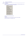
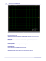
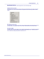
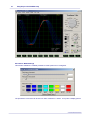
USB Instruments
EasyScope II for DS1M12 "Stingray"
Help
© 2006 USB-Instruments
I
EasyScope II for DS1M12 Help
Table of Contents
3
Part I Introduction
1 Welcome to
...................................................................................................................................
EasyScope II for DS1M12
3
2 EasyScope
...................................................................................................................................
II Features
4
5
Part II Installing EasyScope II
1 Installing the
...................................................................................................................................
EasyScope II Software
5
2 Installing...................................................................................................................................
the USB Drivers
10
13
Part III Using EasyScope II
1 EasyScope
...................................................................................................................................
II Overview
13
2 Front Panel
...................................................................................................................................
Functions
14
Run/Stop.........................................................................................................................................................
and Single Buttons
14
Timebase.........................................................................................................................................................
Settings
15
Input Gain
.........................................................................................................................................................
Settings
16
GND Reference
......................................................................................................................................................... 18
Trigger Settings
......................................................................................................................................................... 19
AC/DC Coupling
......................................................................................................................................................... 22
Invert
......................................................................................................................................................... 23
Output ......................................................................................................................................................... 24
Horizontal.........................................................................................................................................................
Slide Bar
25
XY
......................................................................................................................................................... 26
FFT Display
......................................................................................................................................................... 27
FFT Overview
.................................................................................................................................................. 27
Man
.................................................................................................................................................. 28
Averaging.................................................................................................................................................. 29
Zero Pad.................................................................................................................................................. 30
File Menu.................................................................................................................................................. 32
FFT Window
..................................................................................................................................................
Menu
33
Spectrum..................................................................................................................................................
Menu
34
Signal ......................................................................................................................................................... 35
Meter A and
.........................................................................................................................................................
Meter B
36
Cursor X ......................................................................................................................................................... 38
Cursor A .........................................................................................................................................................
and Cursor B
40
Auto Set ......................................................................................................................................................... 41
3 Menu Functions
................................................................................................................................... 42
File Menu......................................................................................................................................................... 42
Screen Menu
......................................................................................................................................................... 43
Cursors Menu
......................................................................................................................................................... 49
Samples Menu
......................................................................................................................................................... 50
Trigger Menu
......................................................................................................................................................... 51
Tools Menu
......................................................................................................................................................... 52
Help Menu
......................................................................................................................................................... 56
4 Quitting EasyScope
...................................................................................................................................
II
57
© 2006 USB-Instruments
Contents
Part IV Appendix
II
58
1 Error Messages
................................................................................................................................... 58
File Not Found
......................................................................................................................................................... 58
Failed to Configure
.........................................................................................................................................................
DS1M12
59
DS1M12A.........................................................................................................................................................
B Not Found ...
60
FT_Write .........................................................................................................................................................
- General IO Error...
61
FT_GetQueueStatus
.........................................................................................................................................................
- General IO Error...
62
2 Uninstalling
...................................................................................................................................
EasyScope II
63
Index
© 2006 USB-Instruments
65
3
EasyScope II for DS1M12 Help
1
Introduction
1.1
Welcome to EasyScope II for DS1M12
EasyScope II is the easy to use but powerful Digital Sampling Oscilloscope application program for
the USB Instruments DS1M12 Stingray.
It runs on any USB 1.1 or USB 2.0 equipped PC using Windows 98, ME, 2000 or XP.
© 2006 USB-Instruments
Introduction
1.2
EasyScope II Features
·
·
·
·
·
·
·
·
·
·
·
·
·
·
·
·
·
·
·
·
·
Attractive, easy to use visual display
F.F.T. (Fast Fourier Transform) display
2 oscilloscope channels
Advanced trigger settings including edge and pulse triggering
Delayed timebase function
Signal generator
External trigger
Integrated digital Volt meters
Auto Set function
Timebase from 2 ms/div to 50 ms/div
Input ranges from 0.01 V/div to 5 V/div
O.S.D. markers for voltage measurement
O.S.D. markers for time / frequency measurement
Save oscilloscope screens to Windows BMP files
Export 10 most recent oscilloscope traces to CSV file
Screen printout facility
AC/DC coupling support
Support for x1 and x10 probes
User-defined oscilloscope display colour themes
Variable persistence mode display
Load and save colour themes to file
© 2006 USB-Instruments
4
5
EasyScope II for DS1M12 Help
2
Installing EasyScope II
2.1
Installing the EasyScope II Software
Before connecting the instrument to the PC, insert the supplied installation disk into the CD-ROM
drive of your PC. The following menu will appear after a few seconds.
Click on the "Install EasyScope" button to launch the EasyScope installation program. The
following screen will appear:
© 2006 USB-Instruments
Installing EasyScope II
6
Click on the "Next" button to bring up the License Agreement Screen.
If you agree with the terms and conditions of the License Agreement, check the "I agree" box and
© 2006 USB-Instruments
7
EasyScope II for DS1M12 Help
click on the "Next" button to continue the installation process else click on the "Exit" button. The
"Next" button is disabled if you do not agree to the terms and conditions. Agreeing to the terms
and clicking on the "Next" button brings up the following screen.
Select the directory you wish to install the EasyScope software into. A default directory is shown
on the screen. Unless you have good reason to change it we suggest you use the default
suggested by the installation program. Click on the "Next" button to commence copying the files to
the EasyScope program directory.
© 2006 USB-Instruments
Installing EasyScope II
8
A progress screen (shown above) will appear as the files are installed. After a few seconds you
should see the "Installation was completed successfully" message. Click on the "OK" button to
complete the final stage of the installation process.
© 2006 USB-Instruments
9
EasyScope II for DS1M12 Help
The installation process is now complete. You can launch the EasyScope program from the
desktop by double-clicking on the EasyScope icon (pictured below).
You can also launch the EasyScope program from the Start -> Programs -> EasyScope II for
DS1M12 menu on the Windows Toolbar.
As shown above, you also have access to the EasyScope Help files and Program Uninstaller from
there.
Before using EasyScope, the USB drivers need to be installed. This is done by plugging the
instrument into a spare USB port on the PC. The instrument should be plugged into a USB hub
port of your PC or alternatively, a self-powered USB hub (one that has it's own power supply).
If this is the first time that the instrument has been plugged in, Windows will then request the USB
drivers for your product. See Installing the USB Drivers for further details.
© 2006 USB-Instruments
Installing EasyScope II
2.2
10
Installing the USB Drivers
Before using EasyScope the USB drivers need to be installed. This is done by plugging the
instrument into a spare USB port on the PC. The instrument should be plugged into a USB port on
your PC or alternatively, a self-powered USB hub (one that has it's own power supply).
If this is the first time that the instrument has been plugged in, Windows will request the USB
drivers for your product and will display a Found New Hardware Wizard dialog box. The example
below is for Windows 2000 but the procedure is very similar for other Windows versions.
Please note that the instrument uses a single USB connection but has two USB channels that the
driver will install as channel A and channel B.
Connect the instrument to a spare USB port on the PC or self-powered hub. The following screen
will appear to begin guiding you through the driver installation.
Click "Next" to proceed with the installation. The following screen will appear:
© 2006 USB-Instruments
11
EasyScope II for DS1M12 Help
Select the option box for "Search for a suitable driver for my device (recommended)" and click
"Next".
© 2006 USB-Instruments
Installing EasyScope II
12
Check the box for "CD-ROM drives" and un-check all others.
NOTE: If the CD is not available and the EasyScope software has already been installed, then
check the "Specify a location" box and use the Browse button to select the "Drivers\Windows
Drivers" sub-directory of the EasyScope Program Files directory instead.
Keep Clicking on "Next" until the installation is finished as per the screen below.
Click "Finish" to complete the installation of the first device.
If using Windows 2000, the second device will be installed automatically. For other versions of
Windows, the above process may need to be repeated to complete the instrument installation.
© 2006 USB-Instruments
13
EasyScope II for DS1M12 Help
3
Using EasyScope II
3.1
EasyScope II Overview
The EasyScope screen is split into several functional areas as shown in the picture below. The
sections that follow illustrate how to use the settings to control the functions of the instrument.
© 2006 USB-Instruments
Using EasyScope II
3.2
Front Panel Functions
3.2.1
Run/Stop and Single Buttons
14
On starting EasyScope, the program is in idle mode and displays two buttons on the bottom toolbar
with the captions "Single" and "Run". In order to display a trace on the oscilloscope you need to
click on either of the "Run" or "Single" buttons.
On clicking the "Run" or "Single" buttons captured data will be displayed on the screen providing
that the trigger conditions are met or auto trigger is enabled and the trace display buttons are
active.
The "Run" button is used to continuously capture and display data.
When the "Run" button is clicked, the capture / display begins and the caption of the button
changes to "Stop". The "Single" button is "greyed-out" as the two functions are mutually exclusive.
To stop the capture, click on the "Stop" button and the oscilloscope will change back into idle
mode.
The "Single" button captures one screen's worth of data then returns the program to idle mode.
When the "Single" button is clicked, the instrument waits on the trigger conditions being met before
updating the display with a single buffer of data and the caption of the "Run" button changes to
"Stop". The "Single" button is "greyed-out" as the function is currently running. If the instrument
does not trigger, it can be returned to idle mode by clicking the "Stop" button.
The last captured data buffer will remain displayed on the screen as long as the user does not
change any of the oscilloscope settings. If desired, the screen display can be saved to a Windows
Bitmap (.bmp) format file, exported to a comma separated values (.csv) file for analysis using third
party programs or can be printed by any printer connected to the P.C. These subjects are dealt
with in later topics.
An alternative to the Run / Stop button is provided through the File Menu at the top of the
application screen. Click on "File" to select the drop down menu shown below.
Click on "Run" or "Stop" as desired. Clicking on "Exit" will quit the EasyScope application.
© 2006 USB-Instruments
15
3.2.2
EasyScope II for DS1M12 Help
Timebase Settings
The timebase settings are adjusted by clicking on the rotary switch in the Timebase Panel. There
are 14 possible settings ranging from 2 ms/division (fastest) to 50 ms/division (slowest). Please
note, at the lower speed settings there will be a noticeable delay between clicking on the "Run"
button and the trace appearing on the oscilloscope screen. This is because the sampling
(conversion) rate is low and it takes more time to capture a buffers worth of data.
The button for OverSample will become checked for timebase settings of 20ms or less when
triggering on channel A or channel B. Oversampling is disabled for Auto trigger.
When oversampling is active, the display will only show the trace for the channel that is being used
as the trigger source. Oversampling can be turned off by clicking the OverSample control.
The timebase setting changes the sampling rate of the oscilloscope. The sampling rate is
displayed on the bottom right of the oscilloscope panel shown below.
© 2006 USB-Instruments
Using EasyScope II
3.2.3
16
Input Gain Settings
The input gain is adjusted by clicking on the Volts/Div rotary switch on each of the channel settings
control panels shown below. Channels A and B have independent gain settings.
There are 9 gain settings available. Please note that if a gain setting is too high for the input signal,
clipping will occur. To avoid clipping, select a larger voltage scale.
In addition, the settings depend on if the oscilloscope probe used is a x1 (1MW input impedance)
or a x10 (10MW input impedance). If a x10 oscilloscope probe is used then enable the X10 setting
by clicking on the X10 button located below the rotary switch. This will re-scale the switch and
display cursor settings by a factor of 10.
In the picture above, the oscilloscope is setup for a x1 probe. The panel below shows the
oscilloscope setup for a x10 probe.
The current gain setting is also displayed on the bottom right of the oscilloscope panel alongside
the sampling rate. The presence of "X" indicates that the X10 button is active.
© 2006 USB-Instruments
17
EasyScope II for DS1M12 Help
© 2006 USB-Instruments
Using EasyScope II
3.2.4
18
GND Reference
The ground (0V) reference is shown by a small arrow on the left hand side of the screen. The
colour of the arrow matches the colour of the trace display. The default colours are yellow for
channel A and magenta for channel B.
To adjust the ground reference setting, use the "Gnd" buttons on each channel control panel.
Each Gnd reference button will adjust the ground reference for that channel only. The Gnd
reference can be changed both in idle mode and in run mode.
© 2006 USB-Instruments
19
3.2.5
EasyScope II for DS1M12 Help
Trigger Settings
Basic trigger settings are configured using the controls on the trigger panel.
The default trigger mode is for edge triggering. Other trigger modes are explained in the
Trigger Menu section.
Auto
Allows the scope to free-run and constantly collect data without waiting for a trigger event.
ChA
Forces the scope to wait on a trigger event on channel A defined by the other trigger controls
before the display is updated.
ChB
Forces the scope to wait on a trigger event on channel B defined by the other trigger controls
before the display is updated.
Ext
Forces the scope to wait on a level sensitive external trigger event. When this option is selected,
the +ve/-ve button is replaced with a High/Low button (shown below).
This will cause the scope to trigger when the external trigger input signal is above or below the
external trigger level. Please note that this option uses the right hand BNC connector with the
green LED. Setting the external trigger configures the right hand BNC connector as an input.
Consequently, the signal generator output is not available when the DS1M12 is using an external
trigger source. Selecting Ext trigger when the signal generator output is active will stop the signal
output.
The external trigger voltage must be in the range -3.5V to 3.5V.
Select a rising or falling edge event to trigger on by selecting "+ve" (rising edge) (A "+" on the
display indicates +ve edge triggering)
© 2006 USB-Instruments
Using EasyScope II
or "-ve" (falling edge) (A "-" on the display indicates -ve edge triggering).
© 2006 USB-Instruments
20
21
EasyScope II for DS1M12 Help
Use the "Trigger Level" buttons to set the desired trigger level voltage. The trigger level is shown
as an arrow with a "T" to the right of the oscilloscope screen and is displayed numerically above the
plot. The colour of the "T" arrow matches the colour of the trace that has been selected as the
trigger source. If Ext trigger is selected, the "T" arrow colour matches the channel A trace.
When channel A is selected as the trigger source, the trigger line marker on the display is a blue
line. If channel B is selected as the trigger source, the trigger line marker is red. For an external
trigger there is no line.
© 2006 USB-Instruments
Using EasyScope II
3.2.6
22
AC/DC Coupling
AC/DC coupling is controlled by miniature relays inside the oscilloscope. To select AC or DC
coupling click on the AC/DC selector switch on each channel control panel. This will instruct the
oscilloscope to change the coupling from AC to DC or vice-versa for that channel. The current
selection is highlighted in green to the right of the switch.
The above picture shows AC coupling selected.
© 2006 USB-Instruments
23
3.2.7
EasyScope II for DS1M12 Help
Invert
An invert button is located on each of the channel control panels.
Clicking the invert button has the effect of flipping the captured data about the ground reference
value for that channel.
© 2006 USB-Instruments
Using EasyScope II
3.2.8
24
Output
The Output button along with the Ext trigger selection controls the function of the shared BNC
connector to the right of the DS1M12 with the green LED.
The output button is disabled when Ext trigger is selected as this configures the BNC connector as
an input. The Output button determines whether the shared BNC connector is configured as an
input or an output.
If the trigger option is not set to Ext, then the signal generator output may be used. The Output
button enables the signal generator output. The output is active when the blue panel is illuminated.
The output waveform can be configured through the SignalGen option of the Tools menu.
© 2006 USB-Instruments
25
3.2.9
EasyScope II for DS1M12 Help
Horizontal Slide Bar
The horizontal slide bar beneath the plot area may be used to scroll forward and backward through
the data buffer. The trigger point is in the middle of the buffer.
To operate the slide bar, click on the slider (positioned in the centre by default) and drag it to the
desired position. The display will update as this is done.
© 2006 USB-Instruments
Using EasyScope II
26
3.2.10 XY
The XY button changes the trace display from a Voltage versus time (YT) format into a XY format.
Channel A is mapped to the X-axis and Channel B is mapped to the Y-axis.
The XY button changes to a YT button when XY mode is active.
© 2006 USB-Instruments
27
EasyScope II for DS1M12 Help
3.2.11 FFT Display
3.2.11.1 FFT Overview
A fast Fourier transform (FFT) window may be accessed by clicking the FFT Display button.
The FFT window will appear and is shown below.
There are two pairs of cursors which may be used to measure differences in frequency. To the top
of the cursors are marker blocks 1 and 2 for each active trace on the chart. To move a cursor,
place the mouse pointer over the marker block you wish to move, and holding down the left mouse
button drag the cursor to the point you wish to measure.
Channels can be made active or inactive by clicking on the ChA and ChB buttons. The coloured
panel on the button is illuminated when the channel is active.
The units for the vertical scale may be changed between linear and logarithmic units by clicking on
the blue area beneath the chart next to the word "Amplitude".
When the zoom function is active, the scroll bar at the bottom of the plot area may be used to scan
through the FFT data.
© 2006 USB-Instruments
Using EasyScope II
28
3.2.11.2 Man
Clicking the "Man" button in the FFT window enables the up/down buttons and changes the button
caption to "Auto". This allows the vertical scale of the plot to be changed manually.
Clicking on "Auto" will enable autoscaling for the vertical axis.
© 2006 USB-Instruments
29
EasyScope II for DS1M12 Help
3.2.11.3 Averaging
The averaging option may be used to help eliminate noise from measurements.
The averaging options available are off, 5, 10, 20 and 50 sweeps.
© 2006 USB-Instruments
Using EasyScope II
30
3.2.11.4 Zero Pad
Zero padding may be used to artificially increase the number of data points included in the FFT.
The default is no zero padding and using the 1024 points obtained from the data buffer. The FFT
is always 1024 samples around the trigger point even if 2K, 4K or 8K buffer used.
Zero padding will allow the use of either the standard 1K buffer or zero padded 2K, 4K, 8K or 16K
data sets.
Increasing the zero padding has the effect of stretching the frequency axis which will allow more
accurate measurement with the cursors.
The picture below shows the FFT of a 5V 3.472KHz square wave on channel A and a 4V 1KHz
sine wave with no zero padding.
The picture below shows the same input signal with x4 zero padding. The scroll bar at the bottom
of the screen may be used to scroll back and forth through the data buffer.
© 2006 USB-Instruments
31
EasyScope II for DS1M12 Help
© 2006 USB-Instruments
Using EasyScope II
32
3.2.11.5 File Menu
The File menu (shown below) allows access to the two features described below:
Save As
This allows the FFT screen to be saved as a Windows Bitmap (.bmp) file. When selected, a Save
As dialog box appears and prompts the user for a filename.
Print
The print option allows the user to send the FFT screen directly to an installed printer.
© 2006 USB-Instruments
33
EasyScope II for DS1M12 Help
3.2.11.6 FFT Window Menu
The FFT screen display can changed to use a number of different windowing algorithms. The
available windows are displayed when the FFT Window menu is selected (shown below).
The default window is Rectangle.
© 2006 USB-Instruments
Using EasyScope II
34
3.2.11.7 Spectrum Menu
The FFT screen display can be changed to use a number of different ways of scaling the Y-axis
through the spectrum menu.
The available scaling options are Power (V2), Magnitude (mV) and Phase (Rad). As indicated in
the FFT Overview section, by clicking the blue area on the axis of the FFT plot, the units can be
changed between linear and logarithmic for each of these settings.
The default spectrum is Magnitude.
© 2006 USB-Instruments
35
EasyScope II for DS1M12 Help
3.2.12 Signal
The Signal button displays or clears the configuration window for the signal generator output.
Please refer to the Signal Generator section in the Tools menu for more information on the signal
generator functions.
© 2006 USB-Instruments
Using EasyScope II
36
3.2.13 Meter A and Meter B
The "Meter A" and "Meter B" buttons display small panels (shown below) showing 3 measurements
of the data displayed at that time for each channel. The default measurements are mean Voltage,
true RMS Voltage and frequency.
The measurements displayed can be changed by clicking the Configure button at the bottom of the
Meters panel which brings up the following window.
© 2006 USB-Instruments
37
EasyScope II for DS1M12 Help
Available measurements are:
·
·
·
·
·
·
Mean Voltage
True RMS Voltage
Peak to Peak Voltage
Minimum Voltage
Maximum Voltage
Frequency
The meter functions may also be accessed through the Tools menu.
© 2006 USB-Instruments
Using EasyScope II
38
3.2.14 Cursor X
The "Cursor X" button is used to enable or disable the horizontal cursors.
The horizontal cursors may be used to measure the duration of a section of a waveform as shown
below.
The values of the two cursor positions are displayed at the bottom left of the plot area, along with
the difference between them. The difference has a blue background and the units may be
changed by clicking on it. If the display shows time units and the user clicks on it, the units will
change to frequency units.
© 2006 USB-Instruments
39
EasyScope II for DS1M12 Help
Similarly, if the display shows frequency units a click on the blue area will change the units to time
units.
© 2006 USB-Instruments
Using EasyScope II
40
3.2.15 Cursor A and Cursor B
The "Cursor A" and "Cursor B" buttons are used to enable or disable the vertical cursors.
The vertical cursors can be used to measure the voltage difference between two points of a trace
as shown below.
The values of the cursor positions are displayed at the bottom of the plot area, along with the
difference between them.
© 2006 USB-Instruments
41
EasyScope II for DS1M12 Help
3.2.16 Auto Set
Clicking the "Auto Set" button will launch the auto set function. The button caption will read
"Cancel" while the auto set function is running.
The auto set function attempts to home in on a signal and display it clearly on the plot area by
optimising the timebase and gain settings for the detected signal. If no signal is detected, the auto
set function will terminate.
The auto set function may be cancelled by clicking "Cancel".
© 2006 USB-Instruments
Using EasyScope II
3.3
Menu Functions
3.3.1
File Menu
42
The File menu (shown below) allows alternative access to the Run and Stop functions (also
accessible through the Run/Stop button on the front panel).
The Exit option allows the user to quit the application and has the same function as the Windows
Close button .
© 2006 USB-Instruments
43
3.3.2
EasyScope II for DS1M12 Help
Screen Menu
The screen menu (shown below) allows access to options for customising the appearance of the
EasyScope interface and exporting data or images to files.
The menu items have the following functions:
Illuminate
The illuminate option controls the brightness of the grid on the scope display.
With the grid illuminated, it is a bright green colour.
© 2006 USB-Instruments
Using EasyScope II
44
When the grid is not illuminated, it is a dark green. These colours are the default and may be
customised through the Screen Menu options below.
© 2006 USB-Instruments
45
EasyScope II for DS1M12 Help
Save Screen Image to File
This allows the plot area to be saved to a Windows Bitmap (.bmp) file. A Save As dialog box
appears and prompts the user to provide a filename for the image.
Setup Printer
Allows configuration of a printer that is already installed. Options include paper size and
orientation.
Print Screen Image
Sends the plot area of the EasyScope window to the printer.
Print Oscilloscope
Send the whole EasyScope window image to the printer.
Load Background from file
Allows the user to load a bitmap image as the background for the plot area.
© 2006 USB-Instruments
Using EasyScope II
46
Save background to File
Allows the user to save the current background to a file as a bitmap image.
Customise Screen Colours
This brings up a sub-menu (shown below) that allows full customisation of the colours, fonts and
backgrounds used. Colours can be reset to the original scheme by selecting "Restore Default
Colors".
Save Screen Colors to File
The Customize Screen Colors menu can be used to select the display color theme which can then
be saved to file (*.col). Different colors can be used in 'Illuminate' and non Illuminate modes.
Persistence Mode
A variable persistence mode display can be selected using this option. The persistence increment,
decrement and colors are selected in the Persistence Mode Setup window. Infinite persistence
can be selected by setting the persistence decrement to 0.
© 2006 USB-Instruments
47
EasyScope II for DS1M12 Help
Persistence Mode Settings
This window enables the variable persistence mode options to be configured.
The persistence increment can be set to a value of between 1 and 64. Every time a display pixel is
© 2006 USB-Instruments
Using EasyScope II
48
activated by the oscilloscope trace the 'persistence value' of that pixel is incremented by the
persistence increment value. The maximum 'persistence value' is limited to 127.
The persistence decrement can be set to a value of between 0 and 15. The persistence
decrement value is also limited to the persistence increment value - 1. The persistence value of
every pixel is decremented by the persistence decrement value after a trigger and trace display
event. The minimum 'persistence value' is limited to 0.
Eight different colors can be selected to display a certain persistence value range. The colors for
each pixel value range can be changed by clicking on the color box and selecting an alternative
color from the color selection menu. The default persistence mode colors can be restored by
clicking on the 'Restore Default Colors' button.
Save To CSV Text File
This option exports the ten most recent oscilloscope traces to a comma separated values (.csv)
file. Column A contains the most recent trace for Channel A while column B contains the most
recent trace for Channel B. Columns S and T contain the oldest trace data for Channel A and
Channel B respectively. This can be used with 3rd party programs (for example Microsoft Excel) to
manipulate and re-plot the data. The plot below was obtained from Excel using an exported .csv
file.
In addition, it is possible to save a scope trace to a .CSV file and use this as the source for the
signal generator custom waveform. The data in column A (most recent trace from Channel A) of
this file is used by the signal generator.
© 2006 USB-Instruments
49
3.3.3
EasyScope II for DS1M12 Help
Cursors Menu
The options in the Cursors menu (shown below) have the same functions as the Cursor X,
Cursor A and Cursor B buttons respectively.
© 2006 USB-Instruments
Using EasyScope II
3.3.4
50
Samples Menu
The Samples Menu can be used to change the data buffer size.
Increasing the data buffer size provides a larger trace display but can produce long acquisition
times at slow timebase settings.
© 2006 USB-Instruments
51
3.3.5
EasyScope II for DS1M12 Help
Trigger Menu
In addition to the basic trigger settings available on the front panel, this menu (shown below) allows
advanced triggering options to be configured.
The default mode is edge triggering which can be set to trigger on a +ve (rising) or -ve (falling)
edge using the front panel controls.
Pulse
Selecting Pulse from this menu disables edge triggering and enables pulse triggering. The user
must select either Negative or Positive pulse from a sub menu (see below) and is then provided
with an Advanced Trigger window (also below).
The example shown is for a negative pulse.
The user can then select options to trigger on a pulse of length greater than or less than the time
indicated by the top slide bar. The value of the slide bar is displayed in the box to the right and
may be changed by clicking on and dragging the slider.
This triggering method can be an extremely useful tool for finding "glitches".
Delay From Trigger
The Delay From Trigger option also displays the Advanced Trigger and Delayed TimeBase Options
window. This allows the data capture to be delayed from the trigger point by a specified time by
using the by using the Delay From Main Time Base slide bar.
.
© 2006 USB-Instruments
Using EasyScope II
3.3.6
52
Tools Menu
Several functions are available through the Tools menu (shown below)
Meter CHA
The Meter A option provides the same functionality as the Meter A button. This makes the meter
window for channel A visible.
Meter CHB
The Meter B option provides the same functionality as the Meter B button. This makes the meter
window for channel B visible.
Set CHA GND Adjust
The impedance of the USB ground lead can require a small adjustment to the ground used by the
oscilloscope. The Set ChA GND Adjust option enables the user to auomatically adjust the ground
point for sensitive measurements. When selected, the following message will appear:
Connect a scope probe set to x1 gain and connect the probe tip and probe ground lead to an
external ground reference. After clicking "OK", the scope performs a routine in which it cycles
through each input gain setting the adjusted ground level.
When the ground offset has been set, the V/Div text shown on the oscilloscope display is shown on
a red background.
Clear CHA GND Adjust
Selecting this option will remove any active ground level adjustment from the measurements for
channel A.
Set CHB GND Adjust
© 2006 USB-Instruments
53
EasyScope II for DS1M12 Help
The impedance of the USB ground lead can require a small adjustment to the ground used by the
oscilloscope. The Set ChB GND Adjust option enables the user to auomatically adjust the ground
point for sensitive measurements. When selected, the following message will appear:
Connect a scope probe set to x1 gain and connect the probe tip and probe ground lead to an
external ground reference. After clicking "OK", the scope performs a routine in which it cycles
through each input gain setting the adjusted ground level.
When the ground offset has been set, the V/Div text shown on the oscilloscope display is shown on
a red background.
Clear CHB GND Adjust
Selecting this option will remove any active ground level adjustment from the measurements for
channel B.
SignalGen
Selecting the SignalGen option from the tools menu displays the configuration window for the
signal generator output (shown below).
This allows the operator to select a pre-defined waveform from
·
DC output
© 2006 USB-Instruments
Using EasyScope II
·
·
·
·
·
54
Sawtooth
Square
Sine
Triangle
Pulse
Each of these waveforms may be adjusted in amplitude, ground offset and frequency. In addition,
there is an option to load a custom waveform from a .CSV file. This file should have one column of
millivolt values, one for each sample. The maximum number of samples permitted is 1024. It is
possible to save a scope trace to a .CSV file and then use this file as the source for the signal
generator custom waveform (from channel A data). If the file contains more than 1024 data points,
only the first 1024 points will be used to generate the pattern.
The signal generator operates from a 500kHz clock. The frequency dial selects a divider of
between 1 and 255 that is applied to the 500kHz clock. The output frequency is also dependent on
the number of samples selected. The output frequency is given by:
Output Frequency = 500kHz / (Divider * Samples)
For small divider values the output frequency changes can be large. For example:
Samples = 16 and Divider = 2 gives an Output Frequency of 15625Hz
Samples = 16 and Divider = 3 gives an Output Frequency of 10417Hz
Consequently small frequency dial changes can result in large output frequency changes,
especially with small divider values. An Auto samples option is available that automatically sets the
number of samples to provide a more linear response to frequency dial changes.
The output from the signal generator will not be active until the Output button is active and the
scope has triggered (if it is running). Also, the signal generator output will not be available when an
external trigger source is being used.
Test Mode
In test mode the EasyScope does not acquire real data but provides simulated data from a counter.
This allows the communication with the PC to be verified. The display observed in test mode
should always be a saw tooth type wave with clipping occurring (see picture below). The wave is at
a frequency of 244.1Hz.
© 2006 USB-Instruments
55
EasyScope II for DS1M12 Help
Test mode must be disabled to acquire real data.
© 2006 USB-Instruments
Using EasyScope II
3.3.7
56
Help Menu
The following options are available through the Help menu (shown below).
HTML Help
Selecting HTML Help from the menu will launch this help file.
About ...
The About ... option displays version information and release dates.
USB-Instruments Web Site
This will connect to the Internet and take the user directly to the USB Instruments web site where
information can be found on products and updates.
On-Line User Manual
This option will take the user to the EasyScope II manual section of the USB Instruments web site.
On-Line F.A.Q.
This link will open the frequently asked questions (F.A.Q.) section of the USB Instruments web site.
© 2006 USB-Instruments
57
3.4
EasyScope II for DS1M12 Help
Quitting EasyScope II
EasyScope can be exited by either accessing the Exit option of the File menu or clicking the
Windows Close button
in the top right-hand corner of the window.
© 2006 USB-Instruments
Appendix
4
Appendix
4.1
Error Messages
4.1.1
File Not Found
58
This error occurs when EasyScope II cannot find the file to program the DS1M12 hardware.
To resolve this problem click "OK", quit the EasyScope application and check that the files
DS1M12_1k.rbf, DS1M12_2k.rbf, DS1M12_4k.rbf and DS1M12_8k.rbf exist in the same directory
as the EasyScope application program. If the files are there, try to re-launch the EasyScope
application ensuring that the instrument is connected to the PC. If the files are not there, it may be
retrieved by re-installing from the installation CD.
© 2006 USB-Instruments
59
4.1.2
EasyScope II for DS1M12 Help
Failed to Configure DS1M12
This error occurs when the EasyScope II application cannot detect any DS1M12 instruments
connected to the PC when it is launched.
Ensure that the instrument is connected to the PC and that the correct drivers are installed, then
re-launch the EasyScope II application.
© 2006 USB-Instruments
Appendix
4.1.3
60
DS1M12A B Not Found ...
This error can occur when trying to run the EasyScope application with no DS1M12 hardware
connected to the PC.
To resolve this, connect a DS1M12 to the PC and run the application again. If this has no effect,
check that the drivers are installed correctly.
© 2006 USB-Instruments
61
4.1.4
EasyScope II for DS1M12 Help
FT_Write - General IO Error...
This error may occur if the DS1M12 is unexpectedly disconnected from the PC while the program
is running.
A message box with this error may appear several times but will clear and run as normal after
clicking "OK" on each message box that appears.
© 2006 USB-Instruments
Appendix
4.1.5
62
FT_GetQueueStatus - General IO Error...
This error may occur if the DS1M12 is unexpectedly disconnected from the PC while the program
is running.
A message box with this error may appear several times but will clear and run as normal after
clicking "OK" on each message box that appears.
© 2006 USB-Instruments
63
4.2
EasyScope II for DS1M12 Help
Uninstalling EasyScope II
From the Start -> Programs -> EasyScope II for DS1M12 menu on the Windows Toolbar, select
the Uninstall DS1M12 Option and click on it.
This will start the uninstaller program. The following confirmation screen will appear.
If you are sure you want to uninstall the EasyScope Program, click on "Next". If not, click on
"Cancel" to abort the Uninstall process.
Clicking on "Next" starts the uninstall sequence. When the EasyScope Software is run for the first
time, it automatically creates an INI file (easyscope.ini) to store program settings and two BMP files
(DSBright.bmp and DSNormal.bmp) containing the images of the Normal and Bright screen
themes. It is safe to delete these if asked by the uninstaller. In the course of using EasyScope the
user may have saved some screen images and should decide if they want to keep these or not.
© 2006 USB-Instruments
Appendix
Click on "Finish".
© 2006 USB-Instruments
64
EasyScope II for DS1M12 Help
65
Index
-11k
50
-22k
50
-44k
50
-88k
50
-AA 40
A Cursor 40
about 56
AC 22
acquire 14, 42
active 24
adjust 41
auto 19, 41, 51
automatic 41
automatically 41
average 29
averaging 29
-BB 40
B Cursor 40
background 43
bar 25
Blackman 33
buffer 25, 50
-Ccapture 14, 42
CHA 19, 51
clipping 16, 52
color 43
colour 43
control 13, 15, 16, 19, 22, 23, 24, 25, 26, 27, 28,
29, 30, 32, 33, 34, 36, 38, 40, 41, 51
controls 13
cos 33
cos2 33
coupling 22
csv 43
Cur 38, 49
Cur A 49
Cur Horiz 38, 49
cursor 27, 38, 40, 49
customise 43
customize 43
-Ddata 25, 30
dB 34
DC 22
delay 19, 51
delayed 19, 51
detect 41
difference 38, 40, 49
display 26
divisions 15, 16
driver 5, 10
drivers 5, 10
DS1M12 3, 4, 5, 10, 13, 14, 15, 16, 18, 19, 22, 23,
24, 25, 26, 27, 28, 29, 30, 32, 33, 34, 36, 38, 40, 41,
42, 43, 49, 50, 51, 52, 56, 57, 58, 59, 60, 61, 62, 63
DS1M12_1k.rbf 58
DS1M12_2k.rbf 58
DS1M12_4k.rbf 58
DS1M12_8k.rbf 58
DS1M12A 60
DS1M12A B not found 60
duration 38, 49
© 2006 USB-Instruments
Index
-E-
-I-
easyscope 3, 4, 5, 10, 13, 14, 15, 16, 18, 19, 22,
23, 24, 25, 26, 27, 28, 29, 30, 32, 33, 34, 38, 40, 41,
42, 43, 49, 51, 52, 56, 57, 58, 59, 60, 61, 62, 63
edge 19, 51
error 58, 59, 60, 61, 62
exit 14, 42, 57
-Ffailed 59
failed to configure DS1M12 59
fast 27, 28, 29, 30, 32, 33, 34
fast Fourier transform 27, 28, 29, 30, 32, 33, 34
features 4, 13
FFT 27, 28, 29, 30, 32, 33, 34
file 43, 58
file not found 58
found 58, 60
Fourier 27, 28, 29, 30, 32, 33, 34
frequency 27, 28, 29, 30, 32, 33, 34, 38, 49, 52
FT_GetQueueStatus 62
FT_Write 61
function 24, 27, 28, 29, 30, 32, 33, 34
functions 13
-Ggain 16, 41
Gauss 33
General IO Error
generator 24
GND 18
ground 18
61, 62
-HHamming 33
hardware 59
help 56
Horiz 38, 49
horizontal 25, 38, 49
HTML 56
HTML help 56
© 2006 USB-Instruments
66
illuminate 43
image 43
impedance 22
input 22
install 5, 10, 63
installation 5, 10, 63
installing 5, 10, 63
instrument 13, 14, 15, 16, 18, 19, 22, 23, 25, 26,
27, 28, 29, 30, 32, 33, 34, 36, 38, 40, 41, 42, 43, 49,
51, 52, 56, 57, 58, 59, 60, 61, 62, 63
introduction 3
inverse 23
invert 23
IO 61, 62
-Llevel 19, 51
linear 34
log 34
logarithmic 34
-Mmagnitude 34
manual 28
max 52
maximum 52
mean 52
measure 38, 40
menu 42, 50
meter 52
Meter A 36
Meter A button 36
Meter B 36
Meter B button 36
meters 36, 52
min 52
minimum 52
mode 52
mV 18, 19, 51
EasyScope II for DS1M12 Help
67
-Nnegative
19, 51
-Ooffset 18
on-line 56
output 24
overview 3, 13
-Ppad 30
padding 30
peak 52
peak-to-peak 52
phase 34
picture 43
points 30
positive 19, 51
power 34
print 32, 43
program 59
pulse 19, 51
-Qquit
57
-Rrectangle 33
reference 18
remove 63
RMS 52
root 52
run 14, 42
-Ssamples 50
save 32, 43
save as 32, 43
scale 15, 16, 18, 28
scroll 25
seek 41
set 41
signal 24
Signal generator 35
single 14, 42
size 30, 50
slide 25
software 5, 13, 14, 15, 16, 18, 19, 22, 23, 24, 25,
26, 27, 28, 29, 30, 32, 33, 34, 38, 40, 41, 42, 43, 49,
51, 52, 56, 57, 58, 59, 60, 61, 62, 63
specification 3, 4
spectrum 34
square 52
stingray 3, 4, 5, 10, 13, 14, 15, 16, 18, 19, 22, 23,
24, 25, 26, 27, 28, 29, 30, 32, 33, 34, 36, 38, 40, 41,
42, 43, 49, 50, 51, 52, 56, 57, 58, 59, 60, 61, 62, 63
stop 14, 42
-Tt/div 15
test 52
time 15, 38, 49
timebase 15, 41
timing 38
Timing Cursor 38
tools 52
transform 27, 28, 29, 30, 32, 33, 34
triangle 33
trigger 19, 51
-Uuninstall 63
un-install 63
uninstallation 63
un-installation 63
uninstalling 63
un-installing 63
USB 10
usb instruments 56
user 56
user manual 56
© 2006 USB-Instruments
Index
-Vv/div 16
vertical 28, 40, 49
volt 52
voltage 16, 40, 49, 52
volts 16, 40, 49, 52
-Wweb 56
web site 56
width 19, 51
window 27, 33
wizard 10
-XXY Mode
26
-Zzero
18, 30
© 2006 USB-Instruments
68