1
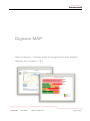
Digicom MAP
User manual - master data management and station
display for version 1.6.1
Digicom MAP
User manual
Version 1.0.0 for V1.6.1
Page 1 of 49
Introduction
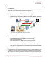
Digicom MAP is part of a RES.Q solution for alarms with confirmation.
It has been developed in-house by Swissphone for the confirmation server (see Fig. 1) and comprises the following functional elements
R module as the interface to the RES.Q terminal via GSM
Database with the master data on the terminals, forces and their structure
Web application with user interface for displaying confirmations and master data management
Fig. 1: General overview of RES.Q solution "Alarms with confirmation"
Digicom MAP specifications
Confirmations received and processed
Master data database and management
Confirmations displayed in a table as well as on the map as an option
Option of exporting the alarms list
Status messages displayed in a table as well as on the map as an option
Option of exporting the current status messages
Strength message: analysis of the confirmations, displayed as a bar chart
Status messages: analysis of the active status profiles, displayed as a bar chart
Option: Alarm calls received directly from the POCSAG network and displayed immediately
via an additional module
Use in fire stations
The strength message with confirmations displayed as a bar chart is specially designed for use in
fire stations. The information is shown on a large display as a preference. A purely web-based solution and stand-alone solutions are available. Forwarding/connection to the control centre is dispensed with. This simplifies the system structure as no action is needed from the dispatch system.
Digicom MAP
User manual
Version 1.0.0 for V1.6.1
Page 2 of 49
Changes in comparison with Digicom MAP 1.4 version
Bar chart display under Confirmations, Diagram for statistical analysis works in the same way
as the alarms display
If there are no alarms, availability display (pager profiles) on the station display via the Device
profile screen. Up to 8 profiles can be defined
Display and analysis of up to 8 individual acknowledgements via the Acknowledgements screen
Time span of the alarm summary can be configured via the Configuration screen
Time span of the alarm display can be configured via the Configuration screen
POCSAG font can be set via the Customer screen
The Digicom MAP language can be customised on a user-specific basis via the Users screen
Export functions on the basis of XML/XSD of master data, alarm list, and actual profiles
Digicom MAP
User manual
Version 1.0.0 for V1.6.1
Page 3 of 49
Contents
Introduction ....................................................................................................................... 2
Changes in comparison with Digicom MAP 1.4 version ..................................................... 3
1.
2.
3.
4.
General conventions................................................................................................... 9
1.1
Names of elements ........................................................................................................... 9
1.2
Warnings ........................................................................................................................... 9
1.3
Information ........................................................................................................................ 9
Field and button names ............................................................................................ 10
2.1
General ............................................................................................................................ 10
2.2
Pushbuttons .................................................................................................................... 10
2.2.1 New .................................................................................................................... 10
2.2.2 Save ................................................................................................................... 10
2.2.3 Edit ..................................................................................................................... 11
2.2.4 Cancel ................................................................................................................ 11
2.2.5 Delete ................................................................................................................. 11
Technical requirements ............................................................................................ 12
3.1
Hosting ............................................................................................................................ 12
3.2
Operating the station display ........................................................................................... 12
3.2.1 Minimum hardware required ............................................................................... 12
3.2.2 Minimum software required ................................................................................ 12
Installing Digicom MAP ............................................................................................. 13
4.1
5.
Digicom MAP
Browser security settings ................................................................................................ 13
4.1.1 JavaScript ........................................................................................................... 13
4.1.2 Information on security messages when loading the map view ......................... 13
Using Digicom MAP.................................................................................................. 14
5.1
Opening the web interface .............................................................................................. 14
5.1.1 Hosting with Swissphone Telecom AG .............................................................. 14
5.1.2 Hosting with a different system provider ............................................................ 14
5.1.3 Hosting as an autonomous solution in the fire station........................................ 14
5.2
Logging on ....................................................................................................................... 14
5.2.1 Login data, administrator .................................................................................... 15
5.2.2 Login data, write access ..................................................................................... 15
5.2.3 Login data, read access ..................................................................................... 15
5.3
Alarms with confirmation ................................................................................................. 15
5.4
Status queries and status messages .............................................................................. 16
5.4.1 Exporting the status messages .......................................................................... 17
User manual
Version 1.0.0 for V1.6.1
Page 4 of 49
6.
5.5
Alarm messages .............................................................................................................. 18
5.5.1 Exporting the alarm list ....................................................................................... 19
5.6
Strength message/availability report ............................................................................... 20
5.6.1 Strength message .............................................................................................. 20
5.6.2 Availability report ................................................................................................ 21
Master data management ......................................................................................... 22
6.1
7.
Digicom MAP
Digicom MAP management quick reference guide ......................................................... 23
6.1.1 Recommended application workflow .................................................................. 23
6.1.2 Preparing personal details and alarm data ........................................................ 24
6.1.2.1
Managing terminals (RES.Q pagers) ............................................... 24
6.1.2.2
Managing forces (device users) ....................................................... 24
6.1.2.3
Creating functions ............................................................................ 24
6.1.2.4
Group RICs – assigning the RICs and forces to the groups ............ 24
6.1.2.5
Other functions ................................................................................. 24
Reference manual .................................................................................................... 25
7.1
Creating a new customer ................................................................................................ 25
7.1.1 Company* ........................................................................................................... 26
7.1.2 Service ................................................................................................................ 26
7.1.2.1
BackChannelNoMap ........................................................................ 27
7.1.2.2
BackChannelSmallMap .................................................................... 27
7.1.2.3
BackChannelBigMap ....................................................................... 28
7.1.2.4
StrengthView .................................................................................... 28
7.1.3 Position IMASYS Account .................................................................................. 29
7.1.4 Position IMASYS Password ............................................................................... 29
7.1.5 Info IMASYS Account ......................................................................................... 29
7.1.6 Info IMASYS Password ...................................................................................... 29
7.1.7 Locator Account .................................................................................................. 29
7.1.8 Locator Password ............................................................................................... 29
7.1.9 Windows user ..................................................................................................... 29
7.1.10 Inbound Keyword/Modem .................................................................................. 29
7.1.11 License ............................................................................................................... 29
7.1.12 Refresh Rate ...................................................................................................... 30
7.1.13 Position as aged ................................................................................................. 30
7.1.14 Start Position Latitude / Longitude / Zoom* ........................................................ 30
7.1.14.1
Large map window, 5km grid (Start Position Zoom: 10) .................. 30
7.1.14.2
Large map window, 1km grid (Start Position Zoom: 13) .................. 30
7.1.15 Language ............................................................................................................ 30
7.1.16 Character set ...................................................................................................... 30
7.1.17 Various ............................................................................................................... 31
7.1.18 ForeignId ............................................................................................................ 31
7.1.19 Logo .................................................................................................................... 31
7.1.20 Symbols .............................................................................................................. 31
7.2
Users ............................................................................................................................... 32
7.2.1 Last Name* ......................................................................................................... 32
User manual
Version 1.0.0 for V1.6.1
Page 5 of 49
7.2.2
7.2.3
7.2.4
7.2.5
7.2.6
7.2.7
7.2.8
7.2.9
First Name .......................................................................................................... 32
Function .............................................................................................................. 32
Department ......................................................................................................... 32
User Name* ........................................................................................................ 33
Password* .......................................................................................................... 33
Message Sender Name ...................................................................................... 33
Language ............................................................................................................ 33
Rights ................................................................................................................. 33
7.2.9.1
Read ................................................................................................. 33
7.2.9.2
Write ................................................................................................. 33
7.2.9.3
Administrator .................................................................................... 34
7.2.10 Status ................................................................................................................. 34
7.2.10.1
Active ............................................................................................... 34
7.2.10.2
Blocked ............................................................................................ 34
7.2.11 Information Intervals ........................................................................................... 34
7.2.12 Send Strength Message ..................................................................................... 34
Digicom MAP
7.3
Additional users ............................................................................................................... 34
7.4
Configuration ................................................................................................................... 35
7.4.1 Time span for message mapping ....................................................................... 35
7.4.2 Time span for strength analysis display ............................................................. 35
7.4.3 Language ............................................................................................................ 35
7.5
Terminals ......................................................................................................................... 36
7.5.1 Description* ........................................................................................................ 36
7.5.2 Phone No. ........................................................................................................... 36
7.5.3 Serial Number..................................................................................................... 36
7.5.4 Status ................................................................................................................. 36
7.5.4.1
Active ............................................................................................... 36
7.5.4.2
Inactive ............................................................................................. 36
7.5.5 Various ............................................................................................................... 37
7.5.6 ForeignId ............................................................................................................ 37
7.6
Forces.............................................................................................................................. 37
7.6.1 Last Name .......................................................................................................... 37
7.6.2 First Name .......................................................................................................... 37
7.6.3 Mobile ................................................................................................................. 37
7.6.4 Pager No. ........................................................................................................... 37
7.6.5 Terminal .............................................................................................................. 38
7.6.6 (Link) Go to terminal ........................................................................................... 38
7.6.7 Status ................................................................................................................. 38
7.6.7.1
Active ............................................................................................... 38
7.6.7.2
Inactive ............................................................................................. 38
7.6.8 Various ............................................................................................................... 38
7.6.9 ForeignId ............................................................................................................ 38
7.7
Group RIC ....................................................................................................................... 39
7.7.1 Group Name ....................................................................................................... 39
7.7.2 RICs .................................................................................................................... 39
User manual
Version 1.0.0 for V1.6.1
Page 6 of 49
7.7.3
7.7.4
7.7.5
7.7.6
7.7.7
7.7.8
7.7.9
Sub Address ....................................................................................................... 39
AdC ..................................................................................................................... 39
Pattern ................................................................................................................ 40
ForeignId ............................................................................................................ 40
Entering members .............................................................................................. 40
Entering managers ............................................................................................. 40
(Link) Edit Group Device .................................................................................... 41
7.8
RICs................................................................................................................................. 41
7.8.1 RICs .................................................................................................................... 41
7.8.2 Sub Address ....................................................................................................... 42
7.8.3 Entering members .............................................................................................. 42
7.9
Functions ......................................................................................................................... 42
7.9.1 Function .............................................................................................................. 42
7.9.2 Priority ................................................................................................................ 43
7.9.3 Entering members .............................................................................................. 43
7.10 Acknowledgements ......................................................................................................... 43
7.10.1 Index ................................................................................................................... 44
7.10.2 Active .................................................................................................................. 44
7.10.3 Text ..................................................................................................................... 44
7.10.4 Symbol ................................................................................................................ 44
7.10.5 Color ................................................................................................................... 44
7.10.6 Unavailable ......................................................................................................... 44
7.11 Device profile ................................................................................................................... 45
7.11.1 Deactivate strength analysis display .................................................................. 45
7.11.2 ID ........................................................................................................................ 45
7.11.3 Text ..................................................................................................................... 45
7.11.4 Color ................................................................................................................... 45
7.12 Possible Alarms ............................................................................................................... 46
7.12.1 Group Name ....................................................................................................... 46
7.12.2 RICs .................................................................................................................... 46
7.12.3 Alarm Text .......................................................................................................... 46
7.12.4 Timeout ............................................................................................................... 46
7.12.5 Functions ............................................................................................................ 47
7.13 Networks.......................................................................................................................... 47
7.13.1 Network Name .................................................................................................... 47
7.13.2 Number ............................................................................................................... 47
7.14 Group Structure ............................................................................................................... 47
7.14.1 Export ................................................................................................................. 47
7.15 Import Core Data ............................................................................................................. 47
7.16 Search ............................................................................................................................. 47
Digicom MAP
User manual
Version 1.0.0 for V1.6.1
Page 7 of 49
Illustrations
Fig. 1: General overview of RES.Q solution "Alarms with confirmation" ........................................... 2
Fig. 2: Digicom MAP GUI ................................................................................................................. 10
Fig. 3: Pushbuttons for entering/editing/deleting entries .................................................................. 10
Fig. 4: Digicom MAP homepage ...................................................................................................... 14
Fig. 5: Display of the alarms and confirmations ............................................................................... 15
Fig. 6: Status display ........................................................................................................................ 16
Fig. 7: Export function with calendar ................................................................................................ 17
Fig. 8: List of alarms (overview) ....................................................................................................... 18
Fig. 9: Export of alarm list ................................................................................................................ 19
Fig. 10: Alarm display with strength message ................................................................................. 20
Fig. 11: Alarm display with availability report ................................................................................... 21
Fig. 12: Excerpt from the master data management menu.............................................................. 22
Fig. 13: Recommended Digicom MAP application workflow ............................................................ 23
Fig. 14: Alarm display with strength message ................................................................................. 25
Fig. 15: Customers screen ............................................................................................................... 26
Fig. 16: Backchannel without map ................................................................................................... 27
Fig. 17: Backchannel with small map ............................................................................................... 27
Fig. 18: Backchannel with big map .................................................................................................. 28
Fig. 19: Strength view display .......................................................................................................... 28
Fig. 20: Customer screen ................................................................................................................. 32
Fig. 21: Configuration screen ........................................................................................................... 35
Fig. 22: Manage Terminals screen................................................................................................... 36
Fig. 23: Manage Forces screen ....................................................................................................... 37
Fig. 24: Group RICs screen ............................................................................................................. 39
Fig. 25: Manage Terminals screen................................................................................................... 41
Fig. 26: Functions screen ................................................................................................................. 42
Fig. 27: Acknowledgements screen ................................................................................................. 43
Fig. 29: Assignment in the PSW ...................................................................................................... 44
Fig. 28: Assignment in Digicom MAP ............................................................................................... 44
Fig. 30: Assignment in Digicom MAP ............................................................................................... 45
Fig. 31: Assignment in the PSW ...................................................................................................... 45
Digicom MAP
User manual
Version 1.0.0 for V1.6.1
Page 8 of 49
1.
General conventions
1.1
Names of elements
Names of elements of the software are written in cursive in this manual.
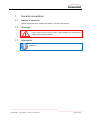
1.2
Warnings
Actions which could result in damage to the software or hardware or that
have an effect on the correct function of the software are marked with a
danger symbol and a red frame.
1.3
Information
Information and special tips are marked with an information symbol and a
blue frame.
Digicom MAP
User manual
Version 1.0.0 for V1.6.1
Page 9 of 49
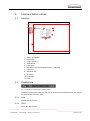
2.
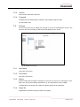
Field and button names
2.1
General
1
2
4
6
5
7
3
8
9
10
11
Fig. 2: Digicom MAP GUI
1.
2.
3.
4.
5.
6.
7.
8.
9.
10.
11.
2.2
Hidden pushbutton
Pushbutton
Image (graphic)
Selection list
Field name
Mandatory input field (flagged with an * (asterisk))
Input field
Dropdown list
Checkbox
Pushbutton
Form
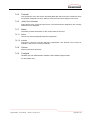
Pushbuttons
Fig. 3: Pushbuttons for entering/editing/deleting entries
Pushbuttons with white writing are active and can be used. Pushbuttons with grey writing
are inactive and cannot be used.
2.2.1
New
Creates a new resource.
2.2.2
Save
Saves the data entered.
Digicom MAP
User manual
Version 1.0.0 for V1.6.1
Page 10 of 49
2.2.3
Edit
Opens the selected, existing data record for editing. The changes made are only adopted
after Save has been pressed.
2.2.4
Cancel
Cancels the operation.
If the user wants to add a new resource, the data on the form that has already been entered is discarded. If the user wants to edit existing data, the changes to the data record
are not adopted.
2.2.5
Delete
Deletes the selected data record from the database.
The data is deleted without a query after Delete has been pressed.
Digicom MAP
User manual
Version 1.0.0 for V1.6.1
Page 11 of 49
3.
Technical requirements
3.1
Hosting
For more information on the technical requirements for hosting the Digicom MAP web
services, please refer to the Digicom MAP: Super User manual.
3.2
Operating the station display
3.2.1
Minimum hardware required
Computer with network access to the Digicom MAP server and monitor output.
Large display with appropriate monitor input (e.g. VGA, DVI, HDMI).
3.2.2
Minimum software required
Network-compatible and internet-compatible operating system with web browser. The
web browser must support XHTML 1.1 and JavaScript.
Digicom MAP
User manual
Version 1.0.0 for V1.6.1
Page 12 of 49
4.
Installing Digicom MAP
Digicom MAP is a server-based programme. This means that only a browser has to be
installed on the working computer. Every other access to Digicom MAP is made via the
browser.
4.1
Browser security settings
4.1.1
JavaScript
The browser must support JavaScript and have activated it. In some circumstances, Microsoft calls this function Active Scripting.
To activate JavaScript, please refer to the help function of the browser concerned and
any support forums operated by the manufacturer of the browser.
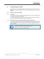
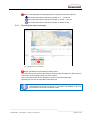
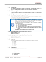
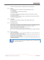
4.1.2
Information on security messages when loading the map view
When logging on to Digicom MAP, a security message may appear while the map is loading. This message points out that contents of the website are not transmitted via a secure
HTTPS connection. The user must respond to the message, enabling all website contents to be loaded.
The warning about website contents that are not transferred via an HTTPS
connection comes from the map view (Google Maps).
However, the account and master data cannot be read in plain text at any
time as this data is not sent to Google Maps.
Digicom MAP
User manual
Version 1.0.0 for V1.6.1
Page 13 of 49
5.
Using Digicom MAP
5.1
Opening the web interface
Using the browser, access the Digicom MAP internet address of the service provider or of
the local system.
5.1.1
Hosting with Swissphone Telecom AG
https://digicom-map-demo.swissphone.com/DigicomMapWebGui/
5.1.2
Hosting with a different system provider
Please ask the system provider for the correct URL.
URL: __________________________________________
5.1.3
Hosting as an autonomous solution in the fire station
The default setting for an autonomous solution in the fire station is
http://localhost/DigicomMapWebGui/
Your system administrator may have specified a different address
URL: _________________________________________
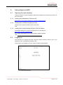
5.2
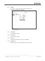
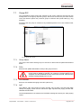
Logging on
The Username, the Password and the Company must be entered in order to log on. The
operation is then completed by pressing Login.
These values are available from your system provider or administrator.
Fig. 4: Digicom MAP homepage
Digicom MAP
User manual
Version 1.0.0 for V1.6.1
Page 14 of 49
5.2.1
Login data, administrator
User
Password
Company
5.2.2
Login data, write access
User
Password
Company
5.2.3
___________________________________
___________________________________
___________________________________
Login data, read access
User
Password
Company
5.3
___________________________________
___________________________________
___________________________________
___________________________________
___________________________________
___________________________________
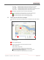
Alarms with confirmation
The data related to the alarms and confirmations is displayed via the Confirmations
menu, MAP / Alarms tab.
18.10.2012 13:13:16
Wildfire, City Park,
Fig. 5: Display of the alarms and confirmations
List of the registered alarms
List of the confirmations for the alarm selected on the left
Positive answer
Negative answer
A position exists/has been confirmed
Digicom MAP
User manual
Version 1.0.0 for V1.6.1
Page 15 of 49
Rec. pager:
Answ. pager:
Rec. server:
Answ. server:
RES.Q timestamp showing when the alarm was received
RES.Q timestamp showing when the answer was sent
Timestamp showing when the confirmation of receipt was received
Timestamp showing when the answer was received
Alarm display: Timestamp and text of the alarm selected below
Map: Forces displayed with existing position for the alarm selected below
Last measured position of the forces with positive answer
Last measured position of the forces with negative answer
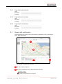
5.4
Status queries and status messages
The groups and the status data are displayed via the Confirmations menu, MAP / Status
tab.
Fig. 6: Status display
List of the registered groups
List of the current statuses for the group selected on the left
Status / Status-Time
Battery: Battery charge status
GPS Yes: GPS module is installed and is working correctly
GPS No: No GPS module installed, module is switched off or faulty
A position exists/has been confirmed
Pos.-Time: Time when the confirmed position was measured
Digicom MAP
User manual
Version 1.0.0 for V1.6.1
Page 16 of 49
Map: Forces displayed with existing position for the group selected on the left
Last measured position of the forces, position is 0 … 15 min old
Last measured position of the forces, position is 15 min … 24h old
Last measured position of the forces, position is older than 24h
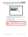
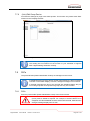
5.4.1
Exporting the status messages
Fig. 7: Export function with calendar
Export operations are executed by pressing Export.
The status list can be exported and saved if required. Data is exported in XML format in
order that it can be imported easily into other systems.
The correct data format can be validated by means of an XSD Schema file.
The XML files can also be imported into MS Excel etc.
The status messages do not have a history. Only the existing, current profiles
can therefore be viewed and saved. It is therefore not possible to find out
retrospectively when which profile was used.
Digicom MAP
User manual
Version 1.0.0 for V1.6.1
Page 17 of 49
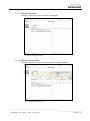
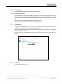
5.5
Alarm messages
18.10.2012 13:13:16
Traffic Collision w/ Entrapment 4420 E Rodeo Rd; Single vehicle rollover
Fig. 8: List of alarms (overview)
A list of previous alarms, including technical and tactical responses, can be found via the
Confirmations menu, Diagram tab.
List of the registered alarms
List of the confirmations for the alarm selected on the left
Positive answer
Negative answer
A position exists/has been confirmed
Rec. pager:
Answ. pager:
Rec. server:
Answ. server:
RES.Q timestamp showing when the alarm was received
RES.Q timestamp showing when the answer was sent
Timestamp showing when the confirmation of receipt was received
Timestamp showing when the answer was received
Alarm display: Timestamp and text of the alarm selected below
Digicom MAP
User manual
Version 1.0.0 for V1.6.1
Page 18 of 49
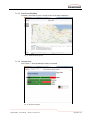
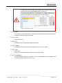
5.5.1
Exporting the alarm list
Fig. 9: Export of alarm list
Export operations are executed by pressing Export.
The alarm list can be exported and saved if required. Data is exported in XML format in
order that it can be imported easily into other systems.
The correct data format can be validated by means of an XSD Schema file.
The XML files can also be imported into MS Excel etc.
Digicom MAP
User manual
Version 1.0.0 for V1.6.1
Page 19 of 49
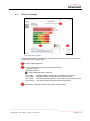
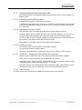
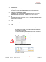
5.6
Strength message/availability report
Press Strength analysis on the Confirmations menu, Custom tab to access the alarm display with strength message.
5.6.1
Strength message
In the event of an alarm, the strength message for the defined period is shown (see Section 7.4.1)
Fig. 10: Alarm display with strength message
Alarm display: Timestamp and text of the alarm selected below
Bar chart
Top bar: Overall analysis of the current alarm
Bottom bar: Analysis of the current alarm by function group of the forces. Polyvalent forces are displayed multiple times
Legend: Matches the definition of the replies to the colors defined
Click on the Swissphone logo to close this display.
Configure the size of the bar chart by clicking on the hyperlink. A bigger text factor results in a smaller bar chart.
The settings are stored locally by using cookies. Therefore, the layout of this page
can be configured for each screen used separately.
Digicom MAP
User manual
Version 1.0.0 for V1.6.1
Page 20 of 49
5.6.2
Availability report
If no alarms are pending, the station display shows the current availability of the forces.
Fig. 11: Alarm display with availability report
Availability display
Bar chart
Top bar: Overall analysis of the current availability
Bottom bar: Analysis of availability by function group of the forces Polyvalent forces
are displayed multiple times
Legend: Matches the definition of the replies to the colors defined
Click on the Swissphone logo to close this display.
Configure the size of the bar chart by clicking on the hyperlink. A bigger text factor results in a smaller bar chart.
The settings are stored locally by using cookies. Therefore, the layout of this page
can be configured for each screen used separately.
Digicom MAP
User manual
Version 1.0.0 for V1.6.1
Page 21 of 49
6.
Master data management
Master data management can be accessed via the Master data menu.
If the strength message is currently being shown, the administration user interface is accessed by clicking on the Swissphone logo.
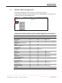
Fig. 12: Excerpt from the master data management menu
Master data management provides functions for data management in connection with the
following areas. Various different functions are available, depending on the user rights.
Function
Digicom MAP
Super user
Administrator
Write
Confirmations
Master data
Logout
Customers
Users
Additional users
Configuration
Terminals
Forces
Group RICs
RICs
Functions
Acknowledgements
Device profile
Possible Alarms
Networks
Group Structure
Import Core Data
Search
User manual
Version 1.0.0 for V1.6.1
Read
Page 22 of 49
6.1
Digicom MAP management quick reference guide
Detailed descriptions of the individual screens and input fields can be found in the Reference manual section, from page 25.
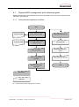
6.1.1
Recommended application workflow
Start
Customer data
Enter customer data
Define possible alarms
Customer data
Log on with admin rights
or write access
Create groups
Enter terminals
Define/prioritise functions
Enter forces/assign
terminals
Define possible alarms
Enter forces/assign
terminals
End
Mandatory
Optional
Fig. 13: Recommended Digicom MAP application workflow
Digicom MAP
User manual
Version 1.0.0 for V1.6.1
Page 23 of 49
6.1.2
Preparing personal details and alarm data
The following sections are workflow-dependent and therefore have to be processed in the
specified order.
6.1.2.1 Managing terminals (RES.Q pagers)
Fill in/edit the description, serial number and status
If the GSM number (Phone No.) is also to be entered it must be assigned a number that
is unique in the database otherwise the data record is not saved ("Number already exists"
error message)
6.1.2.2 Managing forces (device users)
Last name/first name are needed for assignment to groups (must be unique).
Terminal: RES.Q device numbers that have been created in Section 6.1.2 but have not
yet been assigned are displayed here. Select the related number and set the status.
If a force is also to receive strength messages on a terminal (pager or mobile phone) the
AdC number or the mobile number also has to be entered.
Other fields, such as Pager, Various and ForeignId are not relevant.
6.1.2.3 Creating functions
The functions produce the sub bars in the strength message.
The text and the priority must be entered.
Assign the individual functions to the forces. One force can perform several functions.
6.1.2.4 Group RICs – assigning the RICs and forces to the groups
Setting up groups: Enter the group name, RIC (7-digit) and sub address (capitals)
Other fields, such as AdC, Pattern and ForeignId have no function.
Composing groups: Click on a group, click relevant members on the Non Members table
and assign them to the Members table using the (<<) button.
Managers are also to be assigned from the Non Members table. The managers receive
strength messages via the mobile phone number entered under Manage forces.
6.1.2.5 Other functions
The other functions are described in the Reference manual section, from page 25.
Digicom MAP
User manual
Version 1.0.0 for V1.6.1
Page 24 of 49
7.
Reference manual
Fig. 14: Alarm display with strength message
The user management screen is shown by clicking on the Swissphone logo.
Depending on the user rights, some menu items may be hidden from the user account or
they may be uneditable. More information is provided in Section 6.
7.1
Creating a new customer
Creates a new customer (client). At least one customer must be entered in the system.
Fields with an asterisk (*) are mandatory.
Every customer that is created is automatically also entered as a user.
This user has administrator rights.
As managing forces, groups and terminals does not require administrator
rights, additional users should be created with restricted rights (read or
write access). More information on creating users can be found in Section
0.
Digicom MAP
User manual
Version 1.0.0 for V1.6.1
Page 25 of 49
Fig. 15: Customers screen
7.1.1
Company*
The name of the client.
Is required for the Company input box when logging on.
Four service options are available that affect the appearance of the Confirmations input
screen.
7.1.2
Service
Defines the startup screen after login.
Digicom MAP
User manual
Version 1.0.0 for V1.6.1
Page 26 of 49
7.1.2.1 BackChannelNoMap
The MAP, Alarms tab is active. A map is not displayed.
Fig. 16: Backchannel without map
7.1.2.2 BackChannelSmallMap
The MAP, Alarms tab is active. A small section of the map is displayed.
Fig. 17: Backchannel with small map
Digicom MAP
User manual
Version 1.0.0 for V1.6.1
Page 27 of 49
7.1.2.3 BackChannelBigMap
The MAP, Alarms tab is active. A large section of the map is displayed.
Fig. 18: Backchannel with big map
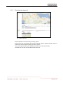
7.1.2.4 StrengthView
The Custom -> Strength Message display is activated.
Fig. 19: Strength view display
Digicom MAP
User manual
Version 1.0.0 for V1.6.1
Page 28 of 49
7.1.3
Position IMASYS Account
Can only be used if a Position IMASYS account with Swissphone Telecom AG exists.
Enter the account data.
With the Position IMASYS account, a message sent via the Info IMASYS account (see
Section 0) can be answered.
7.1.4
Position IMASYS Password
Can only be used if a Position IMASYS account with Swissphone Telecom AG exists.
Enter the password for the IMASYS Position account.
7.1.5
Info IMASYS Account
Can only be used if an Info IMASYS account with Swissphone Telecom AG exists.
Enter the account data.
With the Info IMASYS account, strength messages can also be sent to e-mail and SMS
accounts as well as to radio paging centres.
7.1.6
Info IMASYS Password
Can only be used if an Info IMASYS account with Swissphone Telecom AG exists.
Enter the password for the IMASYS Position account.
7.1.7
Locator Account
Can only be used if a Locator IMASYS account with Swissphone Telecom AG exists.
Enter the account data.
With the Locator IMASYS account, the receiver can be located via triangulation and the
approximate position can be identified.
7.1.8
Locator Password
Can only be used if an Info IMASYS account with Swissphone Telecom AG exists.
Enter the password for the IMASYS Position account.
7.1.9
Windows user
For information only.
7.1.10 Inbound Keyword/Modem
Can only be used if an IMASYS account with Swissphone Telecom AG exists.
The data received on IMASYS is assigned to the organisation on the basis of this keyword.
7.1.11 License
The number of licenses has a direct effect on the number of possible users within the organisation.
Digicom MAP
User manual
Version 1.0.0 for V1.6.1
Page 29 of 49
7.1.12 Refresh Rate
The refresh rate specifies the number of seconds after which the station display is refreshed. A very fast refresh rate places a very high load on the connected PC.
7.1.13 Position as aged
If position reporting is switched on, the reported position is deemed up-to-date within the
set time.
7.1.14 Start Position Latitude / Longitude / Zoom*
Defines the coordinates of the start location to be shown on the map; usually the customer’s locality. The zoom determines the map resolution.
The coordinates are entered with decimals.
The coordinates entered are shown in the top left-hand corner of the map
section. If the start position is to be shown approximately in the middle the
empirical values in the subsection below should be used.
The following procedure is recommended in order to identify the coordinates
of the required location
1. Open Google Maps with the web browser
2. Enter the required location
3. Select the location using the right-hand mouse button (What’s here?)
4. Read off the coordinates from the input field, accurate to four decimal
points
The additions are calculated for full HD resolution (16:9).
7.1.14.1 Large map window, 5km grid (Start Position Zoom: 10)
Addition to latitude: +0.23
Addition to longitude: -1.1
7.1.14.2 Large map window, 1km grid (Start Position Zoom: 13)
Addition to latitude: +0.025
Addition to longitude: -0.130
7.1.15 Language
Determines the Digicom MAP language. The following languages are available
English
French
Italian
German
Danish
7.1.16 Character set
Determines the POCSAG character set used
Digicom MAP
FTZ Germany
Sprintel
US ASCII
Norway Denmark
Switzerland
User manual
Version 1.0.0 for V1.6.1
Page 30 of 49
Sweden Finland
Spain
France
Britain
International
Italy
Japan
Latinamerica
Ermes
SWION France
Slovenia
7.1.17 Various
Field for own notes and comments.
7.1.18 ForeignId
Identifier (ID) from administration software used parallel to Digicom MAP.
For information only.
7.1.19 Logo
Any logo can be loaded instead of the standard RES.Q logo.
The graphic should be narrower than 200 pixels. 100 x 150 pixels is recommended.
7.1.20 Symbols
User’s own symbols can be added to the symbols available on the Acknowledgements
screen.
The symbols also appear on the map if GPS is activated on the terminal.
The graphic must be in gif format and comprise 32x32 pixel symbols. White areas are replaced by the status colour and transparent areas remain transparent.
Digicom MAP
User manual
Version 1.0.0 for V1.6.1
Page 31 of 49
7.2
Users
The user can create access to Digicom MAP for additional users.
Fields with an asterisk (*) are mandatory.
Fig. 20: Customer screen
7.2.1
Last Name*
Last name of the new user.
7.2.2
First Name
First name of the new user.
7.2.3
Function
Function held by the new user within your organisation.
7.2.4
Department
Department within your organisation that the new user works for.
Digicom MAP
User manual
Version 1.0.0 for V1.6.1
Page 32 of 49
7.2.5
User Name*
New user’s user name.
The user logs on with the user name on the log on screen. Mandatory.
7.2.6
Password*
Password that the client must enter in order to log on.
7.2.7
Message Sender Name
Can only be used if an Info IMASYS account with Swissphone Telecom AG exists.
Defines the SMS originator (sender) of the information.
A maximum of 11 characters long, alphanumeric values are also permitted. Alphanumeric
values are not transferred via the landline network; in this case purely numerical values
are to be used.
7.2.8
Language
Determines the GUI language.
7.2.9
Rights
Defines the rights of the newly created user.
7.2.9.1 Read
A user with read access can open all confirmation displays
Alarms
Status
Alarm display with strength message
Logout
7.2.9.2 Write
A user with write access can carry out the following activities in addition to the read access activities
Delete the alarm list
Trigger status queries
(can only be used in Switzerland with the Digicom MAP service from Swissphone)
Delete the status list
Furthermore, users with write access can also create, edit and delete the following entries
via master data management
Digicom MAP
Forces
Group RICs
RICs
Functions
Possible Alarms
Networks
Group Structure
User manual
Version 1.0.0 for V1.6.1
Page 33 of 49
7.2.9.3 Administrator
In addition to Write access activities, the administrator can also create, edit and delete
the following entries via master data management
Users
Configuration
Terminals
Acknowledgements
Device profile
Import Core Data
7.2.10 Status
Defines the user’s status.
7.2.10.1 Active
An active user can use the system in line with his/her user rights
7.2.10.2 Blocked
A blocked user can no longer log on to the system. However his/her master data remains
in the system. This makes it possible to block a user account for a certain period of time,
for example during an extended holiday.
7.2.11 Information Intervals
Can only be used if an Info IMASYS account with Swissphone Telecom AG exists.
Defines the time period in [s] after which the user is to be informed of the current status of
the groups.
7.2.12 Send Strength Message
Ticking the checkbox activates sending the strength message.
7.3
Additional users
Users that have already been entered can be assigned an additional client.
This function can be used when operation Digicom MAP in Command and Control Center: The CCC can add the monitored organisations by using the feature additional users.
Thus, showing all responses from the different organisations on its own screen.
Digicom MAP
User manual
Version 1.0.0 for V1.6.1
Page 34 of 49
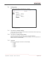
7.4
Configuration
Basic Digicom MAP display characteristics are configured.
Fig. 21: Configuration screen
7.4.1
Time span for message mapping
Tactical responses with the same alarm text that are received within this time span in [s]
are assigned to the same incident.
7.4.2
Time span for strength analysis display
Time span in [s] that the alarm message is shown on the alarm display for.
After this time span has elapsed, the theoretical availability of the forces (technical response) is shown on the alarm display.
7.4.3
Language
Determines the language of the titles on the alarm display.
Digicom MAP
English
French
Italian
German
Danish
User manual
Version 1.0.0 for V1.6.1
Page 35 of 49
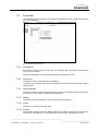
7.5
Terminals
The RES.Qs used are entered in the terminal management section. Fields with an asterisk (*) are mandatory.
Fig. 22: Manage Terminals screen
7.5.1
Description*
Each device can be given its own name. For example, this could be the organisation’s
own inventory number.
The device description is used when the terminal is assigned to a force.
7.5.2
Phone No.
Telephone number of the SIM card in the RES.Q.
The field is for information purposes only and does not affect the function of the pager or
Digicom MAP.
7.5.3
Serial Number
The serial number of the RES.Q is entered in this field. The serial number is located under the cover of the battery compartment, labelled S/N.
7.5.4
Status
The status provides information on the current status of the device.
7.5.4.1 Active
The device is active and is being used.
7.5.4.2 Inactive
The device is inactive and is not being used at the moment. This function can be used,
for example, if the RES.Q is not currently being used as it is not assigned to a force.
Digicom MAP
User manual
Version 1.0.0 for V1.6.1
Page 36 of 49
7.5.5
Various
Field for own notes and comments.
7.5.6
ForeignId
Identifier (ID) from administration software used parallel to Digicom MAP.
For information only.
7.6
Forces
All the forces that carry a RES.Q are entered in the forces management section. This
screen is also used to assign a defined terminal (RES.Q) to the forces.
Fig. 23: Manage Forces screen
7.6.1
Last Name
Last name of the force.
7.6.2
First Name
First name of the force.
7.6.3
Mobile
Mobile number that a strength message is to be sent to if the force is entered as a manager in the Group RICs settings (see Section 0). The information is sent via SMS.
In Switzerland, the number of the AdC can also be entered as an alternative.
7.6.4
Pager No.
Organisation’s internal inventory number of the pager.
Digicom MAP
User manual
Version 1.0.0 for V1.6.1
Page 37 of 49
7.6.5
Terminal
This drop down menu lists all the terminals (RES.Qs) that have been entered but have
not yet been assigned to a force. Select a device from this list to assign it to the force.
7.6.6
(Link) Go to terminal
Goes directly to the Terminals input screen. The terminal that is assigned to the currently
selected force is displayed.
7.6.7
Status
The status provides information on the current status of the force.
7.6.7.1 Active
The force is actively assigned within the organisation.
7.6.7.2 Inactive
The force is currently not active within the organisation. This function can be used, for
example, if the force is currently on holiday.
7.6.8
Various
Field for notes and comments.
7.6.9
ForeignId
Identifier (ID) from administration software used parallel to Digicom MAP.
For information only.
Digicom MAP
User manual
Version 1.0.0 for V1.6.1
Page 38 of 49
7.7
Group RIC
The organisation’s alarm groups are entered on this screen. With fire services they are
usually alarm or emergency response groups, with rescue services they are often vehicle
crews and with the police they could be groups of officers with special skills (e.g. dog
handlers).
Functions that are (can) be carried out by individual persons are to be entered under
Functions.
Fig. 24: Group RICs screen
7.7.1
Group Name
The group name shows which group is to be sent an alarm with the parameters defined
below.
7.7.2
RICs
Enter the RIC (Radio Identification Code) of the group involved.
The RIC entered must have 7 digits. If an RIC has less than 7 digits, “0”s
(zeros) must be added as required. For example, if the RIC 6000 is to be
assigned, the value 0006000 must be entered into the field. Otherwise the
strength message display will not work.
7.7.3
Sub Address
Enter the sub address belonging to the RIC (value A-D).
7.7.4
AdC
The address code, also known as paging number, has 10 digits. The first three digits
identify the paging system and the last seven digits represent the paging number that
identifies the subscriber.
The transmitted data is converted into a POCSAG message and sent by the radio paging
centre.
Digicom MAP
User manual
Version 1.0.0 for V1.6.1
Page 39 of 49
The AdC of the group in question is available from your network provider.
7.7.5
Pattern
The confirmation can be customised. The following wildcards are used
%1 = Responding
%2 = Total number of forces the alarm was sent to
%3 = Alarm message
For example, if a simple strength message is to be sent the entry will be as follows
%1 of %2 are responding.
If the alarm text is also to be sent to ensure clear assignment the entry will be as follows
%1 of %2 are responding to %3.
7.7.6
ForeignId
Identifier (ID) from administration software used parallel to Digicom MAP.
For information only.
7.7.7
Entering members
The members of the relevant groups are defined. All the forces entered are shown in the
field on the right. To add them to a group, the relevant forces must be selected in the Non
Members section and copied into the Members group using the << button.
Forces can be members of several groups.
Proceed in reverse order to remove a force from the group.
If the force is to receive strength messages it must be entered as a manager, see Section
0.
7.7.8
Entering managers
Forces, usually managers, can have strength messages sent to their mobile phone (in
Switzerland to their pager as well, via AdC).
If these forces are also to appear in the strength message (bar chart) they must be entered as members and as managers.
Forces that are to be informed but are not to be part of the strength message are only to
be entered as managers.
Confirmation is only given via the pager if the person assigned under Manager has previously been assigned a valid Mobile number on the Manage forces
screen (see Section 7.6.2).
Digicom MAP
User manual
Version 1.0.0 for V1.6.1
Page 40 of 49
7.7.9
(Link) Edit Group Device
Accesses the settings for pager user status queries. This function only works within Switzerland on the Telepage network.
Fig. 25: Manage Terminals screen
Use outside of the Telepage network (CH)
This setting has no influence on the function of your terminals or Digicom
MAP. Digital alerting still works correctly.
7.8
RICs
The personal RICs (Radio Identification Codes) are managed on this screen.
If individual persons receive alarms via their personal RIC the alarm message
is shown on the station display. However, strength messages are not shown.
If strength messages are also to be received with individual alarms the person in the group RIC must represent a group with only one member.
7.8.1
RICs
Enter the personal RIC (Radio Identification Code) of the force involved.
The RIC entered must have 7 digits. If an RIC has less than 7 digits, “0”s
(zeros) must be added as required. For example, if the RIC 6000 is to be
assigned, the value 0006000 must be entered into the field. Otherwise the
strength message display will not work.
Digicom MAP
User manual
Version 1.0.0 for V1.6.1
Page 41 of 49
7.8.2
Sub Address
Enter the sub address belonging to the RIC (value A-D).
7.8.3
Entering members
The member (force) of the relevant RIC is defined. All the forces entered are shown in the
field on the right. To assign the individual RIC to the force, the relevant force must be selected in the Non Members section and copied into the Members group using the << button.
Forces can have several individual RICs assigned to them.
Proceed in reverse order to remove a force from the group.
7.9
Functions
Functions can be assigned to the forces in the organisation. These functions are not dependent on the forces being members of defined groups.
The functions defined here are subsequently shown on the alarm display in connection
with the strength message.
Usually, the training (qualifications) and any ranks are entered as functions with fire services.
Fig. 26: Functions screen
7.9.1
Function
Defines the required function.
Digicom MAP
User manual
Version 1.0.0 for V1.6.1
Page 42 of 49
7.9.2
Priority
Determines the priority of the function. If a user has several functions, Digicom MAP attempts to assign this user the function with the highest priority that the target staffing has
not yet been achieved for.
"1" is the highest priority.
If no possible alarms are defined (see Section 7.12) the functions are not
prioritised as there is no target staffing information.
Without prioritisation, the strength message shows the sum of the available
forces in the overall analysis. However, the analysis of the function groups
shows all possible staffings, which can result in forces being named several
times.
7.9.3
Entering members
Defines the members of the relevant groups. All the forces entered are shown in the field
on the right. To add them to a group, the relevant forces must be selected in the Non
Members section and copied into the Members group using the << button.
Forces can be members of several groups.
Proceed in reverse order to remove a force from the group.
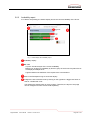
7.10
Acknowledgements
The possible acknowledgements from the RES.Qs are defined on this screen.
Fig. 27: Acknowledgements screen
Digicom MAP
User manual
Version 1.0.0 for V1.6.1
Page 43 of 49
The definition of the possible acknowledgements in Digicom MAP does
not affect the possible acknowledgements in the RES.Q.
It is imperative that indexes of the confirmations in Digicom MAP are congruent with the indexes of the confirmations in the RES.Q configuration.
Otherwise there will be incorrect information in Digicom MAP.
Fig. 28: Assignment in Digicom MAP
Fig. 29: Assignment in the PSW
7.10.1 Index
If no entries exist all indexes are -1. However they are changed to the correct values automatically when the entries are created.
7.10.2 Active
Activates the entry.
7.10.3 Text
Message text that is shown in the Digicom MAP key.
7.10.4 Symbol
Symbol that characterises the acknowledgement. Is shown on the table.
7.10.5 Color
RGB colour.
Can either be entered directly or defined using a colour palette.
7.10.6 Unavailable
Answers that have ticked this checkbox are rated not available with prioritisation of the
functions under Possible Alarms (see 7.12).
Digicom MAP
User manual
Version 1.0.0 for V1.6.1
Page 44 of 49
7.11
Device profile
The possible profiles of the RES.Qs are defined on this screen.
The strength message is displaying the theoretical available forces at the very moment.
The information regarding the availability is obtained from the active pager profile.
7.11.1 Deactivate strength analysis display
By enabling this option the strength display will be deactivated on the custom screen.
While not showing any alert messages, the display shows a white background.
7.11.2 ID
The ID defines the sequence of the profile list. The ID used in Digicom MAP has to be the
same ID as used in the PSW-Plus.
7.11.3 Text
Defines the text in the legend on the custom screen. This text must match the text used in
the PSW-Plus exactly.
7.11.4 Color
Color value in RGB.
The value can be entered directly or it can be defined by using the color palette.
The definition of the possible profiles in Digicom MAP does not affect the
possible profiles in the RES.Q.
It is imperative that indexes of the profiles in Digicom MAP are congruent
with the indexes of the profiles in the RES.Q configuration. Otherwise
there will be incorrect information in Digicom MAP.
Fig. 30: Assignment in Digicom MAP
Fig. 31: Assignment in the PSW
Digicom MAP
User manual
Version 1.0.0 for V1.6.1
Page 45 of 49
7.12
Possible Alarms
Defining possible alarms makes it possible to specify target staffing for the alarm in question.
Forces that send a positive response in the event of an alarm are assigned in accordance
with their possible function. Digicom MAP automatically attempts to staff the functions
with the highest priority first. If the target staffing of a function has been achieved the resources are assigned to priority no. 2. Therefore Digicom MAP can be used at any time to
find out whether resources sufficient for dealing with the incident are at the scene. One
can also see whether these resources have the relevant qualifications needed to deal
with the incident.
This function can also be used to set the way the alarm is shown on the display.
7.12.1 Group Name
The groups defined on the Group RICs screen are selected.
7.12.2 RICs
Shows the RICs used in the selected group.
7.12.3 Alarm Text
If the same keywords are always used in alarms (e.g. small fire, large fire or TH1, TH2
etc.) Digicom MAP can determine deployment on the basis of these texts. A target
strength can then be defined for the incident.
If a target staffing of “0” is filed for a function the status of the confirmation
is not updated on the strength message display and the status of the bar
remains Unknown status (grey). However, the total number of confirmations is still correct.
If fixed alarm keywords are not used a space can be entered. Disadvantage:
The message can then not be seen in the selection box on the left. Several
groups can nevertheless be defined and saved. The groups selection also still
works correctly.
7.12.4 Timeout
The timeout defines how long the alarm message and the confirmations are shown on the
display for. The time is specified in seconds.
For example, if an alarm is to be shown on the display for 15 minutes the timeout must be
set to 60s * 15 = 900. The unit [s] must not be entered.
Digicom MAP
User manual
Version 1.0.0 for V1.6.1
Page 46 of 49
7.12.5 Functions
The target strengths are defined by assigning the functions to the relevant alarm text.
Once a possible function has been selected it is activated using the << pushbutton. A
new field, Strength, appears. The target staffing of the selected function is to be defined
here.
If a target staffing of “0” is filed for a function the status of the confirmation
is not updated on the strength message display and the status of the bar
remains Unknown status (grey). However, the total number of confirmations is still correct.
7.13
Networks
If several redundant alarm networks are operated, this screen can be used to assign the
IDs to the networks.
The Map / Alarms tab shows which network the alarm was sent in.
This function is not used in Germany at the present time.
7.13.1 Network Name
Defines the name of the network.
7.13.2 Number
Defines the ID of the network.
7.14
Group Structure
The group structure shows all the forces entered, the RICs assigned to them and the assigned functions in a simple table.
7.14.1 Export
All the data relevant to the current customer is exported in an XML file. This data, together with the related XSD Schema file, can be imported into MS Excel 2010 and edited.
The data can therefore be imported into other tools or checked during evening duty sessions.
7.15
Import Core Data
Provides an import interface for CSV-Files with the following definition:
Datenimport (IMASYS Map/Digicom MAP)
Version;1.0.0
Serienummer;Geraetetyp;Bezeichnung;GSM_Rufnummer;OAP_Rufnummer;System
7.16
Search
Search screen for targeted searches for
Digicom MAP
Serial number
GSM number
Force number
User manual
Version 1.0.0 for V1.6.1
Page 47 of 49
Notes
Digicom MAP
User manual
Version 1.0.0 for V1.6.1
Page 48 of 49
We reserve the right to change the content of this document, in its entirety or parts thereof, without
prior notice. This document does not include product specifications and only provides brief descriptions of the issues addressed. All rights reserved. All the images and technical drawings shown in
this document are the property of SWISSPHONE Telecom AG and may only be used with our consent. Company and product names mentioned in this document may be protected by trademark,
brand or patent laws.
SWISSPHONE Telecom AG
Fälmisstrasse 21
CH-8833 Samstagern
Telephone:
Fax:
E-mail:
Web:
Digicom MAP
+41 44 786 7770
+41 44 786 7771
[email protected]
www.swissphone.com
User manual
Version 1.0.0 for V1.6.1
Page 49 of 49