1
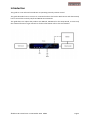
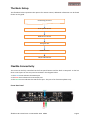
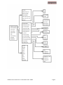
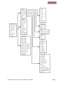
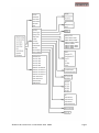
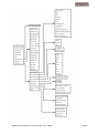
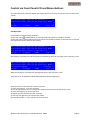
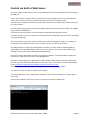
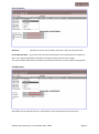
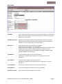
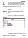
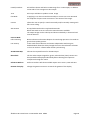
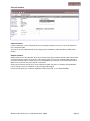
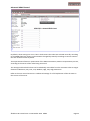
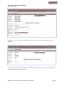
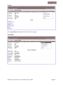
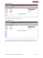
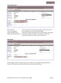
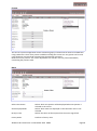
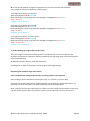
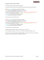
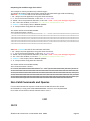
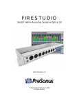
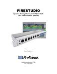
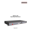
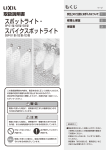
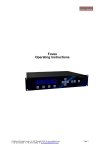
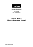
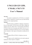
Fovea
Remote Control Guide
Version 2.1
(Includes Web Server update in firmware version 1.8.5)
Calibre UK Ltd
Cornwall House,
Cornwall Terrace
Bradford, West Yorkshire
BD8 7JS, England
Telephone +44 (0)1274 394125
Fax + 44 (0)1274 730960
Email [email protected]
Web-site www.calibreuk.com
©Calibre UK Limited issue 2.1 November 2014
Contents
Introduction
The Basic System
Flexible Connectivity
Menu Tree
Control via Front Panel Buttons
Control via Web Browser
Control via RS232
Control via TCP/IP LAN
Non Valid Commands and Queries
©Calibre UK Limited issue 2.1 November 2014 E&OE
2
3
3
4
9
10
29
32
33
Page 1
Introduction
This guide is a non-technical introduction to operating Fovea by remote control.
The guide describes how to connect to a network and use the built-in Web Server and alternatively
how to control the Fovea by TCP/IP and RS232 API commands.
This guide does not replace the product User Manual, API Manual or the Setup Guide, it covers only
the essential functions to get started. For further information refer to the User Manual.
©Calibre UK Limited issue 2.1 November 2014 E&OE
Page 2
The Basic Setup
The flowchart below represents the options for remote control, additional information can be found
further in this guide.
Connecting to Fovea
Front panel control
Web Server control
Using the API
RS232 Control
TCP/IP LAN Control
RS232 Control
Flexible Connectivity
The Fovea can be fully controlled via the front panel buttons and the built in LCD panel. It also has
three control ports on the rear panel as marked in the diagram below.
1. The BLUE arrow indicates the RS232 port
2. The RED arrow indicates the LAN TCP/IP port
3. The GREEN arrow indicates the USB service port. This port is for firmware updates only.
Fovea Rear Panel
©Calibre UK Limited issue 2.1 November 2014 E&OE
Page 3
Menu Tree
©Calibre UK Limited issue 2.1 November 2014 E&OE
Page 4
©Calibre UK Limited issue 2.1 November 2014 E&OE
Page 5
©Calibre UK Limited issue 2.1 November 2014 E&OE
Page 6
©Calibre UK Limited issue 2.1 November 2014 E&OE
Page 7
©Calibre UK Limited issue 2.1 November 2014 E&OE
Page 8
Control via Front Panel LCD and Menu Buttons
The Fovea has front panel LCD display which gives status information and access to the in-built menu
system.
IN: 1920x1080i @50.00 Hz 3G-SDI 1
OUT:1920x1080i @59.94 Hz Free Run Mode
3G-SDI 1
C-YPbPr
HDMI
Test Pat
Safe Operation
Fovea features safe operating conditions
1) The front panel Standby button must be pressed and held for 4 seconds to activate
2) The front panel channel select and menu buttons are locked by default; to activate the front panel
press the Enter button and then the i button
IN: 1920x1080i @50.00 Hz 3G-SDI 1
OUT:1920x1080i @59.94 Hz Free Run Mode
>>> Now press’i’key to unlock <<<
3G-SDI 1
C-YPbPr
HDMI
Test Pat
Attempting to operate menu when keypad is locked will prompt this message in the summary screen
IN: 1920x1080i @50.00 Hz 3G-SDI 1
OUT:1920x1080i @59.94 Hz Free Run Mode
Unlocked Keypad
Preset 1
3G-SDI 1
C-YPbPr
HDMI
Test Pat
When the keypad is un-locked this message will show in the summary screen
This feature can be disabled in Menu>Miscellaneous>Unit Configuration
All menu items can be accessed via the front panel
1) Press ‘Select/Enter’ to access the menu
2) Use the ‘up & down’ keys to navigate the required menu item to the top of the screen
3) Press ‘Select/Enter’ to access that item
4) Repeat 2) and 3) to reach the item of choice
5) Use ‘left and right’ keys to select chosen mode
6) Press ‘Menu/ESC’ or ‘Info’ to back out of menu items
©Calibre UK Limited issue 2.1 November 2014 E&OE
Page 9
Control via built-in Web Server
Fovea has a built-in Web Server which can be addressed by any current Web Browser connecting to
the LAN port.
Please note that the response time to commands sent using a Web browser varies with both the
nature of the traffic on the users network and with some versions of Web browser.
Some browsers are better than others, this has been found to be true particularly when connected
to a busy network.
Internet Explorer gives good results but preferably with Microsoft’s Smart Screen Filter turned OFF
to give the best performance
The latest versions of Chrome, Firefox and Safari respectively also give good results.
The menu system in the server mirrors the front panel menu having the extra function for uploading
a user generated logo.
Users can connect a computer directly to the LAN port with a changeover cable or via a switch or
router with normal Ethernet cables. Users can also connect via a local area network.
The TCP/IP address of Fovea can be obtained from DHCP or a Static Address, Gateway Address,
Subnet Mask and Extended Network Prefix can be set manually. To set the network address the
settings can be made in Menu>Miscellaneous>Networking
If the user changes from DHCP to Static or from Static to DHCP it is recommended to re-boot the
processor to ensure the new state is acknowledged fully.
If the user is operating Fovea’s Web Server in DHCP mode, Calibre publish a Discovery Tool which
the user can run to find Calibre processors on the user’s local area network. It can be downloaded
from http://www.calibreuk.com/software/vxl/DiscoveryTool_V1.0.exe
This tool will search the user’s network and report any Calibre processors found.
The ‘Discovery Tool’ will open a window shown below.
In this example there is just a single Fovea attached, it can be seen identified as its parent group
title of VXL
Click on the IP address of the unit you wish to access that machine’s Web server.
©Calibre UK Limited issue 2.1 November 2014 E&OE
Page 10
This is the index page when connecting to the Web server via a typical browser
Note on all pages the current source and output formats together with processing delay are
constantly monitored and displayed in the top left of the page under the menu bar.
Below are examples of how to navigate within this menu
©Calibre UK Limited issue 2.1 November 2014 E&OE
Page 11
Source Video Adjustments
From the menu bar hover or click on Source Video
There is a separate independant memory for the adjustments you make to each mode on each
source.
Refer to the User Manual and set-up guide for more detailed instructions on the use of each of the
available menu items in this section
Click on the Video Source Select drop down box to reveal the list of available sources, to select click
on the required source
Video Source Select
©Calibre UK Limited issue 2.1 November 2014 E&OE
Page 12
Source Capture
Overscan
upscales the source, the maximum overscan is 10%, the minimum is 0%.
Source Window Shift
gives horizontal and vertical adjustment of the captured active image area
Note: The range of adjustment is limited by the signal timings from the source signal.
The source window shift function should only ever be used to correct source capture discrepancies.
Clock/Position
Although automatic settings for the Analogue (VGA RGBHV) source are recommended, manual
adjustment can be made in this menu. Clock Position is for adjustment of this source only.
©Calibre UK Limited issue 2.1 November 2014 E&OE
Page 13
Aspect Ratio
AFD Mode
Fovea detects the aspect ratio of the incoming video signal. The ARC (Aspect
Ratio Conversion) settings in the Output Settings menu determine how this
information is processed.
AFD Default/Forced
determines what aspect ratio has to be assumed for further processing.
Keep Last uses whatever was seen before. If nothing was seen before the
default is 4:3 for SD modes and 16:9 for HD modes.
AFD Source
information for the source channels are as follows:
HDMI: From the AVInfoFrames (see CEA-861-D)
DVI and VGA: none available - all source formats assumed to be square pixel
CVBS/S-Video/YCbCr: WSS or CGMS-A packets, according to format.
PAL/576i uses WSS (BT.1119-2); NTSC/480i,720p,1080i use CGMS-A (CEA805/IEC 61880/EIAJ CPR-1204/etc)
Trim Width %
scales the video image in the horizontal direction
Black bars are added on left and right of the image when a shrink is
performed.
Trim Height %
scales the video image in the vertical direction.
Black bars are added on top and bottom of the image when a shrink is
performed.
Pan Left/Right %
The zoomed image can be paned in the horizontal direction
Tilt Up/Down %
The zoomed image can be tilted in the vertical direction
Reset Trim Position
Resets all trim and pan settings to zero percent.
©Calibre UK Limited issue 2.1 November 2014 E&OE
Page 14
Proc Amp
The Proc Amp provides colour correction, saturation, hue and black level adjustments separately for
each mode of each source, the memory is recalled when the source is selected or the mode changes.
Filters
Fovea has a range of image clean-up filters to help re-master poor images
©Calibre UK Limited issue 2.1 November 2014 E&OE
Page 15
CCS
CUE
ICP
3D Y/C
Luma/Chroma delay
Luma peaking gain
CTI gain
CTI coring level
TNR
TNR & MNR
MPEG NR Level
Movie Mode
Cross Chrominance Suppression filter (reduction of chroma-crawl) – SD only
Chroma Up sampling Error correction filter
Interlace Chroma Problem filter, reduces interlace errors on diagonals &
curves
Filter to reduce luminance to chrominance cross talk of composite video
signals which appears as a coarse rainbow pattern or random colours in
regions of fine details.
Adjustable delay between chroma and luma of +/- 3 pixels.
Luma transient steepening.
Chroma transient steepening.
Threshold to CTI to avoid noise being amplified
Temporal Noise Reduction (removes "electronic" noise found on broadcasts,
film material)
Selects which noise reduction filters are applied – TNR only, TNR+MNR, or
Auto for automatic image content and noise based selection of filters.
Adjusts the level of MNR (MPEG Noise Reduction) for SD signals. Not
applicable to HD formats – use TNR for removal of all types of noise from HD
formats.
When set to Auto, detects film content converted to video and applies the
inverse telecine process. When set to video, motion adaptive de-interlacing
is applied. The Film setting will apply an inverse telecine process no matter
the content. This will give great detail for film originated content video. If
the content is video this setting shows unacceptable feathering. When such
artefacts are observed the Video or Auto setting is more appropriate.
Source Features
Sharpness
a peaking filter to improve high-frequency response. Note, setting this
control too high will cause ringing or ghosting.
Detail
provides an additional level of detail enhancement beyond that provided by
the Unsharp Mask
Unsharp Mask
a powerful function which can be used to greatly improve detail definition
and clarity without causing image ringing or ghosting. It improves both
horizontal and vertical detail. Correct setting of the Unsharp Mask filter can
make SD signals look virtually indistinguishable from true HD.
©Calibre UK Limited issue 2.1 November 2014 E&OE
Page 16
Output Video
Refer to the user manual for a full explanation of the functions in this menu
Output Format
The unit can be set to operate at a fixed output format. The following output formats can be chosen:
480i59.94, 576i50, 720p50, 720p59.94, 720p60, 1080i50, 1080i59.94, 1080i60, 1080sf23.98,
1080sf24, 1080sf25, 1080p23.98, 1080p24, 1080p25, 1080p29.97, 1080p30, 1080p50, 1080p59.94,
1080p60
Lock Mode
Free run
Frame synchronize
Auto Format
Genlock
uses internal synch clocks set under Output Format.
uses the genlock signal. The phase can be controlled allowing adjustment for
a desired latency.
chooses the mode provided on the genlock input regardless of the setting
under Output Format.
status is shown via the front panel status indication on the right-hand side of
the screen, provided it has been enabled on the menu.
Reference Source
The source for the frame synchronisation signal can be either an analogue bi- or tri-level signal or
derived from an SDI signal. Note: this needs to be set to the genlock input you are using.
Reference Offset
Vertical
Horizontal
ARC Mode
Bypass
Crop
Anamorphic
Increase the latency in multiples of lines.
Increase the latency in multiples of pixels.
will scale the image to full screen.
25% makes a 4:3 fit a 16:9 by chopping off top and bottom; or makes a 16:9
fit a 4:3 by chopping off (25% off) left and right.
is for 4:3 SD outputs only, it linearly compresses a 16:9 image into 4:3
without cropping or added bars.
©Calibre UK Limited issue 2.1 November 2014 E&OE
Page 17
Panels/Letterbox
will add bars above and below a 16:9 image for a 4:3 SD output, or add bars
at the sides of a 4:3 image on a 16:9 output.
14:9
will crop or add bars to produce a 14:9 image
Flex Wide
is applying a non-linear stretch horizontally to convert a 4:3 into 16:9 with
the emphasis of aspect ratio conversion in the centre of the image.
Custom
allows the user to specify a zoom horizontally and/or vertically starting with
full screen scaling.
ARC Custom
H Crop/Side Panels and V Crop/Letterbox Panels
When ARC mode is set to Custom this menu becomes available.
The output image can be scaled up and down individually in horizontal and
vertical direction.
Process Mode
Full Processing
Low Latency
Noise reduction and motion-adaptive de-interlacing operate in this mode to
give the best quality picture.
In this mode noise reduction and motion-adaptive de-interlacing are
disabled which allows the delay through the unit to be reduced to 3 frames
in free run mode or 2 frames when frame synchronising.
3G-SDI Data Map
Choose the required format for the SDI output
Blue Check
The live video output image blue, green, red and white (luma) content can
be separated and displayed individually when selecting the respective
component through this menu.
Safe Area Markers
Safe area markers will show available aspect ratios are 4:3, 14:9 and 16:9.
Gamma of Display
Change the gamma correction to match the gamma of the display.
©Calibre UK Limited issue 2.1 November 2014 E&OE
Page 18
Audio
Refer to the user manual for a full description of each item in this menu
The audio streams from the AES, HDMI and SDI source can be routed or muted here
Choose between channels 1 to 8 or 9 to 16 in group 1 or 2
Audio Delay is automatically set to compensate for the latency through the unit.
The Audio Delay adjustment allows fine calibration of the audio delay in steps of approximately 1mS,
to advance or retard the audio so as to compensate for further delays in your display device or your
audio system.
©Calibre UK Limited issue 2.1 November 2014 E&OE
Page 19
MEMC/FRC Adjustments
From the menu bar hover over or click on MEMC/FRC
Click on MEMC Configuration
FRC Level
Click on the FRC level drop down box
A range of customised settings arranged under names intended to indicate typical applications are
available – note Drop/Repeat turns off the Motion Compensation
©Calibre UK Limited issue 2.1 November 2014 E&OE
Page 20
MEMC Demo Mode
The user can choose to apply MEMC correction to one portion of the screen whilst the rest of the
screen is not processed. This is primarily for demonstration but can also be a useful tool when
analysing picture artefacts
Exclusion Zone
In this menu section an area of the screen can be excluded from the Motion Compensation for
applications such as ticker tape data at the bottom of the screen.
©Calibre UK Limited issue 2.1 November 2014 E&OE
Page 21
Film and Cadence
Cadence Detect
Cadence Detection can be switched off (none accepted), limited to 3:2/2:2 or set to full detection
(any accepted) mode.
This can be set up independently for the two groups of 23.98Hz to 30Hz and 50Hz to 60Hz video
modes.
Output Cadence
Output Cadence can be switched off or the incoming video signal cadence will be used to determine
an output cadence. When set to Auto 2:2/3:2 filmic stutter of 3:2 or 2:2 or 23.98/24Hz material is
preserved by applying a 2:2 (50Hz o/p) or 3:2 (50.94/60Hz o/p) cadence to the converted material.
When set to Auto 2:2 only 2:2 material is preserved.
Setting up Forced 2:2/3:2 will force a 2:2 cadence for 50Hz o/p and a 3:2 cadence for 59.94/60Hz
o/p no matter if there is a cadence on the incoming video signal.
Forced 2:2 will apply a 2:2 cadence regardless of the o/p mode, i.e. for 50/50.94/60Hz.
©Calibre UK Limited issue 2.1 November 2014 E&OE
Page 22
Advanced MEMC Control
By default, these settings are set to ‘Auto’ which means the values are selected internally according
to the MEMC/FRC level setting, and sometimes changed dynamically according to various statistics
that are measured frame by frame.
These parameters allow user optimisation of the Motion Estimation, Motion Compensation process,
according to the nature of the video being converted.
The settings and threshold values can be individually overridden from the automatic value to stages
denoted as Minimum, Very Low, Low, Medium, High, Very High, Maximum.
Refer to the user manual section 3.5.2 Advanced settings for a full explanation of the the items in
this section of the menu.
©Calibre UK Limited issue 2.1 November 2014 E&OE
Page 23
Time Code and Closed Captioning
Click on Time Code
In this section of the menu all the settings for free run or source referenced time code can be
accessed
Closed caption information can be detected and included in the output data. For a full explanation
please refer to 4.11 of the user manual
©Calibre UK Limited issue 2.1 November 2014 E&OE
Page 24
System
Load the top menu of System by clicking on System in the menu bar
Note ‘Logo Upload’ is the bottom item on the left of the page.
Information
This is a list of information, no adjustments can be made in this menu
©Calibre UK Limited issue 2.1 November 2014 E&OE
Page 25
Chanel Logo Overlay
Channel Logo Overlay logo can be overlaid on the video image. Logo location can be set to be in the
top left, top right, bottom left or bottom right corner.
Source Channel Config
The 4 source select buttons on the front of the unit can be associated with the user’s choice of
source. Select the source channel form the list on the lower left and then choose the ‘source select
key’.
©Calibre UK Limited issue 2.1 November 2014 E&OE
Page 26
Unit Configuration
Menu Timeout
Front Panel Backlight
Power Inlet Monitoring
Enable Auto Keypad Lockout
sets the time for the front panel to go back to the top level menu
sets the brightness of the front panel backlight
determines whether the power inlets are monitored for dual supply
By default the keypad is locked. It can always be unlocked by
pressing the sequence of Enter and Information keys.
Networking
Networking(TCP/IP) The IP address type (static or DHCP), static IP address, default gateway IP
address, subnet mask and extended network prefix can all be entered here.
©Calibre UK Limited issue 2.1 November 2014 E&OE
Page 27
Presets
The current system configuration can be stored using Copy to Preset and can then be recalled later
using Load Preset. There are 4 presets available including the current one. Any preset can be reset
using the Reset command and renamed using the Rename command.
Note the current preset is ‘live’ menu adjustments are stored in the live preset immediately
overwriting the previous state.
More
Select Test Pattern
No Sync Color
Selects which test pattern will be displayed when test pattern is
selected as the source
Selects which items are displayed on the LCD when menu is not
selected
Selects the colour of the output when the source signal fails
Factory Reset
Performs a factory reset
Status Display Mode
©Calibre UK Limited issue 2.1 November 2014 E&OE
Page 28
Control via API
The API manual is available to download from:http://www.calibreuk.com/documents/vxl/VXL%20API%20Protocol_v1.40%20Generic.pdf
Please refer to this manual for detailed description of control parameters and for lists of codes for
each type of action required for remote control using either the RS232 port or the TCP/IP LAN port
Control via RS232 Remote Control Port
a. Here is an example of how to use the API control information:1. Open HyperTerminal or similar application on your computer
Set the parameters for the serial port to:baud rate - 9600
parity - none
data bits - 8
stop bits - 1
2. Send an identify request string to see if the user can talk to the box. Send 16x A, i.e.
AAAAAAAAAAAAAAAA. If successful communication is established the answer VXL500HD is
returned.
3. This example is used to provide easily visible changes:To change the active source to 3G-SDI 2 send the following string: APCAAA2AEAAAAABA
This string is made up of the following:Please note that items ii. Iii. and iv. are listed in the API manual.
i. AP - always start the application string with these characters
ii. C - this is the function identifier, in this case:- C = set a value)
iii. AAA2 – this is the parameter identifier, in this case:- AAA2 = select source)
iv. AE – this is the attribute, in this case:- AE = change it live
(Change it live means – change source but don´t store the change in the EEPROM. If the user wants
Fovea to remember this source then use the attribute AF instead)
v. AAAAAB - is the value in BASE64 alphabet
AAAAAA = 3G-SDI 1, AAAAAB = 3G-SDI 2, AAAAAC = Component YPbPr, AAAAAD = CVBS 1,
AAAAAE = CVBS 2, AAAAAF = S-Video, AAAAAG = DVI, AAAAAH = HDMI, AAAAAI = Analog,
AAAAAJ = Test Pattern.
In this case AAAAAB = change to source 3G-SDI 2
vi. A - always end the string with this character
©Calibre UK Limited issue 2.1 November 2014 E&OE
Page 29
b. In this second example, change the assigned source to the front panel source buttons
This example is used to provide easily visible changes:To change source button 1 to 3G-SDI 1
Send the string APCAABaAEAAAAABA
Note that the parts of the string that have changed are highlighted in red or blue
AABa = 3G-SDI 1
AAAAAB = Source Button 1
To change source button 2 to C-YPbPr
Send the string APCAABVAEAAAAACA
Note that the parts of the string that have changed are highlighted in red or blue
AABV = C-YPbPr
AAAACB = Source Button 2
To change source button 4 to Test Pattern
Send the string APCAABXAEAAAAAEA
Note that the parts of the string that have changed are highlighted in red or blue
AABX = Test Pattern
AAAAAE = Source Button 4
c. Understanding the range of data of the ‘Value’
The value ranges are not listed for each function, instead the user can send a request for the
maximum and minimum valid values thereby establishing the operating range of the value segment
of the command string.
An ON/OFF command will only have two valid values
A setting such as audio delay will have a wide range of valid range settings.
Requesting the available range of the ‘Value’
Care is needed when making requests and in receiving replies to such requests
After sending a request and before receiving the reply, it is necessary to have a delay.
Section 2.3 of the API manual shows a table providing a list of delays for specific parameters. For
parameters that are not listed in the table the delay should be 10 milliseconds.
Note:- Failing to observe this requirement for a delay can cause serious adverse effects such as lockups and data corruption which may require a power cycle and possibly a factory reset to clear.
©Calibre UK Limited issue 2.1 November 2014 E&OE
Page 30
Example value range requests and replies:This example is used to provide easily visible changes:To request the range of valid values when setting the LCD panel back light send the following:APBAAC8ACAAAAAAA to ask for the minimum valid value
i. AP - always start the application string with these characters
ii. B - this is the function identifier, in this case:- B = Get a value
iii. AAC8 – this is the parameter identifier, in this case:- AAC8 = Front panel backlight brightness
iv. AC – this is the attribute, in this case:- AC = Minimum valid parameter value
v. AAAAAA - is the enquiry value in BASE64 alphabet
vi. A - always end the string with this character
The answer will be returned OK:AAAAAA
APBAAC8ADAAAAAAA to ask for the maximum valid value
i. AP - always start the application string with these characters
ii. B - this is the function identifier, in this case:- B = Get a value
iii. AAC8 – this is the parameter identifier, in this case:- AAC8 = Front panel backlight brightness
iv. AC – this is the attribute, in this case:- AD = Maximum valid parameter value
v. AAAAAA - is the enquiry value in BASE64 alphabet
vi. A - always end the string with this character
The answer will be returned OK:AAAAD/
The Base64 number system is outlined in the API manual in section 3.4.1
So the valid range of settings for this function are between AAAAAA and AAAAD/ (0 – 255)
If the user now sends the command APCAAC8AEAAAABBA, as described in the previous examples in
this guide, the LCD window will be set to brightness 65 of 255.
©Calibre UK Limited issue 2.1 November 2014 E&OE
Page 31
Control via TCP/IP LAN Remote Control Port
Connect to the LAN port.
Users can connect directly to the LAN port with a changeover cable or via a switch or router with
normal Ethernet cables.
Users can also connect via a local area network.
The TCP/IP address of the Fovea can be obtained from a DHCP server or set manually in
Menu>Miscellaneous>Networking
[IP Address Type
Use Static]
Static IP Address
169.254.0.3
Default Gateway IP Ad192.168.254.250
Subnet Mask
255.255.255.0 ↓
If the user changes from DHCP to Static or from Static to DHCP it is recommended to re-boot the
processor to ensure the new state is acknowledged fully.
Note:- port number is 30001
Examples of code
The code structure is the same as in the RS232 examples given in the previous section of this guide.
Send an identify request string to see if the user can talk to the box. Send 16x A, i.e.
AAAAAAAAAAAAAAAA. If successful communication is established the answer VXL500HD is
returned.
The answer is in the form of a much longer string than for RS232, as described in the API manual – it
looks like this:VXL500HD¥¥Z¥Z¥ZZ¥¥Z¥Z¥ZZ¥¥Z¥Z¥ZZ¥¥Zª²øª¬°Z¥ZKÜ(¥Z¥ZZ¥¥Z¥Z¥ZZ¥¥Z¥Z¥[Z¥¥Z¥Z¥Z[¥¥Z¥Z¤ZZ
¥¥Z¥Z¥ZZ¥¥Z¥Z¥ZZ¥¥Z¥Z¥ZZ¥¥Z¥Z¥ZZ¥¥Z¥Z¥ZZ¥¥Z¥Z¥ZÚ¥¥Z¥Z¥ZZ¥¥Z¥Z¥ZZ¥¥Z¥Z¥ZZ¥¥Z¥Z¥ZZ¥¥Z
¥Z¥ZZ¥µZ¥Z¥ZZ¥¥Z¥Z¥ZZ¥¥Z¥Z¥ZZ¥¥Z¥Z¥ZZ¥¥Z¥Z¥ZZ¥¥Z¥Z¥ZZ¥¥Z¥Z¥ZZ¥¥Z¥Z¥ZZ¥¥Z¥ZµZZ¥¥[¥Z¥Z
Z¥¥Z¥Z¥ZZ¥¥Z¥Z¥ZZ¥¥Z¥Z¥ZZ¥¥Z¥Z¥ZZ¥¥Z¥Z¥ZZ¥¥Ú¥Z¥ZZ¥¥Z¥Z¥ZZ¥¥Z¥Z¥ZZ¥¥Z¥Z¥ZJ¥¥ZµZ¥ZZ¥¥Z
¥Z¥ZZ¥¥Z¥Z¥ZZ¥¥Z¥Z¥ZZ¥¥Z¥Z¥ZZ¥¥Z¥Z¥ZZ¥µZ¥Z¥ZZ¥¤Z¥Z¥ZZ¥¥Z¥Z¥ZZ¥¥Z¥Z¥ZZ¥¥Z¥Z¥ZZ¥¥Z¥[¥Z
Z¥¥Z¥Z¥ZZ¥¥Z¥Z¥ZZ§¥Z¥Z¥ZZ¥¥Z¥Z¥ZZ¥¥Z¥Z¥ZZ¥¥Z¥Z¥ZZ¥¥Z¥Z¥ZZ¥¥Z¥Z¥ZZ¥¥Z¥Z¥ZZ
Understanding the range of data of the ‘Value’
The value ranges are not listed for each function, instead the user can send a request for the
maximum and minimum valid values thereby establishing the operating range of the value segment
of the command string.
An ON/OFF command will only have two valid values
A setting such as audio delay will have a wide range of valid range settings.
©Calibre UK Limited issue 2.1 November 2014 E&OE
Page 32
Requesting the available range of the ‘Value’
This example is used to provide easily visible changes:To request the range of valid values when setting the LCD panel back light send the following
APBAAC8ACAAAAAAA to ask for the minimum valid value
i. AP - always start the application string with these characters
ii. B - this is the function identifier, in this case:- B = Get a value
iii. AAC8 – this is the parameter identifier, in this case:- AAC8 = Front panel backlight brightness
iv. AC – this is the attribute, in this case:- AC = Minimum valid parameter value
v. AAAAAA - is the enquiry value in BASE64 alphabet
vi. A - always end the string with this character
The answer will be returned OK:AAAAAA
This is how the answer is shown
OK:AAAAAA¥Z¥Z¥ZZ¥¥Z¥Z¥ZZ¥¥Z¥Z¥ZZ¥¥Zª²øª¬°Z¥ZKÜ(¥Z¥ZZ¥¥Z¥Z¥ZZ¥¥Z¥Z¥[Z¥¥Z¥Z¥Z
[¥¥Z¥Z¤ZZ¥¥Z¥Z¥ZZ¥¥Z¥Z¥ZZ¥¥Z¥Z¥ZZ¥¥Z¥Z¥ZZ¥¥Z¥Z¥ZZ¥¥Z¥Z¥ZÚ¥¥Z¥Z¥ZZ¥¥Z¥Z¥ZZ¥¥
Z¥Z¥ZZ¥¥Z¥Z¥ZZ¥¥Z¥Z¥ZZ¥µZ¥Z¥ZZ¥¥Z¥Z¥ZZ¥¥Z¥Z¥ZZ¥¥Z¥Z¥ZZ¥¥Z¥Z¥ZZ¥¥Z¥Z¥ZZ¥¥Z¥Z
¥ZZ¥¥Z¥Z¥ZZ¥¥Z¥ZµZZ¥¥[¥Z¥ZZ¥¥Z¥Z¥ZZ¥¥Z¥Z¥ZZ¥¥Z¥Z¥ZZ¥¥Z¥Z¥ZZ¥¥Z¥Z¥ZZ¥¥Ú¥Z¥ZZ
¥¥Z¥Z¥ZZ¥¥Z¥Z¥ZZ¥¥Z¥Z¥ZJ¥¥ZµZ¥ZZ¥¥Z¥Z¥ZZ¥¥Z¥Z¥ZZ¥¥Z¥Z¥ZZ¥¥Z¥Z¥ZZ¥¥Z¥Z¥ZZ¥µZ
¥Z¥ZZ¥¤Z¥Z¥ZZ¥¥Z¥Z¥ZZ¥¥Z¥Z¥ZZ¥¥Z¥Z¥ZZ¥¥Z¥[¥ZZ¥¥Z¥Z¥ZZ¥¥Z¥Z¥ZZ§¥Z¥Z¥ZZ¥¥Z¥Z¥
ZZ¥¥Z¥Z¥ZZ¥¥Z¥Z¥ZZ¥¥Z¥Z¥ZZ¥¥Z¥Z¥ZZ¥¥Z¥Z¥ZZ¥¥Z
APBAAC8ADAAAAAAA to ask for the minimum valid value
i. AP - always start the application string with these characters
ii. B - this is the function identifier, in this case:- B = Get a value
iii. AAC8 – this is the parameter identifier, in this case:- AAC8 = Front panel backlight brightness
iv. AC – this is the attribute, in this case:- AD = Maximum valid parameter value
v. AAAAAA - is the enquiry value in BASE64 alphabet
vi. A - always end the string with this character
The answer will be returned OK:AAAAD/
This is how the answer is shown:OK:AAAAD/¥Z¥Z¥ZZ¥¥Z¥Z¥ZZ¥¥Z¥Z¥ZZ¥¥Zª²øª¬°Z¥ZKÜ(¥Z¥ZZ¥¥Z¥Z¥ZZ¥¥Z¥Z¥[Z¥¥Z¥Z¥Z[¥¥Z¥Z¤ZZ
¥¥Z¥Z¥ZZ¥¥Z¥Z¥ZZ¥¥Z¥Z¥ZZ¥¥Z¥Z¥ZZ¥¥Z¥Z¥ZZ¥¥Z¥Z¥ZÚ¥¥Z¥Z¥ZZ¥¥Z¥Z¥ZZ¥¥Z¥Z¥ZZ¥¥Z¥Z¥ZZ¥¥Z
¥Z¥ZZ¥µZ¥Z¥ZZ¥¥Z¥Z¥ZZ¥¥Z¥Z¥ZZ¥¥Z¥Z¥ZZ¥¥Z¥Z¥ZZ¥¥Z¥Z¥ZZ¥¥Z¥Z¥ZZ¥¥Z¥Z¥ZZ¥¥Z¥ZµZZ¥¥[¥Z¥Z
Z¥¥Z¥Z¥ZZ¥¥Z¥Z¥ZZ¥¥Z¥Z¥ZZ¥¥Z¥Z¥ZZ¥¥Z¥Z¥ZZ¥¥Ú¥Z¥ZZ¥¥Z¥Z¥ZZ¥¥Z¥Z¥ZZ¥¥Z¥Z¥ZJ¥¥ZµZ¥ZZ¥¥Z
¥Z¥ZZ¥¥Z¥Z¥ZZ¥¥Z¥Z¥ZZ¥¥Z¥Z¥ZZ¥¥Z¥Z¥ZZ¥µZ¥Z¥ZZ¥¤Z¥Z¥ZZ¥¥Z¥Z¥ZZ¥¥Z¥Z¥ZZ¥¥Z¥Z¥ZZ¥¥Z¥[¥Z
Z¥¥Z¥Z¥ZZ¥¥Z¥Z¥ZZ§¥Z¥Z¥ZZ¥¥Z¥Z¥ZZ¥¥Z¥Z¥ZZ¥¥Z¥Z¥ZZ¥¥Z¥Z¥ZZ¥¥Z¥Z¥ZZ¥¥Z¥Z¥ZZ¥¥Z
Non Valid Commands and Queries
If a non valid command or request is made the Fovea HD will return the answer
ER: followed by a string such as ER:AAAAADAAAAAA = Function is not implemented
Error codes can be found in the API manual section 3.2.2.4
END
E&OE
©Calibre UK Limited issue 2.1 November 2014 E&OE
Page 33