1
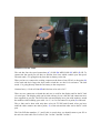
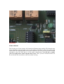
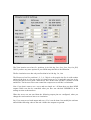
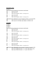
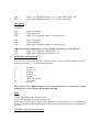
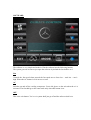
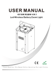
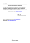
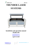
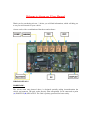
Welcome to Aircon ver 2 User Manual.
Thank you for purchasing Aircon - 2 below you will find information, which will help you
to set your Aircon unit for your vehicle.
Aircon works with a combination of hardware and software.
WIRING DETAILS
HARDWARE:
The Aircon main unit pictured above is designed specially taking inconsideration the
vehicle environment. The unit works directly from unregulated 12vdc connected at point
(A) POSITIVE (B) NEGATIVE. The Unit is polarity protected for better safety.
POWER CONNECTION
The unit has four fan speed connections (C) LOW (D) MED LOW (E) MED (F) HI. To
connect the fan speed you will have to find the four wires which controls your fan speed.
The unit sends +12v going directly from the car battery to the fan.
Then you have to connect the cooling compressor the heart of any HVAC to the point (G)
of the unit and don’t forget the dyer bottle switch the see above for reference. The unit
sends +12v going directly from the car battery to the comperssor
Connect heavy +12vdc to Point (H) this line has to be active 24/7.
There are two connectors on board the unit one is used for the display and for the PC link
via serial port. The display cable can be built with any 9 core cable the end connectors have
been supplied in your kit. The PCB of the unit and display have pins with numbers, match
the numbers while building your cable 1 to 1, 2 to 2 so on connect it to point (I) of the unit.
The pc link can be done with only three wires for TX RX and Ground. After you have
made the cable connect one end to point ( J ) of the unit and the other end to the PC serial
port.
The Unit PCB has numbers 2, 3 and 5 this is exactly how you should connect your PC to
the unit via serial cable. Pin 2 to Pin 2, Pin 3 to Pin 3 and Pin 5 to Pin 5
The POINT ( K ) is an aux point used for rear wind screen defrost. This point has +12v
when on from the software. So depending on your vehicle you will have to set it up.
EXTERNAL
INTERNAL
TEMP SENSOR
The Unit has two Temp sensors for External and Internal temp reading. The Internal temp
sensor should be place anywhere close to the intake of the blower unit so the cabin temp
can be read. The external sensor can be placed anywhere you feel you can read the external
atmosphere temp. DO NOT place it in the engine compartment. You will have to make
your own temp sensor cable with just three wires. Once you have tested the LM35 on
the unit board. Do not make the cable more than 2m long.
SERVO:
There are three servo connection point ( L ) , ( M ), ( N ) any 5 volt servo can be used with
this unit.
SER1 = CIRCULATION
SER2 = VENT MODE
SER3 = HEAT
CENTER PIN IS +5vDC
All servos can move 0 ~ 180 deg. You will have to find the flaps where you want to install
these servos. All cars I have seen till now have got some kind of flap, which controls the
airflow for the vent locations, re circulation and for the heat.
Once you have placed your servo check for the movement move the servo by hand and see
if it’s doing its work
Once you have accomplished this open the setting program in the software section and
move each servo to its desired position and save the position so the software know which
servo position is for what purpose.
SETTING
The Vent location servo has five positions in its 180 deg. face, face_feet, feet, feet_WS,
WS. If you have any more options in your OEM setup then this is the limitation.
The Re circulation servo has only two Position in its 180 deg . In , Out
The Heat servo has five positions 1, 2, 3, 4, 5 this is so for people who live in cold weather
and need the heat so you can set the ac cutoff temp say to 24 and add some hot air by
moving the heat servo to point 2 then the air flow on the vents will have a mixture of cold
and hot air. The heat servo does not control the compressor cut off this is a limitation.
Now if you don’t want to use a servo and use simple on / off then there are these NINE
outputs which can also be controlled when you have not checked USESERVO in the
settings section as shown above.
When the servos are not used then the following output pins are configured, when you
change the vent location or heat or re circulation.
Say if you want to use both output and servo, Yes it can be done. Just modify the software
and send the following codes to the unit. All the nine outputs are ground.
Recirculation output
OUTPUT 1
OUTPUT 9
When the following command is sent the unit works like this
D1P =
output 9 goes high
D0P =
output 9 goes low
D2P =
output 9 goes high then within ½ second goes low
E1P
E0P
E2P
=
=
=
output 1 goes high
output 1 goes low
output 1 goes high then within ½ second goes low
AIRCON uses this combination it can be changed if you know to work with VB
D3P =
output 9 goes low and output 1 goes high (re circulation is on)
D4P =
output 1 goes low and output 9 goes high (re circulation is off)
Vent output
OUTPUT 2
OUTPUT 3
OUTPUT 4
OUTPUT 5
OUTPUT 6
When the following command is sent the unit works like this
F1P =
output 2 goes high
F0P =
output 2 goes low
F2P =
output 2 goes high then within ½ second goes low
G1P
G0P
G2P
=
=
=
output 3 goes high
output 3 goes low
output 3 goes high then within ½ second goes low
H1P
H0P
H2P
I1P
I0P
I2P
=
=
=
=
=
=
output 4 goes high
output 4 goes low
output 4 goes high then within ½ second goes low
output 5 goes high
output 5 goes low
output 5 goes high then within ½ second goes low
J1P
J0P
J2P
=
=
=
output 6 goes high
output 6 goes low
output 6 goes high then within ½ second goes low
AIRCON uses this combination it can be changed if you know to work with VB
F3P =
output 6 goes HIGH and output 2, 3, 4, 5 goes LOW (FACE)
F4P =
output 5 goes HIGH and output 2, 3, 4, 6 goes LOW (FACE_FEET)
F5P =
output 4 goes HIGH and output 2, 3, 5, 6 goes LOW (FEET)
F6P
F7P
=
=
output 3 goes HIGH and output 2, 4, 5, 6 goes LOW (FEET_WS)
output 2 goes HIGH and output 3, 4, 5, 6 goes LOW (WS)
Heat output
OUTPUT 7
OUTPUT 8
K1P
K0P
K2P
=
=
=
output 7 goes high
output 7 goes low
output 7 goes high then within ½ second goes low
L1P
L0P
L2P
=
=
=
output 8 goes high
output 8 goes low
output 8 goes high then within ½ second goes low
AIRCON uses this combination it can be changed if you know to work with VB
K2P =
output 7 goes HIGH then LOW after ½ sec
L2P =
output 8 goes HIGH then LOW after ½ sec.
REMOTE CONTROLLER
The unit also works with any RC5 protocol remote control. Like the Phillips and JVC
remotes the numbers 1 ~ 8 controls the following.
1
2
3
4
5
6
7
8
=
=
=
=
=
=
=
=
Fan Mode
Aux on / off
Ext temp
Temp up
Temp dn
Check cutoff temp
Comp on/off
On / off
The remote is not supplied with the unit. I am working on one when ready will be
shipped free of cost to all who has bought the kit. ☺
LED
Yellow LED indicates the unit has power.
Green LED indicates the cooling process is on.
Red LED is for the remote feature when blinks mean wrong signal is received and when
the led is on and not blinking during press of a button on the remote indicates right signal is
received.
Well that’s it for the hardware part.
SOFTWARE:
The software is very simple and made in Vb6 the software has the following buttons
The system goes on as soon as you open the software by default the fan shall be on 1.
Fan
Controls the fan speed when pressed the fan speed moves from low ~ med low ~ med ~
high. When the AC button is on it moves to Auto.
AC
Switches on and off the cooling compressor. Green led glows on the unit when the a/c is
activated. The fan shall go to the Auto mode only when this button is on.
OFF
This is the exit button. You’re a/c system shall just go off and the software shall exit.
EXT
Pressing this button will display the external temp on the LED display for 2sec and will go
back to displaying the internal temp.
RECIRCULATION
Controls the re circulation servo or on / off.
MODE
Controls the vent positions each press shall change the position and display the current
position. IMP when pressing the mode button be gentle give the servo time to complete its
movement before moving it to another position. Or if you have chosen not to use the servo
then it will do the on/off thing.
REAR DEFROST
Simple on and off
HEAT DOWN
Shall move the heat servo to one step lower from the current position. If already in the
lowest position then nothing happens. Or if you have chosen not to use the servo then it
will do the on/off thing.
HEAT UP
Shall move the heat servo to one step higher from the current position. If already in the
highest position then nothing happens. Or if you have chosen not to use the servo then it
will do the on/off thing.
TEMP DOWN
Changes the preset compressor cutoff temp when pressed the display will show the preset
temp and shall move one deg lower min 16deg.
TEMP UP
Changes the preset compressor cutoff temp when pressed the display will show the preset
temp and shall move one deg higher max 30deg.
The unit once set to cutoff at a certain temp will cool the vehicle to one degree less
than that and cutoff the compressor then when the temp goes up one deg will start the
compressor again.
INSTALLATION PROCEDURE
After you have connected the unit to power and serial as shown in Figure 1. When the unit
receives power on the points A and B it shall power up and power down immediately.
Open the Aircon software unit will power on automatically and the display will show the
current temp read on the internal temp if your cables are done fine.
Your fan shall be on F1 by default.
That’s it your all set enjoy you new toy ☺
If you have any further clarifications or need advice feel free to contact me
[email protected] I shall answer A.S.A.P or you can catch me on MSN messenger.
Thankyou.
Mastero