1
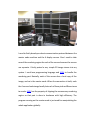
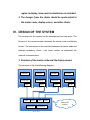
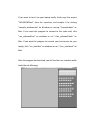
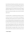
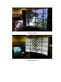
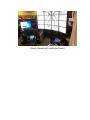
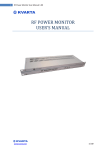
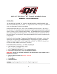
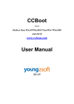
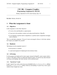
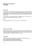
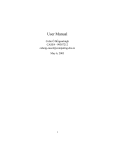
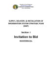
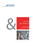
Brown University
Department of Computer Science
Laboratory for Engineering Man-Machine System (LEMS)
REPORT
OF THE
READING & RESEARCH
Supervisor: Gabriel Taubin
Author: Yan Li
February 2013 - December 2013
I.
INTRODUCTION
I have worked under the supervision of Prof. Gabriel Taubin since
February on a project about videowall. The project involves the
knowledge
of
computer
graphics,
computer
network
and
synchronization. We thought that we could use the videowall in LEMS
to develop some innovative applications and I started from there. The
videowall is basically a 4x4 monitor matrix of 16 monitors. Since we
have 16 monitors, it means that we have much more pixels to display.
Therefore we came up with an idea: using the videowall to display
something high-resolution like very large image or very fine mesh. The
4x4 monitors are driven by 4 computers and we treat the 4 computers
as display servers. In addition to the 4 servers, we also have a master
node machine which is just in front of the 4 servers. We use that
master node to control the behavior of the 4 servers. So in this
structure, the master node is like a client.
Here is a snapshot of the above structure:
I need to firstly develop a robust communication protocol between the
master node machine and the 4 display servers. Also I need to take
care of the rendering region for each of the servers because the servers
are separate. I firstly ported a very simple 2D image viewer into my
system. I used Java programming language and JOGL to handle the
rendering part. Basically, each of the servers has a local copy of the
image, and so is the master node. When the connection is built, each
the 4 servers loads image locally but each of them picks a different area
to render. JOGL has the property of clipping the unnecessary rendering
region so that part is done in hardware with high efficiency. The
program running on the master node is just used for manipulating the
whole application globally.
I then used this idea and developed a 3D mesh viewer using my system.
It was more complicated because in a 3D scene, a camera is used to
capture the image. However the idea was just similar and I just needed
apply the idea on the near plane of the camera’s frustum.
Finally, I developed a secondary client which can connect to the master
node. Here the master node is more like a global server. There could
be many secondary clients connecting to the master node. Once a
secondary client connects to the master node, a new camera view will
be assigned to it and it can move the camera freely to have a different
view other than the global view. The client can also grab the global
camera to manipulate the global view. Once one client grabs the global
control, all of the other clients will be locked out. The information of
all of the cameras will by synchronized to each of the clients and the
master node. In addition, a visualization of the cameras’ position is
made on both the display servers and the secondary clients.
II. GOAL OF THE PROJECT
The goal of the project is to develop a mesh viewer using the 16
monitors to display in a high-resolution way, and multiple clients can
connect to the system. They are free to move the camera locally to
have a different view of the currently displayed mesh. They are also
free to grab the global control over the system to do something
globally which will be synchronized to each of the clients. This
application will be useful for a conference. If somebody wants to make
a lecture using this system to display some large meshes, the
audiences can just connect to this system, move its camera to look at
the mesh freely and locally, or just look at the big screen to have a
global view. So it will be ideal if this application can be ported to tablet
or mobile devices because it would be cumbersome to always use
laptop.
III. MAIN CHALLENGES
1. The protocol of the communication between the master
node and the display servers, and the protocol between
the master node and each of the clients.
2. Each of the display servers should be able to pick up one
region to display. Some matrix calculations are included.
3. The changes from the clients should be synchronized to
the master node, display servers, and other clients.
IV. DESIGN OF THE SYSTEM
The structure of the system can be decomposed into two parts. The
first part is the communication between the master node and display
servers. The second part is the structure between the master node and
multiple secondary clients. I use Java’s sockets to implement the
network communication.
1. Structure of the master node and the display servers
The structure is like the following diagram:
Screens
Screens
Screens
Screens
Render loop
Render loop
Render loop
Render loop
Socket
Socket
Socket
Socket
Server1
Server2
Socket
Socket
Render loop
Socket
Server3
Socket
User Interface
Master Node
Server4
Sockets for
servers
Here, the network protocol is simple:
1. Transformation of the all the cameras. (2D float array) (Transferred
whenever the transformation of any camera is changed)
2. Frustum information of the camera. (2D float array) (Transferred
whenever the frustum of any camera is changed)
3. Other settings.(The gap size of the video wall, topology position of
each screen, etc) (Transferred when the connection is built)
4. Mesh name. (String) (Transferred whenever a new model is loaded)
5. Normal settings. (String) (Transferred whenever the normal setting
is changed)
6. The ids of the used threads (Integer array) (Transferred whenever a
new client is connected)
7. Number of max clients (Integer) (Transferred when the connection
is built)
2. Structure of master node and secondary clients
Render loop
Socket
User Interface
Socket
Socket
…
Sockets for
clients
Master Node
Socket
Client 1
Socket
Client2
Socket
…
Client3
The network protocol is exactly the same with the protocol between
the servers and master node except that it also includes the
information of whether the global control is grabbed by one of the
clients.
V. USER MANUAL
All of the system (display servers and master node) is located at LEMS
at BARUS&HOLLEY building. The project is in the directory
“\VideoWalls\3DIFSViewer\finalversion” of the repository.
The display servers have already been configured so probably you
don’t need to do anything trivial on it.
Since the display servers are separated, I use synergy to simplify the
mouse and keyboard control over the display servers. Synergy will be
started once you boot the system and enter the login page. I
recommend you boot the master node firstly and after you have
logged in the master node, boot the 4 display servers. They will be
connected to the master node automatically. You can use the mouse
and the keyboard of master node to control the display servers.
All of the source code is located in the repository.
Before you start, firstly make sure that JOGL is installed in your
machine and the path is included in the environment variable
“CLASSPATH”.
1. Launch the display servers
I have created a shortcut for each of the server on the desktop. Just
click “run_videowall.bat” and it will launch. You have to do the same
thing for each of the 4 servers.
If you want to test it on your laptop, copy the project “OGL3DVWServer”
from
the
repository
and
then
compile
it
by
clicking
“compile_windows.bat” on Windows or running “./compile.bash” on
Mac.
To run it on the laptop in a test mode, either click
“run_local_windows_server1.bat”, “run_local_windows_server2.bat”,
“run_local_windows_server3.bat” and
“run_local_windows_server4.bat”
on
Windows,
or
run
“./run_local_machome.bash” on Mac.
If you want more details or complicated start, open the source code
“OGLVW3DServer.java” to see the argument lists.
2. Launch the master node and connect to display servers
I have created a shortcut on the master node machine in LEMS, so just
click “run_videowall_client.bat” on the desktop of that machine then
the program will start.
If you want to test it on your laptop locally, firstly copy the project
“OGL3DVWClient” from the repository and compile it by clicking
“compile_windows.bat” on Windows or running “./compile.bash” on
Mac. If you want this program to connect to the video wall, click
“run_videowall.bat” on windows or run “./run_videowall.bash” on
Mac. If you want this program to connect your test servers on your
laptop, click “run_local.bat” on windows or run “./run_local.bash” on
Mac.
After the program has launched, you will see the user interface which
looks like the following:
UI components:
Open: start the connection to the display servers.
Close: close the connection.
Shutdown: shut down the servers if connected.
Grid: show the frame of the display servers that is marked as red.
3. Launch the client
Firstly copy the project “OGLVW3DSubClient” from the repository and
compile it by clicking “compile.bat” on Windows or running
“./compile.bash” on Mac. If you want this client to connect to the
master node machine in LEMS, click “run_videowall_client.bat” on
Windows or run “./run_videowall_client.bash” on Mac. If you want the
client to connect to the local master node, click “run_local_client.bat”
on Windows, or run “./run_videowall_client.bash” on Mac.
After you have successfully launched the program, you will see the user
interface that looks like this:
UI Components:
Open: Open the connection to the master node.
Close: Close the connection to the master node.
SHUT: Shut down the connection to the master node.
GRID: Show the frame of display servers.
SHOW CAM: Visualize other cameras locally.
LOCK: Grab the lock over the global control of camera.
LOAD: Load a mesh. Only available if you have grabbed the global
control.
NORM PER FACE: Change the norm to be per-face. Only available if you
have grabbed the global control.
NORM PER VERT: Change the norm to be per-vertex. Only available if
you have grabbed the global control.
VI. FUTURE WORKS
1. Synchronization mechanism between display servers
There are a lot of future works and optimization that can be done.
Firstly, there is no synchronization mechanism between the four
display servers. It could be possible that some of the display servers go
a little ahead of the others if we want to render a relatively large model.
Currently, because we are using the same graphics cards and same
processors in each of the display server, the rendering speed doesn’t
differ too much. The user can hardly notice the lag between the servers.
However, it will be more noticeable if using larger model.
One of the possible ways to handle synchronization problem is to set
up a barrier in the rendering loop. We can use socket to develop the
inner mechanism by ourselves or use existed library like Open MPI.
However this cannot make a perfect synchronization because the time
of outputting pixels onto the screen may still differ. To make a perfect
synchronization we have to develop hardware synchronization
protocol on the graphics card.
2. Remotely loading a 3D model
So far all of the test 3D models are stored locally in each of the clients,
which means if you want to use the system properly, you have to not
only have all of the executable files but also the 3D models. This is
cumbersome because the user should only need to install the app and
download the model from the air. Also it will be hard to manage
because once you have new models, you have to let all of the clients
update as well.
The possible solution is to download the model when the client is
connected to the system. The client should have a kind of progressive
downloading mechanism because some of the models have super big
size, and it will be miserable to just keep waiting. We can pre-compute
the models of different resolution and store them in the master node.
Once a client is connected to the master node, it will firstly download
a small-size model to display on the client’s screen. After that the client
progressively download the full-size model from the master node
without disturbing the rendering loop. When it’s done, the client just
destroys all of the small-size models and use the final version to render.
3. Other Platform
It will be compelling if the client can support other platforms such as
cell phone or tablets. Since the system is developed using Java, it
shouldn’t be hard to port the code to other platforms as long as they
have Java runtime environment. The only thing we need to learn is how
to develop an app on mobile devices.
4. More features
More features are expected to add to the system such as model editing
and other more complicated operations like modifying the light in the
scene. More feature means more synchronization between the client
and the server, which also means more complicated protocol.
VII. POTENTIAL BUGS
One minor bug is about the normal. Sometimes the normal status
(Per-vertex or Per-face) is not synchronized to the other clients and
master node. I haven’t figured out the reason for this.
VIII.RESULTS
Snapshots of the system:
(Image Viewer)
(Mesh Viewer)
(Mesh Viewer with multiple clients)