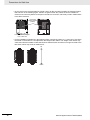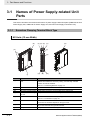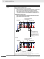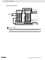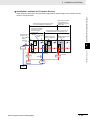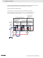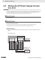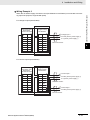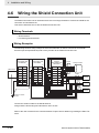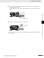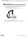
1
Machine Automation Controller NX-series System Units User’s Manual NX-PD1 NX-PF0 NX-PC0 NX-TBX01 Additional NX Unit Power Supply Units Additional I/O Power Supply Units I/O Power Supply Connection Units Shield Connection Units W523-E1-04 NOTE All rights reserved. No part of this publication may be reproduced, stored in a retrieval system, or transmitted, in any form, or by any means, mechanical, electronic, photocopying, recording, or otherwise, without the prior written permission of OMRON. No patent liability is assumed with respect to the use of the information contained herein. Moreover, because OMRON is constantly striving to improve its high-quality products, the information contained in this manual is subject to change without notice. Every precaution has been taken in the preparation of this manual. Nevertheless, OMRON assumes no responsibility for errors or omissions. Neither is any liability assumed for damages resulting from the use of the information contained in this publication. Trademarks • Sysmac and SYSMAC are trademarks or registered trademarks of OMRON Corporation in Japan and other countries for OMRON factory automation products. • Microsoft, Windows, Windows Vista, Excel, and Visual Basic are either registered trademarks or trademarks of Microsoft Corporation in the USA and other countries. • EtherCAT® is registered trademark and patented technology, licensed by Beckhoff Automation GmbH, Germany. • Safety over EtherCAT® is registered trademark and patented technology, licensed by Beckhoff Automation GmbH, Germany. • ODVA, CIP, CompoNet, DeviceNet, and EtherNet/IP are trademarks of ODVA. • The SD and SDHC logos are trademarks of SD-3C, LLC. Other company names and product names in this document are the trademarks or registered trademarks of their respective companies. Copyrights Microsoft product screen shots reprinted with permission from Microsoft Corporation. 15173 To: All Customers May 2015 OMRON Corporation Product Business Division HQ NX Series User's Manuals Notification of Correction Information Thank you for supporting OMRON and OMRON products. It was discovered that the information are incorrect from the following NX Series manuals. We sincerely apologize for this oversight. Please mark your manuals so that the corrections are noted on pages concerned, and then securely correct any required pages from this Notification to the rear of the manuals. Applicable Manuals Manual name NX-series EtherCAT® Coupler Unit User’s Manual NX-series EtherNet/IP™ Coupler Unit User’s Manual NX-series Digital I/O Units User’s Manual NX-series System Units User’s Manual Model numbers NX-ECC20 Cat. No. W519-E1-05 Issued date April 2015 NX-EIC202 W536-E1-02 April 2015 NX-ID/IA/OC /OD/MD NX-PD1/PF0/PC0 /TBX01 W521-E1-05 April 2015 W523-E1-04 April 2015 Revised Objects The following table gives the objects to revise. Cat. No. W519-E1-05 W536-E1-02 W521-E1-05 W523-E1-04 1 Subtitle No. 7-2-5 7-2-5 4-3-1 4-7-1 Subtitle name Wiring to the Screwless Clamping Terminal Block NX Series User's Manuals, Notification of Correction Information Revised Contents 1 Relevant Location: Using Twisted or Solid Wires Cat. No. Relevant page W519-E1-05 P.7-17 W536-E1-02 P.7-13 W521-E1-05 P.4-18 W523-E1-04 P.4-36 Current Contents Using Twisted or Solid Wires If you use the twisted wires or the solid wires, use the following table to determine the correct wire specifications. Terminals Classification Current capacity 2 A max. All terminals Wire type Twisted Solid wires wire Wire plating Plated Unplated Ground Conductor length (stripping length) Possible Possible Possible Possible 0.08 to 1.5 mm2 8 to 10 mm Greater than 2 A Not except ground and 4 A or less terminals Wire size AWG 28 to 16 Possible Greater than Not 4A Possible - Possible Possible 2.0 mm2 9 to 10 mm terminals *1 *1. With the NX-TB1 Terminal Block, use twisted wires to connect the ground terminal. Do not use a solid wire. Corrected Contents Using Twisted or Solid Wires If you use the twisted wires or the solid wires, use the following table to determine the correct wire specifications. Terminals ClassificaCurrent tion capacity 2 A max. All terminals Wire type Twisted wires Solid wire Plated Unplated Plated Unplated Ground Not Greater than 2 A Possible Not Possible *1 Greater than Possible Not 4A *1 Possible - Conductor length (stripping length) Possible Possible Possible Possible 0.08 to 1.5 mm2 8 to 10 mm except ground and 4 A or less terminals Wire size Possible Possible Possible Possible terminals *2 AWG 28 to 16 Possible 2.0 mm2 9 to 10 mm *2 *1. Secure wires to the screwless clamping terminal block. Refer to Securing Wires for how to secure wires. *2. With the NX-TB1 Terminal Block, use twisted wires to connect the ground terminal. Do not use a solid wire. NX Series User's Manuals, Notification of Correction Information 2 2 Relevant Location: Connecting Twisted or Solid Wires Cat. No. Relevant page W519-E1-05 P.7-19 W536-E1-02 P.7-15 W521-E1-05 P.4-20 W523-E1-04 P.4-38 Current Contents A description of Securing Wires is not provided after Connecting Twisted Wires/Solid Wires. Corrected Contents A description of Securing Wires is added after Connecting Twisted Wires/Solid Wires. The added contents are given below Securing Wires It is necessary to secure wires to the screwless clamping terminal block depending on the wire types that are used or the current flows on the wires. The following table gives the necessity for securing wires. Terminals Classification Current capacity All terminals 2 A max. Wire type Twisted wires Ferrule Plated No No Unplated Solid wire Plated Unplated No No No except ground Greater than 2 A Not Yes Not terminals Possible and 4 A or less Greater than Not Yes 4A Ground Possible Possible - No No No No terminals Use the following procedure to secure the wires. 1. Prepare a cable tie. A cable tie can be used with a width of 4 mm or less and a thickness of 1.5 mm or less. Select a cable tie correctly for the operating environment. 1.5 mm or less 4.0 mm or less 3 NX Series User's Manuals, Notification of Correction Information 2. Pass a cable tie through the hole for securing wires on the bottom of the screwless clamping terminal block Hole for securing wires Cable tie 3. Bundle the wires with a cable tie and secure them to the screwless clamping terminal block. Secure wires within the range of 30 mm from the screwless clamping terminal block. 30 mm NX Series User's Manuals, Notification of Correction Information 4 Introduction Introduction Thank you for purchasing an NX-series System Unit. This manual contains information that is necessary to use the NX-series System Unit. Please read this manual and make sure you understand the functionality and performance of the NX-series System Unit before you attempt to use it in a control system. Keep this manual in a safe place where it will be available for reference during operation. Intended Audience This manual is intended for the following personnel, who must also have knowledge of electrical systems (an electrical engineer or the equivalent). • Personnel in charge of introducing FA systems. • Personnel in charge of designing FA systems. • Personnel in charge of installing and maintaining FA systems. • Personnel in charge of managing FA systems and facilities. For programming, this manual is intended for personnel who understand the programming language specifications in international standard IEC 61131-3 or Japanese standard JIS B 3503. Applicable Products This manual covers the following product. • NX-series System Unit NX-PD /PF /PC NX-TBX NX-series System Unit User’s Manual (W523) 1 CONTENTS CONTENTS Introduction .............................................................................................................. 1 Intended Audience....................................................................................................................................... 1 Applicable Products ..................................................................................................................................... 1 Relevant Manuals ..................................................................................................... 6 Manual Structure ...................................................................................................... 7 Page Structure and Icons ............................................................................................................................ 7 Special Information ...................................................................................................................................... 8 Precaution on Terminology .......................................................................................................................... 8 Terms and Conditions Agreement .......................................................................... 9 Warranty, Limitations of Liability .................................................................................................................. 9 Application Considerations ........................................................................................................................ 10 Disclaimers ................................................................................................................................................ 10 Safety Precautions ................................................................................................. 11 Definition of Precautionary Information...................................................................................................... 11 Symbols ..................................................................................................................................................... 11 Warnings.................................................................................................................................................... 12 Cautions..................................................................................................................................................... 13 Precautions for Safe Use ....................................................................................... 15 Precautions for Correct Use.................................................................................. 20 Regulations and Standards ................................................................................... 21 Conformance to EC Directives .................................................................................................................. 21 Conformance to UL and CSA Standards ................................................................................................... 22 Conformance to Shipbuilding Standards ................................................................................................... 22 Conformance to KC Standards .................................................................................................................. 22 Software Licenses and Copyrights ............................................................................................................ 22 Unit Versions .......................................................................................................... 23 Unit Versions.............................................................................................................................................. 23 Unit Versions and Sysmac Studio Versions ............................................................................................... 25 Related Manuals ..................................................................................................... 26 Terminology ............................................................................................................ 28 Revision History ..................................................................................................... 30 Sections in this Manual ......................................................................................... 31 Section 1 1-1 Features and System Configuration Features and Types of System Units ................................................................................... 1-2 1-1-1 1-1-2 1-2 System Configuration of Slave Terminals........................................................................... 1-3 1-2-1 1-2-2 2 System Unit Features.................................................................................................................. 1-2 System Unit Types ...................................................................................................................... 1-2 Overview ..................................................................................................................................... 1-3 System Configuration.................................................................................................................. 1-3 NX-series System Unit User’s Manual (W523) CONTENTS 1-3 Model List............................................................................................................................... 1-5 1-3-1 1-3-2 1-3-3 1-3-4 1-3-5 1-4 Model Notation............................................................................................................................ 1-5 Additional NX Unit Power Supply Unit ........................................................................................ 1-6 Additional I/O Power Supply Unit................................................................................................ 1-6 I/O Power Supply Connection Unit ............................................................................................. 1-7 Shield Connection Unit ............................................................................................................... 1-7 Support Software................................................................................................................... 1-8 Section 2 Specifications 2-1 General Specifications .......................................................................................................... 2-2 2-2 Individual Specifications ...................................................................................................... 2-3 Section 3 3-1 Part Names and Functions Names of Power Supply-related Unit Parts......................................................................... 3-2 3-1-1 3-1-2 3-2 Names of Shield Connection Unit Parts .............................................................................. 3-9 3-2-1 3-2-2 Section 4 4-1 Screwless Clamping Terminal Block Type .................................................................................. 3-9 Indicators .................................................................................................................................. 3-12 Installation and Wiring Installing NX Units ................................................................................................................. 4-2 4-1-1 4-1-2 4-1-3 4-1-4 4-2 Screwless Clamping Terminal Block Type .................................................................................. 3-2 Indicators .................................................................................................................................... 3-6 Installing NX Units ...................................................................................................................... 4-2 Attaching Markers....................................................................................................................... 4-4 Removing NX Units .................................................................................................................... 4-5 Installation Orientation ................................................................................................................ 4-7 Wiring the Power Supply to the Slave Terminal ................................................................. 4-8 4-2-1 4-2-2 4-2-3 Power Supply Types ................................................................................................................... 4-8 Supplying Each Power Supply and Wiring ................................................................................. 4-9 Power Supply-related Units and Wiring Methods ......................................................................4-11 4-3 Grounding the Slave Terminal............................................................................................ 4-14 4-4 Wiring the Additional Power Supply Units........................................................................ 4-15 4-4-1 4-4-2 4-4-3 Wiring the Additional NX Unit Power Supply Unit..................................................................... 4-16 Wiring the Additional I/O Power Supply Unit ............................................................................ 4-19 Protective Devices .................................................................................................................... 4-24 4-5 Wiring the I/O Power Supply Connection Unit.................................................................. 4-28 4-6 Wiring the Shield Connection Unit .................................................................................... 4-32 4-7 Wiring the Terminals ........................................................................................................... 4-33 4-7-1 Section 5 Wiring to the Screwless Clamping Terminal Block.................................................................... 4-33 Troubleshooting 5-1 How to Check for Errors ....................................................................................................... 5-2 5-2 Checking for Errors with the Indicators .............................................................................. 5-3 5-3 Checking for Errors and Troubleshooting on the Sysmac Studio.................................... 5-5 5-3-1 5-3-2 5-3-3 Checking for Errors from the Sysmac Studio.............................................................................. 5-5 Event Codes and Corrections for Errors..................................................................................... 5-7 Meaning of Error ......................................................................................................................... 5-8 NX-series System Unit User’s Manual (W523) 3 CONTENTS 5-4 Resetting Errors .................................................................................................................. 5-11 5-5 Troubles Specific To Each Type of NX Units..................................................................... 5-12 5-5-1 5-5-2 5-6 Troubleshooting Flowchart ................................................................................................ 5-14 Section 6 6-1 Inspection and Maintenance Cleaning and Inspection ....................................................................................................... 6-2 6-1-1 6-1-2 6-2 Additional NX Unit Power Supply Unit ...................................................................................... 5-12 Additional I/O Power Supply Unit .............................................................................................. 5-13 Cleaning ...................................................................................................................................... 6-2 Periodic Inspection...................................................................................................................... 6-2 Maintenance Procedures ...................................................................................................... 6-5 Appendices A-1 Data Sheet ..............................................................................................................................A-2 A-1-1 A-1-2 A-1-3 A-1-4 A-1-5 Model List....................................................................................................................................A-2 Additional NX Unit Power Supply Unit ........................................................................................A-3 Additional I/O Power Supply Unit ................................................................................................A-6 I/O Power Supply Connection Unit..............................................................................................A-9 Shield Connection Unit..............................................................................................................A-13 A-2 Dimensions ..........................................................................................................................A-15 A-2-1 Additional NX Unit Power Supply Unit, Additional I/O Power Supply Unit, I/O Power Supply Connection Unit, and Shield Connection Unit ..............................................A-15 A-3 List of NX Objects................................................................................................................A-17 A-3-1 A-3-2 Format of Object Descriptions...................................................................................................A-17 System Units .............................................................................................................................A-18 A-4 List of Screwless Clamping Terminal Block Models ........................................................A-19 A-4-1 A-4-2 Model Notation ..........................................................................................................................A-19 List of Terminal Block Models....................................................................................................A-19 A-5 Version Information.............................................................................................................A-20 A-5-1 Relationship between Unit Versions of Units ............................................................................A-20 Index 4 NX-series System Unit User’s Manual (W523) CONTENTS NX-series System Unit User’s Manual (W523) 5 Relevant Manuals Relevant Manuals The table below provides the relevant manuals for the NX-series System Units. Read all of the manuals that are relevant to your system configuration and application to make the most of the NX-series System Units. Other manuals, such as related product manuals, are necessary for specific system configurations and applications. Refer to Related Manuals on page 26 for the related manuals. Manual name NX-series System Units User's Manual NX-series Data Reference Manual 6 Application Learning how to use NX-series System Units Referencing lists of the data that is required to configure systems with NX-series Units NX-series System Unit User’s Manual (W523) Manual Structure Manual Structure Page Structure and Icons The following page structure and icons are used in this manual. Mounting Units Level 1 heading Level 2 heading Level 3 heading Connecting Controller Components Gives the current headings. 4 Installation and Wiring Level 2 heading Level 3 heading 4-3 4-3-1 The Units that make up an NJ-series Controller can be connected simply by pressing the Units together and locking the sliders by moving them toward the back of the Units. The End Cover is connected in the same way to the Unit on the far right side of the Controller. A step in a procedure 1 Join the Units so that the connectors fit exactly. Hook Indicates a procedure. Hook holes Connector 4-3 Mounting Units 4 The yellow sliders at the top and bottom of each Unit lock the Units together. Move the sliders toward the back of the Units as shown below until they click into place. Move the sliders toward the back until they lock into place. Lock Release Slider Special information Icons indicate precautions, additional information, or reference information. Manual name 4-3-1 Connecting Controller Components 2 Page tab Gives the number of the main section. Precautions for Correct Use The sliders on the tops and bottoms of the Power Supply Unit, CPU Unit, I/O Units, Special I/O Units, and CPU Bus Units must be completely locked (until they click into place) after connecting the adjacent Unit connectors. NJ-series CPU Unit Hardware User’s Manual (W500) 4-9 Note This illustration is provided only as a sample. It may not literally appear in this manual. NX-series System Unit User’s Manual (W523) 7 Manual Structure Special Information Special information in this manual is classified as follows: Precautions for Safe Use Precautions on what to do and what not to do to ensure safe usage of the product. Precautions for Correct Use Precautions on what to do and what not to do to ensure proper operation and performance. Additional Information Additional information to read as required. This information is provided to increase understanding or make operation easier. Version Information Information on differences in specifications and functionality for CPU Units and Communications Coupler Units with different unit versions and for different versions of the Sysmac Studio is given. Note References are provided to more detailed or related information. Precaution on Terminology • In this manual, “download” refers to transferring data from the Sysmac Studio to the physical Controller and “upload” refers to transferring data from the physical Controller to the Sysmac Studio. For the Sysmac Studio, synchronization is used to both upload and download data. Here, “synchronize” means to automatically compare the data for the Sysmac Studio on the computer with the data in the physical Controller and transfer the data in the direction that is specified by the user. • In this manual, the directions in relation to the Units are given in the following figure, which shows upright installation. Up Left Right Down 8 NX-series System Unit User’s Manual (W523) Terms and Conditions Agreement Terms and Conditions Agreement Warranty, Limitations of Liability Warranties Exclusive Warranty Omron’s exclusive warranty is that the Products will be free from defects in materials and workmanship for a period of twelve months from the date of sale by Omron (or such other period expressed in writing by Omron). Omron disclaims all other warranties, express or implied. Limitations OMRON MAKES NO WARRANTY OR REPRESENTATION, EXPRESS OR IMPLIED, ABOUT NON-INFRINGEMENT, MERCHANTABILITY OR FITNESS FOR A PARTICULAR PURPOSE OF THE PRODUCTS. BUYER ACKNOWLEDGES THAT IT ALONE HAS DETERMINED THAT THE PRODUCTS WILL SUITABLY MEET THE REQUIREMENTS OF THEIR INTENDED USE. Omron further disclaims all warranties and responsibility of any type for claims or expenses based on infringement by the Products or otherwise of any intellectual property right. Buyer Remedy Omron’s sole obligation hereunder shall be, at Omron’s election, to (i) replace (in the form originally shipped with Buyer responsible for labor charges for removal or replacement thereof) the non-complying Product, (ii) repair the non-complying Product, or (iii) repay or credit Buyer an amount equal to the purchase price of the non-complying Product; provided that in no event shall Omron be responsible for warranty, repair, indemnity or any other claims or expenses regarding the Products unless Omron’s analysis confirms that the Products were properly handled, stored, installed and maintained and not subject to contamination, abuse, misuse or inappropriate modification. Return of any Products by Buyer must be approved in writing by Omron before shipment. Omron Companies shall not be liable for the suitability or unsuitability or the results from the use of Products in combination with any electrical or electronic components, circuits, system assemblies or any other materials or substances or environments. Any advice, recommendations or information given orally or in writing, are not to be construed as an amendment or addition to the above warranty. See http://www.omron.com/global/ or contact your Omron representative for published information. Limitation on Liability; Etc OMRON COMPANIES SHALL NOT BE LIABLE FOR SPECIAL, INDIRECT, INCIDENTAL, OR CONSEQUENTIAL DAMAGES, LOSS OF PROFITS OR PRODUCTION OR COMMERCIAL LOSS IN ANY WAY CONNECTED WITH THE PRODUCTS, WHETHER SUCH CLAIM IS BASED IN CONTRACT, WARRANTY, NEGLIGENCE OR STRICT LIABILITY. Further, in no event shall liability of Omron Companies exceed the individual price of the Product on which liability is asserted. NX-series System Unit User’s Manual (W523) 9 Terms and Conditions Agreement Application Considerations Suitability of Use Omron Companies shall not be responsible for conformity with any standards, codes or regulations which apply to the combination of the Product in the Buyer’s application or use of the Product. At Buyer’s request, Omron will provide applicable third party certification documents identifying ratings and limitations of use which apply to the Product. This information by itself is not sufficient for a complete determination of the suitability of the Product in combination with the end product, machine, system, or other application or use. Buyer shall be solely responsible for determining appropriateness of the particular Product with respect to Buyer’s application, product or system. Buyer shall take application responsibility in all cases. NEVER USE THE PRODUCT FOR AN APPLICATION INVOLVING SERIOUS RISK TO LIFE OR PROPERTY WITHOUT ENSURING THAT THE SYSTEM AS A WHOLE HAS BEEN DESIGNED TO ADDRESS THE RISKS, AND THAT THE OMRON PRODUCT(S) IS PROPERLY RATED AND INSTALLED FOR THE INTENDED USE WITHIN THE OVERALL EQUIPMENT OR SYSTEM. Programmable Products Omron Companies shall not be responsible for the user’s programming of a programmable Product, or any consequence thereof. Disclaimers Performance Data Data presented in Omron Company websites, catalogs and other materials is provided as a guide for the user in determining suitability and does not constitute a warranty. It may represent the result of Omron’s test conditions, and the user must correlate it to actual application requirements. Actual performance is subject to the Omron’s Warranty and Limitations of Liability. Change in Specifications Product specifications and accessories may be changed at any time based on improvements and other reasons. It is our practice to change part numbers when published ratings or features are changed, or when significant construction changes are made. However, some specifications of the Product may be changed without any notice. When in doubt, special part numbers may be assigned to fix or establish key specifications for your application. Please consult with your Omron’s representative at any time to confirm actual specifications of purchased Product. Errors and Omissions Information presented by Omron Companies has been checked and is believed to be accurate; however, no responsibility is assumed for clerical, typographical or proofreading errors or omissions. 10 NX-series System Unit User’s Manual (W523) Safety Precautions Safety Precautions Definition of Precautionary Information The following notation is used in this manual to provide precautions required to ensure safe usage of an NX-series System Unit. The safety precautions that are provided are extremely important to safety. Always read and heed the information provided in all safety precautions. The following notation is used. WARNING Caution Indicates a potentially hazardous situation which, if not avoided, could result in death or serious injury. Additionally, there may be severe property damage. Indicates a potentially hazardous situation which, if not avoided, may result in minor or moderate injury, or property damage. Symbols The circle and slash symbol indicates operations that you must not do. The specific operation is shown in the circle and explained in text. This example indicates prohibiting disassembly. The triangle symbol indicates precautions (including warnings). The specific operation is shown in the triangle and explained in text. This example indicates a precaution for electric shock. The triangle symbol indicates precautions (including warnings). The specific operation is shown in the triangle and explained in text. This example indicates a general precaution. The filled circle symbol indicates operations that you must do. The specific operation is shown in the circle and explained in text. This example shows a general precaution for something that you must do. NX-series System Unit User’s Manual (W523) 11 Safety Precautions Warnings WARNING During Power Supply Do not touch the terminal section while power is ON. Electric shock may occur. Do not attempt to take any Unit apart. In particular, high-voltage parts are present in Units that supply power while power is supplied or immediately after power is turned OFF. Touching any of these parts may result in electric shock. There are sharp parts inside the Unit that may cause injury. Fail-safe Measures Provide safety measures in external circuits to ensure safety in the system if an abnormality occurs due to malfunction of the CPU Unit, other Units, or slaves or due to other external factors affecting operation. Not doing so may result in serious accidents due to incorrect operation. Emergency stop circuits, interlock circuits, limit circuits, and similar safety measures must be provided in external control circuits. The CPU Unit will turn OFF all outputs from Basic Output Units in the following cases. The remote I/O slaves will operate according to the settings in the slaves. • If a power supply error occurs. • If the power supply connection becomes faulty. • If a CPU watchdog timer error or CPU reset occurs. • If a Controller error in the major fault level occurs. • While the CPU Unit is on standby until RUN mode is entered after the power is turned ON External safety measures must be provided to ensure safe operation of the system in such cases. The outputs may remain ON or OFF due to deposition or burning of the output relays or destruction of the output transistors. As a countermeasure for such problems, external safety measures must be provided to ensure safe operation of the system. If external power supplies for slaves or other devices are overloaded or short-circuited, the voltage will drop, outputs will turn OFF, and the system may be unable to read inputs. Provide external safety measures in control with monitoring of external power supply voltage as required so that the system operates safely in such a case. You must take fail-safe measures to ensure safety in the event of incorrect, missing, or abnormal signals caused by broken signal lines, momentary power interruptions, or other causes. Not doing so may result in serious accidents due to incorrect operation. 12 NX-series System Unit User’s Manual (W523) Safety Precautions Voltage and Current Inputs Make sure that the voltages and currents that are input to the Units and slaves are within the specified ranges. Inputting voltages or currents that are outside of the specified ranges may cause accidents or fire. Transferring Always confirm safety at the destination node before you transfer Unit configuration information, parameters, settings, or other data from tools such as the Sysmac Studio. The devices or machines may operate unexpectedly, regardless of the operating mode of the Controller. Cautions Caution Wiring When you connect a computer or other peripheral device to a Communications Coupler Unit that has a non-isolated DC power supply, either ground the 0-V side of the external power supply (i.e. Unit power supply) or do not ground it at all. If the peripheral devices are grounded incorrectly, the external power supply (i.e. Unit power supply) may be short-circuited. Never ground the 24-V side of the power supply, as shown in the following figure. NX Unit power supply Communications Coupler Unit Non-isolated DC power supply (internal power supply circuit) Peripheral device (e.g., computer) Peripheral device cable 24 V 0V Ground terminal Unit power supply Be sure that all terminal screws and cable connector screws are tightened to the torque specified in the relevant manuals. The loose screws may result in fire or malfunction. NX-series System Unit User’s Manual (W523) 13 Safety Precautions Online Editing Execute online editing only after confirming that no adverse effects will be caused by deviations in the timing of I/O. If you perform online editing, the task execution time may exceed the task period, I/O may not be refreshed with external devices, input signals may not be read, and output timing may change. 14 NX-series System Unit User’s Manual (W523) Precautions for Safe Use Precautions for Safe Use Transporting • When transporting any Unit, use the special packing box for it. Also, do not subject the Unit to excessive vibration or shock during transportation. • Do not drop any Unit or subject it to abnormal vibration or shock. Doing so may result in Unit malfunction or burning. Mounting • Mount terminal blocks and connectors only after checking the mounting location carefully. • Be sure that the terminal blocks, expansion cables, and other items with locking devices are properly locked into place. Installation • Do not apply labels or tape to the Unit. When the Unit is installed or removed, adhesive or scraps may adhere to the pins in the NX bus connector, which may result in malfunctions. • Do not touch the pins in the NX bus connector on the Unit. Dirt may adhere to the pins in the NX bus connector, which may result in malfunctions. NG NG Example: NX Unit (12 mm width) NX-series System Unit User’s Manual (W523) 15 Precautions for Safe Use • Do not write on the Communications Coupler Unit or an NX Unit with ink within the restricted region that is shown in the following figure. Also do not get this area dirty. When the Unit is installed or removed, ink or dirt may adhere to the pins in the NX bus connector, which may result in malfunctions in the Slave Terminal. Restricted region (shaded portion) Communications Coupler Unit or NX Unit NX Unit • For the installation orientations in the following figure, support the cables, e.g., with a duct, so that the End Plate on the bottom is not subjected to the weight of the cables. The weight of the cables may cause the bottom End Plate to slide downward so that the Slave Terminal is no longer secured to the DIN Track, which may result in malfunctions. Up Down 16 NX-series System Unit User’s Manual (W523) Precautions for Safe Use Wiring • Double-check all switches and other settings and double-check all wiring to make sure that they are correct before turning ON the power supply. Use the correct wiring parts and tools when you wire the system. • Do not pull on the cables or bend the cables beyond their natural limit. Also, do not place heavy objects on top of the cables or other wiring lines. Doing so may break the cable. • When wiring or installing the Units, do not allow metal fragments to enter the Units. • Do not press the flat-blade screwdriver straight into the release holes on a screwless clamping terminal block. Doing so may damage the terminal block. NG OK • When you insert a flat-blade screwdriver into a release hole on a screwless clamping terminal block, press it down with a force of 30N or less. Applying excessive force may damage the terminal block. • Do not incline or twist the flat-blade screwdriver while it is in a release hole on a screwless clamping terminal block. Doing so may damage the terminal block. NG NG • Use crimp terminals for wiring the M3 screw terminal blocks. Do not connect bare stranded wires directly to the M3 screw terminal blocks. Power Supply Design • Use all Units within the I/O power supply ranges that are given in the specifications. • Supply sufficient power according to the contents of this manual. • Use the power supply voltage that is specified in this manual. • Do not apply voltages that exceed the rated value to any Input Unit. • Do not apply voltages or connect loads to the Output Units or slaves in excess of the maximum ratings. • Inrush current occurs when the power supply is turned ON. When selecting fuses or breakers for external circuits, consider their fusing and detection characteristics as well as the above precautions and allow sufficient margin in shut-off performance. • Install external breakers and take other safety measures against short-circuiting and overcurrents in external wiring. Turning ON the Power Supply • When you set the Operating Mode at Startup, confirm that no adverse effect will occur in the system. NX-series System Unit User’s Manual (W523) 17 Precautions for Safe Use Actual Operation • Before you start operation, always register the NX Units that are connected to the Communications Coupler Unit in the host communications master as the Unit Configuration Information. • Check the user program, data, and parameter settings for proper execution before you use them for actual operation. • If you change the fail-soft operation setting, the output status when the error occurs may also change. Confirm safety before you change the fail-soft operation setting. • If you use fail-soft operation, write programming to determine whether Unit I/O data is valid. Without such programming, the user program cannot distinguish between Units for which I/O refreshing is continued and Units for which I/O refreshing is stopped. Turning OFF the Power Supply • Do not disconnect the cable or turn OFF the power supply to the Controller or a Slave Terminal when downloading data or the user program from Sysmac Studio. • Always turn OFF the external power supply to the Units before attempting any of the following. Mounting or removing an NX Unit, Communications Coupler Unit, or CPU Unit Assembling Units Setting DIP switches or rotary switches Connecting or wiring cables Attaching or removing terminal blocks or connectors Units that supply power continue to supply power to the Units for up to several seconds after the power supply is turned OFF. The PWR indicator remains lit as long as power is supplied. Confirm that the PWR indicator is not lit before you perform any of the above. Operation • Confirm that the controlled system will not be adversely affected before you perform any of the following operations. Changing the operating mode of the CPU Unit (including changing the setting of the Operating Mode at Startup) Changing the user program or settings Changing set values or present values Forced refreshing • Always sufficiently check the safety at the connected devices before you change the settings of a slave or Unit. General Communications • Do not exceed the ranges that are given in the specifications for the communications distance and number of connected Units. • Refer to the user’s manual for the Communications Coupler Unit for precautions for the safe use of communications with the connected Communications Coupler Unit. Unit Replacement • When you replace a Unit, start operation only after you transfer the settings and variables that are required for operation to the new Unit. 18 NX-series System Unit User’s Manual (W523) Precautions for Safe Use Disposal • Dispose of the product according to local ordinances as they apply. NX-series System Unit User’s Manual (W523) 19 Precautions for Correct Use Precautions for Correct Use Storage, Mounting, and Wiring • Follow the instructions in this manual to correctly perform installation and wiring. • Do not operate or store the Units in the following locations. Doing so may result in malfunction, in operation stopping, or in burning. Locations subject to direct sunlight Locations subject to temperatures or humidity outside the range specified in the specifications Locations subject to condensation as the result of severe changes in temperature Locations subject to corrosive or flammable gases Locations subject to dust (especially iron dust) or salts Locations subject to exposure to water, oil, or chemicals Locations subject to shock or vibration • Take appropriate and sufficient countermeasures during installation in the following locations. Locations subject to strong, high-frequency noise Locations subject to static electricity or other forms of noise Locations subject to strong electromagnetic fields Locations subject to possible exposure to radioactivity Locations close to power lines • Before touching a Unit, be sure to first touch a grounded metallic object in order to discharge any static build-up. • Use the rated power supply voltage for the Units that supply power. Take appropriate measures to ensure that the specified power with the rated voltage and frequency is supplied in places where the power supply is unstable. • Install the Units away from sources of heat and ensure proper ventilation. Not doing so may result in malfunction, in operation stopping, or in burning. • Do not allow foreign matter to enter the openings in the Unit. Doing so may result in Unit burning, electric shock, or failure. Actual Operation • If you change the event level of an error, the output status when the error occurs may also change. Confirm safety before you change an event level. Turning OFF the Power Supply • Do not turn OFF the power supply while data is being transferred. • Do not turn OFF the power supply while parameters are being written to the Communications Coupler Unit or NX Units. General Communications • Refer to the user’s manual for the Communications Coupler Unit for precautions for the correct use of communications with the connected Communications Coupler Unit. 20 NX-series System Unit User’s Manual (W523) Regulations and Standards Regulations and Standards Conformance to EC Directives Applicable Directives • EMC Directives • Low Voltage Directive Concepts EMC Directives OMRON devices that comply with EC Directives also conform to the related EMC standards so that they can be more easily built into other devices or the overall machine. The actual products have been checked for conformity to EMC standards.*1 Whether the products conform to the standards in the system used by the customer, however, must be checked by the customer. EMC-related performance of the OMRON devices that comply with EC Directives will vary depending on the configuration, wiring, and other conditions of the equipment or control panel on which the OMRON devices are installed. The customer must, therefore, perform the final check to confirm that devices and the overall machine conform to EMC standards. *1. Applicable EMC (Electromagnetic Compatibility) standards are as follows: EMS (Electromagnetic Susceptibility): EN 61131-2 EMI (Electromagnetic Interference): EN 61131-2 (Radiated emission: 10-m regulations). Low Voltage Directive Always ensure that devices operating at voltages of 50 to 1,000 VAC and 75 to 1,500 VDC meet the required safety standards. The applicable directive is EN 61131-2. Conformance to EC Directives The NX-series Units comply with EC Directives. To ensure that the machine or device in which the NX-series Units are used complies with EC Directives, the following precautions must be observed. • The NX-series Units must be installed within a control panel. • You must use reinforced insulation or double insulation for the DC power supplies that are connected as the Unit power supplies and I/O power supplies for the NX-series Units. We recommend that you use the OMRON S8JX-series Power Supplies. EMC standard compliance was confirmed for the recommended Power Supplies. • NX-series Units that comply with EC Directives also conform to the Common Emission Standard (EN 61131-2). Radiated emission characteristics (10-m regulations) may vary depending on the configuration of the control panel used, other devices connected to the control panel, wiring, and other conditions. You must therefore confirm that the overall machine or equipment in which the NX-series Units are used complies with EC Directives. • You must use power supplies with an output hold time of 10 ms or longer for the DC power supplies that are connected as the Unit power supplies and I/O power supplies for the NX-series Units. • This is a Class A product (for industrial environments). In a residential environment, it may cause radio interference. If radio interference occurs, the user may be required to take appropriate measures. NX-series System Unit User’s Manual (W523) 21 Regulations and Standards Conformance to UL and CSA Standards Some NX-series products comply with UL and CSA standards. If you use an NX-series product that complies with UL or CSA standards and the machinery or system in which you use the NX-series product must also comply with the standards, refer to the Instruction Sheet that is provided with the product. The Instruction Sheet provides the application conditions for complying with the standards. Conformance to Shipbuilding Standards Some NX-series products comply with shipbuilding standards. If you use an NX-series product that complies with shipbuilding standards and the machinery or system in which you use the NX-series product must also comply with the standards, consult with your OMRON representative. Application conditions are defined according to the installation location. Application may not be possible for some installation locations. Usage Conditions for NK and LR Shipbuilding Standards • The NX-series Units must be installed within a control panel. • Gaps in the door to the control panel must be completely filled or covered with gaskets or other material. • The following noise filter must be connected to the power supply line. Name Noise filter Manufacturer Cosel Co., Ltd. Model TAH-06-683 Conformance to KC Standards Observe the following precaution if you use NX-series Units in Korea. Class A Device (Broadcasting Communications Device for Office Use) This device obtained EMC registration for office use (Class A), and it is intended to be used in places other than homes. Sellers and/or users need to take note of this. Software Licenses and Copyrights This product incorporates certain third party software. The license and copyright information associated with this software is available at http://www.fa.omron.co.jp/nj_info_e/. 22 NX-series System Unit User’s Manual (W523) Unit Versions Unit Versions This section describes the notation that is used for unit versions, the confirmation method for unit versions, and the relationship between unit versions and Sysmac Studio versions. Unit Versions A “unit version” has been introduced to manage the Units in the NX Series according to differences in functionality accompanying Unit upgrades. Notation of Unit Versions on Products The unit version is given with the Unit specifications on the side of the Unit or in the notched area. Notched area Unit specifications Lot number and unit version Unit model number LOT No. Lot number Unit version The following information is provided in the Unit specifications on the Unit. Name Unit model number Function Gives the model of the Unit. Unit version Gives the unit version of the Unit. Lot number Gives the lot number of the Unit. DDMYY: Lot number, : Used by OMRON. “M” gives the month (1 to 9: January to September, X: October, Y: November, Z: December) NX-series System Unit User’s Manual (W523) 23 Unit Versions The following information is provided in the notched area on the Unit. Name Lot number and unit version Function Gives the lot number and unit version of the Unit. • DDMYY: Lot number, : Used by OMRON. “M” gives the month (1 to 9: January to September, X: October, Y: November, Z: December) • 1: Unit version The decimal portion of the unit version is omitted. (It is provided in the Unit specifications.) Confirming Unit Versions with the Sysmac Studio You can use the Production Information on the Sysmac Studio to check the unit versions of Communications Coupler Unit and NX Units. The following example is for the EtherCAT Slave Terminal. Refer to the user's manual for the connected Communications Coupler Unit for details on how to check the unit versions of the Units on any other type of Slave Terminal. 1 Double-click EtherCAT under Configurations and Setup in the Multiview Explorer, and then double-click the EtherCAT Coupler Unit. Or, right-click the EtherCAT Coupler Unit and select Edit from the menu. The Edit Slave Terminal Configuration Tab Page is displayed. You can also display the Edit Slave Terminal Configuration Tab Page with any of the following operations. Double-click EtherCAT under Configurations and Setup in the Multiview Explorer, right-click the EtherCAT Coupler Unit in the EtherCAT Configuration Edit Tab Page, and select Edit Slave Terminal Configuration. Or, select the EtherCAT Coupler Unit on the EtherCAT Configuration Edit Tab Page click the Edit Slave Terminal Configuration Button. 2 3 Go online. Right-click the EtherCAT Coupler Unit and select Display Production Information from the menu. The Production Information Dialog Box is displayed. Simple Display Detailed Display In this example, “Ver.1.0” is displayed next to the Unit model. The following items are displayed. • Slot number • Unit model number 24 NX-series System Unit User’s Manual (W523) Unit Versions • Unit version • Serial number • Lot number • Hardware version • Software version • Total power-ON time The software version is displayed only for Units that contain software. Version Information The total power-ON time is provided by function to monitor the total power-ON time. The function to monitor the total power-ON time was added for a version upgrade. Refer to the user's manual for the Communications Coupler Unit for the versions that support monitoring the total power-ON time. Unit Versions and Sysmac Studio Versions The functions that are supported depend on the unit version of the Unit. The version of Sysmac Studio that supports the functions that were added for an upgrade is also required to use those functions. Refer to A-5 Version Information on page A-20 for the functions that are supported by each unit version. NX-series System Unit User’s Manual (W523) 25 Related Manuals Related Manuals The following table shows related manuals. Use these manuals for reference. Manual name NX-series System Units User’s Manual Cat. No. W523 Model numbers NX-PD1 NX-PF0 NX-PC0 NX-TBX01 NX- NX-series Data Reference Manual W525 Sysmac Studio Version 1 Operation Manual W504 SYSMACSE2 NJ/NX-series Troubleshooting Manual W503 NX701- NJ501- NJ301- NJ101- Application Learning how to use NX-series System Units Description The hardware and functions of the NX-series System Units are described. Referencing lists of the data that is required to configure systems with NX-series Units Learning about the operating procedures and functions of the Sysmac Studio. Learning about the errors that may be detected in an NJ/NX-series Controller. Lists of the power consumptions, weights, and other NX Unit data that is required to configure systems with NX-series Units are provided. NX-series EtherCAT Coupler Unit User’s Manual W519 NX-ECC20 Learning how to use an NX-series EtherCAT Coupler Unit and EtherCAT Slave Terminals NX-series Ether- W536 NX-EIC202 Learning how to use an NX-series EtherNet/IP Coupler Unit and EtherNet/IP Slave Terminals Net/IPTM Coupler Unit User's Manual 26 Describes the operating procedures of the Sysmac Studio. Concepts on managing errors that may be detected in an NJ/NX-series Controller and information on individual errors are described. Use this manual together with the NJ-series CPU Unit Hardware User's Manual (Cat. No. W500) or NX-series CPU Unit Hardware User's Manual (Cat. No. W535) and with the NJ/NX-series CPU Unit Software User's Manual (Cat. No. W501). The following items are described: the overall system and configuration methods of an EtherCAT Slave Terminal (which consists of an NX-series EtherCAT Coupler Unit and NX Units), and information on hardware, setup, and functions to set up, control, and monitor NX Units through EtherCAT. The following items are described: the overall system and configuration methods of an EtherNet/IP Slave Terminal (which consists of an NX-series EtherNet/IP Coupler Unit and NX Units), and information on hardware, setup, and functions to set up, control, and monitor NX Units. NX-series System Unit User’s Manual (W523) Related Manuals Manual name NJ/NX-series CPU Unit Built-in EtherCAT Port User's Manual Cat. No. W505 Model numbers NX701- NJ501- NJ301- NJ101- Application Using the built-in EtherCAT port on an NJ/NX-series CPU Unit. Description Information on the built-in EtherCAT port is provided. This manual provides an introduction and provides information on the configuration, features, and setup. Use this manual together with the NJ-series CPU Unit Hardware User's Manual (Cat. No. W500) or NX-series CPU Unit Hardware User's Manual (Cat. No. W535) and with the NJ/NX-series CPU Unit Software User's Manual (Cat. No. W501). NX-series System Unit User’s Manual (W523) 27 Terminology Terminology Term application layer status, AL status Abbreviation --- CAN application protocol over EtherCAT CAN in Automation CoE Communications Coupler Units --- DC time --- device profile --- device variable --- distributed clock DC EtherCAT slave controller EtherCAT slave information EtherCAT state machine EtherCAT Technology Group ESC ESI ESM ETG I/O map settings --- I/O port --- I/O refreshing --- index network configuration information ----- NX bus object ----- object dictionary OD Operational --- PDO communications Pre-Operational ----- primary periodic task process data ----- process data communications --- 28 CiA Description Status for indicating information on errors that occur in an application on a slave. A CAN application protocol service implemented on EtherCAT. CiA is the international users' and manufacturers' group that develops and supports higher-layer protocols. The generic name of an interface unit for remote I/O communications on a network between NX Units and a host network master. EtherCAT slaves that support distributed clock synchronization have a clock that is shared by all slaves in the network. The time that is based on this distributed clock is called the DC time. A collection of device dependent information and functionality providing consistency between similar devices of the same device type. A variable in the NJ/NX-series CPU Unit to which process data on an EtherCAT slave is allocated. Slave process data is accessed by directly reading and writing device variables from user applications on the NJ/NX-series CPU Unit. Clock distribution mechanism used to synchronize EtherCAT slaves and the EtherCAT master. A controller for EtherCAT slave communications. An XML file that contains setting information for an EtherCAT slave. An EtherCAT communications state machine. The ETG is a global organization in which OEM, end users, and technology providers join forces to support and promote the further technology development. Settings that assign variables to I/O ports. Assignment information between I/O ports and variables. A logical interface that is used by the CPU Unit to exchange data with an external device (slave or Unit). Cyclic data exchange with external devices that is performed with predetermined memory addresses. Address of an object within an application process. The EtherCAT network configuration information held by the EtherCAT master. The NX-series internal bus. An abstract representation of a particular component within a device, which consists of data, parameters, and methods. Data structure that contains description of data type objects, communication objects and application objects. A state in EtherCAT communications where SDO communications and I/O are possible. An acronym for process data communications. A state in EtherCAT communications where only SDO communications are possible with the slaves, i.e., no I/O can be performed. The task with the highest priority. Collection of application objects designated to be downloaded cyclically or acyclically for the purpose of measurement and control. One type of EtherCAT communications in which process data objects (PDOs) are used to exchange information cyclically and in realtime. This is also called PDO communications. NX-series System Unit User’s Manual (W523) Terminology process data object Abbreviation PDO receive PDO Safe-Operational RxPDO --- SDO communications --- service data object SDO Slave Information Interface Slave Terminal SII --- subindex Sync0 ----- Sync Manager SM task period --- transmit PDO TxPDO Term NX-series System Unit User’s Manual (W523) Description A structure that describes the mappings of parameters that have one or more process data entities. A process data object received by an EtherCAT slave. A state in EtherCAT communications where only SDO communications and reading input data from slaves are possible. Outputs from slaves are not performed. One type of EtherCAT communications in which service data objects (SDOs) are used to transmit information whenever required. CoE asynchronous mailbox communications where all objects in the object dictionary can be read and written. Slave information that is stored in non-volatile memory in the slave. A building-block remote I/O terminal to which a Communications Coupler Unit and NX Units are mounted Sub-address of an object within the object dictionary. A signal that gives the interrupt timing based on the distributed clock (DC) in EtherCAT communications. The slaves execute controls according to this interrupt timing. Collection of control elements to coordinate access to concurrently used objects. The interval at which the primary periodic task or a periodic task is executed. A process data object sent from an EtherCAT slave. 29 Revision History Revision History A manual revision code appears as a suffix to the catalog number on the front and back covers of the manual. Cat. No. W523-E1-04 Revision code Revision code 01 02 03 04 30 Date April 2013 June 2013 September 2013 April 2015 Revised content Original production Corrected mistakes Added information on the NX-PF0730 and corrected mistakes. Made changes accompanying the addition of the NX-series CPU Unit and corrected mistakes. NX-series System Unit User’s Manual (W523) Sections in this Manual Sections in this Manual 1 1 Features and System Configuration 2 3 2 Specifications 4 3 Part Names and Functions 5 4 Installation and Wiring 6 5 Troubleshooting 6 A I Inspection and Maintenance 9 A I Appendices Index NX-series System Unit User’s Manual (W523) 31 Sections in this Manual 32 NX-series System Unit User’s Manual (W523) 1 Features and System Configuration This section describes NX system configuration and System Unit types. 1-1 Features and Types of System Units . . . . . . . . . . . . . . . . . . . . . . . . . . . . . . 1-2 1-1-1 1-1-2 System Unit Features . . . . . . . . . . . . . . . . . . . . . . . . . . . . . . . . . . . . . . . . . . . . 1-2 System Unit Types . . . . . . . . . . . . . . . . . . . . . . . . . . . . . . . . . . . . . . . . . . . . . . 1-2 1-2 System Configuration of Slave Terminals . . . . . . . . . . . . . . . . . . . . . . . . . . 1-3 1-2-1 1-2-2 Overview . . . . . . . . . . . . . . . . . . . . . . . . . . . . . . . . . . . . . . . . . . . . . . . . . . . . . . 1-3 System Configuration . . . . . . . . . . . . . . . . . . . . . . . . . . . . . . . . . . . . . . . . . . . . 1-3 1-3 Model List . . . . . . . . . . . . . . . . . . . . . . . . . . . . . . . . . . . . . . . . . . . . . . . . . . . . 1-5 1-3-1 1-3-2 1-3-3 1-3-4 1-3-5 Model Notation . . . . . . . . . . . . . . . . . . . . . . . . . . . . . . . . . . . . . . . . . . . . . . . . . Additional NX Unit Power Supply Unit . . . . . . . . . . . . . . . . . . . . . . . . . . . . . . . Additional I/O Power Supply Unit . . . . . . . . . . . . . . . . . . . . . . . . . . . . . . . . . . . I/O Power Supply Connection Unit . . . . . . . . . . . . . . . . . . . . . . . . . . . . . . . . . . Shield Connection Unit . . . . . . . . . . . . . . . . . . . . . . . . . . . . . . . . . . . . . . . . . . . 1-5 1-6 1-6 1-7 1-7 1-4 Support Software . . . . . . . . . . . . . . . . . . . . . . . . . . . . . . . . . . . . . . . . . . . . . . 1-8 NX-series System Unit User’s Manual (W523) 1-1 1 Features and System Configuration 1-1 Features and Types of System Units This section describes features and types of System Units. 1-1-1 System Unit Features System Units are Units used to build the system for separating power supply systems or supplying power in the midstream in a Slave Terminal. The NX-series System Units provide the following features. Simple I/O Wiring with a Screwless Clamping Terminal Block The terminal block is a screwless clamping terminal block. You can connect the wires simply by pushing the ferrules into the terminals. The amount of wiring work is reduced without requiring the use of screws. 1-1-2 System Unit Types The types of System Units are as follows. Type System Units Additional NX Unit Power Supply Unit Additional I/O Power Supply Unit I/O Power Supply Connection Unit Shield Connection Unit Purpose These Units are used as required to build a Slave Terminal. This Unit is used when the NX Unit power supply is insufficient. This Unit is used when the I/O power supply is insufficient or to separate the I/O power supply in the Slave Terminal. This Unit is used when the I/O power supply terminals are insufficient for connections to external I/O devices. This Unit is used to ground more than one shield from external I/O connections to the same ground. Refer to 1-3 Model List on page 1-5 for details on System Unit models. 1-2 NX-series System Unit User’s Manual (W523) 1 Features and System Configuration System Configuration of Slave Terminals 1-2-1 1 Overview The NX Units can be flexibly combined with a Communications Coupler Unit to achieve the optimum remote I/O slave for the application with less wiring, less work, and less space. System Configuration The following figure shows an example of the system configuration when an EtherCAT Coupler Unit is used as a Communications Coupler Unit. Refer to the user’s manual for the connected Communications Coupler Unit for details on how to configure the system when any other type of Communications Coupler Unit is used. (E) Sysmac Studio Support Software (A) EtherCAT master NJ/NX-series CPU Unit or master from another manufacturer Connection to peripheral USB port or built-in EtherNet/IP port on NJ/NX-series CPU Unit .xml (F) ESI files Built-in EtherCAT port (E) Sysmac Studio Support Software (G) Communications cable Ethernet cables Peripheral USB port • EtherCAT Slave Terminal (B) NX Series EtherCAT Coupler Unit NX-ECC20 Connection to peripheral USB port on EtherCAT Coupler Unit .xml (D) End Cover (F) ESI files (C) NX Units NX-series System Unit User’s Manual (W523) 1-3 1-2-1 Overview The Slave Terminal is a building-block remote I/O slave that is created by mounting a group of NX Units to a Communications Coupler Unit. 1-2-2 1-2 System Configuration of Slave Terminals 1-2 1 Features and System Configuration Letter (A) EtherCAT master *1 (B) EtherCAT Coupler Unit Item Description The EtherCAT master manages the network, monitors the status of slaves, and exchanges I/O data with slaves. The EtherCAT Coupler Unit serves as an interface for process data communications on the EtherCAT network between the NX Units and the EtherCAT master. The I/O data for the NX Units is accumulated in the EtherCAT Coupler Unit and then all of the data is exchanged with the EtherCAT master at the same time. (C) (D) (E) (F) (G) NX Units End Cover Sysmac Studio Support Software ESI (EtherCAT Slave Information) file Communications cable The EtherCAT Coupler Unit can also perform message communications (SDO communications) with the EtherCAT master. The NX Units perform I/O processing with connected external devices. The NX Units perform process data communications with the EtherCAT master through the EtherCAT Coupler Unit. The End Cover is attached to the end of the Slave Terminal. The Sysmac Studio runs on a personal computer and it is used to configure the EtherCAT network and EtherCAT Slave Terminal, and to program, monitor, and troubleshoot the Controllers. You can connect the computer, in which the Sysmac Studio is installed, to the peripheral USB port or built-in EtherNet/IP port on an NJ/NX-series CPU Unit to set up the EtherCAT Slave Terminal. Or you can connect it to the peripheral USB port on the EtherCAT Coupler Unit to set up the EtherCAT Slave Terminal. The ESI file contains information that is unique to the EtherCAT Slave Terminal in XML format. You can load the ESI file into the Sysmac Studio to easily allocate Slave Terminal process data and configure other settings. The ESI files for OMRON EtherCAT slaves are already installed in the Sysmac Studio. You can update the Sysmac Studio to get the ESI files for the most recent models. Use a double-shielded cable with aluminum tape and braiding of Ethernet category 5 (100Base-TX) or higher, and use straight wiring. *1. An EtherCAT Slave Terminal cannot be connected to any of the OMRON CJ1W-NC81/82 Position Control Units even though they can operate as EtherCAT masters. 1-4 NX-series System Unit User’s Manual (W523) 1 Features and System Configuration 1-3 Model List 1-3 Model List 1-3-1 Model Notation 1 The System Unit models are assigned based on the following rules. Power Supply-related Units NX - Unit type PD : Additional NX Unit Power Supply Unit PF : Additional I/O Power Supply Unit PC : I/O Power Supply Connection Unit NX Unit power supply voltage 0 : No NX Unit power supply function 1 : 24 VDC, no-isolation I/O power supply voltage and maximum current of I/O power supply 0 : No I/O power supply function 6: 5 to 24 VDC, 4 A 7: 5 to 24 VDC, 10 A I/O power supply connection terminal 0 : No I/O power supply connection terminal 1 : IOG 2 : IOV 3 : IOG/IOV Additional function 0 : Not supported. NX-series System Unit User’s Manual (W523) 1-5 1-3-1 Model Notation Model notation for the power supply-related Units (Additional NX Unit Power Supply Unit, Additional I/O Power Supply Unit and I/O Power Supply Connection Unit) differs from that of System Units other than power supply-related Units. 1 Features and System Configuration System Units Other Than Power Supply-related Units NX - Unit type END : End Cover TBX : Shield Connection Unit Additional number 01 : Additional number 1-3-2 Additional NX Unit Power Supply Unit This section shows a list of Additional NX Unit Power Supply Units. Refer to A-1-2 Additional NX Unit Power Supply Unit on page A-3 for details. Screwless Clamping Terminal Block, 12 mm Width Model NX-PD1000 1-3-3 Rated power supply voltage 24 VDC NX Unit power supply capacity 10 W max. Reference P. A-4 Additional I/O Power Supply Unit This section shows a list of Additional I/O Power Supply Units. Refer to A-1-3 Additional I/O Power Supply Unit on page A-6 for details. Screwless Clamping Terminal Block, 12 mm Width Model 1-6 Rated power supply voltage Maximum current of I/O power supply Reference NX-PF0630 5 to 24 VDC 4A P. A-7 NX-PF0730 5 to 24 VDC 10 A P. A-8 NX-series System Unit User’s Manual (W523) 1 Features and System Configuration 1-3-4 I/O Power Supply Connection Unit 1-3 Model List This section shows a list of I/O Power Supply Connection Units. Refer to A-1-4 I/O Power Supply Connection Unit on page A-9 for details. Screwless Clamping Terminal Block, 12 mm Width Number of I/O power supply terminals Current capacity of I/O power supply terminal Reference NX-PC0020 IOV: 16 terminals NX-PC0010 IOG: 16 terminals P. A-11 IOV: 8 terminals P. A-12 NX-PC0030 4 A/terminal max. 1-3-4 I/O Power Supply Connection Unit Model 1 P. A-10 IOG: 8 terminals 1-3-5 Shield Connection Unit This section shows a list of Shield Connection Units. Refer to A-1-5 Shield Connection Unit on page A-13 for details. Screwless Clamping Terminal Block, 12 mm Width Model NX-TBX01 Number of shield terminals 14 terminals Reference P. A-14 (The following two terminals are functional ground terminals.) NX-series System Unit User’s Manual (W523) 1-7 1 Features and System Configuration 1-4 Support Software Refer to A-5 Version Information on page A-20 for information on the Support Software that can perform the settings of the Slave Terminal. 1-8 NX-series System Unit User’s Manual (W523) 2 Specifications This section describes the general specifications and individual specifications of System Units. 2-1 General Specifications . . . . . . . . . . . . . . . . . . . . . . . . . . . . . . . . . . . . . . . . . 2-2 2-2 Individual Specifications . . . . . . . . . . . . . . . . . . . . . . . . . . . . . . . . . . . . . . . . 2-3 NX-series System Unit User’s Manual (W523) 2-1 2 Specifications 2-1 General Specifications This table shows the general specifications of all System Units. Item Enclosure Grounding methods Operating environment Ambient operating temperature Ambient operating humidity Atmosphere Ambient storage temperature Altitude Pollution degree Noise immunity Overvoltage category EMC immunity level Vibration resistance Specification Mounted in a panel Ground of 100 Ω or less 0 to 55C 10 to 95% RH (with no icing or condensation) Must be free from corrosive gases. 25 to 70C (with no icing or condensation) 2,000 m max. Pollution degree 2 or less: Conforms to JIS B 3502 and IEC 61131-2. Conforms to IEC 61000-4-4, 2 kV (power supply line) Category II: Conforms to JIS B 3502 and IEC 61131-2. Zone B Conforms to IEC 60068-2-6. 5 to 8.4 Hz with amplitude of 3.5 mm, 8.4 to 150 Hz, acceleration of 9.8 m/s2 100 min each in X, Y, and Z directions (10 sweeps of 10 min each = 100 min total) Shock resistance Conforms to IEC 60068-2-27, 147 m/s2, 3 times each in X, Y, and Z directions Insulation resistance Dielectric strength *1 Applicable standards*2 *1 cULus: Listed (UL508), ANSI/ISA 12.12.01, EC: EN 61131-2, C-Tick, KC: KC Registration, NK, LR *1. Varies with NX Unit Models. Refer to A-1 Data Sheet on page A-2 for the specifications of NX Units. *2. Refer to the OMRON website (www.ia.omron.com) or ask your OMRON representative for the most recent applicable standards for each model. 2-2 NX-series System Unit User’s Manual (W523) 2 Specifications Individual Specifications 2-2 Individual Specifications 2-2 Refer to A-1 Data Sheet on page A-2 for the specifications of individual System Units. 2 NX-series System Unit User’s Manual (W523) 2-3 2 Specifications 2-4 NX-series System Unit User’s Manual (W523) Part Names and Functions 3 This section describes the names and functions of the System Unit parts. 3-1 Names of Power Supply-related Unit Parts . . . . . . . . . . . . . . . . . . . . . . . . . 3-2 3-1-1 3-1-2 Screwless Clamping Terminal Block Type . . . . . . . . . . . . . . . . . . . . . . . . . . . . 3-2 Indicators . . . . . . . . . . . . . . . . . . . . . . . . . . . . . . . . . . . . . . . . . . . . . . . . . . . . . 3-6 3-2 Names of Shield Connection Unit Parts . . . . . . . . . . . . . . . . . . . . . . . . . . . 3-9 3-2-1 3-2-2 Screwless Clamping Terminal Block Type . . . . . . . . . . . . . . . . . . . . . . . . . . . . 3-9 Indicators . . . . . . . . . . . . . . . . . . . . . . . . . . . . . . . . . . . . . . . . . . . . . . . . . . . . 3-12 NX-series System Unit User’s Manual (W523) 3-1 3 Part Names and Functions 3-1 Names of Power Supply-related Unit Parts This section describes the names and functions of power supply-related Unit parts (Additional NX Unit Power Supply Unit, Additional I/O Power Supply Unit, and I/O Power Supply Connection Unit). 3-1-1 Screwless Clamping Terminal Block Type NX Units (12 mm Width) (B) (B) (C) (D) (E) (C) (F) (A) (G) (I) 3-2 (C) (E) (C) (H) Letter (A) Name Marker attachment locations Function The locations where markers are attached. The markers made by OMRON are installed for the factory setting. Commercially available markers can also be installed. (B) (C) (D) (E) (F) NX bus connector Unit hookup guides DIN Track mounting hooks Protrusions for removing the Unit Indicators The indicators show the current operating status of the Unit. (G) Terminal block Refer to 3-1-2 Indicators on page 3-6 The terminal block is used to connect external devices. (H) DIN Track contact plate (I) Unit specifications Refer to 4-1-2 Attaching Markers on page 4-4 This connector is used to connect each Unit. These guides are used to connect two Units. These hooks are used to mount the NX Unit to a DIN Track. The protrusions to hold when removing the Unit. The number of terminals depends on the type of Unit. This plate is used to contact the ground terminal with a DIN Track. It is only on the Units that have ground terminals. The specifications of the Unit are given. NX-series System Unit User’s Manual (W523) 3 Part Names and Functions There are two models of Screwless Clamping Terminal Blocks: NX-TB2 and NX-TB1. Each model has three types of terminal blocks: 8-terminal type, 12-terminal type, and 16-terminal type. Use the 8-terminal type and the 16-terminal type for the power supply-related Units. NX-TB2 (A) (B) B1 A1 B1 A2 B2 A2 B2 A3 B3 A3 B3 A4 B4 A4 B4 A5 B5 A5 B5 A6 B6 A6 B6 A7 B7 A7 B7 A8 B8 A8 B8 8-terminal type (C) 3 3-1-1 Screwless Clamping Terminal Block Type (D) A1 16-terminal type NX-TB1 (A) (B) A1 B1 A1 B1 A2 B2 A2 B2 A3 B3 A3 B3 A4 B4 A4 B4 A5 B5 A5 B5 A6 B6 A6 B6 A7 B7 A7 B7 A8 B8 A8 B8 8-terminal type NX-series System Unit User’s Manual (W523) 3-1 Names of Power Supply-related Unit Parts Terminal Blocks (C) 16-terminal type 3-3 3 Part Names and Functions Letter (A) Name Terminal number indications Function Terminal numbers for which A and B indicate the column, and 1 to 8 indicate the line are displayed. The terminal number is a combination of column and line, i.e. A1 to A8 and B1 to B8. (B) Release holes (C) (D) Terminal holes Ground terminal mark The terminal number indications are the same regardless of the number of terminals on the terminal block. Insert a flat-blade screwdriver into these holes to connect and remove the wires. The wires are inserted into these holes. This mark indicates ground terminals. It is only on the NX-TBC2. The NX-TB2 and NX-TB1 Terminal Blocks have different terminal current capacities. The NX-TB2 has 10 A and NX-TB1 has 4 A. To differentiate between the two models of Terminal Blocks, use the terminal number column indications. The Terminal Block with white letters on a dark background is the NX-TB2. You can mount either NX-TB1 or NX-TB2 Terminal Blocks to the Units that the current capacity specification of the terminals is 4 A or less. You can only mount the NX-TB2 Terminal Block to the Units that the current capacity specification of the terminals is greater than 4 A. Additional Information • Each power supply-related Unit is compatible with only one of three types of terminal blocks. You cannot use a terminal block with a number of terminals that differs from the specifications for a particular Unit. • The 8-terminal type does not have terminal holes and release holes for following terminal numbers. A2, A4, A6, A8, B2, B4, B6, and B8 3-4 NX-series System Unit User’s Manual (W523) 3 Part Names and Functions The following indicates the Terminal Blocks that are applicable to each Unit. Unit model number NX-PD1000 NX-PF0630 NX-PF0730 NX-PC Model NX-TBA081 NX-TBC082 NX-TBA081 NX-TBA082 NX-TBA082 NX-TBA161 NX-TBA162 Terminal Block Number of termiGround terminal nals mark 8 Not provided Provided Not provided 16 Current capacity 4A 10 A 4A 10 A 4A 10 A 3-1 Names of Power Supply-related Unit Parts Applicable Terminal Blocks for Each Unit Model 3 You can mount either NX-TB1 or NX-TB2 Terminal Blocks to the Units that the current capacity specification of the terminals is 4 A or less. However, even if you mount the NX-TB2 Terminal Block, the current specification does not change because the current capacity specification of the terminals on the Units is 4 A or less. Refer to A-4 List of Screwless Clamping Terminal Block Models on page A-19 for information on the models of Terminal Blocks. NX-series System Unit User’s Manual (W523) 3-5 3-1-1 Screwless Clamping Terminal Block Type Precautions for Correct Use 3 Part Names and Functions 3-1-2 Indicators There are the indicators to show the current operating status of the NX Unit on the Additional NX Unit Power Supply Unit, Additional I/O Power Supply Unit, and I/O Power Supply Connection Unit. The following indicator patterns are available depending on the Unit types. (A) (B) Additional NX Unit Power Supply Unit Letter (A) (B) Additional I/O Power Supply Unit I/O Power Supply Connection Unit Name Model number indications Function The model numbers of the NX Unit are displayed. Indicators Example: "PD1000" in the case of NX-PD1000 The indicator shows the current operating status of the NX Unit. The following section describes the specifications of each indicator. 3-6 NX-series System Unit User’s Manual (W523) 3 Part Names and Functions 3-1 Names of Power Supply-related Unit Parts TS Indicator This indicator shows the current status of the Additional NX Unit Power Supply Unit, Additional I/O Power Supply Unit, or I/O Power Supply Connection Unit and its communications status with the Communications Coupler Unit. The meanings of light statuses are described as follows: Color Green Status Lit 3 Description The Unit is operating normally. Flashing at 2-s intervals. Red --- • Initializing • Restarting is in progress for the Unit. Lit • Downloading A hardware failure, WDT error, or other fatal error that is common to all I/O Units occurred. Flashing at 1-s intervals. A communications error or other NX bus-related error that is common to all I/O Units occurred. Not lit • No Unit power supply • Restarting is in progress for the Slave Terminal. • Waiting for initialization to start UNIT PWR Indicator This is mounted only on an Additional NX Unit Power Supply Unit. This indicator shows the NX Unit power status of an Additional NX Unit Power Supply Unit. Color Green Status Lit Not lit NX-series System Unit User’s Manual (W523) Description The Unit power is supplied. The Unit power is not supplied. 3-7 3-1-2 Indicators The Unit is ready for I/O refreshing. 3 Part Names and Functions I/O PWR Indicator This is mounted only on the Additional I/O Power Supply Unit. This indicator shows the I/O power supply status of an Additional I/O Power Supply Unit. Color Green Status Lit Not lit 3-8 Description The I/O power is supplied. The I/O power is not supplied. NX-series System Unit User’s Manual (W523) 3 Part Names and Functions Names of Shield Connection Unit Parts 3-2 Names of Shield Connection Unit Parts 3-2 This section describes the names and functions of the Shield Connection Unit parts. 3-2-1 Screwless Clamping Terminal Block Type NX Units (12 mm Width) 3 (B) (B) (C) (D) (E) (C) 3-2-1 Screwless Clamping Terminal Block Type (F) (A) (G) (H) Letter (A) Name Marker attachment locations (B) (C) (D) (E) (F) NX bus connector Unit hookup guides DIN Track mounting hooks Protrusions for removing the Unit Indicators (G) Terminal block (H) DIN Track contact plate (I) Unit specifications NX-series System Unit User’s Manual (W523) (C) (E) (C) (H) Function The locations where markers are attached. The markers made by OMRON are installed for the factory setting. Commercially available markers can also be installed. Refer to 4-1-2 Attaching Markers on page 4-4 This connector is used to connect each Unit. These guides are used to connect two Units. These hooks are used to mount the NX Unit to a DIN Track. The protrusions to hold when removing the Unit. The indicators show the current operating status of the Unit. Refer to 3-2-2 Indicators on page 3-12 The terminal block is used to connect external devices. The number of terminals depends on the type of Unit. This plate is used to contact the ground terminal with a DIN Track. It is only on the Units that have ground terminals. The specifications of the Unit are given. 3-9 3 Part Names and Functions Terminal Blocks There are two models of Screwless Clamping Terminal Blocks: NX-TB2 and NX-TB1. Each model has three types of terminal blocks: 8-terminal type, 12-terminal type, and 16-terminal type. Use the 16-terminal type for the Shield Connection Unit. NX-TBC162 (A) (B) A1 B1 A2 B2 A3 B3 A4 B4 A5 B5 A6 B6 A7 B7 A8 B8 (C) (D) NX-TBA161 (A) (B) 3 - 10 A1 B1 A2 B2 A3 B3 A4 B4 A5 B5 A6 B6 A7 B7 A8 B8 (C) NX-series System Unit User’s Manual (W523) 3 Part Names and Functions The NX-TB2 and NX-TB1 Terminal Blocks have different terminal current capacities. The NX-TB2 has 10 A and NX-TB1 has 4 A. 3-2 Names of Shield Connection Unit Parts To differentiate between the two models of Terminal Blocks, use the terminal number column indications. The Terminal Block with white letters on a dark background is the NX-TB2. 3 Letter (A) Name Terminal number indications (B) Release holes (C) (D) Terminal holes Ground terminal mark Description Terminal numbers for which A and B indicate the column, and 1 to 8 indicate the line are displayed. The terminal number is a combination of column and line, i.e. A1 to A8 and B1 to B8. Insert a flat-blade screwdriver into these holes to connect and remove the wires. The wires are inserted into these holes. This mark indicates ground terminals. It is only on the NX-TBC2. Additional Information The Shield Connection Unit is only compatible with the 16-terminal type. You cannot use a terminal block with a different number of terminals. Applicable Terminal Blocks for Each Unit Model The following indicates the Terminal Blocks that are applicable to each Unit. Unit model number NX-TBX01 Model NX-TBA161 NX-TBC162 Terminal Block Number of termiGround terminal nals mark 16 Not provided Provided Current capacity 4A 10 A Refer to A-4 List of Screwless Clamping Terminal Block Models on page A-19 for information on the models of Terminal Blocks. NX-series System Unit User’s Manual (W523) 3 - 11 3-2-1 Screwless Clamping Terminal Block Type You can mount either NX-TB1 or NX-TB2 Terminal Blocks to the Shield Connection Unit. 3 Part Names and Functions 3-2-2 Indicators There are the indicators to show the current operating status of the NX Unit on the Shield Connection Unit. (A) (B) Letter (A) Name Model number indications Description The model numbers of the NX Unit are displayed. (B) TS indicator Example: "TBX01" in the case of NX-TBX01 The indicator shows the current operating status of the NX Unit. The following section describes the specifications of the TS indicator. TS Indicator This indicator shows the current status of the Shield Connection Unit and its communications status with the Communications Coupler Unit. The meanings of light statuses are described as follows: Color Green Status Lit Description The Unit is operating normally. The Unit is ready for I/O refreshing. Flashing at 2-s intervals. Red --- • Initializing • Restarting is in progress for the Unit. Lit • Downloading A hardware failure, WDT error, or other fatal error that is common to all I/O Units occurred. Flashing at 1-s intervals. A communications error or other NX bus-related error that is common to all I/O Units occurred. Not lit • No Unit power supply • Restarting is in progress for the Slave Terminal. • Waiting for initialization to start 3 - 12 NX-series System Unit User’s Manual (W523) Installation and Wiring This section describes how to install the NX Units, the types of power supplies used in the Slave Terminal, their wiring methods, and how to wire the NX Units. 4-1 Installing NX Units . . . . . . . . . . . . . . . . . . . . . . . . . . . . . . . . . . . . . . . . . . . . . 4-2 4-1-1 4-1-2 4-1-3 4-1-4 Installing NX Units . . . . . . . . . . . . . . . . . . . . . . . . . . . . . . . . . . . . . . . . . . . . . . . Attaching Markers . . . . . . . . . . . . . . . . . . . . . . . . . . . . . . . . . . . . . . . . . . . . . . . Removing NX Units . . . . . . . . . . . . . . . . . . . . . . . . . . . . . . . . . . . . . . . . . . . . . . Installation Orientation . . . . . . . . . . . . . . . . . . . . . . . . . . . . . . . . . . . . . . . . . . . 4-2 4-4 4-5 4-7 4-2 Wiring the Power Supply to the Slave Terminal . . . . . . . . . . . . . . . . . . . . . 4-8 4-2-1 4-2-2 4-2-3 Power Supply Types . . . . . . . . . . . . . . . . . . . . . . . . . . . . . . . . . . . . . . . . . . . . . 4-8 Supplying Each Power Supply and Wiring . . . . . . . . . . . . . . . . . . . . . . . . . . . . 4-9 Power Supply-related Units and Wiring Methods . . . . . . . . . . . . . . . . . . . . . . .4-11 4-3 Grounding the Slave Terminal . . . . . . . . . . . . . . . . . . . . . . . . . . . . . . . . . . 4-14 4-4 Wiring the Additional Power Supply Units . . . . . . . . . . . . . . . . . . . . . . . . 4-15 4-4-1 4-4-2 4-4-3 Wiring the Additional NX Unit Power Supply Unit . . . . . . . . . . . . . . . . . . . . . . 4-16 Wiring the Additional I/O Power Supply Unit . . . . . . . . . . . . . . . . . . . . . . . . . . 4-19 Protective Devices . . . . . . . . . . . . . . . . . . . . . . . . . . . . . . . . . . . . . . . . . . . . . 4-24 4-5 Wiring the I/O Power Supply Connection Unit . . . . . . . . . . . . . . . . . . . . . 4-28 4-6 Wiring the Shield Connection Unit . . . . . . . . . . . . . . . . . . . . . . . . . . . . . . . 4-32 4-7 Wiring the Terminals . . . . . . . . . . . . . . . . . . . . . . . . . . . . . . . . . . . . . . . . . . 4-33 4-7-1 Wiring to the Screwless Clamping Terminal Block . . . . . . . . . . . . . . . . . . . . . 4-33 NX-series System Unit User’s Manual (W523) 4-1 4 4 Installation and Wiring 4-1 Installing NX Units This section describes how to install NX Units. Refer to the user's manual for the Communications Coupler Unit for information on preparations of installation and installation in a control panel. 4-1-1 Installing NX Units This section describes how to mount two NX Units to each other. Always turn OFF the power supply before you mount NX Units. Always mount NX Units one at a time. If you attempt to mount multiple NX Units that are already connected together, the connections between the NX Units may separate from each other and fall. Precautions for Safe Use • Do not apply labels or tape on the NX Units. When the Unit is installed or removed, adhesive or scrap may adhere to the pins of the NX bus connector, which may cause malfunctions. • Do not touch the pins in the NX bus connector on the Unit. Dirt may adhere to the pins in the NX bus connector, which may result in malfunctions. NG NG Example: NX Unit (12 mm width) • Do not write with ink or soil within the prohibited region that is shown in the following figure. When the Unit is installed or removed, ink or dirt may adhere to the pins of the NX bus connector, which may cause malfunctions in the Slave Terminal. Prohibited region (shaded portion) Precautions for Correct Use • When you install an NX Unit, do not touch or bump the pins in the NX bus connector. • When you handle an NX Unit, be careful not to apply any stress to the pins in the NX bus connector. If you install an NX Unit and turns ON the power supply when the pins in the NX bus connector are deformed, a contact defect may cause malfunctions. 4-2 NX-series System Unit User’s Manual (W523) 4 Installation and Wiring 1 From the front of the previously mounted NX Unit, engage the Unit hookup guides on a new Unit with the Unit hookup guides on the previously mounted NX Unit. Unit hookup guides 4-1 Installing NX Units Unit hookup guides 2 Slide the NX Unit in on the hookup guides. 4 4-1-1 Installing NX Units 3 Press the NX Unit with a certain amount of force against the DIN Track until you hear the DIN Track mounting hook lock into place. When you mount the NX Unit, it is not necessary to release the DIN track mounting hook on the NX Unit. After you mount the NX Unit, make sure that it is locked to the DIN Track. Additional Information • Normally, it is not necessary to release the DIN track mounting hook when you mount the NX Unit. However, if you mount the NX Unit on a DIN Track that is not a recommended DIN Track, the DIN track mounting hook may not lock correctly. If that happens, first unlock the DIN track mounting hook, mount the NX Unit to the DIN Track, then lock the DIN track mounting hook. • Refer to the user's manual for the Communications Coupler Unit for information on how to mount the Communications Coupler Unit, and how to mount the NX Unit to the Communications Coupler Unit. NX-series System Unit User’s Manual (W523) 4-3 4 Installation and Wiring 4-1-2 Attaching Markers Markers can be attached to the NX Units and terminal blocks on NX Units to identify them. The plastic markers made by OMRON are installed for the factory setting. The ID information can be written on them. Commercially available markers can also be installed. Replace the markers made by OMRON if you use commercially available markers now. Markers The marker attachment locations on the NX Units depend on the type of external connection terminals. Refer to the user’s manual for the NX Units that you will use for the marker attachment locations. Installation Method Insert the protrusions on the markers into the marker attachment locations on the NX Units and terminal blocks on NX Units. Marker attachment location Marker Marker <NX Unit> 4-4 Marker attachment location <Terminal Block> NX-series System Unit User’s Manual (W523) 4 Installation and Wiring Commercially Available Markers Commercially available markers are made of plastic and can be printed on with a special printer. To use commercially available markers, purchase the following products. Product name Markers Special marker printer Model number Manufactured by Phoenix Contact Manufactured by Weidmuller UC1-TMF8 DEK 5/8 UM EN BLUEMARK X1 PrintJet PRO 4-1-3 Removing NX Units 4-1 Installing NX Units The markers made by OMRON cannot be printed on with commercially available special printers. 4 Precautions for Safe Use 1 Use a flat-blade screwdriver to pull up the DIN Track mounting hook on the Unit to remove. Flat-blade screwdriver DIN track mounting hook NX-series System Unit User’s Manual (W523) 4-5 4-1-3 Removing NX Units Always turn OFF the Unit power supply and I/O power supply before you remove the NX Unit. 4 Installation and Wiring 2 Put your fingers on the protrusions for removing multiple NX Units including the Unit to be removed, then pull out straight forward to remove. Protrusion for removing the Unit Protrusion for removing the Unit Precautions for Correct Use • When removing an NX Unit, remove multiple Units together which include the one you want to remove. If you attempt to remove only one Unit, it is stuck and hard to pull out. • Do not unlock the DIN track mounting hooks on all of the NX Units at the same time. If you unlock the DIN Track mounting hooks on all of the NX Units at the same time, all of the Units may come off. 4-6 NX-series System Unit User’s Manual (W523) 4 Installation and Wiring 4-1-4 Installation Orientation Orientation is possible in the following six directions. (A) is the upright orientation and (B) to (F) are other orientations. (E) (A) (C) 4-1 Installing NX Units (B) Upper (D) (F) Lower Refer to the user's manuals for the Communications Coupler Units, NX Units and System Units that you will use for details on restrictions. Precautions for Safe Use For installation orientations (C) and (D) in the above figure, support the cables, e.g., with a duct, so that the End Plate on the bottom is not subjected to the weight of the cables.The weight of the cables may cause the bottom End Plate to slide downward so that the Slave Terminal is no longer secured to the DIN Track, which may cause malfunctions. NX-series System Unit User’s Manual (W523) 4-7 4-1-4 Installation Orientation However, there are restrictions on the installation orientation and restrictions to specifications that can result from the Communications Coupler Units and NX Units that are used. 4 4 Installation and Wiring 4-2 Wiring the Power Supply to the Slave Terminal This section describes how to supply power to the Slave Terminal and wiring. 4-2-1 Power Supply Types There are the following two types of power supplies that supply power to the Slave Terminal. Power supply Description name Unit power sup- This is the power supply for generating the NX Unit power supply required for the Slave Termiply nal to operate. This is connected to the Unit power supply terminal on the Communications Coupler Unit or on the Additional NX Unit Power Supply Unit. The internal power supply circuit in the Communications Coupler Unit or the Additional NX Unit Power Supply Unit generates the NX Unit power supply from the Unit power supply. The internal circuits of the Communications Coupler Unit and NX Units operate by the NX Unit power supply. I/O power supply The NX Unit power supply is supplied to the NX Units in the Slave Terminal through the NX bus connectors. This power supply is used for driving the I/O circuits of the NX Units and for the connected external devices. This is connected to the I/O power supply terminal on the Communications Coupler Unit or the Additional I/O Power Supply Unit. The I/O power supply is used for the following applications. • I/O circuits operations in the Digital I/O Units • Input current in a Digital Input Unit • Load current of the external load of a Digital Output Unit • Power supply for the connected external devices The I/O power supply is supplied to the NX Units from the I/O power supply terminals and through the NX bus connectors. 4-8 NX-series System Unit User’s Manual (W523) 4 Installation and Wiring 4-2-2 Supplying Each Power Supply and Wiring Power supply name NX Unit power supply I/O power supply Description This power is supplied to the NX Units through the NX bus connectors by connecting a Unit power supply to the Unit power supply terminals on the Communications Coupler Unit or Additional NX Unit Power Supply Units. This power is supplied by one of the following two methods. Refer to A-1 Data Sheet on page A-2 for the supply method of each NX Unit. • Supply from the NX bus This power is supplied through the NX bus connectors by connecting an I/O power supply to the I/O power supply terminals on the Communications Coupler Unit or Additional I/O Power Supply Units. 4-2 Wiring the Power Supply to the Slave Terminal The supply method for each power supply to the NX Units is as follows. • Supply from external source This power is supplied to the Units from an external source. I/O power is supplied by connecting an I/O power supply to the I/O power supply terminals on the Units. 4 4-2-2 Supplying Each Power Supply and Wiring NX-series System Unit User’s Manual (W523) 4-9 4 Installation and Wiring The following are wiring diagrams (examples) for each power supply. (Example) DC Input Unit 24 VDC I/O power supply 24 VDC Unit power supply Additional I/O Power Supply Unit A1 B1 IOV IOG Communications Coupler Unit IOG IOG Unit power supply terminals UG NC B8 B1 A1 0 1 IOV IOV UG IOG IOG 2 3 NC IOV IOV IOG IOG UV A8 NX Unit power supply DC Input Unit B1 UV IOG IOV NX Unit A1 IOV IOV A8 Additional NX Unit Power Supply Unit B8 A8 Additional NX Unit Power Supply Unit Two-wire sensor Three-wire sensor B8 NX Unit power supply Internal power supply circuit The I/O power supply is separated. The I/O power supply is not separated. I/O power supply To external devices I/O power supply terminals Unit power supply (24 VDC) To external External External devices output output device device Additional I/O I/O Power To external power Supply devices supply Unit End Cover I/O power supply (Supply from external source) Precautions for Correct Use Always use separate power supplies for the Unit power supply and the I/O power supply. If you supply power from the same power supply, noise may cause malfunctions. Additional Information Refer to the user's manual for the Communications Coupler Unit on design for power supply to the Slave Terminal. 4 - 10 NX-series System Unit User’s Manual (W523) 4 Installation and Wiring 4-2-3 Power Supply-related Units and Wiring Methods There are the following types of NX-series power supply-related Units other than Communications Coupler Unit. Refer to NX-series catalogs or OMRON websites, or ask your OMRON representative for information on the most recent lineup of NX Units. Unit name Additional NX Unit Power Supply Unit Function This NX Unit provides NX Unit power supply. This NX Unit is used when the total power consumption of the NX Units in the Slave Terminal exceeds the NX Unit power supply capacity of the Communications Coupler Unit. NX Unit Communications Coupler Unit Unit power supply terminals Internal power supply circuit 4 The total power consumption from the NX Unit power supply is within the NX Unit power supply capacity. Separated by Additional NX Unit Power Supply Unit NX Unit power Additional NX Unit NX Unit power supply Power Supply Unit supply Internal power supply circuit I/O power supply Unit power supply The I/O power supply for the Additional NX Unit Power Supply Unit is connected to the NX Unit on the left through the NX bus connector. NX-series System Unit User’s Manual (W523) 4 - 11 4-2-3 Power Supply-related Units and Wiring Methods The total power consumption from the NX Unit power supply is within the NX Unit power supply capacity. 4-2 Wiring the Power Supply to the Slave Terminal A Communications Coupler Unit supplies the NX Unit power supply and I/O power supply to the NX Units in the Slave Terminal. 4 Installation and Wiring Unit name Additional I/O Power Supply Unit Function This NX Unit provides additional I/O power supply. Use this NX Unit in the following cases. (a) When the I/O power supply capacity is insufficient • When the total current consumption for the I/O power supply exceeds the maximum current of I/O power supply of the Communications Coupler Unit • When a voltage drop in the I/O power supply causes the voltage of the I/O power supply to go below the voltage specifications of the I/O circuits or connected external devices (b) Separating the I/O power supply • When connected external devices have different I/O power supply voltages • When separating the power supply systems Case (a) Communications Coupler Unit NX Unit Separated by Additional I/O Power Supply Unit Additional I/O Power Supply Unit Internal power supply circuit I/O power supply I/O power supply Unit power supply When the I/O power supply becomes the following states for the subsequent NX Units. - When it exceeds the maximum current of I/O power supply - When it goes below the voltage specifications of the connected external devices Case (b) Communications Coupler Unit NX Unit Separated by Additional I/O Power Supply Unit Additional I/O Power Supply Unit Internal power supply circuit I/O power supply I/O power supply Unit power supply - When different I/O power supply voltage are used. - When separating the power supply systems. The NX Unit power supply of the Additional I/O Power Supply Unit is connected to the NX Unit on the left through the NX bus connector. 4 - 12 NX-series System Unit User’s Manual (W523) 4 Installation and Wiring Function This NX Unit is used when there are not enough I/O power supply terminals for the connected external devices that are connected to NX Units such as Digital I/O Units and Analog I/O Units. I/O power supply is not separated at the I/O Power Supply Connection Units. Additional I/O Power Supply Unit Communications NX Unit Coupler Unit I/O Power Supply Connection Units Internal power supply circuit I/O power supply Unit power supply I/O power supply Not enough I/O power supply terminals I/O Power Supply Connection Unit (16 IOV terminals) I/O Power Supply Connection Unit (16 IOG terminals) DC Input Units (NPN type) A1 A1 A1 B1 IOV IOV IOV IOG IOG IOG IOG IOG IOG IOG IOG IOV IOV IOV IOV IOV IOV IOV IOV IOV IOV IOV IOV IOV IOV A8 B1 B8 A8 IOG IOG IOG IOG IOG IOG IOG IOG B1 0 2 4 6 8 10 12 14 B8 A8 1 3 5 7 9 11 13 15 B8 Two-wire sensor* (e.g., limit switch) Brown (White) Blue (Black) Three-wire sensor with NPN output* (e.g., photoelectric sensor or proximity sensor) Black (White) Brown (Red) Blue (Black) * Wire colors have been changed according to revisions in the JIS standards for photoelectric and proximity sensors. The colors in parentheses are the wire colors prior to the revisions. NX-series System Unit User’s Manual (W523) 4 4-2-3 Power Supply-related Units and Wiring Methods Example of NPN type 4-2 Wiring the Power Supply to the Slave Terminal Unit name I/O Power Supply Connection Unit 4 - 13 4 Installation and Wiring 4-3 Grounding the Slave Terminal This section describes how to ground the Slave Terminal. NX Units with Functional Ground Terminals Some of the NX Units in a Slave Terminal have the following functional ground terminals. • Communications Coupler Unit • Additional NX Unit Power Supply Unit • Shield Connection Unit Additional Information A Shield Connection Unit is used to connect the shield when connecting to external input devices. You can ground more than one shield to the same ground pole to reduce the amount of wiring work for grounding. Refer to the user's manual for the Communications Coupler Unit for details on grounding the Slave Terminal. 4 - 14 NX-series System Unit User’s Manual (W523) 4 Installation and Wiring 4-4 4-4 Wiring the Additional Power Supply Units Wiring the Additional Power Supply Units This section describes how to wire the terminals on the Additional Power Supply Units. WARNING Make sure that the voltages and currents that are input to the Units and slaves are within the specified ranges. Inputting voltages or currents that are outside of the specified ranges may cause accidents or fire. 4 Caution When you connect a computer or other peripheral device to any of the following NX Units, ground the 0 V side of an external power supply (Unit power supply) or do not ground it at all. • Communications Coupler Unit with non-isolated type internal power supply circuits • Communications Coupler Unit that is connected to a non-isolated type Additional NX Unit Power Supply Unit Depending on how the peripheral device is grounded, the external power supply (Unit power supply) may be shorted. Never ground the 24 V side of the power supply as shown in the figure below. <Grounding that causes a 24-V power supply to short> Communications Coupler Unit Peripheral device (e.g. computer) NX bus power supply No-isolation DC power supply (internal power supply circuit) Peripheral cable Ground terminal 24 V 0V Unit power supply NX-series System Unit User’s Manual (W523) 4 - 15 4 Installation and Wiring 4-4-1 Wiring the Additional NX Unit Power Supply Unit This section describes how to wire Additional NX Unit Power Supply Unit. Wiring Terminals • Unit power supply terminals • Functional ground terminals Wiring Examples The Unit power supply is connected to the Unit power supply terminal (UV/UG). You can use the unwired terminals of the Unit power supply terminals for through-wiring to an Additional NX Unit Power Supply Unit or to the Unit power supply terminals on another Communications Coupler Unit. Make the current supplied from the unwired terminals meet the following conditions. Current supplied from unwired terminals Current capacity of power supply terminal - Current consumption of Additional NX Unit Power Supply Unit block Refer to Power Supply Used and Required Power Supply Capacity on page 4-17 for information on the block. Additional NX Unit Power Supply Unit NX-PD1000 A1 B1 UV UV UG UG NC NC Through-wiring for unwired terminals 24 VDC Unit power supply Ground of 100 Ω or less A8 B8 Ground the functional ground terminal to 100 Ω or less. 4 - 16 NX-series System Unit User’s Manual (W523) 4 Installation and Wiring Power Supply Used and Required Power Supply Capacity 24 VDC power is supplied to the Unit power supply terminals. The power supply voltage range for the Unit power supplies is as follows. Model NX-PD1000 Power supply voltage range 20.4 to 28.8 VDC Use an SELV power supply that meets the following conditions for the Unit power supply. • Has overcurrent protection. • Has double or reinforced insulation between the input and output. • Has an output voltage that falls within the power supply voltage range for the Unit power supply. 4-4 Wiring the Additional Power Supply Units Power Supply Used We recommend the following power supply. 4 Recommended power supply: OMRON S8JX-series Power Supply Use the same Unit power supply to supply power to the entire Slave Terminal. If you supply power from different power supplies, because 0 V is common inside the Slave Terminal, differences in electrical potential may cause unexpected currents in the NX Unit power supply, which may cause breakdowns and malfunctions. Calculating the Unit Power Supply Capacity <Equation> The equation for the Unit power supply capacity in the Slave Terminal is as follows. Unit power supply capacity in the Slave Terminal = The total power capacity from Unit power supply on each block The equation for the Unit power supply capacity on each block in the Slave Terminal is as follows. Unit power supply capacity requirement for each block = ((A) + (B))/(C) (A): The NX Unit power consumption of the Unit that supplies NX Unit power (B): The total power consumption from the NX Unit power supply that is required by the NX Units that are connected to the Unit that supplies NX Unit power (C): The NX Unit power supply efficiency of the Unit that supplies NX Unit power NX-series System Unit User’s Manual (W523) 4 - 17 4-4-1 Wiring the Additional NX Unit Power Supply Unit Precautions for Correct Use 4 Installation and Wiring <Block> The following shows the Unit that supplies NX Unit power and its supplying range. For example, the Slave Terminal in the following diagram is configured with two blocks: the Communications Coupler Unit block and the Additional NX Unit Power Supply Unit block. Communications Coupler Unit block Unit power supply terminals Unit power supply NX Unit connected to the Communications Commu- Coupler Unit nications Coupler Unit NX Unit power supply Additional NX Unit Power Supply Unit block NX Unit connected to the Additional NX Unit Power Supply Unit NX Unit power supply Unit power supply terminals Internal power supply circuit Additional NX Unit Power Supply Unit End cover The total Unit power supply capacity for these two blocks is the power supply capacity that the Slave Terminal requires. Precautions for Correct Use Select a Unit power supply with sufficient capacity by considering the inrush current when the power is turned ON. Sometimes, the Unit power supply may not be turned ON caused by inrush current when the power is turned ON. 4 - 18 NX-series System Unit User’s Manual (W523) 4 Installation and Wiring 4-4-2 Wiring the Additional I/O Power Supply Unit Wiring Terminals I/O power supply terminals Wiring Examples The external power supply is connected to the A1 and A3 terminals of the I/O power supply terminals. The other I/O power supply terminals can be used for power supply for connected external devices. NPN Type (NX-ID5342) 4 Digital Input Unit (NPN type) NX-ID5342 A1 A1 B1 IOV IOV IOG IOG A8 IOV IOV IOG IOG B8 A8 B1 0 1 2 3 4 5 6 7 8 9 10 11 12 13 14 15 B8 4-4-2 Wiring the Additional I/O Power Supply Unit Additional I/O Power Supply Unit NX-PF0730 24 VDC I/O power supply Two-wire sensor (e.g. limit switch) Brown (White) Blue (Black) Three-wire sensor with NPN output (photoelectric sensor or proximity sensor) Black (White) Brown (Red) Blue (Black) NX-series System Unit User’s Manual (W523) 4-4 Wiring the Additional Power Supply Units This section describes how to wire Additional I/O Power Supply Unit. 4 - 19 4 Installation and Wiring PNP Type (NX-ID5442) Additional I/O Power Supply Unit NX-PF0730 Digital Input Unit (PNP type) NX-ID5442 A1 A1 24 VDC I/O power supply B1 IOV IOV IOG IOG IOV IOG A8 IOV IOG B8 A8 B1 0 1 2 3 4 5 6 7 8 9 10 11 12 13 14 15 B8 Two-wire sensor (e.g. limit switch) Brown (White) Blue (Black) Three-wire sensor with PNP output (photoelectric sensor or proximity sensor) Black (White) Brown (Red) Blue (Black) Additional Information Wire colors have been changed according to revisions in the JIS standards for photoelectric and proximity sensors. The colors in parentheses are the wire colors prior to the revisions. 4 - 20 NX-series System Unit User’s Manual (W523) 4 Installation and Wiring Power Supply Used and Required Power Supply Capacity We recommend the following power supply. 4-4 Wiring the Additional Power Supply Units Power Supply Used Recommended power supply: OMRON S8JX-series Power Supply 4 5 to 24 VDC power is supplied to A1 and A3 terminals of the I/O power supply terminals. Use an SELV power supply that meets the following conditions for the I/O power supply. • Has overcurrent protection. • Has double or reinforced insulation between the input and output. • Has an output voltage of 5 to 24 VDC (4.5 to 28.8 VDC).*1 *1. Use an output voltage that is appropriate for the I/O circuits of the NX Units and the connected external devices. The power supply capacity required by the I/O power supply to be connected is equal to the NX Unit power supply total power consumption that uses the same I/O power supply. Refer to Calculation Example for Power Supply Capacity of I/O Power Supply on page 4-22 for details on calculating the required power supply capacity. However, if the inrush current occurs when a connected external device turns ON or OFF, do not allow the effective value of the I/O power supply current including the inrush current to exceed the following rated values. • Maximum current of I/O power supply • Current capacity of I/O power supply terminals Do not allow the inrush current to exceed the values in the table below. Unit name Additional I/O Power Supply Unit Model NX-PF0730 NX-PF0630 Peak value 50 A 20 A Pulse width 1s 1s Refer to the user's manual for the Communications Coupler Unit for information on the Communications Coupler Units. Calculating the effective value of the I/O power supply current The following gives the equation to calculate the effective value of the I/O power supply current, Irms. Irms = Ip2 ×D + Ia2 × (1-D) (D = τ / T) Ip: Peak inrush current (A) Irms: Effective value of the I/O power supply current (A) Ia: Total current consumption from I/O power supply (A) NX-series System Unit User’s Manual (W523) 4 - 21 4-4-2 Wiring the Additional I/O Power Supply Unit Required Power Supply Capacity 4 Installation and Wiring D: Inrush current duty : Inrush current pulse width (s) T: Inrush current period (s) Ip Irms Ia 0A τ T For details on the current consumption from I/O power supply of the NX Units to be used, refer to the user's manual for individual NX Units. Refer to the user's manual for the Communications Coupler Unit for details on calculating current consumption from I/O power supply. Precautions for Correct Use Select an I/O power supply with sufficient capacity by considering the inrush current when the power is turned ON. Sometimes, the I/O power supply may not be turned ON caused by inrush current when the power is turned ON. Calculation Example for Power Supply Capacity of I/O Power Supply An example of calculating the required power supply capacity of the I/O power supply is given below. (a) Configuration and Conditions Digital Digital Input Additional I/O Output Unit Unit Power Supply Unit NX-ID3317 NX-OD3121 NX-PF0730 I/O power supply (24 VDC) Connected input devices Connected output devices (loads) End Cover Item I/O power supply voltage Inputs Number of inputs used (that turn ON simultaneously) Current consumption of connected input devices Outputs Number of outputs (that turn ON simultaneously) Load current of connected loads Current consumption of connected output devices 4 - 22 Condition 24 VDC 4 points 50 mA/point 4 points 125 mA/point 50 mA/point NX-series System Unit User’s Manual (W523) 4 Installation and Wiring I/O power is supplied to the NX-ID3317 and NX-OD3121 from the NX bus. (b) Unit Specifications Current consumption from I/O power supply 10 mA 0 mA 10 mA Input current --6 mA/point --- (c) Calculations The current consumption from the I/O power supply for each Unit is calculated as follows. NX-PF0730 Current Consumption = (Current consumption from I/O power supply) = 10 mA NX-ID3317 Current Consump- = (Current consumption from I/O power supply) + (Input current x Number of tion inputs used) + (Total current consumption of connected input devices) = 0 mA + (6 mA x 4 points) + (50 mA x 4 points) 4 = 224 mA = (Current consumption from I/O power supply) + (Total load current of connected loads) + (Total current consumption of connected output devices) = 10 mA + (125 mA x 4 points) + (50 mA x 4 points) = 710 mA The required power supply capacity for the I/O power supply is calculated as follows. Power supply capacity of I/O power supply = (Current consumed by NX-PF0730) + (Current consumed by NX-ID3317) + (Current consumed by NX-OD3121) = 10 mA + 224 mA + 710 mA = 944 mA NX-series System Unit User’s Manual (W523) 4 - 23 4-4-2 Wiring the Additional I/O Power Supply Unit NX-OD3121 Current Consumption 4-4 Wiring the Additional Power Supply Units Model NX-PF0730 NX-ID3317 NX-OD3121 4 Installation and Wiring 4-4-3 Protective Devices This section describes the protective devices to protect against short circuits and overcurrents of external circuits. Overcurrent means the current that flows when an excessive load is connected and one of the following ratings is exceeded. • For a Unit power supply, the rating of the NX Unit power supply capacity or of the current capacity of the power supply terminals • For an I/O power supply, the rating of the maximum current of I/O power supply or of the current capacity of the power supply terminals Refer to the user's manual for the Communications Coupler Unit for details on the ratings for the Communications Coupler Unit. Refer to the A-1 Data Sheet on page A-2 for details on the ratings for NX-series power supply-related Units. Selecting Protective Devices Consider the following items you select protective devices. • Protective device specifications (shut-off and fused circuit breaker detection characteristic, steady current value, etc.) • Inrush current when the power is turned ON • Inrush current when connected external devices are turned ON and OFF For the shut-off and fusing time, select protective devices that fulfill all the conditions in the table below. • Unit power supply Current value 6A 12 A 21 A 30 A Shut-off and fusing time 1 min max. 15 s max. 5 s max. 2.5 s max. • I/O power supply a) Unit model which has 10 A of current capacity of the power supply terminals Current value 14 A 28 A 56 A 70 A Shut-off and fusing time 1 min max. 9 s max. 1.5 s max. 0.8 s max. b) Unit model which has 4 A of current capacity of the power supply terminals Current value 6A 12 A 21 A 30 A 4 - 24 Shut-off and fusing time 1 min max. 15 s max. 5 s max. 2.5 s max. NX-series System Unit User’s Manual (W523) 4 Installation and Wiring Installation Locations for Protective Devices Install protective devices for the Unit power supply and I/O power supply in the locations that are shown in the figure below. Block that is supplied I/O power from the Communications Coupler Unit Block that is supplied Unit power from the Communications Coupler Unit Communications Coupler Unit Unit power supply terminals I_unit1 4-4 Wiring the Additional Power Supply Units Block that is supplied I/O power from an Additional I/O Power Supply Unit Block that is supplied Unit power from an Additional NX Unit Power Supply Unit NX Unit power supply NX Unit NX Unit power supply Internal power supply circuit Additional NX Unit Power Supply Unit Additional I/O Power Supply Unit Internal power supply circuit 4 Protective device I/O power supply terminals Protective device I/O power supply Unit power supply I_io2 terminals 4-4-3 Protective Devices I_io1 I/O power supply terminals Protective device I_unit2 Protective device Unit power supply NX-series System Unit User’s Manual (W523) 4 - 25 4 Installation and Wiring However, fewer protective devices may be required when the current consumption of each block does not exceed the rated current value. An example of this is shown below. Using unwired Unit power supply terminals In this example, the current consumption from each power supply is as follows. Current consumption from Unit power supply: I_unit1+ I_unit2 Lowest rated current Current consumption from I/O power supply: I_io1+ I_io2 Lowest rated current Block that is supplied I/O power from an Additional I/O Power Supply Unit Block that is supplied I/O power from the Communications Coupler Unit Block that is supplied Unit power from the Communications Coupler Unit Communications Coupler Unit Unit power supply terminals I_unit1 + I_unit2 Block that is supplied Unit power from an Additional NX Unit Power Supply Unit NX Unit power supply NX Unit NX Unit power supply Internal power supply circuit Additional NX Unit Power Supply Unit Additional I/O Power Supply Unit Internal power supply circuit Protective device I_io1 Protective device I/O power supply terminals Unit power supply I_io2 terminals Protective device I/O power supply terminals I/O power supply I_unit2 Unit power supply 4 - 26 NX-series System Unit User’s Manual (W523) 4 Installation and Wiring When total current consumption for all blocks does not exceed the rated current In this example, the current consumption from each power supply is as follows. 4-4 Wiring the Additional Power Supply Units Current consumption from Unit power supply: I_unit1+ I_unit2 Lowest rated current Current consumption from I/O power supply: I_io1+ I_io2 Lowest rated current*1 *1. This is the lowest rated current of all of the Units that supply I/O power and are connected to protective devices. For example, if terminals with both a 10-A and 4-A capacities are connected, the value is 4 A. Block that is supplied I/O power from an Additional I/O Power Supply Unit Block that is supplied I/O power from the Communications Coupler Unit Block that is supplied Unit power from the Communications Coupler Unit Communications Coupler Unit NX Unit NX Unit power supply Additional I/O Power Supply Unit 4 Internal power supply circuit Internal power supply circuit I/O power supply terminals I_io1 NX Unit power supply Additional NX Unit Power Supply Unit I_unit2 Unit power supply terminals 4-4-3 Protective Devices Unit power supply terminals I_unit1 Block that is supplied Unit power from an Additional NX Unit Power Supply Unit I/O power supply terminals I_io2 Protective device I/O power supply Protective device Unit power supply NX-series System Unit User’s Manual (W523) 4 - 27 4 Installation and Wiring 4-5 Wiring the I/O Power Supply Connection Unit The I/O Power Supply Connection Unit is used as additional I/O power supply terminals when there are not enough I/O power supply terminals in which it is connected to the connected external devices. This section describes how to wire the I/O Power Supply Connection Unit. Wiring Terminals IOV or IOG terminal Wiring Examples A wiring example is shown below. I/O power supply terminals can be used for power supply for connected external devices. It is not possible to supply I/O power from the external power supply to this Unit. Wiring Example 1 When the I/O Power Supply Connection Unit (NX-PC0030) is connected to a Digital Input Unit (16 inputs) NPN type (NX-ID5342) I/O Power Supply Connection Unit NX-PC0030 (8 each of IOV/IOG A1 terminals) B1 A8 Digital Input Unit (NPN type) NX-ID5342 A1 B1 IOV IOV 0 1 IOG IOG 2 3 IOV IOV 4 5 IOG IOG 6 7 IOV IOV 8 9 IOG IOG 10 11 IOV IOV 12 13 IOG IOG 14 15 B8 A8 B8 Two-wire sensor (e.g. limit switch) Brown (White) Blue (Black) Three-wire sensor with NPN output (photoelectric sensor or proximity sensor) Black (White) Brown (Red) Blue (Black) 4 - 28 NX-series System Unit User’s Manual (W523) 4 Installation and Wiring PNP type (NX-ID5442) A8 Digital Input Unit (PNP type) NX-ID5442 A1 B1 IOV IOV 0 1 IOG IOG 2 3 IOV IOV 4 5 IOG IOG 6 7 IOV IOV 8 9 IOG IOG 10 11 IOV IOV 12 13 IOG IOG 14 15 B8 A8 B8 4-5 Wiring the I/O Power Supply Connection Unit I/O Power Supply Connection Unit NX-PC0030 (8 each of IOV/IOG A1 terminals) B1 Two-wire sensor (e.g. limit switch) Brown (White) Blue (Black) Three-wire sensor with PNP output (photoelectric sensor or proximity sensor) Black (White) Brown (Red) Blue (Black) 4 Note Connecting three-wire sensors to all 16 inputs requires two NX-PC0030 Units. Additional Information Wire colors have been changed according to revisions in the JIS standards for photoelectric and proximity sensors. The colors in parentheses are the wire colors prior to the revisions. NX-series System Unit User’s Manual (W523) 4 - 29 4 Installation and Wiring Wiring Example 2 When the I/O Power Supply Connection Unit (NX-PC0020 or NX-PC0010) is connected to a Digital Output Unit (16 outputs) NPN type (NX-OD5121) I/O Power Supply Connection Unit NX-PC0020 (16 IOV terminals) Digital Output Unit (NPN type) NX-OD5121 A1 A1 B1 B1 IOV IOV 0 1 IOV IOV 2 3 IOV IOV 4 5 IOV IOV 6 7 IOV IOV 8 9 IOV IOV 10 11 IOV IOV 12 13 IOV IOV 14 15 A8 B8 A8 Solenoid, valve, etc. Solenoid, valve, etc. B8 PNP type (NX-OD5256) I/O Power Supply Connection Unit NX-PC0010 (16 IOG terminals) Digital Output Unit (PNP type) NX-OD5256 A1 A1 A8 4 - 30 B1 B1 IOG IOG 0 1 IOG IOG 2 3 IOG IOG 4 5 IOG IOG 6 7 IOG IOG 8 9 IOG IOG 10 11 IOG IOG 12 13 IOG IOG 14 15 B8 A8 Solenoid, valve, etc. Solenoid, valve, etc. B8 NX-series System Unit User’s Manual (W523) 4 Installation and Wiring Wiring Example 3 For voltage 8 inputs (NX-AD4603) I/O Power Supply Connection Unit NX-PC0020 (16 IOV terminals) Analog Input Unit (Single-ended) NX-AD4603 A1 A1 B1 B1 Voltage input + IOV IOV V1+ V2+ IOV IOV IOG IOG 24 VDC (sensor power supply +) IOV IOV V3+ V4+ 0 V (sensor power supply –) IOV IOV IOG IOG IOV IOV V5+ V6+ IOV IOV IOG IOG IOV IOV V7+ V8+ IOV IOV IOG IOG A8 B8 A8 Three-wire sensor 4 B8 For current 8 inputs (NX-AD4203) I/O Power Supply Connection Unit NX-PC0010 (16 IOG terminals) Analog Input Unit (Single-ended) NX-AD4203 A1 A1 A8 B1 B1 Current input + IOG IOG I1+ I2+ IOG IOG IOV IOV 24 VDC (sensor power supply +) IOG IOG I3+ I4+ 0 V (sensor power supply –) IOG IOG IOV IOV IOG IOG I5+ I6+ IOG IOG IOV IOV IOG IOG I7+ I8+ IOG IOG IOV IOV B8 A8 Three-wire sensor Current input + 24 VDC (sensor power supply +) B8 Two-wire sensor NX-series System Unit User’s Manual (W523) 4-5 Wiring the I/O Power Supply Connection Unit When the I/O Power Supply Connection Unit (NX-PC0020 or NX-PC0010) is connected to an Analog Input Unit (8 inputs, single-ended inputs) 4 - 31 4 Installation and Wiring 4-6 Wiring the Shield Connection Unit The Shield Connection Unit is used when there are not enough terminals to connect the shield for the connection of external devices. This section describes how to wire the Shield Connection Unit. Wiring Terminals • SHLD terminal • Functional ground terminals Wiring Examples The following shows a wiring example in which the shield wire is used to connect an Incremental Encoder Input Unit (NX-EC0122) and a rotary encoder to the Shield Connection Unit. Additional NX Unit Power Supply Unit NX-PD1000 A1 B1 UV Shield Connection Unit NX-TBX01 A1 UV DIN Track UG NC UG NC B1 Incremental Encoder Input Unit (Open collector input) NX-EC0122 A1 Shield Rotary Encoder B1 SHLD SHLD A B SHLD SHLD Z NC SHLD SHLD IOV IOV SHLD SHLD IOG IOG SHLD SHLD I0 I1 SHLD SHLD I2 NC SHLD SHLD IOV IOV Shield Sensor Shield IOG IOG A8 B8 A8 B8 A8 Sensor B8 Shield Sensor Ground of 100 Ω or less Connect the shield of cable to the SHLD terminal. And ground the functional ground terminal to 100 Ω or less. Refer to the user's manual for the Communications Coupler Unit for details on grounding the Slave Terminal. 4 - 32 NX-series System Unit User’s Manual (W523) 4 Installation and Wiring 4-7 Wiring the Terminals This section describes how to wire the terminals on the System Units. WARNING 4-7 Wiring the Terminals Make sure that the voltages and currents that are input to the Units and slaves are within the specified ranges. Inputting voltages or currents that are outside of the specified ranges may cause accidents or fire. 4-7-1 Wiring to the Screwless Clamping Terminal Block This section describes how to connect wires to the screwless clamping terminal block, the installation and removing methods, and functions for preventing incorrect attachment. Wiring Terminals The terminals to be wired are as follows. • Unit power supply terminals • I/O power supply terminals • SHLD terminal • Functional ground terminals NX-series System Unit User’s Manual (W523) 4 - 33 4-7-1 Wiring to the Screwless Clamping Terminal Block You can connect ferrules that are attached to the twisted wires to the screwless clamping terminal block. You can also connect the twisted wires or the solid wires to the screwless clamping terminal block. If you connect the ferrules, all you need to do to connect the wires is to insert the ferrules into the terminal holes. 4 4 Installation and Wiring Applicable Wires The wires that you can connect to the screwless clamping terminal block are twisted wires, solid wires, and ferrules that are attached to the twisted wires. The following section describes the dimensions and processed methods for applicable wires. Dimensions of Wires Connected to the Terminal Block The dimensions of wires that you can connect into the terminal holes of the screwless clamping terminal block are as in the figure below. Process the applicable wires that are specified in the following description to apply the dimensions. 1.6 mm max. (Terminals other than ground terminals) 2.0 mm max. (Ground terminals) 2.4 mm max. (Terminals other than ground terminals) 2.7 mm max. (Ground terminals) 4 - 34 NX-series System Unit User’s Manual (W523) 4 Installation and Wiring Using Ferrules If you use ferrules, attach the twisted wires to them. Observe the application instructions for your ferrules for the wire stripping length when attaching ferrules. Always use plated one-pin ferrules. Do not use unplated ferrules or two-pin ferrules. The applicable ferrules, wires, and crimping tools are listed in the following table. Terminals other than ground terminals Phoenix Contact Weidmuller Ferrule model AI0,34-8 AI0,5-8 AI0,5-10 AI0,75-8 AI0,75-10 AI1,0-8 AI1,0-10 AI1,5-8 AI1,5-10 AI2,5-10 H0.14/12 H0.25/12 H0.34/12 H0.5/14 H0.5/16 H0.75/14 H0.75/16 H1.0/14 H1.0/16 H1.5/14 H1.5/16 (mm2 (AWG)) 0.34 (#22) 0.5 (#20) Crimping tool Phoenix Contact (The figure in parentheses is the applicable wire size.) CRIMPFOX 6 (0.25 to 6 mm2, AWG24 to 10) 0.75 (#18) 4 1.0 (#18) 1.5 (#16) 2.0 *1 0.14 (#26) 0.25 (#24) 0.34 (#22) 0.5 (#20) Weidmuller (The figure in parentheses is the applicable wire size.) PZ6 Roto (0.14 to 6 mm2, AWG26 to 10) 0.75 (#18) 1.0 (#18) 1.5 (#16) *1. Some AWG14 wires exceed 2.0 mm2 and cannot be used in the screwless clamping terminal block. When you use any ferrules other than those in the above table, crimp them to the twisted wires so that the following processed dimensions are achieved. 8 to 10mm 1.6 mm max. (Terminals other than ground terminals) 2.0 mm max. (Ground terminals) NX-series System Unit User’s Manual (W523) 2.4 mm max. (Terminals other than ground terminals) 2.7 mm max. (Ground terminals) 4 - 35 4-7-1 Wiring to the Screwless Clamping Terminal Block Ground terminals Terminals other than ground terminals Manufacturer 4-7 Wiring the Terminals Terminal types Applicable wire 4 Installation and Wiring Using Twisted Wires/Solid Wires If you use twisted wires or solid wires, use the following table to determine the correct wire specifications. Terminals ClassificaCurrent tion capacity All terminals 2 A max. except Greater ground ter- than 2 A minals and 4 A or less Greater than 4 A Ground ter- --- Wire type Twisted Solid wires wire Possible Possible Wire plating Plated Possible Not possible Possible Unplated Wire size Possible Not possible 0.08 to 1.5 Possible 2.0 mm2 Conductor length (stripping length) 8 to 10 mm mm2 (AWG 28 to 16) 9 to 10 mm minals*1 *1. When you use the NX-TB1 Terminal Block, use twisted wires to connect the ground terminal. Do not use solid wires. Conductor length (stripping length) Precautions for Correct Use • Use cables with suitable wire sizes for the carrying current. There are also restrictions on the current due to the ambient temperature. Refer to the manuals for the cables and use the cables correctly for the operating environment. • For twisted wires, strip the sheath and twist the conductor portion. Do not unravel or bend the conductor portion of twisted wires or solid wires. NG NG Unravel wires Bend wires Additional Information If more than 2 A will flow on the wires, use plated wires or use ferrules. 4 - 36 NX-series System Unit User’s Manual (W523) 4 Installation and Wiring Connecting/Removing Wires This section describes how to connect and remove wires. Terminal Block Parts and Names 4-7 Wiring the Terminals Release hole Terminal hole 4 4-7-1 Wiring to the Screwless Clamping Terminal Block Required Tools Use a flat-blade screwdriver to connect and remove wires. Use the following flat-blade screwdriver. Side view Front view 8 to 12° 0.4 mm 2.5-mm dia. 2.5 mm Recommended screwdriver Model SZF 0-0,42,5 Manufacturer Phoenix Contact NX-series System Unit User’s Manual (W523) 4 - 37 4 Installation and Wiring Connecting Ferrules Insert the ferrule straight into the terminal hole. It is not necessary to press a flat-blade screwdriver into the release hole. Ferrule After you make a connection, make sure that the ferrule is securely connected to the terminal block. Connecting Twisted Wires/Solid Wires Use the following procedure to connect the twisted wires or solid wires to the terminal block. 1 Press the a flat-blade screwdriver diagonally into the release hole. Press at an angle of 10 to 15. If you press in the screwdriver correctly, you will feel the spring in the release hole. Release hole Flat-blade screwdriver 1 10 to 15° 4 - 38 NX-series System Unit User’s Manual (W523) 4 Installation and Wiring 2 Leave the flat-blade screwdriver pressed into the release hole and insert the twisted wire or the solid wire into the terminal hole. Insert the twisted wire or the solid wire until the stripped portion is no longer visible to prevent shorting. 4-7 Wiring the Terminals 2 Twisted wire/Solid wire 3 4 Remove the flat-blade screwdriver from the release hole. After you make a connection, make sure that the twisted wire or the solid wire is securely connected to the terminal block. NX-series System Unit User’s Manual (W523) 4 - 39 4-7-1 Wiring to the Screwless Clamping Terminal Block 3 4 Installation and Wiring Precautions for Safe Use • Do not press the flat-blade screwdriver straight into the release hole. Doing so may break the terminal block. NG OK • When you insert a flat-blade screwdriver into a release hole, press it down with a force of 30 N max. Applying excessive force may damage the terminal block. • Do not tilt or twist the flat-blade screwdriver while it is pressed into the release hole. Doing so may break the terminal block. NG NG • Make sure that all wiring is correct. • Do not bend the cable forcibly. Doing so may sever the cable. 4 - 40 NX-series System Unit User’s Manual (W523) 4 Installation and Wiring Removing Wires Use the following procedure to remove the wires from the terminal block. The removal method is the same for ferrules, twisted wires, and solid wires. 1 Press the flat-blade screwdriver diagonally into the release hole. Press at an angle of 10 to 15. 4-7 Wiring the Terminals If you press in the screwdriver correctly, you will feel the spring in the release hole. Flat-blade screwdriver 1 10 to 15° 4 4-7-1 Wiring to the Screwless Clamping Terminal Block 2 Leave the flat-blade screwdriver pressed into the release hole and pull out the wire. 2 Wire 3 Remove the flat-blade screwdriver from the release hole. 3 NX-series System Unit User’s Manual (W523) 4 - 41 4 Installation and Wiring Precautions for Safe Use • Do not press the flat-blade screwdriver straight into the release hole. Doing so may break the terminal block. NG OK • When you insert a flat-blade screwdriver into a release hole, press it down with a force of 30 N max. Applying excessive force may damage the terminal block. • Do not tilt or twist the flat-blade screwdriver while it is pressed into the release hole. Doing so may break the terminal block. NG NG • Make sure that all wiring is correct. • Do not bend the cable forcibly. Doing so may sever the cable. 4 - 42 NX-series System Unit User’s Manual (W523) 4 Installation and Wiring Removing a Terminal Block 1 Press the lock lever on the terminal block and pull out the top of the terminal block to remove it. 4-7 Wiring the Terminals Lock lever Terminal block 4 4-7-1 Wiring to the Screwless Clamping Terminal Block NX-series System Unit User’s Manual (W523) 4 - 43 4 Installation and Wiring Attaching a Terminal Block 1 Mount the terminal block hook on the guide at the bottom of the NX Unit, lift up the terminal block, and press in on the top of the terminal block until you hear it engage. The terminal block will click into place on the Unit. After you mount the terminal block, make sure that it is locked to the Unit. Hook Guide Mount a Terminal Block that is applicable to each Unit model. Refer to Applicable Terminal Blocks for Each Unit Model on page 3-5 for the applicable Terminal Blocks. 4 - 44 NX-series System Unit User’s Manual (W523) 4 Installation and Wiring Preventing Incorrect Attachment of Terminal Blocks In order to prevent unintentionally installing the wrong terminal block, you can limit the combination of a Unit and a terminal block. Insert three Coding Pins (NX-AUX02) into three of the six incorrect attachment prevention holes on the Unit and on the terminal block. Insert these pins into positions so that they do not interfere with each other when the Unit and terminal block are connected to each other. Unit 4-7 Wiring the Terminals You can use these pins to create a combination in which the wrong terminal block cannot be attached because the pin patterns do not match. Terminal Block 4 4-7-1 Wiring to the Screwless Clamping Terminal Block Cannot be attached. NX-series System Unit User’s Manual (W523) 4 - 45 4 Installation and Wiring Types of Coding Pins There are two types of Coding Pins, both with their own unique shape: one for terminal blocks and one for Units. Three pins come with each runner. For Terminal Block For Unit Runners Coding Pins (Use this part.) Use the following Coding Pins. Name Coding Pin Model NX-AUX02 Specification For 10 Units (Terminal Block: 30 pins, Unit: 30 pins) 4 - 46 NX-series System Unit User’s Manual (W523) 4 Installation and Wiring Insertion Locations and Patterns of Coding Pins Insert three Coding Pins of each on the terminal block and on the Unit at the positions designated by the numbers 1 through 6 in the figure below. As shown in the following table, there are 20 unique pin patterns that can be used. Terminal Block Unit Holes used by OMRON 1 1 2 2 3 3 4 4 5 5 6 6 4 Holes for incorrect attachment prevention (pin locations) ○: Pin inserted Pattern No.1 No.2 No.3 No.4 No.5 No.6 No.7 No.8 No.9 No.10 No.11 No.12 No.13 No.14 No.15 No.16 No.17 No.18 No.19 No.20 NX-series System Unit User’s Manual (W523) 1 ○ ○ ○ ○ ○ ○ ○ ○ ○ ○ Pin locations for Terminal Block 2 3 4 5 ○ ○ ○ ○ ○ ○ ○ ○ ○ ○ ○ ○ ○ ○ ○ ○ ○ ○ ○ ○ ○ ○ ○ ○ ○ ○ ○ ○ ○ ○ ○ ○ ○ ○ ○ ○ ○ ○ ○ ○ Pin locations for Unit 6 1 2 ○ ○ ○ ○ ○ ○ ○ ○ ○ ○ ○ ○ ○ ○ ○ ○ ○ ○ ○ 3 ○ ○ ○ ○ ○ ○ ○ ○ ○ ○ 4 ○ ○ ○ ○ ○ ○ ○ ○ 5 ○ ○ ○ ○ ○ ○ ○ ○ ○ ○ ○ ○ ○ ○ ○ ○ ○ ○ ○ ○ 6 ○ ○ ○ ○ ○ ○ ○ ○ ○ ○ ○ ○ ○ 4 - 47 4-7-1 Wiring to the Screwless Clamping Terminal Block Holes for incorrect attachment prevention (pin locations) 4-7 Wiring the Terminals Holes used by OMRON 4 Installation and Wiring To make the maximum of 20 patterns, purchase two sets of NX-AUX02 Pins. (One set for 10 Units.) Precautions for Correct Use • OMRON uses the holes other than No. 1 to 6 in the figure on the previous page. If you insert a Coding Pin into one of the holes used by OMRON on the terminal block side, this makes it impossible to mount the terminal block on a Unit. • Do not use Coding Pins that have been attached and removed. Inserting the Coding Pins 1 Hold the pins by the runner and insert a pin into one of the incorrect attachment prevention holes on the terminal block or on the Unit. Terminal Block 2 Unit Rotate the runner to break off the Coding Pin. Terminal Block 4 - 48 NX-series System Unit User’s Manual (W523) 4 Installation and Wiring Unit 4-7 Wiring the Terminals 4 4-7-1 Wiring to the Screwless Clamping Terminal Block NX-series System Unit User’s Manual (W523) 4 - 49 4 Installation and Wiring 4 - 50 NX-series System Unit User’s Manual (W523) Troubleshooting This section describes the error information and corrections for errors that can occur when the System Units are used. 5-1 How to Check for Errors . . . . . . . . . . . . . . . . . . . . . . . . . . . . . . . . . . . . . . . . 5-2 5-2 Checking for Errors with the Indicators . . . . . . . . . . . . . . . . . . . . . . . . . . . . 5-3 5-3 Checking for Errors and Troubleshooting on the Sysmac Studio . . . . . . 5-5 5-3-1 5-3-2 5-3-3 Checking for Errors from the Sysmac Studio . . . . . . . . . . . . . . . . . . . . . . . . . . 5-5 Event Codes and Corrections for Errors . . . . . . . . . . . . . . . . . . . . . . . . . . . . . . 5-7 Meaning of Error . . . . . . . . . . . . . . . . . . . . . . . . . . . . . . . . . . . . . . . . . . . . . . . . 5-8 5-4 Resetting Errors . . . . . . . . . . . . . . . . . . . . . . . . . . . . . . . . . . . . . . . . . . . . . . 5-11 5-5 Troubles Specific To Each Type of NX Units . . . . . . . . . . . . . . . . . . . . . . . 5-12 5-5-1 5-5-2 Additional NX Unit Power Supply Unit . . . . . . . . . . . . . . . . . . . . . . . . . . . . . . 5-12 Additional I/O Power Supply Unit . . . . . . . . . . . . . . . . . . . . . . . . . . . . . . . . . . 5-13 5-6 Troubleshooting Flowchart . . . . . . . . . . . . . . . . . . . . . . . . . . . . . . . . . . . . . 5-14 NX-series System Unit User’s Manual (W523) 5-1 5 5 Troubleshooting 5-1 How to Check for Errors Use one of the following error checking methods. • Checking the indicators • Troubleshooting with the Sysmac Studio Refer to the user’s manual for the connected Communications Coupler Unit for details on troubleshooting with the Sysmac Studio. 5-2 NX-series System Unit User’s Manual (W523) 5 Troubleshooting 5-2 Checking for Errors with the Indicators You can use the indicators on the NX Units to check the NX Unit status and level of errors. This section describes the meanings of errors that the indicator shows and the troubleshooting procedures for them. 5-2 Checking for Errors with the Indicators In this section, the status of the indicator is indicated with the following abbreviations. Abbreviation Lit Not Lit FS ( ) --- Indicator status Lit Not lit Flashing. The numeric value in parentheses is the flashing interval. Undefined Troubleshooting the Primary Errors 5 All Units TS indicator Green Red Lit Not Lit FS (2 s) Not Lit Lit Not Lit Lit Not Lit Cause --• Initializing Correction --- (This is the normal status.) ---(Normal. Wait until the processing is completed.) • Downloading This status is not present. The Unit power supply is not sup- Check the following items and supply the Unit plied. power supply correctly. [Check items for power supply] • Make sure that the power supply cable is wired correctly. • Make sure that the power supply cable is not disconnected. • Make sure that power supply voltage is within the specified range. • Make sure that the power supply has enough capacity. • Waiting for initialization to start Not Lit Lit Not Lit Lit Not Lit FS (1 s) • Make sure that power supply has not failed. --- (Normal. Wait until the processing is completed.) • Restarting If you cannot resolve the problem after you check the above items and cycle the Slave Terminal power supply, the Unit may have a hardware failure. If this happens, replace the Unit. Hardware failure If this error occurs after you cycle the Slave Terminal power supply, replace the Unit. Non-volatile Memory Hardware Refer to Event Non-volatile Memory Hardware Error Error on page 5-10. This status is not present NX-series System Unit User’s Manual (W523) 5-3 5 Troubleshooting Additional NX Unit Power Supply Unit UNIT PWR indicator Cause Correction Green Lit The Unit power supply is sup--- (This is the normal status.) plied. Not Lit The Unit power supply is not sup- Check the following items and supply the Unit plied. power supply correctly. [Check items for power supply] • Make sure that the power supply cable is wired correctly. • Make sure that the power supply cable is not disconnected. • Make sure that power supply voltage is within the specified range. • Make sure that the power supply has enough capacity. • Make sure that power supply has not failed. Additional I/O Power Supply Unit I/O PWR indicator Cause Correction Green Lit The I/O power supply is supplied. --- (This is the normal status.) Not Lit The I/O power supply is not sup- Check the following items and supply the Unit plied. power supply correctly. [Check items for power supply] • Make sure that the power supply cable is wired correctly. • Make sure that the power supply cable is not disconnected. • Make sure that power supply voltage is within the specified range. • Make sure that the power supply has enough capacity. • Make sure that power supply has not failed. 5-4 NX-series System Unit User’s Manual (W523) 5 Troubleshooting Checking for Errors and Troubleshooting on the Sysmac Studio Error management on the NX Series is based on the methods used for the NJ/NX-series Controllers. This allows you to use the Sysmac Studio to check the meanings of errors and troubleshooting procedures. 5-3-1 Checking for Errors from the Sysmac Studio When an error occurs, you can place the Sysmac Studio online to the Controller or the Communications Coupler Unit to check current Controller errors and the log of past Controller errors. Refer to the user’s manual for the connected Communications Coupler Unit for details on how to check errors. Current Errors Open the Sysmac Studio's Controller Error Tab Page to check the current error's level, source, 5-3 Checking for Errors and Troubleshooting on the Sysmac Studio 5-3 5 source details, event name, event codes, details, attached information 1 to 4, and correction. Additional Information Number of Current Errors The following table gives the number of errors that are reported simultaneously as current errors in each Unit. Unit System Units Number of simultaneous error notifications Since current errors are managed in the Communications Coupler Unit, the number of current errors is limited by the number of errors for the Communications Coupler Unit. If the number of errors exceeds the maximum number of reportable current errors, errors are reported with a priority given to the oldest and highest-level errors. Errors that exceed the limit on simultaneous error notifications are not reported. Errors that are not reported are still reflected in the error status. NX-series System Unit User’s Manual (W523) 5-5 5-3-1 Checking for Errors from the Sysmac Studio Errors in the observation level are not displayed. 5 Troubleshooting Log of Past Errors Open the Sysmac Studio's Controller Event Log Tab Page to check the times, levels, sources, source details, event names, event codes, details, attached information 1 to 4, and corrections for previous errors. Additional Information Number of Logs of Past Errors Event logs in the System Units are stored in the Communications Coupler Unit. Refer to the user’s manual for the connected Communications Coupler Unit for details on the amount of event logs that are stored in the Unit. Refer to the NJ/NX-series Troubleshooting Manual (Cat. No. W503) and the Sysmac Studio Version 1 Operation Manual (Cat. No. W504-E1-14 or later) for the items that you can check and the procedures to check for errors. Refer to 5-3-2 Event Codes and Corrections for Errors on page 5-7 for details on event codes. 5-6 NX-series System Unit User’s Manual (W523) 5 Troubleshooting Event Codes and Corrections for Errors The errors (i.e.,events) that occur in the System Units are shown below. The following abbreviations are used in the event level column. Abbreviation Maj Prt Min Obs Info Name Major fault level Partial fault level Minor fault level Observation Information Refer to the NJ/NX-series Troubleshooting Manual (Cat. No. W503) for all NJ/NX-series event codes. Event code Event name Meaning Assumed cause 00200000 hex Non-volatile Memory Hardware Error An error occurred in non-volatile memory. • Non-volatile memory failure 90400000 hex Event Log Cleared The event log was cleared. • The event log was cleared by the user. Maj Prt Min Obs Info Yes Reference P. 5-10 5 Yes P. 5-10 5-3-2 Event Codes and Corrections for Errors NX-series System Unit User’s Manual (W523) Level 5-3 Checking for Errors and Troubleshooting on the Sysmac Studio 5-3-2 5-7 5 Troubleshooting 5-3-3 Meaning of Error This section describes the information that is given for individual errors. Error Descriptions The items that are used to describe individual errors (events) are described in the following copy of an error table. Event name Gives the name of the error. Meaning Gives a short description of the error. Source Gives the source of the error. Error attributes Level Tells the level of influence on Event code Gives the code of the error. Source details Gives details on the source of the error. Detection timing Tells when the error is detected. Recovery Gives the recovery Log category Tells which log the error is control.*1 Effects User program Tells what will happen to execution of the method.*2 Operation saved in.*3 Provides special information on the operation that results from the error. user program.*4 Indicators Gives the status of the built-in EtherNet/IP port and built-in EtherCAT port indicators. Indicator status is given only for errors in the EtherCAT Master Function Module and the EtherNet/IP Function Module. System-defined variables Variable Data type Name Lists the variable names, data types, and meanings for system-defined variables that provide direct error notification, that are directly affected by the error, or that contain settings that cause the error. Cause and correction Assumed cause Correction Prevention Attached information This is the attached information that is displayed by the Sysmac Studio or an HMI.*5,*6 Precautions/ Remarks Provides precautions, restrictions, and supplemental information. If the user can set the event level, the event levels that can be set, the recovery method, operational information, and other information are also provided. Lists the possible causes, corrections, and preventive measures for the error. *1. One of the following: Major fault: Major fault level Partial fault: Partial fault level Minor fault: Minor fault level Observation Information *2. One of the following: Automatic recovery: Normal status is restored automatically when the cause of the error is removed. Error reset: Normal status is restored when the error is reset after the cause of the error is removed. Cycle the power supply: Normal status is restored when the power supply to the Controller is turned OFF and then back ON after the cause of the error is removed. Controller reset: Normal status is restored when the Controller is reset after the cause of the error is removed. Depends on cause: The recovery method depends on the cause of the error. *3. One of the following: System: System event log Access: Access event log *4. One of the following: Continues: Execution of the user program will continue. Stops: Execution of the user program stops. Starts: Execution of the user program starts. *5. “System information” indicates internal system information that is used by OMRON. 5-8 NX-series System Unit User’s Manual (W523) 5 Troubleshooting 5-3 Checking for Errors and Troubleshooting on the Sysmac Studio *6. Refer to the appendices of the NJ/NX-series Troubleshooting Manual (Cat. No. W503) for the applicable range of the HMI Troubleshooter. 5 5-3-3 Meaning of Error NX-series System Unit User’s Manual (W523) 5-9 5 Troubleshooting Event name Meaning Source Error attributes Non-volatile Memory Hardware Error An error occurred in non-volatile memory. Depends on where the Sysmac Source details Studio is connected and the system configuration. Level Minor fault Recovery Continues. Operation Event code 00200000 hex NX Unit Detection timing When power is turned ON to the NX Unit System Restart the Log category Slave Terminal and then reset all errors in Controller. I/O refreshing for the NX Unit stops. Messages cannot be sent to the NX Unit. Name --- Effects User program System-defined variables Cause and correction Variable None Data type --- Assumed cause Non-volatile memory failure None Correction Replace the NX Unit. Prevention None Attached information Precautions/ None Remarks Event name Meaning Source Error attributes Effects System-defined variables Cause and correction Attached information Event Log Cleared The event log was cleared. Depends on where the Sysmac Studio is connected and the system configuration. Level Information User program Variable None Continues. Event code 90400000 hex Source details NX Unit Detection timing Recovery --- Log category Operation Data type --- Not affected. Assumed cause Correction The event log was cleared by the --user. Attached information: Events that were cleared When commanded from user Access Name --Prevention --- 1: The system event log was cleared. 2: The access event log was cleared. Precautions/ None Remarks 5 - 10 NX-series System Unit User’s Manual (W523) 5 Troubleshooting 5-4 Resetting Errors Refer to the user’s manual for the connected Communications Coupler Unit for details on how to reset errors. 5-4 Resetting Errors 5 NX-series System Unit User’s Manual (W523) 5 - 11 5 Troubleshooting 5-5 5-5-1 Troubles Specific To Each Type of NX Units Additional NX Unit Power Supply Unit Problem The UNIT PWR indicator is not lit. Even though the UNIT PWR indicator is lit, the indicators of NX Units on the right are not lit. 5 - 12 Assumed cause The Unit power is not supplied. The Unit power supply voltage is outside the specified range. Wiring with the Unit power supply is incorrect. Wiring with the Unit power supply is disconnected. The terminal block is loose. The Unit power supply is defective. The NX Unit power consumption exceeds the power supply capacity of the Additional NX Unit Power Supply Unit. Either this NX Unit or the NX Unit on the right is not installed correctly. Correction Check that the Unit power is supplied. Set the Unit power supply voltage within the specified range. Check the wiring with the Unit power supply. Check the wiring with the Unit power supply. Check the installation of the terminal block. Replace the Unit power supply. Add an Additional NX Unit Power Supply Unit. Check the NX Units are installed correctly. NX-series System Unit User’s Manual (W523) 5 Troubleshooting 5-5-2 Additional I/O Power Supply Unit Even though the external power supply is turned ON, the I/O PWR indicator is not lit. NX-series System Unit User’s Manual (W523) Correction Check that the I/O power is supplied. Set the I/O power supply voltage within the specified range. Check the wiring with the connected device. Check the wiring with the connected device. Check the installation of the terminal block. Replace the connected device. Set the I/O power supply voltage within the specified range. Check the wiring with the connected device. Check the wiring to the terminal block. Check the wiring with the connected device. 5 Check the installation of the terminal block. Replace the connected device. 5-5-2 Additional I/O Power Supply Unit Even though the I/O PWR indicator is lit, the indicators of NX Units on the right are not lit. Assumed cause The I/O power is not supplied. The I/O power supply voltage is outside the specified range. Wiring with the connected device is incorrect. A connected device is disconnected. The terminal block is loose. A connected device is defective. The I/O power supply voltage is outside the specified range. Wiring with the connected device is incorrect. Wiring to the terminal block is loose. A connected device is disconnected. The terminal block is loose. A connected device is defective. Either this NX Unit or the NX Unit on the right is not installed correctly. 5-5 Troubles Specific To Each Type of NX Units Problem The I/O PWR indicator is not lit. Check the NX Units are installed correctly. 5 - 13 5 Troubleshooting 5-6 Troubleshooting Flowchart Refer to the user’s manual for the connected Communications Coupler Unit for details on the standard troubleshooting process when an error occurs. 5 - 14 NX-series System Unit User’s Manual (W523) Inspection and Maintenance This section describes how to clean, inspect, and maintain the system. 6-1 Cleaning and Inspection . . . . . . . . . . . . . . . . . . . . . . . . . . . . . . . . . . . . . . . . 6-2 6-1-1 6-1-2 Cleaning . . . . . . . . . . . . . . . . . . . . . . . . . . . . . . . . . . . . . . . . . . . . . . . . . . . . . . 6-2 Periodic Inspection . . . . . . . . . . . . . . . . . . . . . . . . . . . . . . . . . . . . . . . . . . . . . . 6-2 6-2 Maintenance Procedures . . . . . . . . . . . . . . . . . . . . . . . . . . . . . . . . . . . . . . . . 6-5 6 NX-series System Unit User’s Manual (W523) 6-1 6 Inspection and Maintenance 6-1 Cleaning and Inspection This section describes daily device maintenance such as cleaning and inspection. Make sure to perform daily or periodic inspections in order to maintain the System Unit's functions in the best operating condition. 6-1-1 Cleaning Perform the following cleaning procedures periodically to ensure the System Units are maintained in the best operating condition. • Wipe the equipment over with a soft, dry cloth when performing daily cleaning. • If dirt remains even after wiping with a soft, dry cloth, wipe with a cloth that has been wet with a sufficiently diluted detergent (2%) and wrung dry. • Units will become stained if items such as rubber, vinyl products, or adhesive tape are left on the NX Unit for a long period. Remove such items during regular cleaning. Precautions for Correct Use • Never use benzene, thinners, other volatile solvents, or chemical cloths. • Do not touch the NX bus connectors. 6-1-2 Periodic Inspection NX Units do not have parts with a specific life. However, its elements can deteriorate under improper environmental conditions. Periodic inspections are thus required to ensure that the required conditions are being maintained. Inspection is recommended at least once every six months to a year, but more frequent inspections may be necessary depending on the severe environments. Take immediate steps to correct the situation if any of the conditions in the following table are not met. 6-2 NX-series System Unit User’s Manual (W523) 6 Inspection and Maintenance Periodic Inspection Items Inspection item Inspection details 1 External power supply Is the power supply voltage measured at the terminal block within standards? Within the power supply voltage range Use a voltage tester to check the power supply at the terminals. Take necessary steps to bring the power supply within the power supply voltage range. 2 I/O power supply Is the power supply voltage measured at the I/O terminal block within standards? Voltages must be within I/O specifications of each NX Unit. Use a voltage tester to check the power voltage at the terminals. Take necessary steps to bring the I/O power supply within NX Unit standards. 3 Ambient environment Is the ambient operating temperature within standards? 0 to 55C Use a thermometer to check the temperature and ensure that the ambient operating temperature remains within the allowed range of 0 to 55C. Is the ambient operating humidity within standards? Relative humidity must be 10% to 95% with no condensation. Use a hygrometer to check the humidity and ensure that the ambient operating humidity remains between 10% and 95%. No. Make sure that condensation does not occur due to rapid changes in temperature. Protect the Controller if necessary. Is it subject to direct sunlight? Is there an accumulation of dirt, dust, salt, metal powder, etc.? Not in direct sunlight No accumulation Clean and protect the Controller if necessary. Is there water, oil, or chemical sprays hitting the Controller? No spray Clean and protect the Controller if necessary. Are there corrosive or flammable gases in the area of the Controller? No spray Check by smell or use a sensor. Is the Unit subject to shock or vibration? Vibration resistance and shock resistance must be within specifications. Install cushioning or other vibration and shock absorbing equipment if necessary. Are there noise sources near the Controller? No significant noise sources Either separate the Controller and noise source, or protect the Controller. Are the DIN track mounting hooks for each NX Unit securely locked? No looseness Securely lock the DIN track mounting hooks. Are the cable connectors fully inserted and locked? No looseness Correct any improperly installed connectors. Are there any loose screws on the track End Plates (PFP-M)? No looseness Tighten loose screws with a Phillips-head screwdriver. Are the NX Units connected to each other along the hookup guides and until they touch the DIN track? You must connect and fix the NX Units to the DIN track. Connect the NX Units to each other along the hookup guides and until they touch the DIN track. Are there any damaged external wiring cables? No visible damage Check visually and replace cables if necessary. NX-series System Unit User’s Manual (W523) 6-3 6 6-1-2 Periodic Inspection Installation and wiring Corrective action 6-1 Cleaning and Inspection 4 Criteria 6 Inspection and Maintenance Tools Required for Inspections Required Tools • Phillips screwdriver • Flat-blade screwdriver • Voltage tester or digital voltmeter • Industrial alcohol and pure cotton cloth Tools Required Occasionally • Oscilloscope • Thermometer and hygrometer 6-4 NX-series System Unit User’s Manual (W523) 6 Inspection and Maintenance 6-2 Maintenance Procedures When you replace a System Unit, follow the procedure in the user’s manual for the connected Communications Coupler Unit. 6-2 Maintenance Procedures 6 NX-series System Unit User’s Manual (W523) 6-5 6 Inspection and Maintenance 6-6 NX-series System Unit User’s Manual (W523) Appendices This section describes the data sheets of the System Units and their dimensions. A-1 Data Sheet . . . . . . . . . . . . . . . . . . . . . . . . . . . . . . . . . . . . . . . . . . . . . . . . . . . . A-2 A-1-1 A-1-2 A-1-3 A-1-4 A-1-5 Model List . . . . . . . . . . . . . . . . . . . . . . . . . . . . . . . . . . . . . . . . . . . . . . . . . . . . . A-2 Additional NX Unit Power Supply Unit . . . . . . . . . . . . . . . . . . . . . . . . . . . . . . . A-3 Additional I/O Power Supply Unit . . . . . . . . . . . . . . . . . . . . . . . . . . . . . . . . . . . A-6 I/O Power Supply Connection Unit . . . . . . . . . . . . . . . . . . . . . . . . . . . . . . . . . . A-9 Shield Connection Unit . . . . . . . . . . . . . . . . . . . . . . . . . . . . . . . . . . . . . . . . . . A-13 A-2 Dimensions . . . . . . . . . . . . . . . . . . . . . . . . . . . . . . . . . . . . . . . . . . . . . . . . . . A-15 A-2-1 Additional NX Unit Power Supply Unit, Additional I/O Power Supply Unit, I/O Power Supply Connection Unit, and Shield Connection Unit . . . . . . . . . . . . . A-15 A-3 List of NX Objects . . . . . . . . . . . . . . . . . . . . . . . . . . . . . . . . . . . . . . . . . . . . A-17 A-3-1 A-3-2 Format of Object Descriptions . . . . . . . . . . . . . . . . . . . . . . . . . . . . . . . . . . . . A-17 System Units . . . . . . . . . . . . . . . . . . . . . . . . . . . . . . . . . . . . . . . . . . . . . . . . . . A-18 A-4 List of Screwless Clamping Terminal Block Models . . . . . . . . . . . . . . . . A-19 A-4-1 A-4-2 Model Notation . . . . . . . . . . . . . . . . . . . . . . . . . . . . . . . . . . . . . . . . . . . . . . . . A-19 List of Terminal Block Models . . . . . . . . . . . . . . . . . . . . . . . . . . . . . . . . . . . . . A-19 A-5 Version Information . . . . . . . . . . . . . . . . . . . . . . . . . . . . . . . . . . . . . . . . . . . A-20 A-5-1 Relationship between Unit Versions of Units . . . . . . . . . . . . . . . . . . . . . . . . . A-20 NX-series System Unit User’s Manual (W523) A-1 A Appendices A-1 Data Sheet The specifications of individual System Units are shown below. A-1-1 Model List Additional NX Unit Power Supply Unit Model NX-PD1000 Rated power supply voltage 24 VDC NX Unit power supply capacity 10 W max. Reference P. A-4 Additional I/O Power Supply Unit Model NX-PF0630 NX-PF0730 Rated power supply voltage 5 to 24 VDC 5 to 24 VDC Maximum current of I/O power supply 4A 10 A Reference P. A-7 P. A-8 I/O Power Supply Connection Unit Model NX-PC0020 NX-PC0010 NX-PC0030 Number of I/O power supply terminals IOV: 16 terminals IOG: 16 terminals IOV: 8 terminals Current capacity of I/O power supply terminal 4 A/terminal max. Reference P. A-10 P. A-11 P. A-12 IOG: 8 terminals Shield Connection Unit Model NX-TBX01 A-2 Number of shield terminals 14 terminals Reference P. A-14 NX-series System Unit User’s Manual (W523) Appendices A-1-2 Additional NX Unit Power Supply Unit Description of Items on the Data Sheet of the Additional NX Unit Power Supply Unit The meanings of the items on the data sheet of the Additional NX Unit Power Supply Unit are explained in the table below. Item Unit name Model External connection terminals Dimensions Isolation method Insulation resistance Dielectric strength The current capacity of the Unit power supply terminal (UV/UG). When you supply the Unit power to the connected external devices, do not allow the total of the current consumed by its own block and the current supplied to external to exceed this value. The dimensions of the Unit. They are described as W × H × D. The unit is "mm". The isolation method between the NX Unit power supply and Unit power supply terminals of the Unit. The insulation resistance between the external connection terminals and internal circuit of the Unit. The dielectric strength between the external connection terminals and internal circuit of the Unit. The power consumption of the NX Unit power supply of the Unit. The current consumption from I/O power supply of the Unit. The weight of the Unit. The circuit layout of the Unit. The installation orientation of the Slave Terminal including the Unit, and the details of restrictions on the specifications due to the installation orientation. A diagram of the connection between the Unit and connected external devices. When an I/O Power Supply Connection Unit or a Shield Connection Unit is required to be connected to the connected external devices, the description for such is included. NX-series System Unit User’s Manual (W523) A-3 A A-1-2 Additional NX Unit Power Supply Unit NX Unit power consumption Current consumption from I/O power supply Weight Circuit layout Installation orientation and restrictions Terminal connection diagram The efficiency of the power supply circuit. A-1 Data Sheet Power supply voltage NX Unit power supply capacity NX Unit power supply efficiency Current capacity of power supply terminal Description The name of the Unit. The model of the Unit. The type of terminal block and connector that is used for connecting the Unit. The number of terminals on the terminal block is also described when a screwless clamping terminal block is used. The rated voltage and voltage range that are supplied to the Unit. The amount of power that the Unit can supply to the NX Units. Appendices Additional NX Unit Power Supply Unit (Screwless Clamping Terminal Block, 12 mm Width) Unit name Model External connection terminals Power supply voltage NX Unit power supply capacity NX Unit power supply efficiency Current capacity of power supply terminal Dimensions Isolation method Insulation resistance Dielectric strength NX Unit power consumption Current consumption from I/O power supply Weight Circuit layout Additional NX Unit Power Supply Unit NX-PD1000 Screwless clamping terminal block (8 terminals) 24 VDC (20.4 to 28.8 VDC) 10 W max. (Refer to Installation orientation and restrictions for details.) 70% 4 A max. (including the current of through-wiring) 12 (W) × 100 (H) × 71 (D) No-isolation 20 MΩ min. between isolated circuits (at 100 VDC) 510 VAC between isolated circuits for 1 minute at a leakage current of 5 mA max. 0.45 W max. No consumption 65 g max. UV UV UG Terminal UG block (Functional ground terminal) (Functional ground terminal) No-isolation power supply circuit UNIT PWR Indicator NX Unit power supply + NX bus connector NX Unit power supply − (left) I/O power supply + I/O power supply − NX Unit power supply + Internal circuits NX bus NX Unit power supply − connector (right) I/O power supply + I/O power supply − DIN Track contact plate (Unit back surface) A-4 NX-series System Unit User’s Manual (W523) Appendices Installation orientation and restrictions Installation orientation: Possible in 6 orientations. Restrictions: • For upright installation Output power (W) For 10 W output, 40°C 12 For 8.5 W output, 55°C 10 8 6 4 2 0 0 10 20 30 40 45 50 55 60 Ambient operating temperature (°C) • For any installation other than upright Output power (W) For 10 W output, 40°C 12 A-1 Data Sheet 10 8 For 6.0 W output, 55°C 6 4 A 2 0 0 10 20 30 40 45 50 55 60 Terminal connection diagram Additional NX Unit Power Supply Unit NX-PD1000 A1 24 VDC Unit power supply Through-wiring for unwired terminals*1 B1 UV UV UG UG NC *2 NC *2 A8 B8 Ground of 100 Ω or less *1. You can use the unwired terminals of the Unit power supply terminals (UV/UG) for through-wiring of the Additional NX Unit Power Supply Unit or the Unit power supply terminals on the Communications Coupler Unit. *2. The NC terminals are not connected to the internal circuits. NX-series System Unit User’s Manual (W523) A-5 A-1-2 Additional NX Unit Power Supply Unit Ambient operating temperature (°C) Appendices A-1-3 Additional I/O Power Supply Unit Description of Items on the Data Sheet of the Additional I/O Power Supply Unit The meanings of the items on the data sheet of the Additional I/O Power Supply Unit are explained in the table below. Item Unit name Model External connection terminals Power supply voltage Maximum current of I/O power supply Current capacity of I/O power supply terminal Dimensions Isolation method Insulation resistance Dielectric strength NX Unit power consumption Current consumption from I/O power supply Weight Circuit layout Installation orientation and restrictions Terminal connection diagram Overload/low voltage detection Protective function A-6 Description The name of the Unit. The model of the Unit. The type of terminal block and connector that is used for connecting the Unit. The number of terminals on the terminal block is also described when a screwless clamping terminal block is used. The rated voltage and voltage range of the I/O power supply that is supplied to the Unit. The maximum value of the current that can be supplied to the Units from the I/O power supply to be connected to the Unit through the NX bus connectors. The current capacity of I/O power supply terminals of the Unit. The dimensions of the Unit. They are described as W × H × D. The unit is "mm". The isolation method between the I/O power supply terminal and internal I/O power supply of the Unit. The insulation resistance between the external connection terminals and internal circuit of the Unit. The dielectric strength between the external connection terminals and internal circuit of the Unit. The power consumption of the NX Unit power supply of the Unit. The current consumption from I/O power supply of the Unit. The weight of the Unit. The circuit layout of the Unit. The installation orientation of the Slave Terminal including the Unit, and the details of restrictions on the specifications due to the installation orientation. A diagram of the connection between the Unit and connected external devices. When an I/O Power Supply Connection Unit or a Shield Connection Unit is required to be connected to the connected external devices, the description for such is included. The function of the Unit to detect an overload and low voltage in the I/O power supply. The protective function that the Unit has. NX-series System Unit User’s Manual (W523) Appendices Additional I/O Power Supply Units (Screwless Clamping Terminal Block, 12 mm Width) 5 to 24 VDC (4.5 to 28.8 VDC)*1 4A 4 A max. 12 (W) × 100 (H) × 71 (D) No-isolation 20 MΩ min. between isolated circuits (at 100 VDC) 510 VAC between isolated circuits for 1 minute at a leakage current of 5 mA max. 0.45 W max. 10 mA max. 65 g max. IOV IOV IOV A-1 Data Sheet Maximum current of I/O power supply Current capacity of I/O power supply terminal Dimensions Isolation method Insulation resistance Dielectric strength NX Unit power consumption Current consumption from I/O power supply Weight Circuit layout Additional I/O Power Supply Unit NX-PF0630 Screwless clamping terminal block (8 terminals) … Unit name Model External connection terminals Power supply voltage IOG IOG … Terminal block A IOG NX Unit power supply + NX Unit power supply + Internal circuits NX Unit power supply − NX Unit power supply − I/O power supply + I/O power supply + I/O power supply − NX bus connector (right) I/O power supply − I/O PWR Indicator Installation orientation and restrictions Installation orientation: Possible in 6 orientations. Restrictions: No restrictions Terminal connection diagram Additional I/O Power Supply Unit NX-PD0630 A1 B1 IOV DC Input Unit A1 IOV 24 VDC IOG IOV IOG A8 Overload/low voltage detection Protective function IOG IOV B1 0 1 IOV IOV IOG IOG 2 3 IOV IOV IOG IOG Two-wire type Three-wire type IOG B8 A8 B8 Not supported. Not supported. *1. Use a voltage that is appropriate for the I/O circuits of the NX Units and the connected external devices. NX-series System Unit User’s Manual (W523) A-7 A-1-3 Additional I/O Power Supply Unit NX bus connector (left) Appendices Maximum current of I/O power supply Current capacity of I/O power supply terminal Dimensions Isolation method Insulation resistance Dielectric strength NX Unit power consumption Current consumption from I/O power supply Weight Circuit layout Additional I/O Power Supply Unit NX-PF0730 Screwless clamping terminal block (8 terminals) 5 to 24 VDC (4.5 to 28.8 VDC)*1 10 A • A1 and A3: 10 A max. • A5, A7, B1, B3, B5 and B7: 4 A max. 12 (W) × 100 (H) × 71 (D) No-isolation 20 MΩ min. between isolated circuits (at 100 VDC) 510 VAC between isolated circuits for 1 minute at a leakage current of 5 mA max. 0.45 W max. 10 mA max. 65 g max. IOV IOV IOV … Unit name Model External connection terminals Power supply voltage IOG IOG … Terminal block IOG NX Unit power supply + NX Unit power supply + Internal circuits NX bus NX Unit power supply − connector I/O power supply + (left) NX Unit power supply − I/O power supply + I/O power supply − Installation orientation and restrictions I/O power supply − I/O PWR Indicator Installation orientation: Possible in 6 orientations. Restrictions: No restrictions Terminal connection diagram Additional I/O Power Supply Unit NX-PF0730 A1 B1 IOV DC Input Unit A1 IOV 24 VDC A8 Overload/low voltage detection Protective function NX bus connector (right) B1 0 1 IOV IOV IOG IOG IOG IOG 2 3 IOV IOV IOV IOV IOG IOG IOG IOG B8 A8 Two-wire type Three-wire type B8 Not supported. Not supported. *1. Use a voltage that is appropriate for the I/O circuits of the NX Units and the connected external devices. A-8 NX-series System Unit User’s Manual (W523) Appendices A-1-4 I/O Power Supply Connection Unit Description of Items on the Data Sheet of the I/O Power Supply Connection Unit The meanings of the items on the data sheet of the I/O Power Supply Connection Unit are explained in the table below. Item Unit name Model External connection terminals Insulation resistance Dielectric strength The dimensions of the Unit. They are described as W × H × D. The unit is "mm". The isolation method between the I/O power supply terminal and internal I/O power supply of the Unit. The insulation resistance between the external connection terminals and internal circuit of the Unit. The dielectric strength between the external connection terminals and internal circuit of the Unit. The power consumption of the NX Unit power supply of the Unit. A The current consumption from I/O power supply of the Unit. The weight of the Unit. The circuit layout of the Unit. The installation orientation of the Slave Terminal including the Unit, and the details of restrictions on the specifications due to the installation orientation. A diagram of the connection between the Unit and connected external devices. When an I/O Power Supply Connection Unit or a Shield Connection Unit is required to be connected to the connected external devices, the description for such is included. NX-series System Unit User’s Manual (W523) A-9 A-1-4 I/O Power Supply Connection Unit NX Unit power consumption Current consumption from I/O power supply Weight Circuit layout Installation orientation and restrictions Terminal connection diagram The current capacity of I/O power supply terminals of the Unit. A-1 Data Sheet Number of I/O power supply terminals Current capacity of I/O power supply terminal Dimensions Isolation method Description The name of the Unit. The model of the Unit. The type of terminal block and connector that is used for connecting the Unit. The number of terminals on the terminal block is also described when a screwless clamping terminal block is used. The type (IOV/IOG) and number of I/O power supply terminals of the Unit. Appendices I/O Power Supply Connection Unit (Screwless Clamping Terminal Block, 12 mm Width) IOV Terminal Type I/O Power Supply Connection Unit NX-PC0020 Screwless clamping terminal block (16 terminals) IOV: 16 terminals 4 A/terminal max. 12 (W) × 100 (H) × 71 (D) No-isolation 20 MΩ min. between isolated circuits (at 100 VDC) 510 VAC between isolated circuits for 1 minute at a leakage current of 5 mA max. 0.45 W max. No consumption 65 g max. Terminal block IOV IOV … Unit name Model External connection terminals Number of I/O power supply terminals Current capacity of I/O power supply terminal Dimensions Isolation method Insulation resistance Dielectric strength NX Unit power consumption Current consumption from I/O power supply Weight Circuit layout IOV NX Unit power supply + NX Unit power supply + Internal circuits NX bus NX Unit power supply − connector (left) I/O power supply + I/O power supply − I/O power supply - Installation orientation and restrictions NX Unit power supply − NX bus connector I/O power supply + (right) Installation orientation: Possible in 6 orientations. Restrictions: No restrictions Terminal connection diagram I/O Power Supply Connection Unit NX-PC0020 DC Input Unit or Transistor Output Unit A1 A1 A8 A - 10 B1 IOV IOV IOV IOV IOV 0 IOG 1 IOG IOV 2 3 IOV IOV IOG IOG IOV IOV 4 5 IOV IOV IOG IOG IOV IOV 6 7 IOV IOV IOG IOG B8 A8 Three-wire type B1 B8 NX-series System Unit User’s Manual (W523) Appendices IOG Terminal Type I/O Power Supply Connection Unit NX-PC0010 Screwless clamping terminal block (16 terminals) IOG: 16 terminals 4 A/terminal max. 12 (W) × 100 (H) × 71 (D) No-isolation 20 MΩ min. between isolated circuits (at 100 VDC) 510 VAC between isolated circuits for 1 minute at a leakage current of 5 mA max. 0.45 W max. No consumption 65 g max. A-1 Data Sheet IOG Terminal block IOG … Unit name Model External connection terminals Number of I/O power supply terminals Current capacity of I/O power supply terminal Dimensions Isolation method Insulation resistance Dielectric strength NX Unit power consumption Current consumption from I/O power supply Weight Circuit layout IOG NX Unit power supply + NX Unit power supply + Internal circuits NX bus NX Unit power supply − connector (left) I/O power supply + NX Unit power supply − NX bus connector I/O power supply + (right) I/O power supply − I/O power supply − A-1-4 I/O Power Supply Connection Unit Installation orientation and restrictions Installation orientation: Possible in 6 orientations. Restrictions: No restrictions Terminal connection diagram I/O Power Supply Connection Unit NX-PC0010 DC Input Unit or Transistor Output Unit A1 A1 A8 NX-series System Unit User’s Manual (W523) A B1 B1 IOG IOG 0 IOG IOG IOG IOG IOV 2 IOG IOG IOV IOG IOG 4 5 IOG IOG IOV IOV IOG IOG 6 7 IOG IOG IOV IOV B8 A8 Three-wire type 1 IOV 3 IOV B8 A - 11 Appendices IOV/IOG Terminal Type Current capacity of I/O power supply terminal Dimensions Isolation method Insulation resistance Dielectric strength NX Unit power consumption Current consumption from I/O power supply Weight Circuit layout I/O Power Supply Connection Unit NX-PC0030 Screwless clamping terminal block (16 terminals) IOV: 8 terminals IOG: 8 terminals 4 A/terminal max. 12 (W) × 100 (H) × 71 (D) No-isolation 20 MΩ min. between isolated circuits (at 100 VDC) 510 VAC between isolated circuits for 1 minute at a leakage current of 5 mA max. 0.45 W max. No consumption 65 g max. IOV IOV IOV … Unit name Model External connection terminals Number of I/O power supply terminals IOG IOG … Terminal block IOG NX Unit power supply + NX Unit power supply + NX bus connector (left) Installation orientation and restrictions Internal circuits NX Unit power supply − NX Unit power supply − I/O power supply + I/O power supply + I/O power supply - I/O power supply − NX bus connector (right) Installation orientation: Possible in 6 orientations. Restrictions: No restrictions Terminal connection diagram I/O Power Supply Connection Unit NX-PC0030 DC Input Unit or Transistor Output Unit A1 A1 A8 A - 12 B1 B1 IOV IOV 0 1 IOG IOG 2 3 IOV IOV 4 5 IOG IOG 6 7 IOV IOV 8 9 IOG IOG 10 11 IOV IOV 12 13 IOG IOG 14 15 B8 A8 Three-wire type B8 NX-series System Unit User’s Manual (W523) Appendices A-1-5 Shield Connection Unit Description of Items on the Data Sheet of the Shield Connection Unit The meanings of the items on the data sheet of the Shield Connection Unit are explained in the table below. Item Unit name Model External connection terminals Number of shield terminals Dimensions Isolation method Insulation resistance The current consumption from I/O power supply of the Unit. The weight of the Unit. The circuit layout of the Unit. The installation orientation of the Slave Terminal including the Unit, and the details of restrictions on the specifications due to the installation orientation. A diagram of the connection between the Unit and connected external devices. When an I/O Power Supply Connection Unit or a Shield Connection Unit is required to be connected to the connected external devices, the description for such is included. NX-series System Unit User’s Manual (W523) A - 13 A A-1-5 Shield Connection Unit NX Unit power consumption Current consumption from I/O power supply Weight Circuit layout Installation orientation and restrictions Terminal connection diagram The dimensions of the Unit. They are described as W × H × D. The unit is "mm". The isolation method between the SHLD terminal, functional ground terminal, and internal circuit of the Unit. The insulation resistance between the external connection terminals and internal circuit of the Unit. The dielectric strength between the external connection terminals and internal circuit of the Unit. The power consumption of the NX Unit power supply of the Unit. A-1 Data Sheet Dielectric strength Description The name of the Unit. The model of the Unit. The type of terminal block and connector that is used for connecting the Unit. The number of terminals on the terminal block is also described when a screwless clamping terminal block is used. The number of terminals of the SHLD terminal of the Unit. Appendices Shield Connection Unit (Screwless Clamping Terminal Block, 12 mm Width) Shield Connection Unit NX-TBX01 Screwless clamping terminal block (16 terminals) 14 terminals (The following two terminals are functional ground terminals.) 12 (W) × 100 (H) × 71 (D) Isolation between the SHLD functional ground terminal, and internal circuit: No-isolation 20 MΩ min. between isolated circuits (at 100 VDC) 510 VAC between isolated circuits for 1 minute at a leakage current of 5 mA max. 0.45 W max. No consumption 65 g max. SHLD terminal SHLD terminal Terminal block … Unit name Model External connection terminals Number of shield terminals Dimensions Isolation method Insulation resistance Dielectric strength NX Unit power consumption Current consumption from I/O power supply Weight Circuit layout SHLD terminal (Functional ground terminal) (Functional ground terminal) NX Unit power supply + NX Unit power supply + NX bus connector (left) Internal circuits NX Unit power supply − NX Unit power supply − I/O power supply + I/O power supply + I/O power supply − I/O power supply − NX bus connector (right) DIN Track contact plate (Unit back surface) Installation orientation and restrictions Installation orientation: Possible in 6 orientations. Restrictions: No restrictions Terminal connection diagram Shield Connection Unit NX-TBX01 A1 B1 Incremental Encoder Input Unit (Open collector input) A1 A8 B SHLD SHLD SHLD Z NC SHLD SHLD IOV IOV SHLD SHLD IOG IOG SHLD SHLD I0 I1 SHLD SHLD I2 NC B8 A8 Rotary Encoder B1 A SHLD SHLD SHLD Shield IOV IOV IOG IOG B8 Ground of 100 Ω or less A - 14 NX-series System Unit User’s Manual (W523) Appendices A-2 Dimensions A-2-1 Additional NX Unit Power Supply Unit, Additional I/O Power Supply Unit, I/O Power Supply Connection Unit, and Shield Connection Unit 12 mm Width 14.1 1.5 12.0 104.5 100 1.5 A-2 Dimensions A 65.2 0.55 *1 A-2-1 Additional NX Unit Power Supply Unit, Additional I/O Power Supply Unit, I/O Power Supply Connection Unit, and Shield Connection Unit 71 80.1 (Unit: mm) *1. The dimension is 1.35 mm for Units with lot numbers through December 2014. NX-series System Unit User’s Manual (W523) A - 15 Appendices Installation Height 100 71 (Unit: mm) A - 16 NX-series System Unit User’s Manual (W523) Appendices A-3 List of NX Objects This section describes the NX objects of the System Units. A-3-1 Format of Object Descriptions In this manual, NX objects are described with the following format. Index (hex) Subindex (hex) Object name Index (Hex) Subindex (Hex) Unit Data type Access Data range Unit Data type Access I/O allocation Data attribute : This is the index of the NX object that is expressed as a four-digit hexadecimal number. : This is the subindex of the NX object that is expressed as a two-digit hexadecimal number. : This is the name of the object. For a subindex, this is the name of the subindex. : This is the value that is set by default. : For a read-only (RO) NX object, this is the range of the data you can read. For a read-write (RW) NX object, this is the setting range of the data. : The unit is the physical units. : This is the data type of the object. : This data tells if the object is read-only or read/write. RO: Read only I/O allocation Data attribute RW: Read/write : This tells whether I/O allocation is allowed. : This is the timing when changes to writable NX objects are enabled. A A-3-1 Format of Object Descriptions Y: Enabled by restarting N: Enabled at all times ---: Write-prohibited NX-series System Unit User’s Manual (W523) A-3 List of NX Objects Object name Default value Data range Default value A - 17 Appendices A-3-2 System Units Unit Information Objects This object gives the product information. Index (hex) Subindex (hex) 1000 --00 NX Bus Identity Number of Entries --7 --7 ----- 02 Model *1 --- --- 03 Device Type *2 --- 04 Product Code *3 05 Vendor Code 00000001 Object name Default value hex 1001 I/O allocation --USINT --RO RO --- ARRAY [0..11] OF BYTE UDINT --Not possible Not --possible RO --- --- UDINT RO --- --- UDINT RO Unit Data type Data attribute ----- Acc ess Data range *4 06 Unit Version *5 --- --- UDINT RO 07 Serial Number *6 --- UDINT RO --00 Production Info Number of Entries --2 00000000 to FFFFFFFF hex --2 ----- --USINT --RO 01 Lot Number *7 --- UDINT RO 02 Hardware Version *8 --- RO ARRAY [0..19] OF BYTE 00000000 to FFFFFFFF hex --- Not --possible Not --possible Not --possible Not possible Not possible --Not possible Not possible Not possible ------------- *1. The product models are assigned in ascending order from the lowest number of array elements. Any remainder elements are filled with spaces. *2. The device types are assigned for each product Unit type. Bits 0 to 31: Device type *3. The product codes are assigned for each product model. Bits 0 to 31: Product code *4. OMRON vendor code *5. Bits 24 to 31: Integer part of the Unit version. Bits 16 to 23: Fractional part of the Unit version. Bits 0 to 15: Reserved (Example) For Ver.1.0, 0100 hex *6. A unique serial number is assigned for each product unit. Bits 0 to 31: Serial number *7. The year, month, and day of production are assigned to the "lot number". Bits 24 to 31: Date of production Bits 16 to 23: Month of production Bits 8 to 15: Year of production Bits 0 to 7: Reserved *8. The hardware version is assigned in ascending order from the earliest number of array elements. Any remainder elements are filled with spaces. A - 18 NX-series System Unit User’s Manual (W523) Appendices A-4 List of Screwless Clamping Terminal Block Models This section explains how to read the Screwless Clamping Terminal Block model numbers and shows the model number table. A-4-1 Model Notation A-4 List of Screwless Clamping Terminal Block Models The Screwless Clamping Terminal Block models are assigned based on the following rules. NX - T B Product type TB: Terminal block Terminal specifications A: Column letter indication A/B, without functional ground terminal B: Column letter indication C/D, without functional ground terminal C: Column letter indication A/B, with functional ground terminal Number of terminals 08: 8 terminals 12: 12 terminals 16: 16 terminals Other specifications 1: Terminal current capacity of 4 A 2: Terminal current capacity of 10 A A-4-1 Model Notation A-4-2 A List of Terminal Block Models The following table shows a list of Screwless Clamping Terminal Blocks. Terminal Block model NX-TBA081 NX-TBA121 NX-TBA161 NX-TBB121 NX-TBB161 NX-TBA082 NX-TBA122 NX-TBA162 NX-TBB122 NX-TBB162 NX-TBC082 NX-TBC162 Number of terminals 8 12 16 12 16 8 12 16 12 16 8 16 Ground terminal mark Not provided Terminal current capacity 4A 10 A Provided Note When you purchase a Terminal Block, purchase an NX-TB2. NX-series System Unit User’s Manual (W523) A - 19 Appendices A-5 Version Information This section describes the relationship between the unit versions of the NX Units, Communications Coupler Units and CPU Units, and the versions of the Sysmac Studio, and the specification changes for each unit version of each Unit. A-5-1 Relationship between Unit Versions of Units The relationship between the unit versions of the NX Units and the Communications Coupler Units, CPU Units, and Sysmac Studio versions are shown below. How to Read the Version Combination Table The items that are used in the version combination table are given below. NX Units Corresponding Unit Versions/Versions EtherCAT Model Unit version Model numbers of NX Units. Unit versions of NX Units. Communications Coupler Units Unit versions of EtherCAT Coupler Units that are compatible with the NX Units. EtherNet/IP CPU Units Sysmac Studio Unit versions of the NJ/NX-series CPU Units that are compatible with the EtherCAT Coupler Unit. Sysmac Studio versions that are compatible with the NX Units, EtherCAT Coupler Units and CPU Units. Communications Coupler Units Unit versions of EtherNet/IP Coupler Units that are compatible with the NX Units. Sysmac Studio Sysmac Studio versions that are compatible with the NX Units and EtherNet/IP Coupler Units. Version Combination Table • With the combinations of the unit versions/versions shown below, you can use all the functions that are supported by the unit version of the Unit model. Use the unit versions/versions (or the later/higher unit versions/versions) that correspond to the NX Unit models and the unit versions. You cannot use the specifications that were added or changed for the relevant NX Unit models and the unit versions unless you use the corresponding unit versions/versions. • If you use a unit version/version later/higher than the corresponding unit versions/versions below, refer to the version information for the Communications Coupler Unit and CPU Unit. Corresponding Unit Versions/Versions*1 NX Units EtherCAT Model NX-PD1000 Unit version Ver.1.0 Communications Coupler Units Ver.1.0 CPU Units Ver.1.05 EtherNet/IP Sysmac Studio Ver.1.06 Communications Coupler Units Ver.1.0 Sysmac Studio Ver.1.10 NX-PF0630 NX-PF0730 Ver.1.08 NX-PC0020 Ver.1.06 NX-PC0010 NX-PC0030 NX-TBX01 *1. Some Units do not have all of the versions given in the above table. If a Unit does not have the specified version, support is provided by the oldest available version after the specified version. Refer to the user’s manuals for the specific Units for the relation between models and versions. A - 20 NX-series System Unit User’s Manual (W523) Index I NX-series System Unit User’s Manual (W523) I-1 Index Index A Access ..........................................................................A-17 Additional I/O Power Supply Unit ................................. 4-12 Additional NX Unit Power Supply Unit .......................... 4-11 Applicable Wire ............................................................ 4-34 Assumed cause .............................................................. 5-7 M Marker ............................................................................ 4-4 Marker attachment location ..................................... 3-2, 3-9 maximum current of I/O power supply ......................... 4-12 Model number indication ....................................... 3-6, 3-12 N C CiA ................................................................................... 28 Coding Pin .................................................................... 4-46 Communications Coupler Unit ........................................ 1-3 crimping tool ................................................................. 4-35 Current Error .................................................................. 5-5 D Data attribute ................................................................A-17 Data range ....................................................................A-17 Data type ......................................................................A-17 Default value ................................................................A-17 DIN Track contact plate ........................................... 3-2, 3-9 DIN Track mounting hook ........................................ 3-2, 3-9 NX bus connector .................................................... 3-2, 3-9 NX Object ..................................................................... A-17 NX Unit power supply ..................................................... 4-8 NX Unit power supply capacity ......................................4-11 O Object name ................................................................. A-17 P Periodic Inspection Item ................................................. 6-3 Power Supply Used ...................................................... 4-17 preventing incorrect attachment .......................... 4-33, 4-45 Protective Devices ....................................................... 4-24 Protrusions for removing the Unit ............................ 3-2, 3-9 E R effective value of current .............................................. 4-21 Event code ..................................................................... 5-7 Event name .................................................................... 5-7 F Ferrule .......................................................................... 4-35 Functional ground terminal .................................. 4-16, 4-32 G Ground terminal ................................................... 4-35, 4-36 I I/O allocation ................................................................A-17 I/O power supply ............................................................ 4-8 I/O Power Supply Connection Unit ............................... 4-13 I/O power supply terminals .................................... 4-9, 4-19 incorrect attachment prevention hole ........................... 4-45 Index .............................................................................A-17 Indicator ................................................................... 3-2, 3-9 L Log of Error .................................................................... 5-6 I-2 Release hole ......................................................... 3-4, 3-11 Required Power Supply Capacity ................................. 4-17 S shield ............................................................ 1-2, 4-14, 4-32 Shield Connection Unit ................................................. 4-14 SHLD terminal .............................................................. 4-32 Slave Terminal ......................................................... 1-3, 4-8 Solid Wire ..................................................................... 4-36 Subindex ...................................................................... A-17 T Terminal block ......................................................... 3-2, 3-9 Terminal hole ......................................................... 3-4, 3-11 Terminal number indication ................................... 3-4, 3-11 Twisted Wire ................................................................. 4-36 U Unit ............................................................................... A-17 Unit hookup guide ................................................... 3-2, 3-9 Unit Information Object ................................................ A-18 Unit power supply ........................................................... 4-8 Unit power supply terminal .................................... 4-9, 4-16 NX-series System Unit User’s Manual (W523) Index Unit specifications ................................................... 3-2, 3-9 unit versions .....................................................................23 unwired terminal ............................................................4-16 W Wiring Terminals ......................4-16, 4-19, 4-28, 4-32, 4-33 I NX-series System Unit User’s Manual (W523) I-3 Index I-4 NX-series System Unit User’s Manual (W523) OMRON Corporation Industrial Automation Company Tokyo, JAPAN Authorized Distributor: Contact: www.ia.omron.com Regional Headquarters OMRON EUROPE B.V. Wegalaan 67-69, 2132 JD Hoofddorp The Netherlands Tel: (31)2356-81-300/Fax: (31)2356-81-388 OMRON ELECTRONICS LLC 2895 Greenspoint Parkway, Suite 200 Hoffman Estates, IL 60169 U.S.A Tel: (1) 847-843-7900/Fax: (1) 847-843-7787 OMRON ASIA PACIFIC PTE. LTD. No. 438A Alexandra Road # 05-05/08 (Lobby 2), Alexandra Technopark, Singapore 119967 Tel: (65) 6835-3011/Fax: (65) 6835-2711 OMRON (CHINA) CO., LTD. Room 2211, Bank of China Tower, 200 Yin Cheng Zhong Road, PuDong New Area, Shanghai, 200120, China Tel: (86) 21-5037-2222/Fax: (86) 21-5037-2200 © OMRON Corporation 2013 All Rights Reserved. In the interest of product improvement, specifications are subject to change without notice. Cat. No. W523-E1-04 0415