1
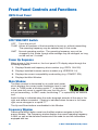
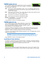
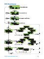
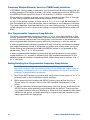
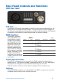
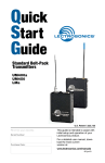
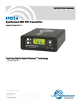
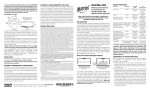
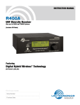
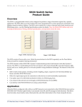
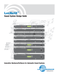
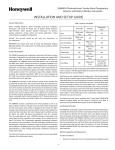
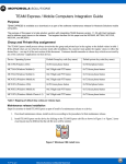
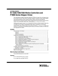
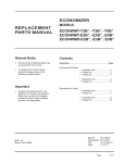
Quick
Start
Guide
IFB Transmitter
IFBT4/E01
U.S. Patent 7,225,135
Fill in for your records:
Serial Number:
This guide is intended to assist with
initial setup and operation of your
Lectrosonics product.
Purchase Date:
For a detailed user manual, download the most current
version at:
www.lectrosonics.com/manuals
06 jun10
Front Panel Controls and Functions
IFBT4 Front Panel
OFF/TUNE/XMIT Switch
OFF
Turns the unit off.
TUNE Allows all functions of the transmitter to be set up, without transmitting.
The operating frequency may be selected only in this mode.
XMIT Normal operating position. The operating frequency may not be
changed in this mode, though other settings may be changed, so long
as the unit isn’t “Locked.”
Power Up Sequence
When power is first turned on, the front panel LCD display steps through the
following sequence.
1. Displays Model and frequency block number (e.g. IFBT4 BLK 25).
2. Displays installed firmware version number (e.g. VERSION 1.0).
3. Displays the current compatibility mode setting (e.g. COMPAT IFB).
4. Displays the Main Window.
Main Window
The Main window is dominated by an audio level meter,
which displays the current audio modulation level in real
time. In TUNE mode, a blinking capital “T” is displayed
in the lower left corner to remind the user that the unit is
not yet transmitting. In XMIT mode, the blinking “T” is replaced by an antenna
icon.
Audio limiting is indicated when the audio bargraph extends all the way to the
right and widens somewhat. Clipping is indicated when the zero in the lower
right corner changes to a capital “C”.
The Up and Down buttons are disabled in this Window.
Frequency Window
Pressing the MENU button once from the Main window navigates to the Frequency window. The Frequency window displays the current operating frequency
in MHz, as well as the standard Lectrosonics hex code for use with transmitters
equipped with hex
2
LECTROSONICS, INC.
switches. Also displayed is the UHF television channel to which the selected
frequency belongs.
In XMIT mode, it is not possible to change the operating frequency.
In TUNE mode, the Up and Down buttons may be used to select a new frequency.
If the TUNING mode is set to NORMAL, the Up and Down buttons navigate in
single channel increments, and MENU+Up and MENU+Down move 16 channels at a time. In any of the various group tuning modes, the currently selected
group identifier is displayed to the left of the hex code, and the Up and Down
buttons navigate among the frequencies in the group. In factory group tuning
modes A thru D, MENU+Up and MENU+Down jump to the highest and lowest
frequencies in the group. In user group tuning modes U and V, MENU+Up and
MENU+Down permit access to frequencies not currently in the group.
Pressing and holding the Up or Down button invokes an autorepeat function, for
faster tuning.
Audio Input Gain Window
Pressing the MENU button once from the Frequency window navigates to the
Audio Input Gain window. This window greatly resembles the Main window, with
the exception that the current audio input gain setting is displayed in the upper left
corner. The Up and Down buttons may be used to alter the setting while reading
the realtime audio meter to determine what setting works best.
The gain range is -18 dB to +24 dB with 0 dB as nominal. The reference for this
control can be changed with the rear panel MODE switches. See page 7 for
more information on the MODE switches.
Setup Window
Pressing the MENU button once from the Audio Input Gain window navigates
to the Setup window. This window contains a menu which permits access to
various setup screens.
Initially the active menu item is EXIT. Pressing the Up and Down keys permits
navigation among the remaining menu items: TUNING, COMPAT and ROLLOFF.
Pressing the MENU button selects the current menu item. Selecting EXIT navigates back to the Main window. Selecting any other item navigates to the associated setup screen.
ROLLOFF Setup Screen
The ROLLOFF setup screen controls the low frequency audio response of the
IFBT4. The 50 Hz setting is the default, and should be used whenever wind
noise, HVAC rumble, traffic noise or other low frequency sounds may degrade
the quality of the audio. The 35 Hz setting may be used in the absence of
adverse conditions, for a fuller bass response.
Press MENU to return to the Setup window.
www.lectrosonics.com
3
COMPAT Setup Screen
The COMPAT setup screen selects the current compatibility mode, for interoperation with various types of receivers.
The available modes are:
IFB - Lectrosonics IFB compatibility mode. This is the default setting and is
the appropriate setting to use with the Lectrosonics IFBR1A or a compatible IFB receiver.
400 - Lectrosonics 400 Series. This mode offers the best audio quality and is
recommended if your receiver supports it.
100 - Lectrosonics 100 Series compatibility mode.
200 - Lectrosonics 200 Series compatibility mode.
MODE 3 and MODE 6 - Compatible with certain
non-Lectrosonics receivers.
Press MENU to return to the Setup window.
TUNING Setup Screen
The TUNING setup screen allows selection of one of four
factory set frequency groups (Groups A through D), two
user programmable frequency groups (Groups U and V)
or the choice to not use groups at all.
In the four factory set frequency groups, eight frequencies per group are
preselected. These frequencies are chosen to be free of intermodulation
products. (Refer to owner’s manual for more information).
In the two user programmable frequency groups, up to 16 frequencies can be
programmed per group.
Note: The TUNING Setup Screen only selects the tuning mode
(NORMAL or Group tuning) and not the operating frequency. Actual
operating frequencies are chosen through the Frequency Window.
Press MENU to return to the Setup window.
Lock/Unlock Panel Buttons
To enable or disable the control panel buttons, navigate to the Main Window
and press and hold the MENU button for about 4 seconds. Continue holding
the button as a progress bar extends across the LCD.
When the bar reaches the right side of the screen, the unit will toggle to the
opposite mode and LOCKED or UNLOCKED will flash briefly on the screen.
4
LECTROSONICS, INC.
IFBT4 Menu Diagram
www.lectrosonics.com
5
Frequency Window Behavior, based on TUNING mode selections
If NORMAL tuning mode is selected, the Up and Down buttons select the operating frequency in single channel (100 kHz) increments and the MENU+Up
and MENU+Down shortcuts tune in 16 channel (1.6 MHz) increments.
There are two classes of group tuning: factory preset groups (Grp A through
D) and user programmable frequency groups (Grp U and V).
In any of the group modes, a lower case a, b, c, d, u or v will be displayed to
the immediate left of the transmitter switch settings in the Frequency window.
The letter identifies the selected factory or user tuning group. If the currently
tuned frequency is not in the current group, this group identification letter will
blink.
User Programmable Frequency Group Behavior
The user programmable frequency groups “u” or “u” work very similarly to the
factory groups with a few exceptions. The most obvious difference is the ability
to add or remove frequencies from the group. Less obvious is the behavior of a
user programmable frequency group with only one entry, or with no entries.
A user programmable frequency group with only one entry continues to display
the single frequency stored in the group no matter how many times the Up or
Down buttons are pressed (provided the MENU button is not pressed at the
same time). The “u” or “v” will not blink.
A user programmable frequency group with no entries reverts to non-groupmode behavior, i.e., access is allowed to all 256 available frequencies in the
selected receiver module’s frequency block. When there are no entries, the “u”
or “v” will blink.
Adding/Deleting User Programmable Frequency Group Entries
Note: Each User Programmable Frequency Group (“u” or “v”) has
separate contents. We recommend that you consider the larger issue of
frequency coordination prior to adding frequencies in order to minimize
potential intermodulation problems.
1. Start from the Frequency window and verify that a lower case “u” or “v” is
present next to the transmitter switch settings.
2. While pressing and holding the MENU button press either the Up or
Down button to move to one of the 256 available frequencies in the
block.
3. To add or remove the displayed frequency from the group, hold down the
MENU button while pressing and holding the Up button. The group tuning mode indicator will stop blinking to show that the frequency has been
added to the group, or begin blinking to indicate that the frequency has
been removed from the group.
6
LECTROSONICS, INC.
Rear Panel Controls and Functions
IFBT4 Rear Panel
XLR Jack
A standard XLR female jack accepts a variety of input sources depending on the
setting of the rear panel MODE switches. XLR pin functions can be changed to
suit the source depending on the positions of the individual switches. For detailed
information on the setting of these switches see the owner’s manual.
MODE Switches
The MODE switches
allow the IFBT4 to accommodate a variety
of input source levels
by changing the input
sensitivity and the pin
functions of the input
XLR jack. Marked on
the rear panel are the
most common settings.
Each setting is detailed
below. Switches 1 and
2 adjust the XLR pin
functions while switches
3 and 4 adjust the input
sensitivity.
Name
Switch
Positions
1 2 3 4
XLR Pins
Balanced
qqqp CC
Input
Sensitivity
3 = Audio
1 = Common
No
-10 dBu
MIC p p p q 2 = Hi
3 = Lo
1 = Common
Yes
-42 dBu
LINE p p q q 2 = Hi
3 = Lo
1 = Common
Yes
0 dBu
RTS1 p q q q 2 = Hi
1 = Common
No
0 dBu
RTS2 q q q q 3 = Hi
1 = Common
No
0 dBu
Power Input Connector
The IFBT4 is designed to be used with the CH20 external (or equivalent)
power source. The nominal voltage to operate the unit is 12 VDC, although it
will operate at voltages as low as 6 VDC and as high as 18 VDC.
External power sources must be able to supply 200 mA continuously.
Antenna
The ANTENNA connector is a standard 50 ohm BNC connector for use with
standard coaxial cabling and remote antennas.
www.lectrosonics.com
7
8
LECTROSONICS, INC.
www.lectrosonics.com
9
10
LECTROSONICS, INC.
www.lectrosonics.com
11