1
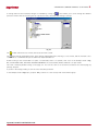
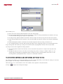
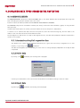
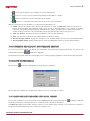
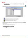
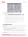
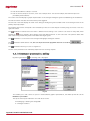
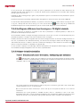
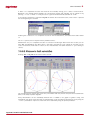
SIPCON / P Protection and Automatic Functions Console User manual IB1014FA Rev : E (10/10) © All rights reserved. No part of this publication may be reproduced by whatever means, without the prior written permission of Ingeteam T&D. Ingeteam T&D reserves the right to make any changes without prior notice. INDEX 1. INTRODUCTION.......................................................................................................................................................4 1.1 Functional aspects .............................................................................................................................................4 1.2 Buttons used in the application ...........................................................................................................................4 1.3 Access ..............................................................................................................................................................5 2. VIEWS ORGANIZATION ............................................................................................................................................7 3. MAIN VIEW. COMMON ELEMENTS TO ALL VIEWS ..................................................................................................... 8 4. MONITORING, COMMANDS, ACTIVE TABLE ............................................................................................................ 10 4.1 Monitoring.......................................................................................................................................................10 4.1.1 Status ....................................................................................................................................................10 4.1.2 Statistical data .......................................................................................................................................10 4.1.3 Measurements ........................................................................................................................................10 4.2 Commands ......................................................................................................................................................10 4.3 Active table .....................................................................................................................................................11 5. SETTINGS .............................................................................................................................................................12 5.1 5.2 5.3 5.4 5.5 5.6 5.7 5.8 General description of the settings view. PC settings and relay settings .................................................................. 12 Types of settings. Validating settings. Default values............................................................................................ 12 Settings tables .................................................................................................................................................13 Request settings. Display differences ................................................................................................................. 14 How to send settings ........................................................................................................................................15 How to accept settings .....................................................................................................................................16 Pattern and setting tables management .............................................................................................................. 16 Printing settings and exporting settings to file ..................................................................................................... 17 5.8.1 Settings print format ...............................................................................................................................18 5.9 Views with individual characteristics .................................................................................................................. 19 5.9.1 View Configuration for Digital Inputs, Digital Outputs and Leds .................................................................... 19 5.9.2 Events Mask View....................................................................................................................................19 5.9.3 Control Measurements Selection View ....................................................................................................... 20 5.9.4 Signal Programming View .........................................................................................................................20 6. DISPLAYING DATA TYPES STORED IN THE PROTECTION......................................................................................... 22 6.1 Common elements ...........................................................................................................................................22 6.1.1 Automatic and explicit request for data ..................................................................................................... 22 6.1.2 Delete data .............................................................................................................................................22 6.1.3 Export data .............................................................................................................................................22 6.2 Events ............................................................................................................................................................23 6.3 Faults .............................................................................................................................................................23 6.4 Measurement chronological report ..................................................................................................................... 23 7. DISTURBANCES ....................................................................................................................................................24 7.1 7.2 7.3 7.4 7.5 7.6 7.7 7.8 7.9 Functional aspects ...........................................................................................................................................24 Setting to configure the oscillogram ................................................................................................................... 24 Disturbances list ..............................................................................................................................................24 Automatic and explicit disturbance request......................................................................................................... 25 Delete disturbances..........................................................................................................................................25 Transform disturbances into ASCII format........................................................................................................... 25 Exchange disturbances via diskette. Import disturbances in COMTRADE format. .................................................... 26 Configuring the fault locator ..............................................................................................................................26 Displaying disturbances ....................................................................................................................................27 7.9.1 Disturbance presentation. Editing ............................................................................................................. 28 7.9.2 Disturbance long and short descriptions (texts). Editing. ............................................................................. 29 7.9.3 Management of the disturbance presentations............................................................................................ 29 7.9.4 Oscillograms with more than 8 analogue or 16 digital channels ................................................................... 30 7.9.5 Distance to fault calculation ..................................................................................................................... 30 Ingeteam Transmission & Distribution S.A. IB1014FA/D III 0BINTRODUCTION 1. INTRODUCTION This manual describes the protection visualization and setting possibilities provided by the SIPCON Console. The terms ‘Relay’ and ‘Protection’ are used indifferently in this manual. Este programa ha sido desarrollado para la plataforma WIN32, lo que quiere decir que funciona en aquellos sistemas operativos Windows de 32 bits. This program has been developped for the WIN32 platform, so it works on 32 bits Windows operating systems. 1.1 FUNCTIONAL ASPECTS Inside the SIPCON Console application the part dedicated to protections enables the following functions: Continuous monitoring of data being collected by the protection (Status, Measurements and Statistical Data). Reading and writing of protection settings. Terms such as Request and send or update can also be used. Request and display of events collected and stored in the protection (Faults, Events, Historical Record of Measurements and Disturbances). 1.2 BUTTONS USED IN THE APPLICATION The actions contained in the programme are generally implemented by clicking on the buttons with the mouse. The following table gives a description of each of these buttons, what they look like, the actions they carry out and the chapter describing the action. Ingeteam Transmission & Distribution S.A. IB1014FA/D 4 0BINTRODUCTION Button Actions Chapters - Exit of the application 3 - Move between different views - Move between different faults - Move between different views - See differences in settings - Go to next table of settings 3 6.3 3 5.4 5.3 - Go to previous table of settings 5.3 5.4 6.1.1 - Request of settings - Explicit request for data (Faults, Events and Current historical record) - Explicit request for disturbances , 7.4 - See differences in settings 5.4 - Send settings 5.5 - Accept settings 5.6 - Management of patterns and tables of settings 5.7 - Print settings and download settings to file 5.8 - Delete data - Delete disturbances 6.1.2 7.5 - Export data 6.1.3 - Change disturbances into ASCII format 7.6 - Exchange disturbances via diskette 7.7 - fault locator configurator 7.8 - Move cursor while displaying disturbances 7.9 - Scale background for each wave 7.9 - Edit disturbance presentation 7.9.1 - Edit disturbance description texts 7.9.2 - Manage disturbance presentations 7.9.3 - Move to the previous o next presentation. 7.9.4 - Distance to fault calculation 7.9.5 - DFT (Discrete Fourier Transformation) calculation. 7.9.5.3 1.3 ACCESS Access to the protections can be gained through ‘OPERATION’, from the SIPCON Console main menu, which is also called the MASTER program. This may be done either entering through SUPERVISION or PROTECTIONS, by pressing the corresponding buttons: Clicking on the button, how the console behaves will depend upon the value of the configuration variable “Protection device communication mode” located in the communications page. (See “Console configuration manual”) If the variable value is “Configured device” the following dialogue appears which enables us to select the unit (protection or automatic sequence) we desire amongst those available. Ingeteam Transmission & Distribution S.A. IB1014FA/D 5 0BINTRODUCTION Fig 1.2 If the value of this variable is “Autodetection” the SIPCON Console tries to detect the protection model it is communicating with according to the description given in the “PROTECTION CONFIGURER” chapter of the user instruction manual. If not, we will return to the Fig. 1.1 view, or otherwise a view similar to Fig. 1.2 is displayed, but with a single position and only one unit, corresponding to the position and unit detected. If the value of this variable is “Not specified”, when the “PROTECCTIONS” button is clicked the programme will ask us whether we want to work in “Configured device” or “Autodetection” mode. Once the answer has been given it is stored away, so that the question is not asked again unless we select this option again from the communications configuration page. Clicking on the manual): button we enter the supervision function, which may contain (See console CAD user A protection access symbol (icon) displayed on the Fig 1.2 view An access symbol (icon) to a specific protection. These symbols (icons), give you access to the list of protections or to one specific protection Ingeteam Transmission & Distribution S.A. IB1014FA/D 6 1BVIEWS ORGANIZATION 2. VIEWS ORGANIZATION Each protection is characterised by a set of views displaying the data of the protection. A protection may share certain views with other protections, and also contain views specific to itself. The views are organised according to sets of views and independent views, which operate in a similar manner in certain aspects. A set of views is made up of several related views and which are displayed in order as defined by the application, and not by the protection. The sets of views are: Monitoring: STATUS MEASUREMENTS STATISTICAL DATA SETTINGS The independent views are: Events FAULTS EVENTS HISTORICAL RECORD OF MEASUREMENTS DISTURBANCES Monitoring includes three sets of views STATUS, MEASUREMENTS AND STATISTICAL DATA, on which, via a communication link, the information is displayed and updated every three seconds. This information is sent to the protection when required, but is neither stored in the protection nor the PC. “SETTINGS” is a set of views enabling you to read and write (request and send) settings to the protection. The settings are stored in the protection and PC. Events contains four independent views where events stored in the protection can be queried and then sent to the PC automatically or at the user’s request. One specific protection can contain any amount of views from any set and any amount of independent views, albeit all protections have SETTINGS, almost all have STATUS and many contain views from every set and every independent view. Ingeteam Transmission & Distribution S.A. IB1014FA/D 7 2BMAIN VIEW. COMMON ELEMENTS TO ALL VIEWS 3. MAIN VIEW. COMMON ELEMENTS TO ALL VIEWS By pressing ‘select’ on the Fig. 1.2 view or double-clicking upon the unit required, we access the unit (protection or automatic functions); the following describes the protections only. Amongst all the views contained in the protection, the first independent view is entered or the first view of a group of views according to the order in the list below: STATUS SETTINGS EVENTS FAULTS HISTORICAL RECORDS (DATA) STATISTICAL DATA MEASUREMENTS DISTURBANCES That is, if a status exists, the status view one is accessed, etc… The following describes the elements common to every view: Line 1 Field 1: Utility (“Elorrio”) Field 2: Electrical bay or UCL (“Line 4”) Field 3: Model-Manufacturer (“PL250-*20*1BUA5*/F – XXXXXXXXXXXX”) Field 4: Date (“15/06/99”) Field 5: Time (“16:03:85”) Line 2 Field 1: If it belongs to a set of views, group text (“STATUS”); if it is an independent view, view text (“FAULTS”, “EVENTS”, etc.). Field 2: If it belongs to a set of views, view text (“Protection”); if it is an independent view, it is left alone. Field 3: If it belongs to the SETTINGS set of views, information regarding the tables of settings (See 6.2); if otherwise, leave empty. Field 4: Information regarding communications status (“En Comunica”). This varies according to the different communications. Field 5°: If it belongs to a set of views, the relative position of the view in the set (“1st of 5”); if it is an independent view it indicates the total amount of events, (FAULTS, EVENTS, etc…) collected in the protection. Lower buttons , is used to go to the first, previous, next or last view in one set, only for views belonging to a set, following the natural order of the set; it is not displayed in the other views. Also for the independent FAULTS view, it enables you to go to the first, previous, next or last fault. , is used to exit from the protection section. , is used for moving through the different independent and sets of views, and also enables you to scroll through the tables of settings. It also provides information regarding imported settings and the differences between protection settings and those stored in the PC. (See 6.3) Ingeteam Transmission & Distribution S.A. IB1014FA/D 8 2BMAIN VIEW. COMMON ELEMENTS TO ALL VIEWS If settings have not been retrieved, dialogue is extended by clicking on , this enables you to scroll through the different protection views as well as inspecting the set of protection views, and other data relating to settings. Fig 3.1 The folders indicate the set of views, with the set text next to them. The pages indicate the different views. These may be independent views or belong to a set of views, and the view text is also located next to it. SETTINGS are special and will be explained further on. Double-clicking on the closed folder icon opens a closed folder, and if it is opened, it will close. In the example shown in Fig. 3.1, STATISTICAL DATA, SETTINGS and MEASUREMENTS are closed folders, whereas STATUS is an open folder. This view is exited by double-clicking on the page icon. You can also move on to the view associated to the selected page by pressing ‘Aceptar’. If you are in the settings folder, you can also select the table you desire. In the example shown in Fig 3.1, if you press ‘OK’ you move on to the ‘last trip view of the STATUS group. Ingeteam Transmission & Distribution S.A. IB1014FA/D 9 3BMONITORING, COMMANDS, ACTIVE TABLE 4. MONITORING, COMMANDS, ACTIVE TABLE 4.1 MONITORING A monitoring is a set of views, which when entered and in communication, data is requested and updated automatically at fixed time intervals (every three seconds). This is instantaneous information, it is stored neither in the protection nor the PC. The set of STATUS, STATISTICAL DATA and MEASUREMENTS views can be monitored. Furthermore, from some of those views, commands can be sent, and active table number can be changed or requested. 4.1.1 Status As well as the fixed part of the view, it displays several elements that are updated with the communication; these are number squares as the one next to the word ‘Maximeter’. There are also leds, such as those located next to the ‘Protection on line” text. There are other elements that are displayed on the view and are not active, such as the numerical square next to ‘Neutral’ or the led located next to ‘Manual lock”. In that case both the element and the associated text appears in grey. These are elements that do not form part of this protection, but may be part of other protections. The squares with a white text and red background and the isolated white texts on a blue background refer to a group of interrelated elements. There is also a set of command buttons that will be explained further on. 4.1.2 Statistical data All of the information explained for STATUS views is valid for STATISTICAL DATA views, albeit this view only displays numerical elements and all are active. It contains three command buttons. 4.1.3 Measurements It doesn’t contain any led type elements. There are twelve deactivated numerical squares and no command buttons. 4.2 COMMANDS The black text and grey background buttons execute commands; i.e. they indicate the protection to carry out a specific action. Furthermore, the action to be carried out is associated to the closest monitoring element. refers to the maximeter next to it, and when pressed it tells the protection to set the maximeter to For example, zero, which is displayed when the view is updated. In the same way, and activate and deactivate the recloser, and this is displayed on the leds “On line” and “Locked” when the view is updated the next communication. The button sends the time to the protection. In the case shown below, the time is asked via a dialogue. Once the desired time and date have been entered, by clicking on ‘OK’, the new time is sent to the protection and is updated in the corresponding field. Ingeteam Transmission & Distribution S.A. IB1014FA/D 10 3BMONITORING, COMMANDS, ACTIVE TABLE This is the only command requiring additional information. The two “Reset” and “Initial value reset” buttons also generate commands on the STATISTICAL DATA view. The STATUS, STATISTICAL DATA and MEASUREMENTS views also contain other command buttons. 4.3 ACTIVE TABLE (See 5.3) The action of requesting or sending the active table number is similar to the commands ones. In it the following square is displayed, which contains the elements described below: A square indicating the total number of setting tables contained in the protection. The number, in this case 3, is written in white with a blue background and cannot be modified. A square where we write the number of the table we wish to send to the protection so that it can be considered an active table, on the right-hand side. In this case 1. A square indicating the number of the table that the protection sends as the active table number, on the left-hand side. In this case 1. A pushbutton for sending, and then automatically requesting the active table number, located on the right-hand side. A pushbutton for requesting the number of the active table, located on the left-hand side. Upon entering the view the value of the active table number stored in the hard disc is placed on the right-hand side and an active table number is requested in order to place it on the left-hand side. If a discrepancy exists a message is displayed. The ‘Send’ pushbutton sends the active table number, and the active table number is automatically requested, and if it is received is then placed on the left-hand side, with a warning if any discrepancies arise. Ingeteam Transmission & Distribution S.A. IB1014FA/D 11 4BSETTINGS 5. SETTINGS 5.1 GENERAL DESCRIPTION OF THE SETTINGS VIEW. PC SETTINGS AND RELAY SETTINGS Settings have two main differences compared to the monitoring data: Two sets of settings can be displayed, those stored and edited in the PC and those requested from the Relay. The objective of the two sets of settings is to edit, save and exchange the PC settings as we wish, and if necessary compare them with the Relay settings. In short, to facilitate the relay programming process. The Relay settings are not continuously updated, the user asks for them when required. Based upon the information read in the protection identification file (xxxxxxxx fip), which is set when the protection is selected in the engineering process, this determines what setting views are displayed and what settings they contain. (the grey background) indicates a setting that is located in the protection according to the protection identification file, and (the green background) indicates a setting that is not located in the protection according to the protection identification file. Each setting has a double space, one on the right-hand side for the PC and another on the left-hand side for the Relay. Referring exclusively to the settings that are located in the protection according to the xxxxxxxx.fip file, the PC values are always present, but the Relay values may not be if they have not been received yet via the communications link. The squares with white texts on a red background and isolated white texts on a blue background refer to a group of interrelated elements. 5.2 TYPES OF SETTINGS. VALIDATING SETTINGS. DEFAULT VALUES There are different types of settings: Numerical without decimals These are numbers without decimals. They have a minimum and maximum value (range). Three valid examples of numerical settings without decimals are 25, 0, 0012 Values should be edited according to their format. Numerical with decimals These are numbers containing decimals. They have a minimum and maximum value (range). Three valid examples of numerical settings containing decimals are 10.2, 0.0, 13, .5 Values should be edited according to their format. Options Known as option settings. Each option is represented by a written text. For example, Yes-No, Direct-Inverse, Voltage-Current-Energy-Power The programme displays the options to select and prevents format errors. Ingeteam Transmission & Distribution S.A. IB1014FA/D 12 4BSETTINGS Other settings There are other more specific settings such as input, output and leds configurations, events masks and oscillo configuration, which from the operating point of view are similar to option settings; i.e. the programme displays the options to select and prevents format errors. Another important aspect is setting validation. Numerical type settings should comply with a format and range. The user is free to edit them, after which the programme checks the setting for format and range compliance. The range of a specific setting is characteristic to each protection, and the format depends exclusively upon the type of setting, as mentioned above. For numerical type settings the programme checks the setting validity, its format as well as range, if an error exists it sends a message that helps to correct it, whether it is due to the format or the range. The setting validation process is carried out globally for an entire view that may have been edited. The programme interrupts the validation process when it detects the first format error, if it exists, and places the cursor (focus) upon the non-valid setting. Setting validation occurs when the user executes any type of global action, whether moving views or implementing actions. This means that the validation of settings on a view is carried out every time a user clicks on any of the buttons located in the lower part. Initially, default values are assigned to a protection setting, so that to numerical settings the lowest possible value is given, and to option settings the first option. 5.3 SETTINGS TABLES (See 4.3) In general, it may be of interest to programme the protection differently, depending upon the circumstances required. This programming process may not require each and every setting being edited, but rather a simple selection of a group of values for the settings. In order to carry out this process the settings are organised in tables. A specific setting may have one single value regardless the table we are in, in this case it is called a single table or table zero or it may have a different value according to the table we are in, in this case it is said to belong to several tables. The amount of tables is a specific characteristic of the protection. Each table represents the protection’s operating mode. Pushbuttons and enable you to display or edit the settings in the next or previous table respectively. Chapter 4.3 describes how to activate a specific table, meaning that the protection considers the settings in that table as valid when starting operation. As pointed out in chapter 3, on line 2 – field 3 provides all the information regarding setting tables and active tables. provides you with the following information: In general, blue colour is associated to the settings of several tables, and black to the single table settings. All the settings are blue; therefore they belong to several tables. A view does not frequently mix the settings from several tables with those of a single table, although it may occur. T0, in black colour, means that the protection contains settings belonging to table zero. T1 T2 T3, in blue, means that the protection contains settings from several tables and the number of tables is 3. The blue line around T1 T2 T3 means the view we are in contains settings from several tables. No black line around T0 means it contains no settings from the single table. T1, white on a blue background, means that the PC settings being displayed and edited belong to table 1 (Obviously, for those settings belonging to several tables). Ingeteam Transmission & Distribution S.A. IB1014FA/D 13 4BSETTINGS The red line under the T1 icon means that the active table for the settings from several tables is table 1. Chapter 5.3 explains how to change the active table number. Here is another example: means that the protection contains settings from the single table and several tables; the settings from several tables have three tables; the current table contains settings from the single table but none from the several tables; table 2 is the active table; the settings from the PC being displayed and edited, that belong to several tables, belong to table 3, none in this case, given that we are being informed that there are no settings from several tables on this view. 5.4 REQUEST SETTINGS. DISPLAY DIFFERENCES Pushbutton enables you to request the protection for all the settings; that is, every table from every view. The settings are displayed under , indicating those that are different in the protection and the PC with a red dot If every setting is received, the following messages are displayed: EVERY setting received. Differences between RELAY and PC. or EVERY setting received. No differences between RELAY and PC. Depending upon whether there are differences between the PC settings and protection settings or not. If every setting is not received, the following message is displayed: Reception of settings pending. Settings cannot be sent until every setting has been received. By pressing the pushbutton several times you can browse through the differences between the Relay settings and the PC settings. This is done by browsing through the pages containing differences and then, on each page, the tables containing differences. It operates as a loop; that is, you return to the initial view and table. If no differences exist, the following message is displayed: No differences. In order to obtain a global view of where the differences are located, by pressing a view such as the one below appears: Ingeteam Transmission & Distribution S.A. IB1014FA/D 14 4BSETTINGS Which as well as enabling us to browse through the system of views and tables (See 3) also provides other information regarding settings: Pages: means that there are no settings for the corresponding table (vertical) and view (horizontal). For example, on the ‘Overcurrent Protection” view (1)’, table T0 there is a settings. which indicates that this view contains no single table means that there are settings but they have not been retrieved. (blue dot) means that there are settings, they have been retrieved and no differences exist. (dark red dot) means there are settings, they have been retrieved, differences exist and have been checked. (red dot) means there are settings, they have been retrieved, differences exist but have not been checked. Folders: (red dot) is displayed if a difference exists and has not been visited, otherwise, (dark red dot) is displayed if a difference exists, otherwise, (blue dot) is displayed if a setting has been retrieved; otherwise, is displayed if any other case arises; that is, if no setting has been retrieved. In short, the settings folder displays the information of most interest for the user. 5.5 HOW TO SEND SETTINGS Settings may only be sent if ALL the Relay settings have been received. By clicking on you accept the settings in the PC as correct. These settings are then written in the Relay, as follows: All settings contained on the PC side are recorded on the hard disc. Those settings that are different in the PC and in the Relay are sent to the Relay. Wait 4 seconds for the Relay to accept (record) the settings that have been sent. Request Relay for all the settings. The Relay and PC settings are compared, and if a there is a difference, a message indicating this is then written out. Ingeteam Transmission & Distribution S.A. IB1014FA/D 15 4BSETTINGS 5.6 HOW TO ACCEPT SETTINGS The Accept settings process compensates the Send settings. When accepting settings, you must bear in mind that these can only be accepted if ALL the Relay settings have been received beforehand. On the other hand, the Relay may have sent settings out of range (lower than the minimum or higher than the maximum value) or illegal settings (do not adhere to the expected format). means that we accept the settings contained in the Relay as correct, and these are then written in the PC. This Pressing is done as follows: The settings contained on the Relay side are copied onto the PC side, except the out of range settings that are set to range, and the illegal settings that are not copied. The settings now contained on the PC side are recorded on the hard disc. If the Relay side contains illegal settings the following warning is issued: Unknown and illegal settings have NOT been recorded. Otherwise the following message is issued: All settings retrieved from the RELAY have been recorded on disc. 5.7 PATTERN AND SETTING TABLES MANAGEMENT Patterns is the name given to the group of all settings contained in a protection, that is, all of the tables of settings of all the views. The pattern and setting tables management function is to avoid having to insert repeatedly settings patterns that, in general, may look similar. This function enables the setting patterns to be saved to and retrieved from the hard disc, and exchanged between different protections, utilities or PCs via diskette. It also enables the copying of setting tables contained in a protection over other tables, given that the tables are frequently quite similar. By pressing the pushbutton on any setting view, the following dialogue is displayed Ingeteam Transmission & Distribution S.A. IB1014FA/D 16 4BSETTINGS which enables you to: Edit a text for the settings pattern displayed on the view (PC Settings). Copy the settings pattern from the view onto the hard disc or retrieve a settings standard from the hard disc and copy it on the view (PC Settings), by using the two upper arrows. Exchange settings patterns between the hard disc and any storage disc drive by using the two lower vertical arrows. Delete settings patterns from the hard disc or the selected storage disc drive by clicking on the respective wastepaper icons. Read and display the patterns contained in the selected storage disc drive by clicking on the drive icon. The “Available patterns” disc drive and the directory (folder) can be changed by clicking on the opened folder button. Copy a setting table over another, by clicking on the horizontal arrow; the programme indicates ‘’ the copies made. Two things must be said as regards the settings patterns: The settings patterns stored in the hard disc can be accessed from all protections in every electric bay and all PC facilities. Although two protections do not coincide as to the settings they contain, or range, or number of tables, etc., the settings may be exchanged. The programme extracts information from the original patterns and copies it on the receiving patterns, putting default values in the place of unavailable information. 5.8 PRINTING SETTINGS AND EXPORTING SETTINGS TO FILE By clicking on the printer icon on any view enables you to print or export (download), in text mode, the settings of a selected group of pages or all the settings contained in the protection on to a file. When printing it out, a ‘serial number’ can also be included so that it appears on the printed sheets. Clicking on displays the following view dialogue Ingeteam Transmission & Distribution S.A. IB1014FA/D 17 4BSETTINGS The action to carry out can be print settings or send To file. If the action is to print, a serial number may be introduced in order to identify the specific protection that is being used. pushbutton enables you to select any If the action is to send to file, a file in which to write is suggested, and the other. Whatever the action is to be taken, it may be a Selection of pages or All pages. If the option chosen is Selection, the selected action is carried out on the pages selected in the ‘Select pages’ list, which contains the texts of all the protection settings pages. 5.8.1 Settings print format Settings are printed according to the following format: Every page has a heading with a text including the Installation, Position, Device, Serial number and Manufacturer. Every page has a ‘List of settings’, with a footnote containing the date, time and page number. Every page contains as many pages of settings as it can fit, with a centred and outlined page heading, followed by the settings. The setting text and value is extracted from each setting, and the range also, if the setting has a range. A page format is approximately as the shown below: Installation: Elorrio Position: UCL 1 Device: PL250*18*1AEB0*/B - (ED2011B) Manufacturer: XXXXXXXXXXXX _______________________________________________________________________ Breaker Supervision ------------------Breaker Supervision Breaker Supervision___________________________________T1 T2 T3 Excessive number of trips.......:::................... 4 1 1 min max 1 254 inc 1 Ingeteam Transmission & Distribution S.A. IB1014FA/D 18 4BSETTINGS Time span for counting the excessive number of trips..3600 300 300 300 3600 Cumulative kI2 alarm for maintenance.................. 5 0 0 0 65535 1 Cumulative kI2 start value (setting).................. 0 0 0 0 65535 1 Enable trip circuit supervision...................... YES YES YES Enable closing circuit supervision................... YES YES YES 1 Breaker operation logic ----------------------Operation logic scheme Breaker_____________________________________________ T1 T2 T3 Trip locking........................................ NO NO NO min max inc Open failure timing................................ 5.00 0.10 0.10 0.10 5.00 0.01 Closing failure timing............................. 5.00 0.10 0.10 0.10 5.00 0.01 __________________________________________________________________________________________ List of settings 22/06/99 16:55 Page 1 The to file settings format is similar to the printed format, without the foot note information. 5.9 VIEWS WITH INDIVIDUAL CHARACTERISTICS The view shown in Fig 5.1 can be considered a standard view; but there are also several views that operate and behave differently, as described below. 5.9.1 View Configuration for Digital Inputs, Digital Outputs and Leds These views enable you to assign logic Inputs, Outputs or Leds to the physical Inputs, Outputs or Leds. In the ‘DIGITAL INPUTS CONFIGURATION’ square there are two windows for configuring digital inputs. It shows the available digital inputs on the left-hand side, also called logical digital inputs. The right hand side shows the physical digital inputs; that is, those really contained in the protection, 15 in this case. The ‘=>’ pushbutton associates the selected logical digital input on the left to the selected physical digital input on the right. There are also analogue views for digital outputs and leds, called ‘ Digital Outputs Configuration’ and ‘Configure Leds’. 5.9.2 Events Mask View This view enables the programming of event appearance and inhibition in the protection. The masks are organised according to registers, each register as well as each register mask contains a written text. The register texts are located on the left-hand side, the ‘Communication’ register is selected in this case; the letter ‘C’ on the right-hand side indicates that it is a procome-compatible register, and a letter ‘P’ would indicate a private register. The register selected on the left has its associated events on the right, so that the event can be inhibited by changing the corresponding mask to ‘Yes’ or not inhibited by changing it to ‘No’. In order to do this the pushbuttons available in ‘Modify Masks’ are used. The left-hand side pushbutton indicates the mask the action will affect to. The possible values are the following ones: Ingeteam Transmission & Distribution S.A. IB1014FA/D 19 4BSETTINGS ‘MASK’, placed over the mask selected on the right-hand side. ‘RECORD’, placed over all the selected register masks on the left-hand side. ‘ANY’, placed over all the masks in all the registers. The centre pushbutton enables the inhibition (‘Yes’) or non-inhibition (‘NO’) of the event(s) acted upon. The ‘ok’ pushbutton implements the action chosen upon the selected elements. 5.9.3 Control Measurements Selection View This view informs the protection about what measurements and IN what order they will be sent in control. A maximum of 64 measurements can be sent and each one may be repeated. The left-and side window indicates the available measurements. The right-hand side window indicates the measurements that are sent and in what order. The pushbuttons on the lower right side enable the following: ‘Insert’, inserts the measurement selected on the left in the space selected on the right; the measurement selected on the right and those below move down one space. ‘Add’ adds the measurement selected on the left to the end of the list on the right. ‘Copy’ replaces the measurement selected on the right by the measurement selected on the left. ‘Delete’ deletes the measurement selected on the right. 5.9.4 Signal Programming View The special characteristic of this view is that the setting can only be displayed according to Relay or according to PC, not both simultaneously. This view enables complex digital signals to be generated from: NOT, AND and OR logical operations among the basic digital signals (“Available Signals” in figure) Timing (delay and duration of signal) The programming and use of these signals is optional. Examples of basic digital signals are as follows: Instantaneous phase trip (50) Phase time unit trip (51) Neutral time unit trip (51N) Overvoltage time unit trip (27) Status of (physical) digital input 1 ………………….. Status of (physical) digital input 15 A logical signal may be used as an input to define another logical signal or even itself. It may also be assigned to a physical relay on the Outputs Configuration view, or to an led on the Leds Configuration view. The aforementioned means that the same written texts displayed on the ‘Logical signal’ list will appear on ‘Available signals’ list, as well as on the ‘Available digital outputs’ and ‘Available leds’ lists on those digital outputs and leds views equivalent to Fig 5.3. The amount of programmable signals (6 in this case) and the amount of signals that can be entered in the OR and AND spaces (8 and 8 in this case) may vary from one unit to another. A signal may be denied, and a circle on the right-hand side of the list displays it. The pushbuttons in the OR and AND spaces operate as follows: Ingeteam Transmission & Distribution S.A. IB1014FA/D 20 4BSETTINGS enables you to add a new signal at the end of the list if there is room. deletes the signal selected from the list. reverses the signal selected from the list. Furthermore, the icons display the setting according to the PC or RELAY, if it has arrived. As shown in Fig 5.4, the OR and AND gates are fixed, these are then followed by an AND/OR gate, followed by a delay in the pulse start up and pulse width. The pulse delay and pulse width ranges are unit dependent. If the pulse length is indicated ‘By logic’ it remains on one after activation, as long as the conditions are maintained; otherwise the programmed set time is kept. Ingeteam Transmission & Distribution S.A. IB1014FA/D 21 5BDISPLAYING DATA TYPES STORED IN THE PROTECTION 6. DISPLAYING DATA TYPES STORED IN THE PROTECTION 6.1 COMMON ELEMENTS The independent views correspond to different incidents; that is, lists where different data are displayed, which may have been collected by the protection and then sent to the console. Possible incidents are FAULTS, EVENTS and HISTORICAL MEASUREMENTS RECORDS. DISTURBANCES may also be considered as incidents, but as they contain much more information, graphs, etc. they are dealt with specifically. Incidents have several aspects in common, and each incident also has its own specific characteristics. It contains a list of elements with data collected in the protection, these are listed chronologically, from the oldest to the newest. In this case these are historical measurements records. The tree diagram icon and the exit icon carry out their regular functions; the other three pushbuttons represent characteristics common to all incidents. 6.1.1 Automatic and explicit request for data The different sets of data may be requested automatically at a given time (see facility configuration file in user manual), or by clicking on the pushbutton. The data received updates the corresponding list on the view if it is being displayed, independent of the way the data is requested. 6.1.2 Delete data By clicking on the pushbutton, the following view is displayed: It allows you to delete data ( in this case historical measurement record data) according to selection or date. 6.1.3 Export data By pressing the pushbutton the following view is displayed: Ingeteam Transmission & Distribution S.A. IB1014FA/D 22 5BDISPLAYING DATA TYPES STORED IN THE PROTECTION It enables the user to select a format, by adding or replacing records (data) that may already be contained in the file, and export the data to the ASCII file using Records selected or From date 1 to date 2. This means the data can be imported from a spreadsheet, database, etc… 6.2 EVENTS By clicking on the pushbutton and selecting ‘events’ the events view is displayed. It contains a main list, the one on top, which displays the events according to dates, the most recent event at the end. The written description of the event is located on the right-hand side of the date. The lower window contains additional data associated to the selected event. 6.3 FAULTS By clicking on the pushbutton and selecting ‘faults’ the faults view is displayed. It contains a list displaying the faults according to dates, the most recent at the end. The four-column format on the righthand side (duration, type of fault, type of trip, open current) is common to all faults. By double clicking on a fault the fault view is displayed: The format of this view depends upon the type of fault (fault profile); by clicking on the “Index” pushbutton the user returns to the previous view, and the pushbuttons enable the user to move through the different faults. 6.4 MEASUREMENT CHRONOLOGICAL REPORT The list contains the measurements according to dates, the most recent at the end. The four-column format located on the right-hand side, depends upon the type of historical measurements record (profile). Ingeteam Transmission & Distribution S.A. IB1014FA/D 23 6BDISTURBANCES 7. DISTURBANCES 7.1 FUNCTIONAL ASPECTS The Protection Console stores the disturbances collected according to the COMTRADE format, which is a standard storage sample. This enables the user to import, display and export disturbances written in this format. The disturbance functions are as follows: Graphic representation including scaling facilities (timing and size). Defining and managing the different graph display modes (presentations). Printing the graph. Different disturbance calculations associate to the disturbance, particularly the distance to fault calculation. Exchanging disturbances between different protections, utilities or PCs by means of diskettes. Another function is the Disturbance Backup. It is part of the SIPCON Console, but as a separate application, and is therefore not described in this manual. The disturbance backup function is accessed through the main menu by clicking on the ‘OSCILLOGRAMSS’ pushbutton. (See ‘OSCILLOGRAM BACKUP’ in the ‘INTEGRATED PROTECTION AND CONTROL SYSTEM’ user manual). 7.2 SETTING TO CONFIGURE THE OSCILLOGRAM The oscillogram can be picked up by means of the upwards side of any signal belonging to the protection device. In order to configure the oscillogram the user must enter the view corresponding to its settings by means of the protection console tree diagram , and selecting the “Oscillograph record configuration ” view. Once inside the view two windows with written descriptions are displayed. The window on the left displays the digital signals that may be programmed as a cause for the oscillo device pickup o they may be selected for recording in the disturbance. In order to select a signal as the cause for the oscillogram pickup, click on the cursor. On the right column (P) the status of the signal will change from N to Y and vice versa. pushbutton using the In order to assign a signal as a digital channel to be recorded during the disturbance, select the signal to store from the lefthand side window and select the channel to register the signal on from the right-hand side window. Then, by clicking on the pushbutton, the selected signal transfers to the right-and side window and can then be sent to the relay. In order to remove a digital channel from the register list, select it from the right-hand side window and then click on the pushbutton. 7.3 DISTURBANCES LIST This view provides the following information: -‘The list of disturbances recorded by the protection’ in which the disturbances are arranged according to their date and time, so that the most recent one is located at the end. A short description of the disturbance is also displayed. This description is created by default with the information of the disturbance when received (UCL or electrical bay, protection model that has recorded it and the disturbance number amongst those recorded by the protection). The description can be modified by the user by entering the protection (See how to modify long and short protection descriptions further on). Furthermore, the list contains four fields that provide additional disturbance information, these are headed by four icons, of which the first three provide information regarding the disturbance backup. (See ‘DISTURBANCE BACKUP’ manual) The meaning of these icons is as follows: Ingeteam Transmission & Distribution S.A. IB1014FA/D 24 6BDISTURBANCES means that the backup of this disturbance has been implemented. points out, if such is the case, what backup diskette the disturbance is saved in. means the disturbance has been retrieved from the backup. means this is a disturbance that has been inserted in the console via diskette. Additional information for the disturbance is selected from the disturbance list: ‘Format’ indicates the format in which the selected disturbance is stored. The COMTRADE format accepts two sub- formats, binary and ASCII. The disturbance always comes, at least, in the binary format. If it also appears in the ASCII format the corresponding field would display ‘Comtrade binary – ASCII’. The ASCII format is quite useful because it enables the direct inspection of the recorded data, import these data from any data processing tool, etc… ‘Start’ and ‘Duration’ indicate the start time and duration of the selected disturbance. ‘Files’ indicates the files where the selected disturbance information is stored. ‘Recorded analogue channels’ displays the descriptions of the recorded analogue channels of the selected disturbance. ‘Recorded digital channel’ displays the descriptions of the recorded digital channels of the selected disturbance. 7.4 AUTOMATIC AND EXPLICIT DISTURBANCE REQUEST As occurs in the other incidents (see 6.1.1), the disturbances are automatically requested periodically, and may also be requested by pressing the pushbutton in Fig 7.1. The disturbances received update the corresponding list if it is being displayed, regardless of the mode they were requested. 7.5 DELETE DISTURBANCES By pressing the pushbutton in Fig 7.1 the following dialogue is displayed which enables the disturbances to be deleted according to selection or from date 1 to date 2. 7.6 TRANSFORM DISTURBANCES INTO ASCII FORMAT The selected disturbances can be transformed into the COMTRADE ASCII format by pressing the The binary format does not disappear because it is always required to display the disturbance. pushbutton in Fig 7.1. The COMTRADE ASCII format enables the direct inspection of the sample values and times, it also enables these samples to be imported and analysed with any type of analysis tool, database, etc… Ingeteam Transmission & Distribution S.A. IB1014FA/D 25 6BDISTURBANCES 7.7 EXCHANGE DISTURBANCES VIA DISKETTE. IMPORT DISTURBANCES IN COMTRADE FORMAT. The disturbances may also be copied from the hard disk onto any storage drive or viceversa, this is done by pressing the pushbutton in Fig 7.1. In that case the following view is displayed: The pushbuttons have the following functions: copies the disturbances selected from the list in the diskette onto the PC. copies the disturbances selected from the list in the PC onto the diskette. reads the diskette and displays the disturbances found in the diskette list. deletes the disturbances selected contained in the diskette list. enables the selection of a directory in the PC where to copy the disturbance selected in the list or viceversa. Furthermore, the disturbances recorded by any other system may be imported, as long as they are stored in the COMTRADE standard format, either binary or ascii. In case of ascii format the disturbance is converted to binary format when it is imported to the Console. In order to do this, the three support files of the disturbance in the COMTRADE format must be copied onto the root directory of a diskette, which are, xxxxxxxx.hdr, xxxxxxxx.cfg and xxxxxxxx.dat. 7.8 CONFIGURING THE FAULT LOCATOR By pressing the pushbutton in Fig 7.1 the following view is displayed Ingeteam Transmission & Distribution S.A. IB1014FA/D 26 6BDISTURBANCES which enables the configuration of the fault locator. The parameters required for the locator to operate are as follows: Abbrev. Alo Z1 Z2 Z01 Z02 Y2 Y02 ZA1 ZA2 ZB1 ZB2 ZAB1 ZAB2 TpV TpI tpI0 Description Length of line. True Part of the Direct Sequence Impedance of Line A per unit of Length. Imaginary Part of idem. True Part of the Homopolar Impedance of Line A per unit of Length. Imaginary Part of idem. Imaginary Part of the Direct Sequence Admittance of Line A per unit of length. Imaginary Part of the Homopolar Admittance of Line A per unit of length. True Part of the System’s Direct Sequence Reduced Impedance on the end where the FL is located. Imaginary Part of idem. True Part of the System’s Direct Sequence Reduced Impedance on the opposite end of the FL. Imaginary Part of idem. True Part of the Direct Sequence Impedance in parallel with the FL line. Imagniary Part of idem. Minimum voltage variation threshold for detecting the Fault. Minimum current variation threshold for detecting the Fault. Minimum NEUTRAL current variation threshold for detecting the Fault. Units Km. Ω/Km. Ω/Km. Ω/Km. Ω/Km. 1/(Ω/Km.) 1/(Ω/Km.) Ω Ω Ω Ω Ω Ω V A A 7.9 DISPLAYING DISTURBANCES When selecting a disturbance (by double-clicking on the disturbance to be displayed), the graphic representation view of that disturbance is displayed: On the upper part of the view, discarding the first two lines which are common to all the views, there are three descriptions on a white background: The first one, in green, gives a short description of the disturbance, and appears on the list of disturbances (See 7.9.2). In this case “P- 077 - -UCL1- - PL250*08*10UB04/A”. The second one, in green, is the presentation description (See 7.9.3). In this case, “Mod-Pg1”, which is the presentation description by default. The third one, in blue, is separated into three fields by commas: the samples per cycle shown in the current graph, the number of cycles in the graph and the grid frequency. In this case “16 samples/cycle, 10 cycles, 60 Hz”. Directly beneath the graph four times are shown, the first in blue on a white background and the others in white on a blue background, which indicate: Ingeteam Transmission & Distribution S.A. IB1014FA/D 27 6BDISTURBANCES Date the disturbance started, in seconds. Date of the first sample of the view , of the cursor sample and of the last view sample, with maximum precision provided by the disturbance. The centre of the view displays a graphic representation of the analogue and digital signals recorded during this disturbance. The vertical red line indicates the moment the trip was triggered. The left side of the view displays the name of the analogue and digital signals recorded as well as the analogue values in the primary sample-by-sample. The moment these values correspond to are indicated by a vertical line that may be moved by using the mouse or the left / right shift buttons pushbutton indicates that each wave is dimensioned according to the common scale base for every wave; when The pressed the position appears, which displays each wave dimensioned at its own scale base. This prevents waves with small values being viewed off by other similar waves with larger signals. The pushbutton is a cursor that circles through and highlights the digital channels. The 1.2). pushbutton downloads the view, this can only be done if the programme has been accessed via The pushbutton returns you to the oscillogram list. (see The rest of the pushbuttons are individually explained in the following chapters. 7.9.1 Disturbance presentation. Editing By pressing pushbutton the following view is displayed: Fig 7.3 This enables you to edit a series of options in the disturbance graphic representation, that make up what we call the Disturbance presentation. The options that may be modified on this view are as follows: Rearranging or deleting the analogue03 and digital channels. Ingeteam Transmission & Distribution S.A. IB1014FA/D 28 6BDISTURBANCES Select the number of cycles to be displayed. If the number of cycles is less than 10 the graph will superimpose the first four upper channels and the four second lower channels. Select graph background colour and connect the samples with lines. 7.9.2 Disturbance long and short descriptions (texts). Editing. Pressing the description editing pushbutton enables you to change the disturbance short description text in order to simplify the subsequent identification in the disturbance list, and it also enables you to add a long description text with all the remarks the user wishes to attach to the disturbance. The short description text can be seen in the disturbance list, in the disturbance graph view and in the view shown above. The long description text can only be seen on the view shown above. 7.9.3 Management of the disturbance presentations Presentation management view can be accessed by pressing pushbutton. A presentation is defined by the order of its channels, the number of cycles per view, the background colour and whether the points are joined or not. It also contains a presentation description text. With the exception of the description text, all the rest of the elements are configured on the view shown in Fig 7.3. These presentations may be saved as specific to the protection model or specific to the disturbance itself: Fig 7.4 In the first case, once the presentation has been defined and stored, all disturbances recorded by a protection of the same model will be displayed that way. If there are several specific presentations for the model, when entering the priority is given to the first one. Ingeteam Transmission & Distribution S.A. IB1014FA/D 29 6BDISTURBANCES In the second case, the disturbance for which an specific presentation for the model has been defined, will be displayed that way, when entering into it. If there are several specific presentations for the model, when entering priority is given to the first one. Furthermore, when entering priority is given to the presentations specific of the model over the presentations specific of the presentation. Presentation description text editing and presentation management is carried out via the view shown in Fig 7.4. In case we have several presentations defined, it is possible to select the “Display on view” without accessing the view buttons, they can go forward and on fig 7.4., directly from the view on the fig. 7.2. This can be done via backward through the lists of both presentations, specific for the model and specific for the disturbance. 7.9.4 Oscillograms with more than 8 analogue or 16 digital channels When the console has to display an oscillogram on the view, a presentation is created by default, if there are no presentations defined by the user (as usual). As the maximum number of analogue and digital channels that can be seen in a view is 8 and 16 respectively, this presentation by defect is enough to see all the information of the oscillogram. However, there are units whose oscillograms have more than 8 analogue channels or more than 16 digital channels. In this case, 2 presentations are created automatically, one with the first 8 analogue channels and 16 digital channels and another with the rest of channels. User must commute the displaying of some channels or the others using buttons, so that the information is displayed on a paginate way. In case you want to display in the same page channels that by defect are displayed in different pages, you must use the “Disturbance display management” view. This view is explained above. 7.9.5 Distance to fault calculation 7.9.5.1 Disturbance/Locator Allocation. Configuring and selection The pushbutton that is shown in Fig 7.2 enables you to enter into the main dialogue of the fault locator, which may be folded or unfolded depending on whether any compatible ‘Disturbance/Locator Allocations’ (‘C’ compatible, ‘NC’ not compatible) are available or not: Fig 7.6 The locator requires the said allocations in order to carry out its calculations, given that it has to know what channels represent Ia, Ib, Ic, In, Va, Vb and Vc. Once an allocation has been constructed, it can be seen by all of the protection devices in all of the PC installations. Furthermore, the console generates a standard allocation, which is compatible in most of the cases. Compatible means that it can be used by the disturbance (this will depend on whether the description texts saved in the allocation coincide with the analog channel description texts contained in the disturbance). Ingeteam Transmission & Distribution S.A. IB1014FA/D 30 6BDISTURBANCES If there is no compatible allocation the menu will be unfolded, inviting you to create a valid allocation. Otherwise it will appear folded, whatever the case dialogue folding and unfolding can be carried out by pressing ‘ << Less ‘ or ‘More >>‘. Every allocation is given a number and indicated with ‘C’ or ‘NC’. If the “Delete” pushbutton is pressed in Fig 7.6 this deletes the selected allocation, and if “New” is pressed the following dialogue is entered: Enabling the construction of a compatible association with the disturbance, and usable with others further on. The ‘In’ is optional, that is why the ‘Delete’ pushbutton exists. Whatever the case, if a compatible allocation is selected in the dialogue ‘Data for the fault locator’ you can press ‘OK’ and depending upon what option is selected in ‘Calculations to be carried out’ we enter into the locator calculations (‘Fault start at cursor’) or into measurements view (‘DFT measures: 1 cycle starting at cursor’). 7.9.5.2 Distance to fault calculation Clicking “OK” in Fig 7.6 we will enter a view as follows: The view displays the general data of the fault, and further down the pre-fault and post-fault measurements (DFT) in the shape of phasor diagrams. Every measurement can be individually deleted from or added to the graph for greater clarity, and furthermore each group of the same type of measurements can be increased or decreased in size by using the ‘+’ and ‘-’ pushbuttons. A print out of the view can be obtained by using the printer pushbutton. Ingeteam Transmission & Distribution S.A. IB1014FA/D 31 6BDISTURBANCES 7.9.5.3 DFT Measurements Clicking the button in we will enter a view that shows the DFT (Discrete Fourier Transformation) measures in the prior cycle to the cursor position to all channels of the disturbance. The arrow mark in the left side of the channels list in the window above points to the selected channel. The “Hide / Show”, “+” and “-” buttons apply only to the selected channel. Button “Hide / Show” hides / shows selected channel. Button “+” zooms in selected channel. Button “-”zooms out selected channel. The list in the window above shows the channel identifier in the graphic, the channel name, modulus value, argument value and zoom in factor (positive) or zoom out factor (negative) of the graphic representation. 7.9.5.4 Locator operation The process followed by the algorithm can be summarised in the following 4 steps: Detection of the fault moment. Pre-fault and post-fault filtering. Type of fault determination. Distance calculation. Detection of the fault moment. In order to carry out the calculation correctly, the distance calculation algorithm requires the pre-fault and fault values making it necessary to accurately determine the exact moment in which the fault occurs. The fault moment is considered detected when, as a result of the comparison of the consecutive samplings of each signal, the difference in absolute value exceeds the thresholds of five consecutive samples that have been defined beforehand. The fault detection thresholds may be inserted via a password through the settings view indicated above: The detection procedure is carried out by comparing the measured values of each signal to those of the corresponding measurements in the previous cycle. The fault initiation is considered detected when, as a result of the comparison, in a given phase, the variation in the current and voltage signal, as an absolute value, exceeds the previously defined thresholds during 1/8 of a cycle. If a current variation greater than the threshold value is detected in the neutral, it is also considered a fault point. Pre-fault and post-fault filtering The locator incorporates an algorithm that determines which phases have been affected by the fault. The algorithm used is based upon the well-known Girgis method for remote relays. The procedure, which analyses the different size of the changes between the pre-fault and post-fault situation in the fundamental current component, has proved to be very accurate as far as results are concerned. Before launching the distance calculation algorithm from the pre-fault and fault measurements calculated in the previous step, it is necessary to define the type of fault produced. Determining the type of fault. The located incorporates an algorithm that determines what phases have been affected by the fault. The algorithm used is based upon the well-known Girgis method for remote relays. The procedure, which analyses the different size of the changes between the pre-fault and post-fault situation in the fundamental current component, has proved to be very accurate as far as results are concerned. Before launching the distance Ingeteam Transmission & Distribution S.A. IB1014FA/D 32 6BDISTURBANCES calculation algorithm from the pre-fault and fault measurements calculated in the previous step, it is necessary to define the type of fault produced. Distance calculation. The distance calculation algorithm developed for simple lines is designed for a line topology such as is shown below: Vrelay Irelay When a fault occurs on a line corresponding to our relay, the information recorded by the locator, which is situated on one of the ends of the line, is limited to current and voltage values. The equations required to completely determine the system are obtained during the instant before the fault and the fault itself. The application of the superimposition principle in the model generators and an appropriate mathematical development lead to a system of equations. The distance to fault calculation is achieved by implementing the expressions obtained. In order to set up the interactive method to calculate the distance, the three different types of faults must be taken into consideration, as is described out in the previous point. Ingeteam Transmission & Distribution S.A. IB1014FA/D 33 6BDISTURBANCES Parque Tecnológico de Bizkaia • Edificio 108 48170 Zamudio, Bizkaia, Spain Tel +34 94 601 8900 Fax +34 94 601 8901 [email protected] Ingeteam Transmission & Distribution S.A. Ingeteam Transmission & Distribution, S.A. IB1014FA/D www.ingeteam.com 34