1
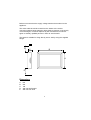
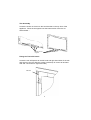
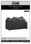
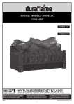
INSTALLATION AND USER INSTRUCTION GUIDE
Inspire
Model No (s)
FWR**0R*
FWR**ER*
** Denotes fuel effect type and trim colour
* Denotes trim type
0 Denotes UK model
E denotes European model
Electric Heater
This guide should be used to install and care for your
Flavel Electric heater.
Read all information carefully prior to
installation and use.
Installation
IMPORTANT
Please read the instructions below before
installation or use of this Flavel Electric Heater.
NEVER
use this heater where it may come into contact with water
i.e. bathroom, shower room, kitchen.
NEVER
leave unsupervised children where the heater is left
switched ON or is left unguarded.
NEVER
use this heater beneath a fixed socket
outlet.
NEVER
cover or obstruct the fan outlet, as this
will cause the appliance to overheat.
NEVER
install the heater close to combustible
materials i.e. curtains or similar. Allow a
minimum of one metre around the heater.
NEVER
route the mains cable beneath carpet.
NEVER
use aerosols or similar close to the heater.
NEVER
use the heater to dry clothes or similar.
NEVER
use the heater by means of an automatic
control or timer, as this may cause risk of
fire if the heater is moved or covered.
NEVER
fit the heater directly onto carpet or similar
material. It should be fitted onto a suitable
non-combustible hearth
The appliance MUST be disconnected from the mains supply before
commencing cleaning, or maintenance.
Ensure the heater is firmly secured to the fixing plain to
prevent it from falling forward.
Use a suitable fireguard to protect both the infirm and young children who
could come into contact with the heater.
DO NOT COVER
1
Appliance Data
Supply Voltage
Fuse Rating
Heating Element
230V ac, 50Hz
13 Amp
2 x 500W
Mains Cable
Illumination
1 x 1.8M PVC 1mm2
2 x 20W Low Energy Bulb
The Flavel Electric Heater is manufactured by: CFM Europe Limited
Trentham Lakes
Stoke on Trent
Staffordshire ST4 4TJ
Installation Requirements
The Flavel Electric heater is supplied with a moulded three-pin plug (13
Amp) and approximately 1.8 metres of flexible mains cable (1mm2). The
appliance and surround should therefore be located close to a suitable
mains socket to enable connection. The electrical socket MUST be easily
accessible to allow disconnection.
This heater MUST be earthed. If in any doubt consult a suitable competent
person.
Connections
L = Brown N = Blue
E = Green / Yellow
Replacement fuses should be approved and conform to BS 1362.
The rating plate is located at the bottom of the product, alongside the on /
off switch. The model number and serial number of the product will be
required when booking a service visit.
2
Before use ensure that the supply voltage matches that marked on the
appliance.
The mains cable should be routed from the heater to the socket
connection without being trapped or being liable to damage. If the supply
cord is damaged, it must be replaced by the manufacturer, its service
agent or similarly qualified persons in order to avoid hazard.
The heater is suitable for fixing directly onto a wall by using the supplied
hanger.
D
C
B
A
E
Dimensions
A
B
C
D
E
615
910
145
300 min shelf height
250 min from floor
3
Unpacking The Appliance
The Flavel Electric heater is supplied in a single pack carton. All
Instructions should be read prior to unpacking or installing the appliance.
Ensure all parts including loose items have been removed prior to
discarding the packaging.
Product Checklist
1
1
1
1
1
1
2
2
off
off
off
off
off
off
off
off
Flavel Electric Heater Main Body
Remote Control Handset with Battery
Trim Assembly (in polythene bag)
Mounting Hanger
Fixing Kit
Instruction / Guarantee Literature
Pebble Pack
Infill Panels (supplied with 4 off fixing screws)
Appliance Fixing
The heater must be fixed to a suitable wall using the mounting hanger
provided.
Heater Assembly
Laying the Pebbles
Before assembling the trim to the appliance, lay the pebbles onto the
plastic front form, to give the best decorative effect.
4
Trim Assembly
Locate the hooks on the trim to the hook bracket on the top front of the
appliance. Place the 6 magnets onto the base section of the trim as
shown below :-
Position of 6 off
magnets
Fitting the Trim Infill Panels
Locate the trim infill panels to the left hand and right hand sides of the trim
and secure to the trim with the screws provided (2 off screws to left hand
side and 2 off screws to right hand side)
Infill Panel
5
Operation Of The Heater
Fire on / flame
effect only
Fire off
Low heat on / off
High heat on / off
The heater is operated via the use of a remote control handset. A master
ON / OFF switch it situated underneath the appliance on the left hand
side. This is used to turn the appliance completely off.
Switch
Marking
Master ON /OFF
O
I
Operation
On / Off. Depress to I,
this supplies power to the
appliance and places it in a
standby mode.
All further operations are carried out by using the remote control
handset.
a)
b)
c)
d)
e)
Ensure that the appliance is plugged in and switched on.
To turn fire on press the fire on / flame effect button.
For low heat, ensure that the flame effect is on and then press the
low heat button once. To turn the low heat off, press the low heat
button a second time. The fire will now be running with flame effect
only.
For high heat, ensure that the flame effect and low heat settings have
been switched on then press the high heat button. The high heat
button will only work if the flame effect and low heat have already
been switched on. To turn high heat off, press the high heat button a
second time. The fire will now be running with low heat.
To place the fire in a standby mode at any time, press the fire off
button.
6
IMPORTANT :
Safety Cut Out
This appliance is fitted with an automatic safety cut out. This operates if
the air outlet at the top of the product becomes covered or blocked. This
will prevent the fan heater from operating.
In order to RESET the appliance the following procedure should be
followed:Switch OFF the appliance and disconnect the appliance from the mains
supply
Leave the appliance disconnected for a MINIMUM of 10mins
Check the appliance is free from all obstructions and remove safely
Switch ON the appliance at the mains supply socket
Operate the appliance as shown on the previous page
If the appliance fails to operate, repeat the above procedure ENSURING
the appliance is disconnected from the mains supply at the wall socket.
If after repeating this procedure the appliance fails to operate CHECK the
fuse within the wall socket / plug. If after carrying out both of the above
procedures the appliance still fails to operate, then call a suitably qualified
person or CFM Europe Ltd. Service Centre on the number shown on the
rear cover of this booklet.
Care and Cleaning
Always disconnect the appliance from mains supply and allow to cool
before any cleaning operation begins.
Metal painted parts may be cleaned using a clean, damp cloth.
Never use any abrasive cleaners and chemical agents as damage may
occur to the paint finish.
7
Maintenance
WARNING
BEFORE CARRYING OUT ANY MAINTENANCE, ENSURE
THAT THE APPLIANCE IS DISCONNECTED FROM THE
MAINS ELECTRICAL SUPPLY. IF IN DOUBT SEEK THE
ASSISTANCE OF A SUITABLY QUALIFIED
PERSON.
It is advisable to use genuine Flavel replacement parts
available from your supplier or direct from CFM Europe Ltd. (Contact
details on the rear of this booklet)
Bulb Replacement
Disconnect the appliance from the mains supply.
Remove the decorative trim assembly.
Remove the pebble and emberbed.
Removable
panel
Remove the removable panel by unscrewing the 4 screws.
Remove the coloured filter from the bulb and release the bulb from its
housing
Re-assemble in reverse order.
Spare Parts List
20W energy saving bulb
Pebble pack
Coloured filter
B-62450
B-81770
B-84560
8
CONTACT INFORMATION
Technical Queries
01782 339000
Service / Fault Enquires
08700 101187
The Following Information May Be Required When Contacting Flavel For
Advice :Address
Postcode
Model No.
Serial No
Fault
The products serial number and model number can be found on the rating
plate which is affixed to the bottom L/H side of the front panel, behind the
ashpan cover.
Due to our policy of continual improvement and development the exact
accuracy of descriptions and illustrations cannot be guaranteed.
Part No. B-94650
Issue 2
CFM Europe Ltd
Trentham Lakes
Stoke-on-Trent
Staffordshire
ST4 4TJ
Telephone 01782 339000
www.cfm-europe.com