1
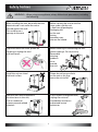
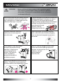
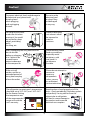
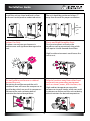
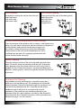
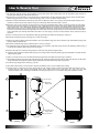
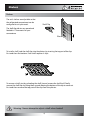
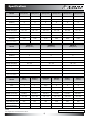
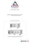
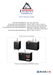
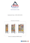
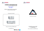
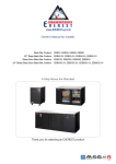
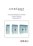
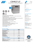
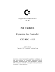
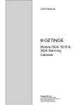
www.EVERESTref.com
Owner’s Manual for models:
Bottom Mount Reach-Ins
EBR1, EBWR1, EBWRH2, EBNR2, EBR2, EBR3
EBR1-D, EBNR2-D, EBR2-D
EBF1, EBWF1, EBWFH2, EBNF2, EBF2, EBF3
EBF1-D, EBNF2-D, EBF2-D
EBWRFH2, EBRF2, EBRF2-D, EBRF3
EBGR1, EBGNR2, EBGR2
A Step Above the Standard
Thank you for selecting an EVEREST product
R
C
LI S
T ED
US
ISO-9001
Safety Notices
REFRIGERATION
WARNING - When using your appliance, always follow basic precautions, including
the following :
When installing the unit, be careful that the
electrical cord is not under the unit or
pressed against the wall.
This could cause a
damage to the cord.
Before starting the unit for the first
time, make sure the unit
is free from all packaging.
Packaging left
on the unit
during
operation may
cause a fire hazard.
To prevent electrical shock, please do
not plug or unplug the cord
with wet hands.
Before cleaning or maintaining the unit,
please unplug it. Do not use any
flammable
cleaning
products
on or
around
the unit.
Install the unit on a hard
and level surface.
Please do not hang or climb
on the unit as this may
cause the unit to fall.
Please do not store temperature
sensitive items in the unit,
such as medical or
science research related
materials.
If you suspect a refrigerant leak,
unplug the unit and
immediately contact an
authorized service
technician.
1
Safety Notices
WARNING -
REFRIGERATION
Read and follow all safety notices in this installation guide.
These notices provide helpful safety and efficient operation
information. Failure to do so may lead to serious injury and /
or damage to the unit.
To minimize shock and fire hazards, be sure
not to overload the outlet into which the
unit is plugged into. A dedicated circuit of
sufficient amperage is required.
To prevent damage to the electrical components,
have the unit plugged in directly to its own circuit. EVEREST is not responsible for any damage caused by improper electrical connections
resulting from electrical power failure, use of
extension cords & surge
protectors, and any
voltage drops to the unit.
To prevent electrical shock and
malfunction, do not spray the
unit with water.
Clean the pronges of the electrical plug
with a soft cloth or brush before plugging
it into an electrical receptacle to prevent a
fire hazard.
Do not place or store any objects
on top of the product during
operation. It might cause
severe damage to the
product. The machine
room is located on
top and disclosed for a
ventilation purpose.
When it is time to salvage the unit, make
sure to remove the rubber gaskets from
the doors to prevent the risk of
children or animals
getting trapped
inside the unit.
Keep the unit upright at all times during
delivery. Tilting the unit during delivery
will cause harm to the refrigeration system.
2
Caution!
REFRIGERATION
To prevent electrical shock and damage to
the electrical cord, please hold
the plug head
when plugging
and unplugging
the unit.
Do not use the
electrical cord
or plug if they
are damaged
in any way.
Do not put your hands
under the unit when
moving it. You could
be injured by sharp
edges, protruding
parts,
crushing, etc.
Avoid installing the
unit where it could
be exposed to
water or
moisture.
After unplugging the unit, please wait at
least 6 minutes
6 minutes!
before re-plugging
it in. Failure to do
so could cause
extensive damage
to the compressor.
Avoid touching frozen
foods or containers,
especially metal
containers, with
wet hands. It
could cause
frostbite.
If the unit will
not be used for an
extended period of
time, please unplug
it from the outlet.
Please do not attempt to
remove or
repair any
components
unless you are
an authorized
service technician.
The refrigerator compartment’s temperature
should be set at 33°F~54°F, and -10°F~54°F
for the freezer. Setting
the temperature out
of the recommended
ranges will void the
unit’s warranty.
Keep the doors closed properly at all the
times . Check periodically if the door gaskets
seal perfectly. Losing cold air from the
cabinet due to old gaskets
will lead to severe damage to
the product and increased
electrical consumption.
3
Installation Guide
REFRIGERATION
Install the unit on a hard and level surface
or the unit could produce undesired noises.
The unit should be positioned at least 7”
away from the wall for proper ventiliation.
Back Wall
7”
Indoor Use Only
7”
Dusty and High Humidity Areas
Outdoor use may cause a decrease in
performance and significant damage to the
unit.
Dusty environments will cause the
condenser coil to prematurely clog which
will require it to be cleaned more often.
High humid environments could cause the
unit to rust.
Do not build an enclosure or cabinet
around the unit.
Select a location away from other heat
and moisture generating equipment
such as stoves, ovens, dish washers, etc.
Restricting the airflow around the unit’s
condenser area will cause the compressor to
work harder, which can result in compressor
failure and the unit not being able to
maintain the desired temperature.
High ambient temperatures cause the
compressor to work harder, which can result
in compressor failure and the unit not being
able to maintain the desired temperature.
4
Maintenance Guide
REFRIGERATION
Shelf Cleaning
Door Gasket Cleaning
Periodically remove the shelves from the unit
and clean them
with mild soap
and warm water.
To preserve the life span of the door gasket,
clean the gasket
with mild soap
and water on
a regular basis.
Do not use the following products when cleaning
Clean the exterior of the product with a stainless steel cleaner only.
Never use steel wool, strong acids, abrasive cleaners or degreasers.
Acidic products and products containing vinegar must
be stored in sealed containers to prevent acid damage
to the interior of the unit and the evaporator coil. (Rust
resulting from the lack of or improper maintenance will
not be covered under warranty.)
Interior Cleaning
Clean the interior surface of the unit with mild soap and warm
water. Do not let water accumulate inside the unit. To prevent
water damage, wipe the interior of the unit with a dry cloth as
needed. Do not use abrasive cleaners, concentrated detergents,
bleaches, cleaning waxes, solvents or polishes to clean the interior
of the unit.
Condenser Coil Cleaning
Poor condensing unit performance is caused by heavy dust
build-up on the condenser coil. The condenser coil should be
cleaned monthly. Shine a flashlight through the condenser coil
to check for dirt between the fins. Clean the outside of the
condenser with a soft brush or a vacuum with a brush
attachment. The condenser coil should be cleaned in the
direction of the fins, top to bottom, not side to side. Be careful
not to bend the fins. Detailed instructions of this procedure can
be found on page 14 in this manual.
5
How to Reverse Door
REFRIGERATION
1. The front top grill (A) must be opened before reversing the door. Grab it from either side of its bottom edge and pull it
towards you and tilt it up until it locks into place.
2. Remove the 6 screws (B) which are located in the pre-drilled holes used to mount the door hinges on the left door pillar
(when facing the unit). 3 screws are for the top hinge and 3 screws are for the bottom hinge.
3. Note the location of the door switch tab (F) and remove it. Once the door is reversed, the tab must be installed in the same
location in relation to the unit so that it can press in the door switch when the door is closed.
4. Before the door can be removed, the tension stored in the top and bottom of the doors’ self closing springs must be safely
released. To release the tension in the springs, insert a rigid object into one of the door spring shaft’s unoccupied tension
lock screw holes (C-1, D-1). Gently turn the door spring shaft until you can easily unscrew the tension lock screw (C-2, D-2).
Remove the tension lock screw. Slowly remove the rigid object which was inserted into one of the spring shaft’s unoccupied
tension lock screw holes. When the rigid object clears the hole, the door spring will release the stored tension and the door
spring shaft will spin violently. Remember that there are two springs, the top and the bottom, whose tensions must be
released.
5. Have a second person secure and hold the door (E) against the unit while the top hinge is removed.
6. Remove the top hinge (C) by removing the 3 screws securing it.
7. Remove the door by lifting it until the bottom clears the bottom hinge (D). Ensure that the top and bottom springs and
springs’ shafts do not fall out.
8. Remove the bottom hinge (D) by removing the 3 screws securing it.
9. The right top hinge becomes the left bottom hinge (C). Install the right top hinge into the left bottom position using 3
screws. Ensure that the door hinge pins are facing up.
10. Flip the door (E) over so that the hinged part is on the left side, when facing the door.
11. Install the door onto the bottom door hinge (C). The longer of the two pins pointing upward should be inserted into the
bottom spring shaft.
12. Have a second person secure and hold the door (E) against the unit while the top hinge is installed.
13. The bottom right hinge becomes the left top hinge (D). Install the left top hinge onto the door. The two pins on the door
hinge should be facing down and the longer of the two inserted into the top door spring shaft.
14. Secure the top hinge to the unit using 3 screws.
15. The door should now be secured to the unit. Ensure that the door is secured before proceeding.
16. Tension must be added to the doors’ springs for the self closing action to work. Using two rigid objects that can be
inserted into the door springs’ unoccupied door spring shaft tension lock screw holes (C-1, D-1), turn the shaft
counterclockwise, when viewing the shaft from a birds eye perspective. 2 to 3 rotations of tension should be added.
A
MANUFACTURING
MANUFACTURING
B
C-2:Lock Screw
D
C-1:Right Top
Hinge Shaft
E
C
D
B
D-1:Right Bottom
Hinge Shaft
D-2:Lock Screw
[BEFORE]
C
[AFTER]
6
Trouble Shooting
REFRIGERATION
Please check the following before requesting service.
Symptom
Condensing unit
fails to start
Cabinet does not
maintain proper
temperature
Refrigerated
compartment is too
cold
Noisy operation
Condensation on the
exterior surface
Possible Solutions
a. Ensure the electrical cord has been connected.
b. Ensure the unit is turned on.
a. Check the door gaskets for proper seal.
b. Check to see if the temp. control setting is too
high, then adjust as necessary.
c. Avoid installing the unit next to heat generating
equipment and direct sunlight.
d. Avoid storing hot contents.
e. Ensure the doors are fully closed.
a. Adjust the temperature control to a warmer
setting.
a. Check for loose parts.
b. Check for tubing rattle.
c. Check for a bent fan blade.
d. Check for damaged fan motor bearings.
e. Ensure the unit is stable.
f. Ensure the cabinet is level.
a. Condensation on the exterior surface of the
unit is perfectly normal during periods of high
humidity.
b. Check door alignment and gaskets for proper
seal.
Sound of water
dripping
a. This is the sound of the refrigerant circulating
during the compressor rest period and it is
normal.
Exterior walls are
warm
a. Heaters have been placed around the door
openings to prevent condensation buildup.
This is normal.
Condensation on the
interior
a. Condensation can occur during hot and humid
weather with frequent or prolonged door opening.
This is normal.
b. The doors might not be closed properly. Check door
alignment and gaskets for proper seal.
7
Shelves
REFRIGERATION
Shelves
The unit’s shelves are adjustable so that
the refrigerated compartment can be
configured to suit your needs.
Shelf Clip
The shelf clip pilasters are spaced and
labeled in 1” increments for your
convenience.
Pilaster
1”
To install a shelf, hook the shelf clips into the pilasters by inserting the top part of the clips
first and then the bottom. Each shelf requires 4 clips.
To remove a shelf, start by unloading the shelf. Second, remove the shelf itself. Finally,
remove the shelf clips by tilting them up and allowing the bottom of the clip to come out
first and then remove the top part of the clip from the pilaster.
Warning - Never attempt to adjust a shelf when loaded!
8
Specifications
Specification
REFRIGERATION
EBR1
EBWR1
EBWRH2
EBNR2
EBR2
EBR3
Model
(Refrigerator)
(Refrigerator)
(Refrigerator)
(Refrigerator)
(Refrigerator)
(Refrigerator)
Capacity(Cu.Ft.)
20
22
22
33
50
70
Door
1
1
2(H)
2
2
3
Shelves
3
3
3
6
6
9
Compressor (HP)
1/4
1/4
1/4
1/3
1/3 +
1/3 x 2
Power (V-Hz-Ph)
115-60-1
115-60-1
115-60-1
115-60-1
115-60-1
115-60-1
Temp. Range(F)
33 ~ 54
33 ~ 54
33 ~ 54
33 ~ 54
33 ~ 54
33 ~ 54
Refrigerant
R-134A
R-134A
R-134A
R-134A
R-134A
R-134A
Crated Weight(LBS)
305
310
317
375
463
650
Amps(A)
4.10
4.30
4.30
4.86
4.92
9.49
Ext. Dimensions
27 x 31 1/2 x 75 3/4
(W x D x H* inches)
29 1/4 x 31 1/2 x 75 3/4 29 1/4 x 31 1/2 x 75 3/4 39 1/2 x 31 1/2 x 75 3/4 54 1/4 x 31 1/2 x 75 3/4
EBR1-D
EBNR2-D
75 x 31 1/2 x 75 3/4
EBR2-D
Model
(Refrigerator)
(Refrigerator)
(Refrigerator)
Capacity(Cu.Ft.)
22
37
53
Door
1
2
2
Shelves
3
6
6
Compressor (HP)
1/4
1/3
1/3 +
Power (V-Hz-Ph)
115-60-1
115-60-1
115-60-1
Temp. Range(F)
33 ~ 54
33 ~ 54
33 ~ 54
Refrigerant
R-134A
R-134A
R-134A
Crated Weight(LBS)
315
390
474
Amps(A)
5.35
4.86
4.92
Ext. Dimensions
27 x 34 1/2 x 75 3/4
39 1/2 x 34 1/2 x 75 3/4
54 1/4 x 34 1/2 x 75 3/4
(W x D x H* inches)
Model
(Freezer)
EBF1
EBWF1
EBWFH2
(Freezer)
(Freezer)
(Freezer)
(Freezer)
Capacity(Cu.Ft.)
20
22
22
33
50
70
(Freezer)
EBNF2
EBF2
EBF3
Door
1
1
2(H)
2
2
3
Shelves
3
3
3
6
6
9
Compressor (HP)
1/2 +
1/2 +
1/2 +
3/4
3/4+
1/2 + x 2
Power (V-Hz-Ph)
115-60-1
115-60-1
115-60-1
115-60-1
115-60-1
230-60-1
Temp. Range(F)
-10 ~ 54
-10 ~ 54
-10 ~ 54
-10 ~ 54
-10 ~ 54
-10 ~ 54
Refrigerant
R-404A
R-404A
R-404A
R-404A
R-404A
R-404A
Crated Weight(LBS)
307
317
322
408
533
670
7.59
7.59
7.94
7.95
Amps(A)
Ext. Dimensions
(W x D x H* inches)
7.59
27 x 31 1/2 x 75 3/4
29 1/4 x 31 1/2 x 75 3/4 29 1/4 x 31 1/2 x 75 3/4 39 1/2 x 31 1/2 x 75 3/4 54 1/4 x 31 1/2 x 75 3/4
[NOTE]
*Ext. height does not include 5” for casters.
10.98
75 x 31 1/2 x 75 3/4
Specifications subject to change without notice.
9
Specifications
Specification
REFRIGERATION
Model
EBF1-D
EBNF2-D
EBF2-D
Capacity(Cu.Ft.)
22
37
53
Door
1
2
2
Shelves
3
6
6
Compressor (HP)
1/2+
3/4
3/4+
Power (V-Hz-Ph)
115-60-1
115-60-1
115-60-1
Temp. Range(F)
-10 ~ 54
-10 ~ 54
-10 ~ 54
Refrigerant
R-404A
R-404A
R-404A
Crated Weight(LBS)
316
320
505
Amps(A)
7.59
7.94
7.95
Ext. Dimensions
27 x 34 1/2 x 75 3/4
39 1/2 x 34 1/2 x 75 3/4
54 1/4 x 34 1/2 x 75 3/4
(W x D x H* inches)
(Freezer)
(Freezer)
EBRF2
(Freezer)
Model
EBWRFH2
(Daul Temp)
(Daul Temp)
(Daul Temp)
EBRF2-D
(Daul Temp)
EBRF3
Capacity(Cu.Ft.)
9.64(Ref), 9.04(Frz)
20(Ref), 20(Frz)
22(Ref), 22(Frz)
38(Ref), 19(Frz)
Door
2(H)
2
2
3
Shelves
2
6
6
9
Compressor (HP)
1/2 +
1/4(Ref), 1/2+(Frz)
1/4(Ref), 1/2+(Frz)
1/3+(Ref), 1/2+(Frz)
Power (V-Hz-Ph)
115-60-1
115-60-1
115-60-1
115-60-1
Temp. Range(F)
33 ~ 54
-10 ~ 54
33 ~ 54
-10 ~ 54
Refrigerant
R-404A
R-134A(Ref), R-404A(Frz)
R-134A(Ref), R-404A(Frz)
R-134A(Ref), R-404A(Frz)
Crated Weight(LBS)
341
546
573
631
Amps(A)
7.59
10.87
10.87
14.06
Ext. Dimensions
29 1/4 x 31 1/2 x 75 3/4
54 1/4 x 31 1/2 x 75 3/4
54 1/4 x 34 1/2 x 75 3/4
75 x 31 1/2 x 75 3/4
(W x D x H* inches)
EBGR1
EBGNR2
EBGR2
Model
(Refrigerator)
(Refrigerator)
(Refrigerator)
Capacity(Cu.Ft.)
18
28
40
Door
1
2
2
Shelves
4
8
8
Compressor (HP)
1/3
1/3 +
1/2+
Power (V-Hz-Ph)
115-60-1
115-60-1
115-60-1
Temp. Range(F)
33 ~ 54
33 ~ 54
33 ~ 54
Refrigerant
R-134A
R-134A
R-134A
Crated Weight(LBS)
330
421
518
Amps(A)
5.35
8.02
8.02
Ext. Dimensions
27 x 31 1/2 x 75 3/4
39 1/2 x 31 1/2 x 75 3/4
54 1/2 x 31 1/2 x 75 3/4
(W x D†x H* inches)
[NOTE] H : Half Door
* Ext. height does not include 5” for casters.
† Ext. depth dimension does not include 1-1/2” for door handles.
Specifications subject to change without notice.
10
Temperature Setting
REFRIGERATION
C
A
B
D
E
* LED Display
A
B
Operation of compressor
Current cabinet temperature
* Control Buttons
C
Power button
D
Temperature setting button
E
Defrost button
* How to set desired temperature
Step 1
Press and hold “ D ” button until the LED displays “ set ” symbol and a number
consecutively. The number is the previous setting temperature (Recommended
setting - Refrigerator : 35℉, Freezer : -4℉). When the number is flashing,
release the button.
Caution: If “ PS ” symbol appears on the LED, it means that you pressed and held
“ D ” button too long. Release it, and then press “ D ” button twice to restart the
temperature setting.
Step 2
While flashing the number, set your desired temperature by pressing “ C ” (high) or
“ E ” (low) button. The number increases or decreases by a decimal point.
Note: Your new setting temperature should be in the range of between 33℉ and
54 °F for refrigerator, and -10℉ and 54℉ for freezer.
Step 3
Press “ D ” button to get out of the setting mode. The LED will show the current
cabinet temperature.
11
Product Drawings
REFRIGERATION
29 1/4"
27"
28 1/4"
28 1/4"
80 3/4"
75 3/4"
80 3/4"
75 3/4"
80 3/4"
75 3/4"
5"
5"
5"
EBR1 / EBF1
EBWR1 / EBWF1
39 1/2"
EBWRH2 / EBWFH2
54 1/4"
75"
31 1/2"
31 1/2"
54 1/4"
56 3/4"
49 1/2"
31 1/2"
24"
19 1/4"
58 1/2"
31 1/2"
56 3/4"
31 1/2"
56 3/4"
31 1/2"
26 1/2"
29 1/4"
26 1/2"
19 1/4"
80 3/4"
75 3/4"
5"
5"
5"
EBR2 / EBF2
EBR3 / EBR3
39 1/2"
27"
54 1/4"
59 3/4"
26 1/2"
19 1/4"
26 1/2"
80 3/4"
75 3/4"
80 3/4"
75 3/4"
80 3/4"
75 3/4"
5"
5"
5"
EBR1-D / EBF1-D
Deep Series
34 1/2"
52 1/2"
34 1/2"
59 3/4"
34 1/2"
19 1/4"
26 1/2"
24"
80 3/4"
75 3/4"
80 3/4"
75 3/4"
EBNR2 / EBNF2
24"
26 1/2"
EBNR2-D / EBNF2-D
Deep Series
12
EBR2-D / EBF2-D
Deep Series
3 3/8"
5"
12 1/2" 5"
12 1/2" 5"
2 3/8"
2 3/8"
80 3/4"
75 3/4"
F
R
F
80 3/4"
75 3/4"
R
80 3/4"
75 3/4"
26 1/2"
54 1/4"
31 1/2"
56 3/4"
59 3/4"
34 1/2"
31 1/2"
5"
5"
5"
56 3/4"
31 1/2"
49 1/2"
31 1/2"
56 3/4"
31 1/2"
80 3/4"
75 3/4"
80 3/4"
75 3/4"
80 3/4"
75 3/4"
5"
5"
5"
13
F
24"
R
R
26 1/2"
58 1/2"
31 1/2"
R
24"
26 1/2"
80 3/4"
75 3/4"
80 3/4"
63 1/4"
80 3/4"
63 1/4"
F
EBGR2
EBGNR2
EBGR1
3 3/8"
28 1/4"
24"
26 1/2"
26 1/2"
26 1/2"
19 1/4"
19 1/4"
26 1/2"
54 1/4"
39 1/2"
27"
75"
54 1/4"
54 1/4"
EBRF3
EBRF2-D
(Deep series)
EBRF2
EBWRFH2
Deep series
29 1/4"
34 1/2"
31 1/2"
REFRIGERATION
Product Drawings
Critical Information
REFRIGERATION
CONDENSER COIL MAINTENANCE
Failure to maintain a clean condenser coil will eventually result in compressor failure and product loss.
Mechanical failures due to a lack of or improper maintenance are not covered under warranty.
Keeping the condenser coil clean will maximize energy savings.
Cleaning of the condenser coil is part of regular maintenance and is not covered under warranty.
CONDENSER COIL CLEANING PROCEDURE
Please use the following steps to clean the condenser coil. If you have any questions regarding this
procedure, please call the Everest customer service department at (800) 444-6285.
1. Unplug the unit from the wall.
2. Remove the front bottom grill. It is attached with Philips head screws.
3. Clean the condenser coil using a vacuum or brush. The fins of the condenser coil should only be
cleaned and swept in the direction of the fins, which is up and down. Be careful not to bend the fins.
4. In some instances, the condenser coil may require professional cleaning due to a buildup of grease
and dust. In this case, contact a local refrigeration company to take care of this for you.
5. Ensure no tools or parts have been left in the condensing unit area.
6. Replace the front bottom grill.
The warranty card below must be submitted to Everest within thirty (30) days of purchase.
WARRANTY REGISTRATION CARD
Business Name :
Telephone : (
)
Address :
City :
State :
Place of Purchase :
Zip :
Date Purchased :
Model No :
Date Installed :
Cabinet Serial No :
3 YEAR PARTS and LABOR WARRANTY
(Applicable to units purchased after July 1, 2014.)
5 YEAR COMPRESSOR WARRANTY
Name of Business Owner :
Date :
Signature of Business Owner :
14
Warranty Certificate
REFRIGERATION
EVEREST warrants to the original purchaser of every new EVEREST unit, the cabinet and all parts thereof, to be free from defects in
material or workmanship, under normal and proper use and maintenance service as specified by EVEREST and upon proper
installation and start-up in accordance with the instruction packet supplied with each unit. Our obligation under this warranty is
limited to a period of three (3) years from the date of original installation or thirty six (36) months after shipment date from EVEREST,
which ever occurs first. This is applicable to units purchased after July 1, 2014. Any part covered under this warranty that is determined
by EVEREST to have been defective within three (3) years of original installation or thirty six (36) months after shipment date from the
manufacturer, which ever occurs first, is limited to the repair or replacement, including labor charges, of defective parts or assemblies.
The labor warranty shall include standard straight time labor charges only and reasonable travel time, as determined by EVEREST.
All warranty claims for labor or parts must be made directly through EVEREST. All claims shall include: unit model number, cabinet
serial number, proof of new product purchase, installation date, and all pertinent information related to the alleged defect. For
compressor warranty claims, the compressor tag shall be returned to EVEREST with the above listed information.
EVEREST's sole obligation under this warranty is limited to either the repair or replacement of parts, subject to the additional limitations
below. This warranty neither assumes nor authorizes any person to assume obligations other than those expressly covered by this
warranty.
A. NON WARRANTY PARTS
EVEREST excludes specific parts exposed to normal wear and tear. These parts include, but are not limited to, lamps,
gaskets, casters, shelves and shelf clips, pans, bin and pan dividers and airflow guards.
B. INDIRECT OR CONSEQUENTIAL DAMAGE
EVEREST does not warrant economic loss, profit loss, or special, indirect or consequential damages including without
limitation, losses or damages arising from food or product spoilage claims caused by refrigeration failure.
C. IMPROPER USAGE
EVEREST is not responsible for parts or labor coverage for component failure and or other damages resulting from
improper usage, installation or failure to clean and/or maintain product as set forth in the user's manual provided with this
unit. All EVEREST products are designed for commercial usage, not for residential use. Therefore, the warranty will not be
honored if product is installed in a residential house.
D. WARRANTY IS NOT TRANSFERABLE
Warranty is limited to only the original purchaser/user to whom delivered. It is not transferable.
E. ALTERATION, NEGLECT, MISUSE, ABUSE, ACCIDENT, DAMAGE DURING TRANSIT OR INSTALLATION, FIRE, FLOOD, ACTS
OF GOD.
EVEREST is not responsible for malfunctions due to alteration, neglect, misuse, abuse, accident, damage during transit or
installation, fire, flood, storm, and/or other acts of God. And EVEREST is not responsible for any improper electrical
connections resulting from electrical power failure, the use of extension cords, and low voltage or voltage drops to the unit.
F. UNAUTHORIZED MODIFICATION
EVEREST is not responsible for the repair or replacement of failed or damaged components resulting from unauthorized
modifications to units or the use of non-standard parts without prior written approval from EVEREST.
G. RESIDENTIAL, NON-COMMERCIAL USE
This warranty does not apply to a unit installed in a residential setting. This unit is for commercial use only.
H. OUTSIDE THE U.S.
This warranty does not apply to any parts and/or labor warranty claims made on units sold or used outside of the United
States.
ADDITIONAL TWO(2) YEAR COMPRESSOR WARRANTY
In addition to the warranty set forth above, EVEREST warrants the hermetically sealed compressor for an additional two (2) years, not
to exceed sixty (60) months from the date of shipment from EVEREST, provided upon receipt of the compressor, manufacturer
examination shows the sealed compressor to be defective. This compressor warranty does not apply to shipping or labor costs or
any other parts of the unit whether electrical or mechanical.
These warranties are exclusive and in lieu of all other warranties, expressed or implied, and all other obligations or liabilities on our
part, and we neither assume nor authorize any other person to assume for us any other obligation or liability in connection with
the sale of said refrigeration units or any part thereof.
15
Memo
REFRIGERATION
REFRIGERATION
Memo
REFRIGERATION
REFRIGERATION
Memo
REFRIGERATION
REFRIGERATION
REFRIGERATION
REFRIGERATION
A Step Above the Standard
201 W. Artesia Blvd., Compton CA 90220
Tel : 310-323-6586, 800-444-6285
Fax : 310-323-7524, 310-761-1127
Visit our website at www.EVERESTref.com