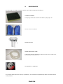
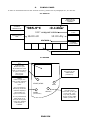
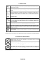
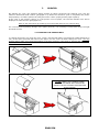
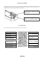
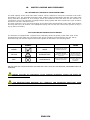
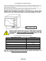
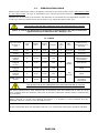
1
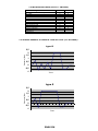
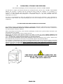
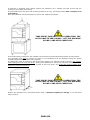
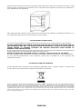
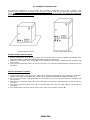
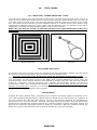
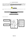
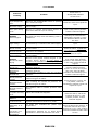
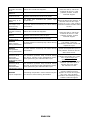
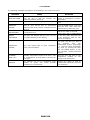
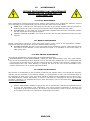
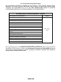
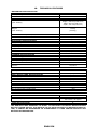
0051 B60 - Rev.1.11 - 2014.06.04 1. CONTENTS 1. CONTENTS 1.1 INTENDED USE 1.2 GENERAL WARNINGS 1.3 INFORMATION TABLE (Annex D - EN13060) 1.4 GRAPHIC EXAMPLE OF VARIOUS TYPES OF CYCLE (ref. EN 13060)* 2. SAFETY 2.1 SAFETY SIMBOLS 2.2 SAFETY DEVICES 2.3.OPERATOR TRAINING 2.4. SAFETY PROCEDURES FOR POTENTIALLY DANGEROUS OPERATIONS 3. PACKAGING, STORAGE AND DISPOSAL 3.1 UNPACKING AND POSITIONING THE AUTOCLAVE 3.2 ELECTRICAL CONNECTIONS 3.3 DISPOSAL AND/OR SCRAPING 4. GENERAL INSTALLATION RULES 4.1 HYDRAULIC CONNECTIONS 5. ACCESSORIES 6. CONROL PANEL 6.1 DISPLAY 6.2 KEYPAD 6.3 SERVICE ICONS 6.4 CONDUCTIVITY METER SYMBOLS 7. PRINTER 7.1 CHANGING THE PRINTER ROLL 7.2 PRINT HEAD CLEANING 7.3. PRINTING SLIP 8. USER MENU 8.1 ENGLISH 8.2 TIME (hh:mm:ss) 8.3 DATE (dd:mm:yy) 8.4 CYCLES RE-PRINT 8.5 “ECON ON/OFF” FUNCTION 9. FIRST TIME START-UP 9.1 CLOSING THE DOOR 9.2 OPENING THE DOOR 9.3 TEST CYCLE 10. WATER LOADING AND DISCHARGE 10.1 AUTOMATIC LOADING OF CLEAN WATER TANK 10.2 CLEAN WATER CONDUCTIVITY READER 10.3 DRAINING THE CLEAN WATER TANK 10.4 WATER QUALITY TABLE (UNI EN 13060) 11. STERILISATION TABLE 11.1 TABLE 11.2 EXTRA DRY 11.3 NIGHT CYCLE 12. TEST CYCLES 12.1 “HELIX TEST – BOWIE & DICK TEST” CYCLE 12.2 VACUUM TEST CYCLE 12.3 BIOASSAY 13. STERILISATION RECOMMENDATIONS 14. ALARMS AND ERRORS 14.1 ALARMS 14.2 ERRORS 15. MAINTENANCE 15.1 DAILY MAINTENANCE 15.2 WEEKLY MAINTENANCE 15.3 SEMI-ANNUAL MAINTENANCE 15.4 YEARLY MAINTENANCE 15.5 SCHEDULED MAINTENANCE TABLE 16. TECHNICAL FEATURES 17. WARRANTY ENGLISH 1.1 INTENDED USE Dear Customer, The autoclave is a device designed for water steam sterilization of small sized tools and professional equipment, and is widely used for medical purposes by general practitioners and dentists, in salons that deal with personal hygiene and body care and also in veterinary surgeries. It is also used for sterilizing materials and equipment that come into contact with blood or physiological liquids, such as instruments used by beauticians, tattoo artists, piercers and hairdressers. The very specific sterilization loads used in these sectors of applications require different performance features for the sterilization cycles. It is, therefore, advisable that this device is used by professional personnel duly trained. It is of fundamental importance for the sterilizer and the respective equipment to be used solely for the type of product for which they were designed. We therefore request you to consult the Declaration of Conformity of this appliance: the Class to which the appliance belongs is indicated in the “Category” box. The“ Sterilization Table” (Chap. 11) gives all the information necessary for establishing the type of cycle to be used for sterilizing the various instruments. 1.2 GENERAL WARNINGS We recommend that you read the Instruction Manual carefully before beginning to use the device, to ensure that the operations required are carried out correctly: DO NOT carry out operations other than those described in this booklet. The Manufacturer declines all responsibility for direct or indirect damage to objects, persons or animals deriving from improper use of the appliance. The machine must be used by responsible adults only. Position the machine in a place where it is not accessible to children. Install the machine in a position where it is easy to reach the plug. Do not use the machine near inflammable or explosive sources. Use the machine in dry protected areas. Check the condition of the power cable periodically: do not use the appliance if the power cable is not perfectly intact. Do not carry out maintenance with the machine running or if it is plugged into the power socket. Do not approach the machine with inflammable material. Always use personal protection devices, in compliance with the applicable directives. Do not use the appliance for purposes other than those mentioned in this Instruction Manual. Read the paragraph concerning the technical features carefully before starting up the appliance. For your safety, make sure you pay great attention to the instructions given below. Warning, the autoclave chamber may be hot with the presence of steam or boiling liquids. Possible burn hazard. PERSONS UNDER THE INFLUENCE OF MEDICINES, DRUGS OR ALCOHOL ARE STRICTLY PROHIBITED FROM USING THE AUTOCLAVE. ENGLISH 1.3 INFORMATION TABLE (Annex D - EN13060) REQUIREMENTS Dynamic steriliser chamber pressure Air outlet Empty chamber Solid load Small porous objects Small sized porous loads Full porous load Type B hollow load Type A hollow load Multiple casing Drying, solid load Drying, porous load Residual air X = present B S X X X X X X X X X X X X X X X X X X 1.4 GRAPHIC EXAMPLE OF VARIOUS TYPES OF CYCLE (ref. EN 13060)* type B 2,5 Pressure (Bar) 2 1,5 1 0,5 0 -0,5 -1 Time type S 2,5 Pressure (Bar) 2 1,5 1 0,5 0 -0,5 -1 Time ENGLISH 2. SAFETY 2.1 SAFETY SIMBOLS ATTENTION: READ CAREFULLY THE INSTRUCTIONS OF THE USER’S MANUAL WARNING: DANGER OF HAND CRUSHING VOLTAGE ATTENTION HIGH TEMPERATURE EARTH CONNECTION For the meaning of the control panel symbols, see chap. 6 2.2 SAFETY DEVICES The safety devices envisaged are as follows: 1. Six door control micro-switches and automatic coupling system are independent of one another and ensure the door system is closed and locked correctly. In the event of a problem, an alarm alerts the user that the cycle cannot start. If the cycle is already running and a problem is detected, the microprocessor interrupts the process and immediately discharges the machine pressure. 2. Three different mechanical temperature thermostats ensure that the temperature of the various components does not accidentally exceed the maximum allowable temperature. Of the three thermostats described, two must be manually reset which the other is automatically reset 3. Two electronic temperature sensors continuously monitor all critical points of the machine, preventing overheating errors during the work process. 4. A mechanical safety valve against overpressure eliminates the risk of explosion. 5. An electronic pressure transducer monitors all the solenoid valves and opens them in case of overpressure. 6. Two type gG 16A 500V~ fuses, size 10x38mm positioned inside the autoclave. 7. Tests have been carried out on the container under pressure, which is an integral part of the machine, in accordance with that required by directive 97-23-EC (PED). ENGLISH 2.3.OPERATOR TRAINING The operators in charge of using the autoclave must be properly educated and trained. In particular, the RESPONSIBLE AUTHORITY (that is, the individual or group responsible for the use and maintenance of the machine) must ensure that all personnel who use the autoclave have been trained to use it correctly and safely. The responsible authority must also ensure ongoing training for all operator personnel through training courses. Operator attendance at must courses must be recorded and these attendance reports must be archived. The operators must demonstrate a correct understanding of the information presented during the training courses. 2.4. SAFETY PROCEDURES FOR POTENTIALLY DANGEROUS OPERATIONS The operator must use proper personal protection equipment to remove materials from the sterilisation chamber (such as thermally-insulated gloves provided by the manufacturer). The materials inside the sterilisation chamber must always be considered dangerous since they can reach high temperatures and any time and may become possible sources of burn hazards. The sterilisation chamber and the door can reach very high temperatures and; therefore, may represent potential burn hazards. Steam or hot liquids may be present inside the sterilisation chamber. THE RESPONSIBLE AUTHORITY must properly educate operators so they wear suitable personal protection equipment when using the autoclave and especially when removing sterilised materials from the sterilisation chamber. ENGLISH 3. PACKAGING, STORAGE AND DISPOSAL The cardboard packaging used for transporting the autoclave IS NOT STERILE. The autoclave is fragile and should therefore be transported with extreme care. DO NOT TURN UPSIDE DOWN. The sterilizer is packed with all accessories placed inside the chamber. It is wrapped in a protective polyethylene bag and then placed inside a cardboard box. To protect it against accidental impact, it is also padded with polystyrene or cardboard. Keep in a dry and protected area at a temperature of 5-30°C. The user is recommended to retain the packaging for the period of the warranty: if the equipment is returned for repair without the original packaging, the user will be charged for a new packaging at time of reshipment. 3.1 UNPACKING AND POSITIONING THE AUTOCLAVE The machine must be unpacked and installed by specialised personnel, authorised by the manufacturer. Refer to the installation manual for further information. Carefully read the instructions contained in the manual before using the machine. Before unpacking the autoclave, ensure that the packaging is intact and in good condition and that it has not been broken or crushed. If autoclave is equipped with a stand, unpack this first. Remove the box and the filler material. Position the stand on a flat, dry surface with a capacity of at least 250 kg. Carefully check that the wheels on the stand have not suffered any damage and are free to move. At this point, engage both the brakes on the front wheels. Once you have checked that it has not been damaged, remove the autoclave from its box. Remove the filler material that protects the autoclave from accidental impacts during transportation. The autoclave is equipped with four slots for eyebolts positioned on top of it in the four corners. Screw the four eyebolts into their slots along the entire length of the thread. Use the straps supplied to lift the autoclave by means of appropriate lifting systems that comply with applicable legislation and that have a capacity of at least 250 kg, Always use all four eyebolts supplied with the machine and make sure that the eyebolts are screwed in along the entire length of the thread. TAKE GREAT CARE WITH THIS OPERATION. THE AUTOCLAVE IS VERY HEAVY. LIFT THE MACHINE SLOWLY AND VERY CAREFULLY. ENGLISH If autoclave is equipped with a stand, position the autoclave on it, making sure that all four feet are resting on the surface of the stand. If the autoclave does not come with a stand, position it on a dry, horizontal surface with a capacity of at least 250 kg. Once the autoclave has been positioned, remove the straps and eyebolts. TAKE GREAT CARE WITH THIS OPERATION. THE AUTOCLAVE IS VERY HEAVY. LIFT THE MACHINE SLOWLY AND VERY CAREFULLY. If automatic lifting systems are not available, the autoclave must be lifted using special movement bars. This operation must only be carried out when it is not possible to lift the autoclave using the special eyebolts supplied and automatic lifting systems. The lifting bars must be inserted in the special lower guides. The autoclave must be lifted by four people, each holding one side of the bar firmly, paying close attention to ensure the autoclave remains balanced. The weight of the autoclave is, in fact, greater at the front (door) and great care must be taken when lifting it to prevent overturning. TAKE GREAT CARE WITH THIS OPERATION. THE AUTOCLAVE IS VERY HEAVY. LIFT THE MACHINE SLOWLY AND VERY CAREFULLY. Position the autoclave on a horizontal surface with a minimum capacity of 250 kg, or on the stand where present. ENGLISH Always leave at least 5 cm of space on all sides of the autoclave to allow air to circulate. Also bear in mind that the water and electricity connections are on the back of the autoclave and must be accessible for easy maintenance and inspection. After positioning the autoclave, use a spirit level to check that the chamber is perfectly horizontal. If it is not, adjust the support feet until achieving the correct position. 3.2 ELECTRICAL CONNECTIONS For correct, safe operation, the autoclave must be connected to a 16 A socket with the cable supplied. DO NOT TAMPER WITH OR CHANGE THE CABLE SUPPLIED OR ANY OTHER ELECTRICAL PART OF THE MACHINE IN ANY WAY. THE MANUFACTURER DISCLAIMS ALL LIABILITY FOR DAMAGE OR INJURY CAUSED TO PERSONS, PROPERTY OR ANIMALS RESULTING FROM FAILURE TO OBSERVE THESE INSTRUCTIONS. No other electrical instrument must be connected to the same socket as the autoclave as the absorption of the machine may, in some cases, be close to the value of 16 A. NEVER USE ADAPTERS OR POWER STRIPS TO CONNECT THE AUTOCLAVE TO THE MAINS. The cable connecting the autoclave to the mains must remain accessible and easy to inspect if necessary. For the electrical characteristics of the autoclave, please refer to chapter 16 of the operating and maintenance manual. 3.3 DISPOSAL AND/OR SCRAPING For the disposal and/or scraping of any component (packaging, water, complete machine…) strictly refer to the norms in force in the country where the operation is carried out. Directive 2002/96/EC (Waste Electrical and Electronic Equipment - WEEE): information for users. This product complies with EU Directive 2002/96/ EC. The crossed-out wastebasket symbol on the appliance means that at the end of its useful lifespan, the product must be disposed of separately from ordinary household wastes. The user is responsible for delivering the appliance to an appropriate collection facility at the end of its useful lifespan. Appropriate separate collection to permit recycling, treatment and environmentally compatible disposal helps prevent negative impact on the environment and human health and promotes recycling of the materials making up the product. For more information on available collection facilities, contact your local waste collection service or the shop where you bought this appliance. ENGLISH 4. GENERAL INSTALLATION RULES The correct installation of the autoclave is essential for its proper operation. This operation must be carried out by specialised personnel, authorised by the manufacturer. Below are some general considerations regarding the installation of the autoclave. 1. The machine must be installed inside a laboratory that can only be accessed by authorised personnel. 2. The work environment must be sufficiently lit and ventilated. 3. The machine may be supplied with or without the bottom cabinet. In any case, the machine must be positioned on a flat and horizontal surface, WITH A MINIMUM LOAD CAPACITY OF 250KG. If the lower cabinet is present the wheel brakes MUST ALWAYS BE LOCKED after installation. 4. The machine must be connected to a socket with a minimum capacity of 16A. DO NOT USE ANY TYPE OF ADAPTER AND DO NOT MODIFY THE ELECTRICAL CABLE SUPPLIED WITH THE AUTOCLAVE IN ANY WAY. DO NOT CONNECT ANY OTHER MACHINE TO THE SOCKET USED TO POWER THE AUTOCLAVE. THE MANUFACTURER DECLINES ALL LIABILTY FOR ANY DAMAGE TO PERSONS, PROPERTY OR ANIMALS RESULTING FROM FAILURE TO FOLLOW THESE INSTRUCTIONS. 5. 6. 7. 8. Place the autoclave so that the sterilisation chamber is easily accessible. Do not install the autoclave next to sinks or taps as the cover of the machine is not waterproof. Do not install the machine next to heat sources (other autoclaves, ovens etc.). To prevent damage to persons, property or animals the machine must be positioned to allow run-off from the safety valve, located on the rear panel, into a safe place 9. Leave at least 15cm on each side of the autoclave to allow for proper air circulation. DURING THESE OPERATIONS AND ANY OPERATION THAT DIFFERS FROM NORMAL AUTOCLAVE USE, INCLUDING MOVEMENT, ALWAYS DISCONNECT THE MACHINE’S ELECTRICITY SUPPLY. ENGLISH 4.1 HYDRAULIC CONNECTIONS The hydraulic connections of the machine are of primary importance to its proper operation. The autoclave must always be connected to the hydraulic system, both for powering and discharge of the water. The minimum pressure of the water network must be at least 2 bar while the maximum pressure should not exceed 5 bar. Version without cabinet Version with bottom cabinet Version without bottom cabinet: 1. Connect clean water inlet “A” to the outlet of the osmosis system supplied. NEVER USE WATER THAT DOES NOT COMPLY WITH THE SPECIFICATIONS LISTED IN TABLE 10.6 2. Connect the discharge water outlet “B” to the discharge grid using the dedicated tube supplied with the autoclave. 3. Connect the condensate outlet “C” to the discharge grid using the dedicated tube supplied with the autoclave. Version with bottom cabinet: 1. Connect clean water inlet “A” to the outlet “F”(to which the supplied osmosis system is connected). NEVER USE WATER THAT DOES NOT COMPLY WITH THE SPECIFICATIONS LISTED IN TABLE 10.6 2. Connect the discharge water outlet “B” to the discharge grid using the dedicated tube supplied with the autoclave. 3. Connect the condensate outlet “C” to the discharge grid using the dedicated tube supplied with the autoclave. 4. Connect the osmosis system drain “E” to the discharge grid using the tube supplied along with the autoclave. 5. Connect the water networks power supply to the inlet of the osmosis system “D”. ENGLISH 5. ACCESSORIES The tray holder is supplied together with 4 trays and the following accessories CLEANING SPONGE The sponge should be used as indicated in paragraph 15. Gloves silicone insulation Osmotic System WATER DISCHARGE TUBE Tube to be used for discharging water from the clean water tank, as described in section 10.5. CD Software for USB Data The pictures shown above are purely explanatory. The accessories supplied may differ from those shown in the pictures. ENGLISH 6. CONROL PANEL In order to understand and use the controls correctly, please refer to paragraphs 6.1, 6.2 and 6.3. 6.1 DISPLAY PRESSURE IN STERILISATION CHAMBER STERILISATION CHAMBER TEMPERATURE 085.9°C -0.12bar SELECTED CYCLE 121° wrapped cables STERILISATION TIME 16:00 str 10:00 dry DRYING TIME VACUUM 1 CURRENT CYCLE PHASE INDICATOR ICONS (paragraph 6.3) 6.2 KEYPAD Display (section 6.1) START/STOP Starts the cycle. If pressed for more than 1 second when a cycle is running, the cycle is interrupted. DOOR Used to open the door of the machine at the end of a cycle. If it is pressed in stand-by mode the machine displays the number of cycles carried out. TECH Key used in the USER MENU (section 8). START/STOP DOOR TECH SELECT (EXTRA DRY) If it is pressed and held down for 5 seconds during the cycle, the “EXTRA DRY”option is enabled. ENGLISH SELECT Use this key to select the cycle type to be used. This key also provides access to the USER MENU (section 8) 6.3 SERVICE ICONS This icon is displayed as soon as the cycle has started and indicates that the machine door is locked. This icon indicates that a cycle is running: you will see the arrows spinning around. The icon signals there is no paper in the printer, or that the door of the printer is not properly closed. However, the machine can run cycles without causing any damage. * B The letter that appears (B or S) indicates the type of cycle selected (see the information table). USB icon: the autoclave is equipped with a software which is able to communicate and write on a USB pen drive. When the USB pen drive is inserted into its connector, the icon appears on the display. DATA SAVING ONLY BEGINS IF THE PEN DRIVE HAS BEEN INSERTED INTO ITS CONNECTOR BEFORE THE CYCLE IS STARTED. The clean water tank is full. It is therefore possible to start a new cycle. If this cycle is present no cycle can be started and you must wait for the dirty water to be emptied from the tank Allow the water to drain completely before starting a new cycle. Cycle S selected. Carefully read the manual to check type of instruments that can be sterilised. * Always observe current laws in force regarding the storage of information concerning sterilisation. 6.4 CONDUCTIVITY METER SYMBOLS GREEN indicator light: the water delivered by the osmosis system is of good quality. No action is required. YELLOW indicator light: the water delivered by the osmosis system is of degraded quality. Consult paragraph 10.2 RED indicator light: the water provided by the osmosis system is not suitable for autoclave operation. Consult paragraph 10.2 and immediately take corrective action. See also section 10.2 ENGLISH 7. PRINTER On starting any cycle, the autoclave starts printing all values concerning the selected cycle, plus the machine model and serial number (paragraph 7.3). When the autoclave cycle is completed, the printer stops printing: cut off the printout by using the built-in cutter (simply pull the paper upward). If the cover is not properly closed, or if the printer is out of paper, the relevant indicator icon will be displayed to warn the user (paragraph 6.3). Refer to the instructions provided by the local health authority for printout-filing. For a correct and long-lasting storage of the paper printouts, it is necessary to keep them away from light and heat sources. 7.1 CHANGING THE PRINTER ROLL To change the printer roll: open the cover, insert a new thermal paper roll (maximum width should be 57 mm) in the space provided and lead out the paper over the cover roll while closing the cover. Use only thermal paper. Make sure the thermal paper is correctly oriented: if the paper is inserted the wrong way up, the printouts will be blank. DO NOT INSERT THE THERMAL PAPER BETWEEN THE DOOR AND THE ROLLER. LEAVE IT ON THE OUTSIDE AS INDICATED IN THE FIGURE. ENGLISH 7.2 PRINT HEAD CLEANING If printouts are difficult to read, the print head should be cleaned using a moistened soaked in alcohol: open the printer cover, remove the paper roll and clean the head (see points shown in the picture). Use compressed air to clear dust from the interior of the printer. The print head is below the cutter. Cleaning should be carried out with the machine OFF. If the cover is not properly closed, or if printer is out of paper, the relevant indicator icon will flash on the display. 7.3. PRINTING SLIP How to read and interpret the information provided in the printouts. Model. Software release. Serial number. Cycle start date. Selected cycle. Incremental number of cycles started. Column showing time: hour, minutes, seconds. Info on the cycle underway: minimum cycle temperature and pressure values. Column showing temperature values in degrees centigrade (°C). Pressure column. Current cycle phase. Operator's signature. Cycle result. ENGLISH 8. USER MENU To access the user menu, proceed as described below: Switch-OFF the autoclave. Keep SELECT pressed and switch-ON the autoclave: release the SELECT button only when the preset language (e.g.: ENGLISH) appears on the display. Within the user menu, the pushbuttons are used in the following manner: START = proceed to the next page. DOOR and TECH = allow modifying the settings within the pages. SELECT = when pressed until the confirmation sound is given, it saves the pre-selected value (not all the pages need to save the pre-selected value). 8.1 ENGLISH use DOOR and PUMP buttons to select the required language. Press the START/STOP button to move on to... 8.2 TIME (hh:mm:ss) This page allows you to set the time. Press the DOOR button to increase the value and the PUMP button to decrease it; use the SELECT button to move the cursor to the value to be changed. Press the START/STOP button to move on to... 8.3 DATE (dd:mm:yy) This page allows you to set the date. Press the DOOR button to increase the value and the PUMP button to decrease it; use the SELECT button to move the cursor to the value to be changed. Press the START/STOP button to move on to... 8.4 CYCLES RE-PRINT This function allows you to save the last cycles executed by the machine with a single action. These cycles can be either printed from the internal or external printer by holding down the SELECT button for 5 sec. Press the START/STOP button to move on to... 8.5 “ECON ON/OFF” FUNCTION Normal autoclave operation envisages the pre-heating of the chamber when the machine is on; cycle selected but not yet running. This function allows reducing the cycle time when the machine is cold, heating the autoclave chamber before a sterilisation cycle is carried out. The pre-heating function can be disabled to allow for energy savings. The factory setting is “ECON OFF”, that is, pre-heating activated. Select “ECON ON” to disable the pre-heating function and the machine will not heat up the sterilisation chamber before beginning the sterilisation cycle. It is possible to exit the "USER MENU" mode at any time by pressing and holding down the START/STOP button. ENGLISH 9. FIRST TIME START-UP USING THE SYSTEM FOR THE FIRST TIME After the installation of the autoclave by a specialised technician (see sections 4, 4.1 and the installation manual) check the tightness of all water connections. Then proceed observing the following: 1. 2. 3. Turn on the machine using the main switch and slowly open all the water connections. Wait for the clean water tank to fill up. The time of the this operation depends on the water inlet pressure and may last up to 30 minutes. Insert at least the tray holder and observe the following points. 9.1 CLOSING THE DOOR When the machine turns on the manufacturer's logo, the autoclave model and the software version uses are shown on the display. To close the door, place it up against the boiler of the machine, lift up the handle and then release it keeping the door juxtaposed. The correct closure of the handle is signalled by a sound which,is followed by the automatic closure of the door after several seconds. The dedicated symbol appears on the display (see 6.3). WARNING, DANGER OF CRUSHING. ALWAYS PAY THE UTMOST ATTENTION WHILE THE DOOR IS CLOSING TO PREVENT YOUR FINGERS FROM BEING CRUSHED. Per To start the cycle press the START button once the door is completely closed. 9.2 OPENING THE DOOR Open the door, press the DOOR button. To ensure maximum operator safety, the autoclave proceeds to discharge any internal pressure via the vacuum pumps, creating a small depression in the chamber. The duration of this operation may vary (several seconds) and is dependent on the starting temperature and pressure conditions inside the chamber. If after the opening procedure, it is not possible to open the machine door because the handle is locked, press the DOOR button again and wait for the key symbol to appear on the display. The opening procedure will automatically restart without requiring the DOOR button to be pressed again. If after several attempts the door still cannot be opened, contact the customer assistance service. ENGLISH 9.3 TEST CYCLE The test cycle serves to ensure that the autoclave is intact, that it has not been subject to damage during delivery or that, for technical reasons, it does not have any operational problems. As a trial test, we recommend carrying out the HELIX TEST. Close the door as described in section 9.1 then, with the door closed, press the START button. HELIX TEST: during the entire duration of the cycle the temperature – pressure – remaining time – no. of the cycle started - type of cycle started – active phase of the cycle – and any warning icons will be visible on the display. Insert the tray holders and relative trays inside the machine as described in section 12.1. Before the sterilisation phase there will be several vacuum and pressure phases (PREHEATING). Next the STERILISATION phase will begin: during the minutes of exposure, the pressure and temperature will be constantly monitored by the machine's software to obtain effective sterilisation. Any problems will be signalled by alarms (sections 14 and 14.1). When the sterilisation phase is complete, the DRYING phase will begin: the pressure in the chamber will be discharged and a last vacuum phase will start (the vacuum pumps will aspirate the steam present to significantly improve the quality of the final drying of the sterilised instruments. The door can be opened only when END OF CYCLE appears on the display. To ensure the safety of the operator in the event of potentially dangerous situations, the machine will not allow the door to be opened via the release of the closures. Always remove materials from the chamber using protective gloves in order to prevent burns. WARNING: THE MATERIAL IN THE CHAMBER MAY BE VERY HOT. NEVER TOUCH THE MATERIAL WITH YOUR BARE HANDS. ALWAYS WEAR GLOVES OR SUITABLE PROTECTION SYSTEMS. WARNING: HOT CHAMBER WITH POSSIBLE PRESENCE OF STEAM OR HOT LIQUIDS, POSSIBLE BURN HAZARD. ENGLISH 10. WATER LOADING AND DISCHARGE 10.1 AUTOMATIC LOADING OF CLEAN WATER TANK The total capacity of the clean water tank is about 4 litres, sufficient to ensure the execution of an entire sterilisation cycle. The automatic autoclave water loading system independently fills the clean water tank during autoclave operation so as to always ensure the maximum level and allow for the execution of consecutive cycles. The autoclave is equipped with a safety system that does not allow the cycle to start if the tank is not at the maximum level. The time required to carry out the first filling of the clean water tank depends on the water inlet pressure and may take up to 30 minutes. The subsequent fillings will not slow the normal work process as only a top up will be necessary. 10.2 CLEAN WATER CONDUCTIVITY READER The autoclave is equipped with a system which constantly checks the quality of the water used. If the characteristics of the water are not suited to the correct operation of the autoclave, the user will be alerted through led indicator lights and acoustic signals as described in the following table. LED LIGHT ON CORRESPONDING SYMBOL ACOUSTIC SIGNAL MEANING ACTONS TO BE TAKEN None GREEN NONE Water quality within parameters for correct autoclave operation. YELLOW INTERMITTENT RED CONTINUOUS The water quality is degraded but still sufficient to operate the autoclave. The water quality is no longer suited for proper autoclave operation. Replace the resins, the filters and the osmotic membrane as soon as possible. Immediately replace the resins, filters and the osmotic membrane. DO NOT USE THE AUTOCLAVE WHEN THE RED LED LIGHT IS ON AS THE INTERNAL COMPONENTS MAY BE DAMAGED. Always read the use instructions of the installed purification system and follow the directions contained therein. THE MANUFACTURER DECLINES ALL LIABILITY FOR PROBLEMS RESULTING FROM INSTALLATIONS AND CONNECTIONS MADE BY UNAUTHORISED PERSONNEL. ENGLISH 10.3 DRAINING THE CLEAN WATER TANK In case of necessity such as for transporting the machine or performing extraordinary maintenance operations, the clean water tank may be emptied using the front connection as shown in the figure. Disconnect the autoclave from the mains and close all hydraulic connections supplying water to the osmosis system of the autoclave. Remove the front cover, located under the door to access the autoclave's service systems. Connect the tube supplied and insert the other end in a connection with a capacity greater than 4 litres. Open both taps and wait until the tank of the autoclave is completely empty. WARNING: WHEN THE OPERATION IS COMPLETE, CLOSE BOTH TAPS TO PREVENT WATER LEAKAGE WHEN THE HYDRAULIC CONNECTIONS OF THE OSMOSIS SYSTEM ARE RE-OPENED. FAILURE TO DO SO MAY CAUSE SERIOUS DAMAGE TO MACHINE AND HAZARDS TO THE USER. Clean water outlet. Connect the tube supplied. DURING THESE OPERATIONS AND ALL OPERATIONS DIFFERENT FROM NORMAL USE OF THE AUTOCLAVE, INCLUSING HANDLING OF THE SAME, ALWAYS DISCONNECT THE POWER SUPPLY OF THE MACHINE. 10.4 WATER QUALITY TABLE (UNI EN 13060) UNI EN 13060 – annex C Evaporation residue Silicon oxide (SiO2) Iron Cadmium Lead Residue of heavy metals (except iron, cadmium and lead) Chloride Phosphate Conductivity (at 20°C) pH value Appearance Hardness Maximum value 10 mg/l 1 mg/l 0.2 mg/l 0.005 mg/l 0.05 mg/l 0.1 mg/l 2 mg/l 0.5 mg/l 15 μs/cm from 5 to 7 Colourless, clean and sediment-free 0.02 mmol/l NOTE: The use of water containing concentrations which exceed those indicated in the above table may significantly reduce the life of the machine, causing serious danger to its components, and resulting in the voiding of the guarantee. ENGLISH 11. STERILISATION TABLE Sharp surgical instruments must be wrapped to ensure they are sterile at time of use. Data shown in table are only approximate: the type of sterilisation cycle selected should be based on data supplied by the manufacturer of the items to be sterilised. This autoclave is not suitable for the sterilisation of liquids. The overall cycle time can change due to various factors (e.g. weight and type of load, etc.). THIS AUTOCLAVES ARE NOT CONCEIVED FOR THE STERILISATION OF LIQUIDS Please, to consult the Declaration of Conformity of this appliance: the Class to which the appliance belongs is indicated in the “Category” box. 11.1 TABLE Type and total duration of cycle Helix / B&D test 65 min Vacuum test 15 min 121°C Hollow wrapped 90min 134°C Hollow wrapped 80 min 121°C Solids wrapped 70 min 134°C Solids wrapped 60 min PRION (134°C) 95 min Pressure Vacuu m phase # Max. load Materials and instruments to be sterilised 4.00 2.06 3 Solo pack test Test cycle / / -0.85 1 Nulla Test cycle B 20.00 15.00 1.06 3 B 5.00 15.00 2.06 3 S 20.00 15.00 1.06 1 S 5.00 15.00 2.06 1 B 20.00 15.00 2.06 3 Cycle type Steriliz. (Min.). Drying (Min.) Test 3.30 Test 15kg “Solids” Fragile hollow, stainless hollow and turbines Stainless hollow and turbines Rubber and fragile solids 7Kg “Porous” Rubber and metal solids Stainless hollow and metal instruments THIS AUTOCLAVE IS NOT CONCEIVED FOR THE STERILISATION OF LIQUIDS The above-indicated times were obtained with an autoclave which was already hot at start-up. If the cycle is started when the autoclave is still cold, an increase of about 20 minutes must be calculated due to pre-heating. Always referring to current law regarding sterilisation, it is possible to insert packaged and nonpackaged materials or both for each sterilisation cycle. In case of materials which are especially hard to dry, we recommend reducing the quantities indicated. ENGLISH 11.2 EXTRA DRY After the cycle starts, press and hold down the "DOOR" button for about 5 seconds to enable the “EXTRA DRY” cycle. Extra Dry consists of an increase in drying time of 5 minutes of the current cycle running. The function may be enabled at any time before the start of the drying phase. Once enabled, the function cannot be disabled during the current cycle. The option is automatically disabled at the end of the cycle. In case of a material which is especially hard to dry, we recommend reducing the quantity indicated. 11.3 NIGHT CYCLE If no operation is carried out, the autoclave reduces its energy consumption by maintaining only the backlight of the display switched on. Press any key (except for START/STOP) the display will show the outcome of the most last operation (e.g. END OF CYCLE) Any cycle can become a "night cycle". During the night cycle the "anti-condensate" function is automatically enabled. This function prevents the formation of condensate inside the sterilisation chamber by automatically activating the vacuum pumps and heating the autoclave chamber at regular time intervals. The anti-condensate function is automatically enabled only if the autoclave is left closed at the end of the sterilisation cycle. CAUTION: 1. When the door opens, after the "night cycle" it is normal to find water condensate on the door, on the door gasket and on the bottom of the sterilisation chamber. 2. In the event of an alarm (AL----, section 14) the sterility of the material in the chamber is never guaranteed therefore, the work carried out must be repeated. ENGLISH 12. TEST CYCLES 12.1 “HELIX TEST – BOWIE & DICK TEST” CYCLE This test cycle is used to verify the penetration of the steam in a hollow load (using the "Helix" test) or to verify the correct penetration of the steam in a porous load (using the “Bowie & Dick" test). Run the test cycle after having removed all the trays from the autoclave chamber, with the exception of the central one, onto which only the test pack (a “Helix-Indicator System” or a “Bowie & Dick” pack) without other instruments is positioned. Select the “Helix / B&D” cycle and start the cycle. The outcome of the cycle is validated by comparing the result obtained with the relative use instructions. NOTE: the cycle must be carried out when the machine is hot (immediately after having run a work cycle). Bowie & Dick test Helix test 12.2 VACUUM TEST CYCLE The Vacuum Test cycle is used to detect any pressure losses in the sterilisation chamber. This test should be carried out on an empty machine, prior to starting other sterilisation cycles. The cycle cannot start if the temperature inside the sterilisation temperature is >40°. Select "Vacuum Test" and start the cycle. The autoclave reaches the selected vacuum degree and will hold it for 15 minutes. The test result is given by the "END CYCLE" message appearing on screen and by the relevant printout. If the machine failed the test (AL0600 or AL0601), the door seal should be checked, cleaned or, if necessary, replaced (paragraph 15.1). Similarly, the sterilisation chamber rim should be checked also. Finally, the test should be repeated. A failed Vacuum Test does not bar the use of the steriliser in the near future. However, it is recommended that you contact a technical support centre as sterilisation cycles may be affected in the long term. 12.3 BIOASSAY Together with other chemical tests, a bioassay may be required. This assay consists in sterilising one or more vials containing biological spores, together with the normal items to be sterilised. On completion of the cycle, remove the vials and leave them to cool for a few minutes (following the manufacturer's instructions for the control procedure). Sterilised vials should normally be broken using the special tools supplied by the manufacturer and then inserted into a specific incubator: together with these, another vial that has not undergone sterilisation should be added for comparison. After the incubation period, the difference in colour in the sterilised vials will indicate whether the cycle was successful. ENGLISH 13. STERILISATION RECOMMENDATIONS To ensure a long life to your instruments and the components of the autoclave, it is a good idea to follow appropriate procedures (and it is however mandatory to refer to the indications provided by the Local Health Authorities). Below are some precautions to follow. Do not use too much lubricating oil because it can cause damages to the valves of the vacuum pums and to the solenoid valves. Such damages will not be considered under warranty. 1. Instruments should be cleaned with appropriate disinfectants immediately after use. 2. Brush the instruments to remove any residue. 3. Rinse the instruments in running water at room temperature. 4. Submit the instruments to ultrasonic bath treatment. 5. Rinse the instruments in demineralised water at room temperature. 6. Dry the instruments thoroughly. 7. Place the instruments on the sterilizer tray, so that the bags do not overlap. 8. If you need to sterilise instruments which are not wrapped in bags, the tray should be covered with suitable napkins, to ensure that each sterilised instrument is perfectly dried. 9. Instruments such as scissors or forceps should be opened slightly. Mirrors should be positioned face down. 10. Place bags with the paper side up. 11. If empty containers are sterilised, place them upside down to prevent water from accumulating. The instructions listed above show how important the correct preparation of instruments is to successful sterilisation. Even a single instrument carrying traces of disinfectant placed in the steriliser may cause damage to the sterilisation chamber and the instruments inside. In such a case, the sterilisation process might be adversely affected even if no alarm is triggered. WARNING: Personnel using the autoclave must always use instruments suited to verifying the sterility of the material introduced into the autoclave. ENGLISH 14. ALARMS AND ERRORS If alarms are visible on the display (paragraph 14.1), these will prevent any subsequent operation: in order to reset an alarm press START and SELECT buttons at the same time until the display temporarily goes out. Alarms are also logged on the printout (see table below). Conversely, errors (paragraph 14.2) do not allow the cycle to restart but indicate that an operation is required before continuing with sterilisation (e.g.. “NO WATER”). ATTENTION: Any non-completed cycle means that the instruments are not sterilised: on the display there is a alarm code. In the event of alarms, the cycle running should be considered invalid (material not sterilised). Interpreting ALARM codes: Information on the cycle underway (par. 7.3). After the alarm code, it shows all values recorded by the machine: date, time, temperatures from the various probes, pressure and electric voltage. If an alarm is triggered, it is recommended that you keep the printout to help you solve the problem. Alarm message (in this case AL0504, paragraph 14.1). ENGLISH 14.1 ALARMS Code and meaning AL0001 Cycle stopped by user. AL0002 No mains supply AL0003 Door open during cycle Problem Occurs if the START/STOP button is pressed for 1 second or longer No mains supply: it is caused by the lack of mains supply. Occurs if a control micro-switch detects an open door while the cycle is running. Solution Reset alarm = START/STOP+SELECT at least 5 sec. Reset the alarm and repeat the cycle. Reset the alarm and repeat the cycle. If the problem persists, contact technical support. Reset the time and date again following the instructions in paragraph 8.2 and 8.3. Leave the autoclave ON for at least one hour. AL0004 Timer stopped The timer will stop when PCB battery power is insufficient. AL0005 High voltage It is caused by a overload of the mains supply. Reset the alarm and repeat the cycle. AL0011 No 1st vacuum AL0012 No 2nd vacuum AL0013 No 3rd vacuum The alarm is triggered only if the first vacuum is not reached. The alarm is triggered only if the second vacuum is not reached. The alarm is triggered only if the third vacuum is not reached. Reset the alarm, regulate the door following the instructions in par. 15, clean the gasket and repeat the cycle. AL0015 No vacuum when drying Occurs if the preset vacuum degree is not reached during drying. If this alarm is triggered, the machine has already completed the sterilisation. AL0021 No 1st rise AL0022 No 2nd rise AL0024 No final rise AL0031 No 1st pressure release AL0032 No 2nd pressure release AL0034 No final pressure release AL0100 T1 probe encoding error AL0101 OPEN T1 AL0102 T1 short circuit AL0110 High temp. in T1 probe AL0111 Low temp. in T1 probe during sterilisation The machine is unable to reach the 1st pressure value set. The machine is unable to reach the 2nd pressure value set. The machine is unable to reach the operating pressure. Reset the alarm and repeat the cycle. Check if the problem persists in the following cycles: in this case contact technical support. Reset the alarm, fill the thank until the maximum icons appears on screen and repeat the cycle: if the problem persists in the following cycles, contact technical support. After reaching the first set pressure, the machine triggers an alarm. After reaching the second set pressure, the machine triggers an alarm. Reset the alarm, remove the tray holder, clean the sterilisation chamber inside and repeat the cycle. The machine fails to release pressure while drying. Alarm due to PCB self-diagnosis. System detects that T1 probe is open. Reset the alarm, switch the machine off and on: if the problem persists, contact technical support. System detects short-circuit in T1 probe. T1 probe has exceeded the preset cycle temperature. Temperature detected by T1 probe during sterilisation is below the minimum set value. ENGLISH Reset the alarm then wait for 10 minutes with the door open. Repeat the cycle: if the problem continues contact the after sales service. AL0200 T2 probe encoding error AL0201 OPEN T2 AL0202 T2 short circuit AL0210 High temp. in T2 probe AL0211 Low temp. in T2 probe during sterilisation AL0300 P probe encoding error AL0301 OPEN P AL0302 P short circuit Alarm due to PCB self-diagnosis. System detects that T2 probe is open. Reset the alarm, switch the machine off and on: if the problem persists, contact technical support. System detects short-circuit in T2 probe. T2 probe has exceeded the preset cycle temperature. T2 probe detects excessively low values during sterilisation. Alarm due to PCB self-diagnosis. System detects that P probe is open. Reset the alarm then wait for 10 minutes with the door open. Repeat the cycle: if the problem continues contact the after sales service. Reset the alarm, switch the machine off and on: if the problem persists, contact technical support. System detects short-circuit in P probe. AL0310 High pressure during sterilisation P probe detects excessively high values during sterilisation. Reset the alarm, remove the tray holder, clean the sterilisation chamber inside and repeat the cycle. AL0311 Low pressure during sterilisation P probe detects excessively low values during sterilisation. Reset the alarm, clean the gasket and repeat the cycle: if the problem continues call the after sales service. AL0600 Excessive drop during the VACUUM TEST stabilisation phase AL0601 Excessive drop during the VACUUM TEST maintenance phase AL0700 T1/T2 comparison An excessive pressure drop occurred during the first 5 minutes of the stabilisation phase, while performing the VACUUM TEST cycle. An excessive pressure drop occurred during the first 10 minutes of the maintenance phase, while performing the VACUUM TEST cycle. Conflicting temperature values detected by the two interior sensors during sterilisation. ENGLISH Take the tray holder out: clean and dry thoroughly the sterilisation chamber. Repeat the cycle: if the problem continues you have to do a Vacuum test cycle when the autoclave is cold. Reset the alarm, fill the thank until the maximum icons appears on screen and repeat the cycle: if the problem persists in the following cycles, contact technical support. 14.2 ERRORS The following messages may appear on the display in the event of an error: MESSAGE CAUSE SOLUTION OPEN THE DOOR At the time of power-up you are prompted to open the door so that the machine can perform a pressure check-up. DOOR OPEN A cycle has been started with the door open. Open the door to allow automatic setting of atmospheric pressure (two beeps). Close the door and start the cycle. WATER INSUFFICIENT Even though the door is perfectly closed, it is read as "not locked" due to mechanical reasons (if this error persists, contact technical support). The cycle was started with the clean water not at maximum level. WATER DISCHARGE The cycle was started with the max. level of dirty water flashing on the display. DOOR STILL LOCKED Door lock system fails to open completely when cycle terminates. CHAMBER TEMP.>40° Attempt to start a VACUUM TEST cycle with a chamber temperature higher than 40°C; wait for temperatures to drop before starting the test cycle. Open the door and wait for the temperature reading on the display to fall below 40°C. SERVICE The machine has run an excessively large number of cycles and needs periodic overhauling by a technician. Contact your dealer as soon as possible and request the services of a technician. DOOR NOT LOCKED ENGLISH Press the DOOR button, open and close the door, then press the START button to start the cycle. Wait for the water to be load. Ensure there are no obstructions on the dirty water discharge line of the autoclave. Wait for the tank to be emptied. Close the door again and start a new cycle: stop the cycle after a few seconds with the START/STOP button (paragraph 6.2), reset the alarm (paragraph 14), then try opening the door with the DOOR button. If the error persists, contact technical support. 15. MAINTENANCE BEFORE PERFORMING ANY MAINTENANCE OPERATION THE POWER MUST BE DISCONNECTED. 15.1 DAILY MAINTENANCE Daily maintenance includes keeping the door seals in good working order, cleaning the chamber rim area (very important for a successful test cycle) and check the water levels in the tanks. DOOR SEAL: clean the door seal using the soft part of the sponge supplied with the equipment. Cleaning should carry out to remove any impurities which might affect the test cycles. CHAMBER RIM: it is the outer rim of the sterilisation chamber with which the seal makes contact. Use the coarse part of the sponge supplied. GENERAL SURFACE CLEANING: use a cloth to remove dust and other deposits from the top of the machine. 15.2 WEEKLY MAINTENANCE Weekly maintenance requires a visual check and cleaning of the inside of the sterilisation chamber. Remove the trays and tray holder from the chamber before cleaning. CHAMBER INTERIOR: Use the coarse part of the sponge supplied to remove small impurities from the bottom of the chamber. If lime deposits are found, it is advisable to check the quality of water being used. 15.3 SEMI-ANNUAL MAINTENANCE Semi-annual maintenance requires replacing the bacteriological filter BACTERIOLOGICAL FILTER REPLACEMENT: replace the filter approximately every 500 cycles (NOTE: the life of the bacteriological filter depends more on use that time. Despite this, it is recommended that it not exceed six months of life to prevent limiting the drying capacity of the machine. Clogging of the bacteriological filter may cause difficulty in opening the door at the end of the sterilisation cycle. Contact customer service to replace the bacterial filter. 15.4 YEARLY MAINTENANCE The sterilizer is fundamental to the protection of patient and operator alike: even though the electronic controls of these machines are increasingly reliable, it is good practice to carry out a functional check of the equipment at least once a year. This check should be carried out by authorised service centres only, with calibrated and certified instruments, in order to guarantee the equipment a long life and reliable operation (validation). To establish the proper check procedures, refer to the instructions issued by the relevant health authority. YEARLY VALIDATION: validation requires the use of instruments calibrated by specialist centres to check the sterilisation cycle parameters. This check includes inspections of pressure and temperature probes and the timer. On request, the manufacturer issues a yearly test certificate for machines returned to its premises for maintenance and checks. ENGLISH 15.5 SCHEDULED MAINTENANCE TABLE The manufacturer disclaims all liability for any damage or injury caused, directly and/or indirectly, to persons, property and animals due to failure to observe the general safety conditions and requirements set out in the USER INSTRUCTIONS booklet, in particular concerning the instructions for product installation, use and maintenance. SCHEDULED MAINTENANCE TABLE 500 cycles / 6 months Bacteriological filter replacement Water injection filter replacement Replacement of STAINLESS STEEL filter inside the chamber Hinge lubrication and alignment Door gasket replacement Revision of vacuum pumps Check injection pump Check 3-way solenoid valves (to be replaced every 2000 cycles) Check discharge solenoid valves (to be replaced every 2000 cycles) Check overpressure solenoid valves (to be replaced every 2000 cycles) 1000 cycles / 1year Replacement of check valves Check water level sensors Inspection of hydraulic connections Inspection of power cable Check screen printing and keys Check the condition of the safety valve and replace if necessary All the operations cited in the SCHEDULED MAINTENANCE (SERVICING) table as any work outside the normal operation of the machine must always be carried out by personnel authorised by the manufacturer of the machine in question. The manufacturer declines all responsibility in case of direct and/or indirect damage to persons, property and animals resulting from operations carried out by unauthorised personnel. ENGLISH 16. TECHNICAL FEATURES MECHANICAL SPECIFICATIONS Operating temperature Max. operating altitude Max. relative moisture at 30°C Max. relative moisture at 40°C Overall dimension: (with desktop) +5° +30° C 2000 m 80% 50% height: 820 mm(1600 mm) width: 680 mm(680 mm) depth: 783 mm(783 mm) Weight: (with desktop) 146 Kg (204 Kg) Overall dimensions (door open) Material Noise level at 1 mt distance Noise level in front of the display ELECTRICAL SPECIFICATIONS Supply voltage Power (Watts) Frequency Supply cable Fuses Max. transmitted heat Insulation class CHAMBER SPECIFICATIONS Max. operating pressure Max. operating vacuum Max. operating temperature Material Dimensions: ØxP Volume: CLEAN WATER TANK SPECIFICATIONS Max. capacity Cycles per tankful Material DIRTY WATER TANK SPECIFICATIONS Max. capacity Cycles per tankful Material Maximum temperature of drained water BACTERIAL FILTER DATA Maximum diameter Max. allowed filtering capacity No. of cycles before replacement TRAY HOLDER SPECIFICATIONS Material TRAY SPECIFICATIONS Material Dimensions (mm) 1300 mm AISI 304 / FeP01 53,6 dbA 62,2 dbA 230 Vac (+/-10%) 3300 W 50-60 Hz 2 + 1 x 2,5 mm2 Type gG 16A, 500V~, 10x38mm 12,6 MJ/h (3024 Kcal/h) 1 2,4 bar relative -0.90 bar relative 138°C AISI 304 350 mm x 622 mm 59,9 liter 4,5 liter 1 Polyethylene 4,5 liter 1 Polyethylene 80°C 70 mm 0,3 micron ~500 Anodised aluminium Anodised aluminium 310 x 550 x 25 (2pcs) 220 x 550 x 25 (2pcs) CLASS OF POLLUTION 2 THE MANUFACTURER RESERVES THE RIGHT TO IMPLEMENT TECHNICAL MODIFICATIONS WITHOUT PRIOR NOTICE. THIS MANUAL IS THE SOLE PROPERTY OF MANUFACTURER: BY LAW, IT CANNOT BE REPRODUCED OR TRANSFERRED TO THIRD PARTIES WITHOUT ANY WRITTEN AUTHORISATION. ENGLISH 17. WARRANTY For all defects of conformity existing at the time of delivery of the unit and attributable to actions or omissions by the manufacturer A. The manufacturer guarantees this product for a period of: 1. 24 months or 1500 cycles on the whole product and 2. 5 years or 5000 cycles on the boiler only. In both cases (1 and 2) the warranty expires when one of the two aforementioned conditions is met. Labour is excluded from the warranty, if it does not take place at the manufacturer’s site. The warranty period begins on the date the machine is delivered to the customer. In the event of any contestation, the date of delivery is considered valid as evidenced by a document valid for tax purposes (packing slip, invoice, tax receipt or similar) which must contain the name of the seller, the date of delivery, the identification details of the product (serial number and model) and the sales price. The installation documents present inside the product must be completed in full, stamped and signed by both the dealer and the customer and sent to the manufacturer, otherwise the warranty will not be effective. B. In order for this WARRANTY to be fully valid, the following is necessary: 1. All installation operations must have been carried out strictly following the instructions provided in this USER INSTRUCTION manual. 2. All use and routine maintenance must be carried out according to the USER INSTRUCTIONS. 3. All planned “SERVICE” agreement interventions that the product needs and indicates must be carried out. The interventions necessary once the “SERVICE” agreement expires are always excluded from the warranty. 4. Any repair carried out under the warranty must be performed by authorised personnel and only original spare parts used. Parts replaced under the warranty must be returned to the supplier (or they will be charged for), with the exception of agreements stipulated in advance between the parties. C. THE FOLLOWING ARE NOT COVERED BY THE WARRANTY: 1. Labour, when this does not take place at the manufacturer’s site. 2. Damage resulting from transportation, with the exception of agreements stipulated in advance between the parties. 3. All components that manifest a lack of conformity resulting from incorrect installation of machinery. 4. Damage caused by poor maintenance, neglect or carelessness of usage by the user and failure to comply with what is set out and recommended in the USER INSTRUCTIONS booklet. 5. Damage caused by tampering with the product or product parts. 6. Damage resulting from all other causes not attributable to the manufacturer. 7. All components subject to normal wear and tear (e.g. polycarbonate keypad, tubes supplied, seals, trays, filters etc.) and other accessories if it cannot be proven that it is the result of a manufacturing defect. 8. Costs of delivering spare parts and/or finished products. D. LIMITATIONS OF THE WARRANTY: 1. The purchaser is not entitled to the replacement of the complete machine if the defect is not reported within two months of the date of purchase. 2. It is at the discretion of the manufacturer whether to repair or replace a component under the warranty. This does not include, however, the cost of labour and travelling expenses for personnel. 3. No compensation is awarded for machine downtime. 4. The warranty is automatically considered null and void if the machine is tampered with, repaired or modified by purchaser or third parties not authorised by the manufacturer. For interventions, the purchaser must contact the dealer or service personnel from the manufacturer only. The manufacturer disclaims all liability for any damage or injury caused, directly and/or indirectly, to persons, property and animals due to failure to observe the general safety conditions and requirements set out in the USER INSTRUCTIONS booklet, in particular concerning the instructions for product installation, use and maintenance. ENGLISH MANUFACTURED BY SRL Sede Legale: / Registered Office: Via Lenin, 79/A 42020 Quattro Castella (Reggio Emilia – ITALY) Tel. +39 0522 875166 Fax. +39 0522 243096 Email: [email protected] Website: www.newmedsrl.it Sito Produttivo: / Production site: Via Lenin, 79/A 42020 Quattro Castella (Reggio Emilia – ITALY) NEWMED – A MIDMARK COMPANY www.midmark.com Midmark Europe SAS 22 Rue de Saint Denis 53500 Ernee – France Phone:+33.243.056.895 Fax:+33.243.057.200 Original Instructions