1
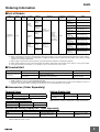
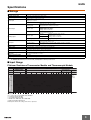
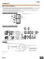
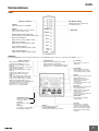
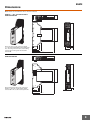
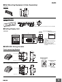
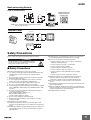
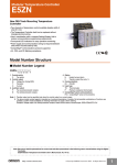
Modular Temperature Controller
E5ZN
CSM_E5ZN_DS_E_3_1
New DIN Track Mounting Temperature
Controller
• Two channels of temperature control available despite width of
only 22.5 mm.
• The Temperature Controller itself can be replaced without
changing terminal wiring.
• Use in combination with a compact Setting Display Unit to
reduce communications programming requirements.
• Front-panel LED indicators for easy operation monitoring.
• Power supply and communications wiring not required between
Units when mounted side-by-side.
• CompoWay/F communications protocol supported.
• UL, CSA, and CE Marking compliance.
Refer to Safety Precautions on page 11 to 12 and Safety
Precautions for All Temperature Controllers.
Model Number Structure
■ Model Number Legend
E5ZN-@@@@@@-@
1 2 3 4 5 6
7
1. Control points
2:
Two points
2. Control output
Q:
Voltage (for driving SSR)
T:
Transistor
C:
Current
3. Auxiliary output
P:
Two sourcing transistor outputs
N:
Two sinking transistor outputs
4. Option
H:
Heater burnout alarm
F:
Transfer output (See note 1.)
5. Communications
03: RS-485
6. Input type
TC: Thermocouple
P:
Platinum resistance thermometer
7. CompoWay/F serial communications
FLK: CompoWay/F serial communications
Note: 1. Transfer output can be specified only when the control output is a current output.
2. The above model number legend is intended as a functional description of models. Not all possible combinations of functions are
available. Confirm model availability in Ordering Information on page 2 when ordering.
Example: Voltage output, two sinking transistor outputs, heater burnout alarm, thermocouple: E5ZN-2TNH03TC-FLK
Note: Be sure to read the precautions for correct use and other precautions in the following user's manual before using the Digital
Controller.
E5ZN Modular Temperature Controller User’s Manual (Cat. No. H113)
1
E5ZN
Ordering Information
■ List of Models
Name
Power
supply
No. of
control
points
Control
output
Auxiliary
output
Voltage
output
(for SSRs)
Transistor
output
2
Communications functions
Input type (See
note 5.)
Model
Transistor
output: 2 pts
(sinking)
Thermocouple
E5ZN-2QNH03TC-FLK
Platinum
resistance
thermometer
E5ZN-2QNH03P-FLK
Transistor
output: 2 pts
(sourcing)
Thermocouple
E5ZN-2QPH03TC-FLK
Platinum
resistance
thermometer
E5ZN-2QPH03P-FLK
Thermocouple
E5ZN-2TNH03TC-FLK
Platinum
resistance
thermometer
E5ZN-2TNH03P-FLK
Thermocouple
E5ZN-2TPH03TC-FLK
Platinum
resistance
thermometer
E5ZN-2TPH03P-FLK
Thermocouple
E5ZN-2CNF03TC-FLK
Platinum
resistance
thermometer
E5ZN-2CNF03P-FLK
Thermocouple
E5ZN-2CPF03TC-FLK
Platinum
resistance
thermometer
E5ZN-2CPF03P-FLK
Transistor
output: 2 pts
(sinking)
Temperature
Controller (See 24 VDC
note 1.)
Functions
Transistor
output: 2 pts
(sourcing)
Transistor
Analog
output: 2 pts
output
(sinking)
(current
output)
(See note 2.)
Transistor
output: 2 pts
(sourcing)
Heater
burnout alarm
(See note 3.) Heating or
heat/cool
control is
selectable
(See note 4.)
RS-485
Event input: 1
point per Unit
Transfer output (linear
voltage output)
(See note 2.)
Note: 1. Terminal Units are required for wiring. Purchase separately.
2. When connecting the load of the controlled system, heat control output or cool control output can be allocated to the control output or
auxiliary output. When connecting a recording device or Digital Panel Meter, transfer output can be allocated to control output or auxiliary
output 3 or 4 of analog output models.
3. When using the heater burnout alarm, purchase a Current Transformer (E54-CT1 or E54-CT3) separately.
4. When using heating and cooling control functionality, the auxiliary output will be either heating control output or cooling control output.
5. Analog input and infrared temperature sensors (ES1B) can also be used with thermocouple models.
■ Terminal Unit
Name
No. of terminals
Terminal Unit
(Includes bus system without backplane.)
Functions
Model
24
Equipped with communications terminals for power supply, commuE5ZN-SCT24S-500
nications, and setting devices.
18 (See note 1.)
Not equipped with communications terminals for power supply,
communications, and setting devices.
E5ZN-SCT18S-500
Note: 1. When using 2 or more E5ZNs mounted side-by-side, use the E5ZN-SCT18S-500 for the second and subsequent Units. When using
E5ZNs separately, be sure to use the E5ZN-SCT24S-500.
2. Two End Plates are provided with a E5ZN-SCT24S-500 Terminal Unit. Up to 16 Terminal Units can be used to expand the system to a
maximum of 32 channels. When mounting to a DIN Track, be sure to mount End Plates on both sides.
■ Accessories (Order Separately)
Terminal Cover
Setting Display Unit
Model
E53-COV12
E53-COV13
Type
For SCT24S-500 models
For SCT18S-500 models
Name
Current Transformer (CT)
Setting Display Unit
(See note.)
Power supply
24 VDC
Model
E5ZN-SDL
Note: Purchase sockets for wiring (shown on page 2) separately.
Model
E54-CT1
E54-CT3
Diameter
5.8 dia.
12.0 dia.
Sockets (for Setting Display Unit - Order Separately)
Model
Type
P2CF-11
P2CF-11-E
Front-connecting socket
Front-connecting socket
(with finger protection)
P3GA-11
Y92A-48G
Back-connecting socket
Terminal cover for finger
protection
Note: Refer to the following manual for precautionary information and other information necessary to use the E5ZN: E5ZN Temperature Controller
Operation Manual (Cat. No. H113).
2
E5ZN
Specifications
■ Ratings
Power supply voltage
24 VDC
Allowable voltage range
85% to 110% of the rated power supply voltage
Power consumption
Approx. 3 W
Sensor input
Thermocouple: K, J, T, E, L, U, N, R, S, B
Infrared temperature sensor (ES1B series): 10 to 70°C, 60 to 120°C, 115 to 165°C, 140 to 260°C
Voltage input: 0 to 50 mV
Platinum resistance thermometer: Pt100, JPt100
Control output
Voltage output
(for driving SSR)
Output voltage: 12 VDC ±15% (PNP);
Maximum load current: 21 mA;
Equipped with short-circuit protection circuit
Transistor output
Maximum operational voltage: 30 VDC;
Maximum load current: 100 mA;
Residual voltage: 1.5 V max.;
Leakage current: 0.4 mA max.
Current output
Current output range: 4 to 20/0 to 20 mA DC;
Load: 350 Ω max. (See note 2.)
Sourcing
Maximum operating voltage: 30 VDC;
Maximum load current: 50 mA;
Residual voltage: 1.5 V max.;
Leakage current: 0.4 mA max.
Transistor output
Auxiliary output
Sinking
Linear voltage output
Event input
Voltage output range: 1 to 5/0 to 5 VDC;
Load: 10 kΩ min.
Contact output
ON: 1 kΩ max., OFF: 100 kΩ min.
Discharge current: Approx. 7 mA
Non-contact output
ON: Residual voltage: 1.5 V max., OFF: Leakage current: 0.1 mA max.
Discharge current: Approx. 7 mA
Number of input and control points
Input points: 2, Control points: 2
Setting method
Via communications or using the Setting Display Unit (E5ZN-SDL)
Control method
2-PID or ON/OFF control
Other functions
Heater burnout detection function, transfer output function
Multi-SP and RUN/STOP switching using event input
Ambient operating
temperature
−10 to 55°C (with no icing or condensation)
For 3 years of assured use: −10 to 50°C
Ambient operating humidity
25% to 85%
Storage temperature
−25 to 65°C (with no icing or condensation)
Note: 1. Do not use an inverter output for the power supply. (Refer to Safety Precautions for All Temperature Controllers.)
2. OMRON G32A-EA Cycle Controller Unit (load impedance 352 Ω) can be used.
■ Input Range
Platinum Resistance Thermometer Models and Thermocouple Models
Input type
Name
Platinum resistance
thermometer models
Platinum resistance
thermometer
Pt100
JPt100
Thermocouple models
Thermocouple
K
J
T
E
L
U
N
R
S
B
Infrared temperature
Analog input
sensor
10 to 60 to 115 to 160 to
70°C 120°C165°C 260°C 0 to 50 mV
Temperature range (°C)
1800
1800
1700 1700
1700
1600
1500
1400
1300
1300
1300
1200
1100
1000 850
850
850
900
800
700
600
600
500.0
500.0
500.0
500
400.0 400 400.0
400 400.0
400
300
200
100.0
100.0
100
100.0
0
0
0
0
0.0
0.0
−100
−20.0 −100 −20.0
−100
−200 −200 −199.9
−200 −199.9
−200 −199.9 −200
−200
−199.9
Setting
number
0
1
2
3
4
0
1
2
3
4
The applicable standards for the input types are as follows:
• K, J, T, E, N, R, S, B: JIS C1602-1995, IEC584-1
• L: Fe-CuNi, DIN 43710-1985
• U: Cu-CuNi, DIN 43710-1985
• JPt100: JIS C 1604-1989, JIS C 1606-1989
• Pt100: JIS C 1604-1997 IEC 751
Shaded parts indicate the settings at the time of purchase.
17
5
6
7
18
8
9
10
11
−1999 to
9999 or
−199.9 to
999.9
by scaling
260
120
165
0
0
0
0
12
13
14
15
90
16
3
E5ZN
■ Characteristics
Indication
accuracy
Influence of temperature
Influence of voltage
Thermocouple: (Indicated value ±0.5% or ±1°C, whichever is greater) ±1 digit max. (See note 1.)
Platinum resistance thermometer: (Indicated value ±0.5% or ±1°C, whichever is greater) ±1 digit max. (See note
1.)
Analog input: ±0.5% or ±1 digit max.
CT input: ±5% FS ±1 digit max.
Thermocouple input (R, S, B): (±1% of PV or ±10°C, whichever is greater) ±1 digit max.
Other thermocouple input: ( ±1% of PV or ±4°C, whichever is greater) ±1 digit max.
*K thermocouple at −100°C max.: ±10°C max.
Platinum resistance thermometer: (±1% of PV or ±2°C, whichever is greater) ±1 digit max.
Analog input: (±1%FS) ±1 digit max.
Transfer output
Accuracy: ±0.5% FS (See note 2.)
Hysteresis
0.1 to 999.9 EU (in units of 0.1 EU)
(See note 3.)
Proportional band (P)
0.1 to 999.9 EU (in units of 0.1 EU)
(See note 3.)
Integral time (I)
0 to 3,999 s (in units of 1 s)
Derivative time (D)
0 to 3,999 s (in units of 1 s)
Control period
1 to 99 s (in units of 1 s)
Manual reset value
0.0 to 100.0% (in units of 0.1%)
Alarm setting range
−1,999 to 9,999 (Position of decimal point depends on input type.)
Sampling period
500 ms
Insulation resistance
20 MΩ min. (at 500 VDC)
Dielectric strength
600 VAC for 1 minute at 50 or 60 Hz (between unlike terminals of charged parts)
Vibration resistance
10 to 55 Hz, 10 m/s2 for 2 h each in X, Y, and Z directions
Shock resistance
150 m/s2 max., 3 times each in ±X, ±Y, and ±Z directions
Weight
Temperature Controller: Approx. 90 g
Terminal Unit (18): Approx. 80 g
Terminal Unit (24): Approx. 100 g
Degree of protection
Temperature Controller: IP00
Terminal Unit: IP00
Memory protection
EEPROM (non-volatile memory) (Number of write operations: 100,000)
UL File No.:
CSA File No.:
CE EMS:
Approved standards
(See note 4.)
EMI:
E200593
203889-1140084
ESD
EN61326, EN61000-4-2 (4 kV/contact, 8 kV/air)
REM field
EN61326, EN61000-4-3 (10 V/m)
Fast transient
EN61326, EN61000-4-4 (2 kV/DC power, 1 kV/I/O)
Surge immunity EN61326, EN61000-4-5 (line to ground: 2 kV/DC power
1 kV/I/O
line to line:
1 kV/DC power)
Conducted RF EN61326, EN61000-4-6 (10 V)
Radiated
EN61326 Class A
Note: 1. The indication accuracy for T and N thermocouples at −100°C, and for U and L thermocouples is ±2°C ±1 digit max. There is no specification for the indication accuracy for the B thermocouple used at 400°C max. The indication accuracy for R and S thermocouples at
200°C max. is ±3°C ±1 digit max.
2. The transfer output accuracy for 0 to 4 mA when 0 to 20 mA DC is selected is ±0.5% FS +0.7 mA. The transfer output accuracy for 0 to
1 V when 0 to 5 VDC is selected is ±0.5% FS +0.175 V.
3. “EU” stands for “Engineering Unit.”
4. In order to satisfy the EN61326 Class A standard for conducted emissions, install a noise filter (Densei-Lambda MXB-1206-33 or equivalent) in a DC power line as close to the E5ZN as possible.
4
E5ZN
■ Communications
(Host Communications)
■ Current Transformer (CT) (Order
Separately)
Transmission line
connection method
RS-485 multipoint
Dielectric strength
1,000 VAC (1 minute)
Vibration resistance
50 Hz, 98 m/s2
Communications
method
RS-485 (2-wire, half-duplex)
Weight
E54-CT1: Approx. 11.5 g
E54-CT3: Approx. 50 g
Synchronization
method
Start-stop synchronization
Accessories
(E54-CT3 only)
Armature (2)
Plug (2)
Baud rate
4,800, 9,600, 19,200, or 38,400 bps
Transmission code
ASCII
Data bit length
(See note.)
7 or 8 bits
Stop bit length (See
note.)
Maximum heater
current
Single-phase, 50 A AC (See note 1.)
1 or 2 bits
Vertical parity (none, even, odd)
Input current
readout accuracy
±5% FS ±1 digit max.
Heater burnout
alarm setting range
0.0 to 50.0 A (in units of 0.1 A)
(See note 2.)
Error detection
BCC (block check character)
Flow control
None
Interface
RS-485
Retry function
None
Number of Units that
can be connected in
parallel
16 Units max. (32 channels)
Note: The baud rate, data bit length, stop bit length, and vertical parity can all be set independently as host communications settings.
: Default setting values
■ Setting Display Unit (Order
Separately)
Power supply voltage
24 VDC
Allowable voltage
range
85% to 110% of the rated power supply
voltage
Power consumption
Approx. 1 W
Display method
7-segment digital display and single-color
display
Ambient operating
temperature
−10 to 55°C (with no icing or condensation)
For 3 years of assured use: −10 to 50°C
■ Heater Burnout Alarm
Minimum detection ON
190 ms (See note 3.)
time
Note: 1. Use the K8AC-H Digital Heater Burnout Alarm Detector for
burnout detection of 3-phase heaters.
2. If the heater burnout alarm setting is set to 0.0 A, the alarm
is always OFF, and if it is set to 50.0 A the alarm is always
ON.
3. If the ON time for control output is less than 190 ms, heater
burnout detection and heater current measurement will not
be performed.
Ambient operating hu25% to 85%
midity
Storage temperature
−25 to 65°C (with no icing or condensation)
Communications
method
RS-485 (half-duplex)
Communications format
Special protocol
Insulation resistance
20 MΩ min. (at 500 VDC)
Dielectric strength
1,500 VAC for 1 minute at 50 or 60 Hz (between unlike terminals of charged parts)
Vibration resistance
10 to 55 Hz, 20 m/s2 for 2 h each in X, Y,
and Z directions
Shock resistance
300 m/s2 max., 3 times each in ±X, ±Y, and
±Z directions
Enclosure ratings
Front panel: IP50
Rear case: IP20
Terminal case: IP00
Memory protection
EEPROM (non-volatile memory) (Number
of writes: 100,000)
Weight
Approx. 100 g
Mounting bracket: Approx. 10 g
5
E5ZN
Installation
■ Connection Diagrams
• Voltage output (control output) is not electrically isolated from internal circuitry. Therefore, when using grounded thermocouples, do not ground
control output terminals. (Doing so may result in temperature measurement errors due to unwanted current paths.)
• There is basic insulation between the power supply inputs and outputs for this product. If reinforced insulation is required, connect the input and
output terminals to equipment without any exposed charge-carrying parts, or to equipment with basic insulation sufficient for the maximum
operating voltage of the power supply and the inputs and outputs.
• To comply with the standards for noise terminal voltage for class A in EN 61326, install a noise filter (Densei Lamda MXB-1206-33 or the
equivalent) to the DC power line as close as possible to the Temperature Controller.
Using with the E5ZN-SCT24S-500
Wiring for terminals 1 to 18 is the same as for the
E5ZN-SCT18-500. See below.
+
19
13
7
1
20
14
8
2
21
15
9
3
24-VDC input
power supply
−
B (+)
Terminals upward
Setting Display Unit
communications
A (−)
22
16
10
7
4
23
17
11
8
5
24
18
12
9
6
B (+)
Host communications
RS-485
A (−)
E5ZN-SCT24S
(TOP VIEW)
Using with the E5ZN-SCT18S-500
+
7
OUT1
1
4-20 mA DC/
0-20 mA DC
OUT2
+
4-20 mA DC/
0-20 mA DC
8 −
2 −
ch1
ch2
Current-output type
E5ZN-2C@F03@-FLK
13
13
13
7
7 +
1
Event input
14
SUB1
SUB2
15
COM
PNP (sourcing) type
E5ZN-2@P@03@-FLK
16
CT1
CT2
ch1
17
SUB1 14
SUB2
15
COM
−
16
1-5 VDC/
SUB3 0-5 -VDC
17 + 1-5 VDC/
SUB4
2
9
3
16
17
Contact
input
10
11
8
Noncontact
input
+
−
4
10
5
− 11
1 +
2
−
7
12 VDC
21 mA
OUT2
−
Voltage-output type
E5ZN-2Q@H03@-FLK
4
−
5
10
OUT2
8
2
ch1
ch2
Transistor-output type
E5ZN-2T@H03@-FLK
4
11
18
18 +
Analog-output type
(linear-voltage-output)
E5ZN-2C@F03@-FLK
12
6
E5ZN-SCT18S-500
+ 12
+ 6
ch1
ch2
Thermocouple/infrared
temperature sensor
10
−
5
12
6
ch1
ch2
Pt
1
OUT1
4
−
11
V
0-5 VDC
Voltage-output type
E5ZN-2Q@H03@-FLK
Transistor-output type
E5ZN-2T@H03@-FLK
8
NPN (sinking) type
E5ZN-2@N@03@-FLK
ch2
18
14
15
12 VDC
21 mA
OUT1
5
V
+ 12
ch1
+ 6
ch2
Analog input
E5ZN-SDL
When the E5ZN-SCT24S-500 is used
Do not use.
24 VDC input power supply
Connected to the E5ZN
Temperature Controller
Do not use.
Note: 1. Terminals 4 and 9, 7 and 11,
and 8 and 10 are connected
internally at the E5ZN-SDL
side.
2. Do not connect anything to
terminals 1, 2, 5, and 6.
Note: Purchase either a P2CF-11 or a P3GA-11 Socket separately. (Refer to pages 10 to 11.)
6
E5ZN
Nomenclature
E5ZN-2
Unit Number Setting
Setting range of 0 to F allows up
to 16 Units to be set.
Operation Indicators
POWER
Lights when power is turned ON.
ERROR
Lights when a fatal error (e.g., memory
error or sensor error) occurs.
SD/RD (Communications Operation)
Flashes during communications with the host.
OUT1 (Control Output 1)
Lights when the control output 1 is ON.
OUT2 (Control Output 2)
Lights when the control output 2 is ON.
POWER
Baud Rate
ERROR
SD/RD
OUT1
OUT2
SUB1
SUB1 (Auxiliary Output 1)
Lights when the auxiliary output 1 is ON.
SUB2
SUB2 (Auxiliary Output 2)
Lights when the auxiliary output 2 is ON.
E5ZN-SDL
The following diagram shows the names and functions of the E5ZN-SDL parts for when it is connected to the E5ZN-2@@@@@@@.
Operation Indicators
• These indicators indicate the terminal
operations for the E5ZN-2@@@@@@@.
• OUT1, OUT2 (Control Output 1, Control
Output 2)
Light when the control output 1 or the control
output 2 functions are ON.
• SUB1, SUB2 (Auxiliary Output 1, Auxiliary
Output 2)
Light when the auxiliary output 1 or the
auxiliary output 2 functions are ON.
• STOP
Lights when operation stops. Lights for an
event or when RUN/STOP is set to STOP
during control. Remains unlit at other times.
• CMW (Communications Write Control)
Lights when communications write is permitted
and remains unlit when it is prohibited.
• Some indicators are not used on the
E5ZN-2@@@@@@@ (SUB3, SUB4).
Unit/Channel Indicator
Indicates the unit number and
the channel number.
Level Key
Press this key to switch setting
levels.
Mode Key
Press this key to switch setting
data within the setting level.
Temperature Unit
Displayed when the display unit for setting
data is temperature. The display is
determined by the setting for temperature unit,
with either “°C” or “°F” displayed accordingly.
No. 1 Display
Displays the PV or the type of
setting data.
No. 2 Display
Displays the target value, the
control variable, or the set value
for setting data (setting contents).
Up Key
Each time this key is pressed, the
value displayed in No. 2
Display increases. If it is held
down, the rate of increase
becomes faster.
It can also be used to move to the
next setting item.
Down Key
Each time this key is pressed, the
value displayed in No. 2
Display decreases. If it is held
down, the rate of decrease
becomes faster.
It can also be used to return to the
previous setting item.
Channel Key
Press this key to change the
channel number.
UNIT Key
Press to switch the unit number.
Level Key and Mode Key
Press together to switch to protect mode.
Copy Key
Press this key to read all the
settings from the Temperature
Controller to the Setting Display
Unit, or to write from the Setting
Display Unit to the Temperature
Controller.
7
E5ZN
Dimensions
Note: All units are in millimeters unless otherwise indicated.
22.3
E5ZN-2@@@03@-FLK Connected to
E5ZN-SCT24S-500
UNIT
BPS
POWER
130
72.8
ERROR
SD/RD
OUT1
E5ZN-SCT24S
OUT2
SUB1
SUB2
E5ZN
27
35
4.7
When only using one Unit, purchase the E5ZN2@@@03@-FLK and the E5ZN-SCT24S-500 together.
Also, when using horizontal side-by-side mounting,
purchase the first Unit together with the E5ZNSCT24S-500.
30
46
112
E5ZN-2@@@03@-FLK Connected to
E5ZN-SCT18S-500
UNIT
BPS
POWER
130
72.8
ERROR
SD/RD
OUT1
OUT2
SUB1
SUB2
E5ZN
27
5.2
22.5
4.7
When mounting Units side-by-side, purchase the
E5ZN-2@@@03@-FLK together with the E5ZNSCT18S-500 for the second and subsequent Units.
35
46
112
8
E5ZN
■ End Plate
PFP-M
10
6.2
Eight, M4
pan-head
screws
1.8
1
50
35.5 35.3
1.8
11.5
10
1.3
4.8
M4 spring washer
Note: End Plates are provided with the E5ZN-SCT24-500.
Be sure to mount End Plates at both ends of Unit blocks.
■ Current Transformer (Order Separately)
E54-CT1
21
15
2.8
5.8 dia.
7.5
25
3
10.5
40
Two, 3.5 dia.
10
30
E54-CT3
E54-CT3 Accessories
2.36 dia.
Connection Example
• Armature
30
Armature
Plug
12 dia.
9
Approx.
3 dia.
Lead wire
40 × 40
18
Two, M3 (Depth: 4)
15
• Plug
Approx.
6 dia.
30
(22)
■ Terminal Cover (Order Separately)
E53-COV12
E53-COV13
26.8
19
29.8
26.8
19
22.3
9
E5ZN
■ Rail Mounting Equipment (Order Separately)
Spacer
PFP-S
16
12
5
34.8
44.3
16.5
Mounting Track
PFP-100N
PFP-50N
7.3±0.15
4.5
35±0.3
15
25
25
10
25
10
1000 (500) (See note.)
25
15 (5)
27±0.15
1
(See note.)
Note: The figures in parentheses are dimensions for the PFP-50N.
■ Setting Display Unit
E5ZN-SDL
Individual
Mounting
Panel Cutout Dimensions
Side-by-side Mounting
(48 × No. of Units – 2.5) +1.0
0
(84)
48 × 48
6
63.7
45 +0.6
0
45 +0.6
0
60 min.
44.8 × 44.8
45 +0.6
0
14.2
• The mounting panel thickness is 1
to 5 mm.
• Vertical side-by-side mounting is
not possible.
(Allow sufficient space above and
below.)
• When mounting several Units,
make sure that the ambient
temperature specifications are not
exceeded.
■ E5ZN-SDL Wiring Sockets
Front-connecting Sockets
P2CF-11 (Standard Model)
31.2 max.
50 max.
Two, 4.5-dia. holes
70 max.
35.4
Terminal Arrangement/
Internal Connections
(TOP VIEW)
4
7.8
Eleven, M3.5 × 7.5 Sems screws
4.5
3
8
7
6
5
4
Mounting Hole Cutout
Dimensions
Two, M4 or 4.5 dia.
P2F-11-E (with Finger Protection)
31.2 max.
50 max.
40±0.2
8
7
40±0.2
9
30
6
10
5
3
Two, 4.5-dia. holes
3
11
1
2
Note: DIN track
mounting is
also possible.
P2CF-11-E
4
70 max.
9
1.2
35.4
3
10A250VAC
RESISTIVE
10
11
Eleven, M3.5 × 7.5 set screws
1
4
2
7.8
5
4.5
10
E5ZN
Back-connecting Sockets
P3GA-11 (Standard Model)
4
27 dia.
7
Terminal Arrangement/
Internal Connections
(BOTTOM VIEW)
3
25.6
45
5
6
7
8
2
1
11 10
4
3
4.5
45
16.3
6.2
9
6
8.7
Note: Use in combination with a Terminal Cover (Y92A48G) for finger protection.
Terminal Cover
Twelve, 6.4 dia.
Y92A-48G
34
Y92A-48G
UP
@47.7
@48
P C
16.5
24.6
27.6
47.4
Safety Precautions
Refer to Safety Precautions for All Temperature Controllers.
!WARNING
Provide at least one power-interruption switch to
ensure that the power is OFF before wiring. Not
doing so may result in electric shock.
13.Install switches or circuit-breakers so that the user can turn the
power OFF immediately, and indicate these accordingly.
14.Do not use the product in the following locations:
• Locations subject to dust or corrosive gases (in particular,
sulfide gas and ammonia gas)
• Locations subject to freezing or condensation
• Locations exposed to direct sunlight
■ Safety Precautions
• Locations subject to vibrations or shocks
Observe the following points to ensure safe operation.
• Locations subject to heat radiated directly from heating
equipment
1. Use and store the product within the specified temperature and
humidity ranges. Cool the product (e.g., using fans) where
necessary.
2. Do not touch the electronic components or pattern of the PCB.
Hold the product by the case.
3. To ensure proper heat dissipation, leave a space around the
product. Do not block the product’s ventilating holes.
4. Use at the rated power supply voltage with the rated load.
5. Be sure to connect terminals with the correct polarity.
6. Perform wiring using crimp terminals of the specified size. (E5ZNSCT@S-500: M3.0, width 5.8 mm max.; E5ZN-SDL: M3.5, width
7.2 max.)
7. Be sure to use wires satisfying the following specifications for
connection using bare wires.
Power supply terminals: AWG 22 to 14
Other terminals: AWG 28 to 16
(Length of exposed part: 6 to 8 mm)
8. Do not connect anything to unused terminals.
9. Ensure that the rated voltage is reached within 2 seconds of
turning power ON.
10.Allow 30 seconds’ warm-up time.
11.Install the product as far away as possible from devices that
generate strong, high-frequency noise and devices that generate
surges.
12.Keep wiring separate from high-voltage power lines or power lines
carrying large currents. Do not wire in parallel with or together
with power lines.
• Locations subject to exposure to water or oil
• Locations subject to intense temperature changes
15.When the Terminal Unit is separated from the Temperature
Controller, under no circumstances touch the electrical
components or apply shock to the Temperature Controller.
16.Do not use solvents to clean the product. Use commercial
alcohol.
17.After wiring is completed remove the dust-protection label to allow
proper heat dissipation.
18.When mounting the Temperature Controller to the Terminal Unit,
make sure that the hook on the side of the Temperature Controller
facing the Terminal Unit is inserted properly.
19.Install the DIN track vertically.
11
E5ZN
■ Precautions for Correct Use
Service Life
Use within the following temperature and humidity ranges:
• Temperature: −10 to 55°C (with no icing or condensation)
• Humidity: 25% to 85%
If the product is installed inside a control panel, the temperature
around the product (and not the temperature around the control
panel) must be kept below 55°C.
With electronic devices like the E5ZN, the service life will depend not
only on the number of switching operations performed by the relay
but also on the service life of the internal electronic components. The
service life of these components depends on the ambient
temperature; it will be shorter if the ambient temperature is high, and
longer if the ambient temperature is low. For this reason, the service
life of the product can be lengthened by keeping the inside of the
E5ZN at a low temperature.
Operating Precautions
1. A time of approximately 4 s is required after the power supply is
turned ON until the outputs turn ON. Take this time into
consideration when the Temperature Controller is incorporated in
a sequence circuit.
2. Using the product near radios, televisions, or other wireless
devices may result in reception interference.
Mounting and Dismounting
• To mount using a mounting track, first hook part A (see below) onto
the track and then push down on part B.
If several Units are mounted side-by-side or are arranged vertically,
the heat generated may cause the internal temperature of the Units
to rise, reducing service life. To prevent this, take steps to ensure that
the Units are cooled, such as installing fans.
Ensure, however, that the terminals are not also cooled, otherwise
correct temperature measurement will not be possible.
Measurement Accuracy
• To dismount, insert a flat-bladed screwdriver into part C, pull the
hook down, and then lift the bottom part of the E5ZN upwards.
When extending the lead wires for thermocouples, use a
compensating conductor appropriate for the type of thermocouple
used.
When extending the lead wires for platinum resistance
thermometers, use lead wires with a low resistance, and make the
resistance in the 3 lead wires equal.
Make sure that the temperature sensor type and the input type of the
E5ZN are the same.
Mount the E5ZN horizontally.
If significant errors occur, check that input compensation has been
set correctly.
Waterproofing
30 mm min.
The degree of protection is given below. Parts for which the degree of
protection is not clearly indicated, and parts with IP@0 ratings (where
@ is not 0) do not have waterproof specifications.
• Temperature Controller: IP00
• Terminal Unit: IP00
Stopper
• Mount the E5ZN at least 30 mm away from other devices to ensure
easy mounting and dismounting.
ALL DIMENSIONS SHOWN ARE IN MILLIMETERS.
To convert millimeters into inches, multiply by 0.03937. To convert grams into ounces, multiply by 0.03527.
In the interest of product improvement, specifications are subject to change without notice.
12
Read and Understand This Catalog
Please read and understand this catalog before purchasing the products. Please consult your OMRON representative if you have any questions or
comments.
Warranty and Limitations of Liability
WARRANTY
OMRON's exclusive warranty is that the products are free from defects in materials and workmanship for a period of one year (or other period if specified)
from date of sale by OMRON.
OMRON MAKES NO WARRANTY OR REPRESENTATION, EXPRESS OR IMPLIED, REGARDING NON-INFRINGEMENT, MERCHANTABILITY, OR
FITNESS FOR PARTICULAR PURPOSE OF THE PRODUCTS. ANY BUYER OR USER ACKNOWLEDGES THAT THE BUYER OR USER ALONE HAS
DETERMINED THAT THE PRODUCTS WILL SUITABLY MEET THE REQUIREMENTS OF THEIR INTENDED USE. OMRON DISCLAIMS ALL OTHER
WARRANTIES, EXPRESS OR IMPLIED.
LIMITATIONS OF LIABILITY
OMRON SHALL NOT BE RESPONSIBLE FOR SPECIAL, INDIRECT, OR CONSEQUENTIAL DAMAGES, LOSS OF PROFITS OR COMMERCIAL LOSS
IN ANY WAY CONNECTED WITH THE PRODUCTS, WHETHER SUCH CLAIM IS BASED ON CONTRACT, WARRANTY, NEGLIGENCE, OR STRICT
LIABILITY.
In no event shall the responsibility of OMRON for any act exceed the individual price of the product on which liability is asserted.
IN NO EVENT SHALL OMRON BE RESPONSIBLE FOR WARRANTY, REPAIR, OR OTHER CLAIMS REGARDING THE PRODUCTS UNLESS
OMRON'S ANALYSIS CONFIRMS THAT THE PRODUCTS WERE PROPERLY HANDLED, STORED, INSTALLED, AND MAINTAINED AND NOT
SUBJECT TO CONTAMINATION, ABUSE, MISUSE, OR INAPPROPRIATE MODIFICATION OR REPAIR.
Application Considerations
SUITABILITY FOR USE
OMRON shall not be responsible for conformity with any standards, codes, or regulations that apply to the combination of products in the customer's
application or use of the products.
At the customer's request, OMRON will provide applicable third party certification documents identifying ratings and limitations of use that apply to the
products. This information by itself is not sufficient for a complete determination of the suitability of the products in combination with the end product,
machine, system, or other application or use.
The following are some examples of applications for which particular attention must be given. This is not intended to be an exhaustive list of all possible
uses of the products, nor is it intended to imply that the uses listed may be suitable for the products:
• Outdoor use, uses involving potential chemical contamination or electrical interference, or conditions or uses not described in this catalog.
• Nuclear energy control systems, combustion systems, railroad systems, aviation systems, medical equipment, amusement machines, vehicles,
safety equipment, and installations subject to separate industry or government regulations.
• Systems, machines, and equipment that could present a risk to life or property.
Please know and observe all prohibitions of use applicable to the products.
NEVER USE THE PRODUCTS FOR AN APPLICATION INVOLVING SERIOUS RISK TO LIFE OR PROPERTY WITHOUT ENSURING THAT THE
SYSTEM AS A WHOLE HAS BEEN DESIGNED TO ADDRESS THE RISKS, AND THAT THE OMRON PRODUCTS ARE PROPERLY RATED AND
INSTALLED FOR THE INTENDED USE WITHIN THE OVERALL EQUIPMENT OR SYSTEM.
PROGRAMMABLE PRODUCTS
OMRON shall not be responsible for the user's programming of a programmable product, or any consequence thereof.
Disclaimers
CHANGE IN SPECIFICATIONS
Product specifications and accessories may be changed at any time based on improvements and other reasons.
It is our practice to change model numbers when published ratings or features are changed, or when significant construction changes are made.
However, some specifications of the products may be changed without any notice. When in doubt, special model numbers may be assigned to fix or
establish key specifications for your application on your request. Please consult with your OMRON representative at any time to confirm actual
specifications of purchased products.
DIMENSIONS AND WEIGHTS
Dimensions and weights are nominal and are not to be used for manufacturing purposes, even when tolerances are shown.
PERFORMANCE DATA
Performance data given in this catalog is provided as a guide for the user in determining suitability and does not constitute a warranty. It may represent the
result of OMRON’s test conditions, and the users must correlate it to actual application requirements. Actual performance is subject to the OMRON
Warranty and Limitations of Liability.
ERRORS AND OMISSIONS
The information in this document has been carefully checked and is believed to be accurate; however, no responsibility is assumed for clerical,
typographical, or proofreading errors, or omissions.
2010.6
In the interest of product improvement, specifications are subject to change without notice.
OMRON Corporation
Industrial Automation Company
http://www.ia.omron.com/
(c)Copyright OMRON Corporation 2010 All Right Reserved.