1
TOSHIBA Satellite L30 /
Satellite Pro L30 Series
User's Manual
TOSHIBA Satellite L30 / Satellite Pro L30 Series
Copyright
© 2006 by TOSHIBA Corporation. All rights reserved. Under the copyright
laws, this manual cannot be reproduced in any form without the prior
written permission of TOSHIBA. No patent liability is assumed, with respect
to the use of the information contained herein.
TOSHIBA Satellite L30 / Satellite Pro L30 Series Portable Personal
Computer User's Manual
First edition April 2006
Ownership and copyright of music, video, computer programs, databases,
etc. are protected by the copyright laws. These copyrighted materials may
be copied for private use at home only. If, beyond the limitation above, you
copy (including to transform data formats) or modify these materials,
transfer them or distribute them via the Internet without approval of
copyright owners, you may be subject to claims for compensation for
damage and/or criminal penalties due to infringements of copyrights or
personal rights. Please remember to observe the copyright laws when you
use this product to copy the copyrighted works or perform other actions.
Please note that you may infringe the owner's rights protected by the
copyright laws if you use the screen mode switching functions (e.g. Wide
mode, Wide Zoom mode, etc.) of this product to display enlarged images/
video at coffee shops or hotels for the purposes of profits or providing these
to the public.
This product incorporates copyright protection technology that is protected
by U.S. patents and other intellectual property rights. Use of this copyright
protection technology must be authorized by Macrovision, and is intended
for home and other limited viewing uses only unless otherwise authorized
by Macrovision. Reverse engineering or disassembly is prohibited.
Disclaimer
This manual has been validated and reviewed for accuracy. The
instructions and descriptions it contains are accurate for the TOSHIBA
Satellite L30 / Satellite Pro L30 Series Portable Personal Computer at the
time of this manual’s production. However, succeeding computers and
manuals are subject to change without notice. TOSHIBA assumes no
liability for damages incurred directly or indirectly from errors, omissions or
discrepancies between the computer and the manual.
ii
User’s Manual
TOSHIBA Satellite L30 / Satellite Pro L30 Series
Trademarks
Intel, Centrino, Intel Core and Celeron are trademarks or registered
trademarks of Intel Corporation or its subsidiaries in the United States and
other countries.
Windows® and Microsoft are registered trademarks of Microsoft
Corporation.
Photo CD is a trademark of Eastman Kodak.
TruSurround XT, WOW XT, SRS and
symbol are trademarks of SRS
Labs, Inc.
TruSurround XT, WOW XT, TruBass, SRS 3D and FOCUS technologies
are incorporated under license from SRS Labs, Inc.
Other trademarks and registered trademarks not listed above may be used
in this manual.
FCC information
Product Name: TOSHIBA Satellite L30 / Satellite Pro L30 Series
Model number: PSL3
FCC notice “Declaration of Conformity Information”
This equipment has been tested and found to comply with the limits for a
Class B digital device, pursuant to part 15 of the FCC rules. These limits
are designed to provide reasonable protection against harmful interference
in a residential installation. This equipment generates, uses and can radiate
radio frequency energy and, if not installed and used in accordance with the
instructions, may cause harmful interference to radio communications.
However, there is no guarantee that interference will not occur in a
particular installation. If this equipment does cause harmful interference to
radio or television reception, which can be determined by turning the
equipment off and on, the user is encouraged to try to correct the
interference by one or more of the following measures:
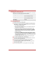
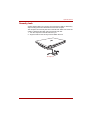
■ Reorient or relocate the receiving antenna.
■ Increase the separation between the equipment and receiver.
■ Connect the equipment into an outlet on a circuit different from that to
which the receiver is connected.
■ Consult the dealer or an experienced radio/TV technician for help.
User’s Manual
iii
TOSHIBA Satellite L30 / Satellite Pro L30 Series
Only peripherals complying with the FCC class B limits may be attached to
this equipment. Operation with non-compliant peripherals or peripherals
not recommended by TOSHIBA is likely to result in interference to radio
and TV reception. Shielded cables must be used between the external
devices and the computer’s external monitor port, USB port, serial port,
parallel port, PS/2 mouse/keyboard port and microphone jack. Changes or
modifications made to this equipment, not expressly approved by
TOSHIBA or parties authorized by TOSHIBA could void the user’s
authority to operate the equipment.
FCC conditions
This device complies with part 15 of the FCC Rules. Operation is subject to
the following two conditions:
1. This device may not cause harmful interference.
2. This device must accept any interference received, including
interference that may cause undesired operation.
Contact
Address:
TOSHIBA America Information Systems, Inc.
9740 Irvine Boulevard
Irvine, California 92618-1697
Telephone:
(949) 583-3000
EU Declaration of Conformity
TOSHIBA declares, that the product: TOSHIBA Satellite L30 / Satellite Pro
L30 Series conforms to the following Standards:
Supplementary
“The product complies with the requirements of
Information:
the Low Voltage Directive 73/23/EEC, the EMC
Directive 89/336/EEC and/or the R&TTE Directive
1999/5/EC.”
This product is carrying the CE-Mark in accordance with the related
European Directives. Responsible for CE-Marking is TOSHIBA Europe,
Hammfelddamm 8, 41460 Neuss, Germany.
iv
User’s Manual
TOSHIBA Satellite L30 / Satellite Pro L30 Series
VCCI Class B Information
Canadian Regulatory Information (Canada Only)
This digital apparatus does not exceed the Class B limits for radio noise
emissions from digital apparatus as set out in the Radio Interference
Regulation of the Canadian Department of Communications.
Note that Canadian Department of Communications (DOC) regulations
provide, that changes or modifications not expressly approved by
TOSHIBA Corporation could void your authority to operate this equipment.
This Class B digital apparatus meets all requirements of the Canadian
Interference-Causing Equipment Regulations.
Cet appareil numérique de la class B respecte toutes les exgences du
Règlement sur le matériel brouileur du Canada.
Modem warning notice
Conformity Statement
The equipment has been approved to [Council Decision 98/482/EC - "TBR
21"] for pan-European single terminal connection to the Public Switched
Telephone Network (PSTN).
However, due to differences between the individual PSTNs provided in
different countries/regions the approval does not, of itself, give an
unconditional assurance of successful operation on every PSTN network
termination point.
In the event of problems, you should contact your equipment supplier in the
first instance.
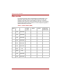
Network Compatibility Statement
This product is designed to work with, and is compatible with the following
networks. It has been tested to and found to conform with the additional
requirements conditional in EG 201 121.
User’s Manual
Germany
ATAAB AN005, AN006, AN007, AN009, AN010 and
DE03, 04, 05, 08, 09,12,14,17
Greece
ATAAB AN005, AN006 and GR01, 02, 03, 04
Portugal
ATAAB AN001, 005, 006, 007, 011 and P03, 04, 08,
10
v
TOSHIBA Satellite L30 / Satellite Pro L30 Series
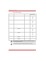
Spain
ATAAB AN005, 007, 012, and ES01
Switzerland
ATAAB AN002
All other countries/
regions
ATAAB AN003, 004
Specific switch settings or software setup are required for each network,
please refer to the relevant sections of the user guide for more details.
The hookflash (timed break register recall) function is subject to separate
national type approvals. It has not been tested for conformity to national
type regulations, and no guarantee of successful operation of that specific
function on specific national networks can be given.
Pursuant to FCC CFR 47, Part 68:
When you are ready to install or use the modem, call your local telephone
company and give them the following information:
■ The telephone number of the line to which you will connect the modem.
■ The registration number that is located on the device The FCC
registration number of the modem will be found on either the device
which is to be installed, or, if already installed, on the bottom of the
computer outside of the main system label.
■ The Ringer Equivalence Number (REN) of the modem, which can vary.
For the REN of your modem, refer to your modem’s label.
The modem connects to the telephone line by means of a standard jack
called the USOC RJ11C.
Type of service
Your modem is designed to be used on standard-device telephone lines.
Connection to telephone company-provided coin service (central office
implemented systems) is prohibited. Connection to party lines service is
subject to state tariffs.
If you have any questions about your telephone line, such as how many
pieces of equipment you can connect to it, the telephone company will
provide this information upon request.
Telephone company procedures
The goal of the telephone company is to provide you with the best service it
can. In order to do this, it may occasionally be necessary for them to make
changes in their equipment, operations, or procedures. If these changes
might affect your service or the operation of your equipment, the telephone
company will give you notice in writing to allow you to make any changes
necessary to maintain uninterrupted service.
vi
User’s Manual
TOSHIBA Satellite L30 / Satellite Pro L30 Series
If problems arise
If any of your telephone equipment is not operating properly, you should
immediately remove it from your telephone line, as it may cause harm to
the telephone network. If the telephone company notes a problem, they
may temporarily discontinue service. When practical, they will notify you in
advance of this disconnection. If advance notice is not feasible, you will be
notified as soon as possible. When you are notified, you will be given the
opportunity to correct the problem and informed of your right to file a
complaint with the FCC. In the event repairs are ever needed on your
modem, they should be performed by TOSHIBA Corporation or an
authorized representative of TOSHIBA Corporation.
Disconnection
If you should ever decide to permanently disconnect your modem from its
present line, please call the telephone company and let them know of this
change.
Fax branding
The Telephone Consumer Protection Act of 1991 makes it unlawful for any
person to use a computer or other electronic device to send any message
via a telephone fax machine unless such message clearly contains in a
margin at the top or bottom of each transmitted page or on the first page of
the transmission, the date and time it is sent and an identification of the
business, other entity or individual sending the message and the telephone
number of the sending machine or such business, other entity or individual.
In order to program this information into your fax modem, you should
complete the setup of your fax software before sending messages.
Instructions for IC CS-03 certified equipment
1. The Industry Canada label identifies certified equipment. This
certification means that the equipment meets certain
telecommunications network protective, operational and safety
requirements as prescribed in the appropriate Terminal Equipment
Technical Requirements document(s). The Department does not
guarantee the equipment will operate to the user’s satisfaction.
Before installing this equipment, users should ensure that it is
permissible to be connected to the facilities of the local
telecommunications company. The equipment must also be installed
using an acceptable method of connection.
The customer should be aware that compliance with the above
conditions may not prevent degradation of service in some situations.
Repairs to certified equipment should be coordinated by a
representative designated by the supplier. Any repairs or alterations
made by the user to this equipment, or equipment malfunctions, may
give the telecommunications company cause to request the user to
disconnect the equipment.
User’s Manual
vii
TOSHIBA Satellite L30 / Satellite Pro L30 Series
Users should ensure for their own protection that the electrical ground
connections of the power utility, telephone lines and internal metallic
water pipe system, if present, are connected together. This precaution
may be particularly important in rural areas.
Users should not attempt to make such connections themselves, but
should contact the appropriate electric inspection authority, or electrician,
as appropriate.
2. The user manual of analog equipment must contain the equipment’s
Ringer Equivalence Number (REN) and an explanation notice similar to
the following:
The Ringer Equivalence Number (REN) of the modem, which can vary.
For the REN of your modem, refer to your modem’s label.
The Ringer Equivalence Number (REN) assigned to each terminal device
provides an indication of the maximum number of terminals allowed to be
connected to a telephone interface. The termination on an interface may
consist of any combination of devices subject only to the requirement that
the sum of the Ringer Equivalence Numbers of all the devices does not
exceed 5.
3. The standard connecting arrangement (telephone jack type) for this
equipment is jack type(s): USOC RJ11C.
The IC registration number of the modem is shown below.
IC: 4005B-DELPHI
Notes for Users in Australia and New Zealand
Modem warning notice for Australia
Modems connected to the Australian telecoms network must have a valid
Austel permit. This modem has been designed to specifically configure to
ensure compliance with Austel standards when the country/region selection
is set to Australia. The use of other country/region setting while the modem
is attached to the Australian PSTN would result in you modem being
operated in a non-compliant manner. To verify that the country/region is
correctly set, enter the command ATI9 which displays the currently active
setting.
To set the country/region permanently to Australia, enter the following
command sequence:
AT+GCI=09
Failure to set the modem to the Australia country/region setting as shown
above will result in the modem being operated in a non-compliant manner.
Consequently, there would be no permit in force for this equipment and the
Telecoms Act 1991 prescribes a penalty of $12,000 for the connection of
non-permitted equipment.
viii
User’s Manual
TOSHIBA Satellite L30 / Satellite Pro L30 Series
Notes for use of this device in New Zealand
■ The grant of a Telepermit for a device in no way indicates Telecom
acceptance of responsibility for the correct operation of that device
under all operating conditions. In particular the higher speeds at which
this modem is capable of operating depend on a specific network
implementation which is only one of many ways of delivering high
quality voice telephony to customers. Failure to operate should not be
reported as a fault to Telecom.
■ In addition to satisfactory line conditions a modem can only work
properly if:
a/ it is compatible with the modem at the other end of the call and
b/ the application using the modem is compatible with the application
at the other end of the call - e.g., accessing the Internet requires
suitable software in addition to a modem.
■ This equipment shall not be used in any manner which could constitute
a nuisance to other Telecom customers.
■ Some parameters required for compliance with Telecom’s PTC
Specifications are dependent on the equipment (PC) associated with
this modem. The associated equipment shall be set to operate within
the following limits for compliance with Telecom Specifications:
a/ There shall be no more than 10 call attempts to the same number
within any 30 minute period for any single manual call initiation, and
b/ The equipment shall go on-hook for a period of not less than 30
seconds between the end of one attempt and the beginning of the
next.
c/ Automatic calls to different numbers shall be not less than 5
seconds apart.
■ Immediately disconnect this equipment should it become physically
damaged, and arrange for its disposal or repair.
■ The correct settings for use with this modem in New Zealand are as
follows:
ATB0 (CCITT operation)
AT&G2 (1800 Hz guard tone)
AT&P1 (Decadic dialling make-break ratio = 33%/67%)
ATS0=0 (not auto answer)
ATS10=less than 150 (loss of carrier to hang up delay, factory default of
15 recommended)
ATS11=90 (DTMF dialling on/off duration=90 ms)
ATX2 (Dial tone detect, but not (U.S.A.) call progress detect)
User’s Manual
ix
TOSHIBA Satellite L30 / Satellite Pro L30 Series
■ When used in the Auto Answer mode, the S0 register must be set with a
value of 3 or 4. This ensures:
■ a person calling your modem will hear a short burst of ringing before
the modem answers. This confirms that the call has been
successfully switched through the network.
■ caller identification information (which occurs between the first and
second ring cadences) is not destroyed.
■ The preferred method of dialling is to use DTMF tones (ATDT...) as this
is faster and more reliable than pulse (decadic) dialling. If for some
reason you must use decadic dialling, your communications program
must be set up to record numbers using the following translation table
as this modem does not implement the New Zealand “Reverse dialling”
standard.
Number to be dialled: 0 1 2 3 4 5 6 7 8 9
Number to program into computer: 0 9 8 7 6 5 4 3 2 1
Note that where DTMF dialling is used, the numbers should be entered
normally.
■ The transmit level from this device is set at a fixed level and because of
this there may be circumstances where the performance is less than
optimal. Before reporting such occurrences as faults, please check the
line with a standard Telepermitted telephone, and only report a fault if
the phone performance is impaired.
■ It is recommended that this equipment be disconnected from the
Telecom line during electrical storms.
■ When relocating the equipment, always disconnect the Telecom line
connection before the power connection, and reconnect the power first.
■ This equipment may not be compatible with Telecom Distinctive Alert
cadences and services such as FaxAbility.
NOTE THAT FAULT CALLOUTS CAUSED BY ANY OF THE ABOVE
CAUSES MAY INCUR A CHARGE FROM TELECOM
General conditions
As required by PTC 100, please ensure that this office is advised of any
changes to the specifications of these products which might affect
compliance with the relevant PTC Specifications.
The grant of this Telepermit is specific to the above products with the
marketing description as stated on the Telepermit label artwork. The
Telepermit may not be assigned to other parties or other products without
Telecom approval.
A Telepermit artwork for each device is included from which you may
prepare any number of Telepermit labels subject to the general instructions
on format, size and colour on the attached sheet.
The Telepermit label must be displayed on the product at all times as proof
to purchasers and service personnel that the product is able to be
legitimately connected to the Telecom network.
The Telepermit label may also be shown on the packaging of the product
and in the sales literature, as required in PTC 100.
x
User’s Manual
TOSHIBA Satellite L30 / Satellite Pro L30 Series
The charge for a Telepermit assessment is $337.50. An additional charge
of $337.50 is payable where an assessment is based on reports against
non-Telecom New Zealand Specifications. $112.50 is charged for each
variation when submitted at the same time as the original.
An invoice for $NZ1237.50 will be sent under separate cover.
Following information is only for EU-member states:
The symbol indicates that this product may not be treated as
household waste. Please ensure this product is properly
disposed as inappropriate waste handling of this product may
cause potential hazards to the environment and human health.
For more detailed information about recycling of this product,
please contact your local city office, your household waste
disposal service or the shop where you purchased the product.
This symbol may not stick depending on the country and region where you
purchased.
Optical disc drive safety instructions
Be sure to check the international precautions at the end of this section.
User’s Manual
xi
TOSHIBA Satellite L30 / Satellite Pro L30 Series
TEAC
CD-ROM Drive CD-224E
■ The CD-ROM drive employs a laser system. To ensure proper use of
this product, please read this instruction manual carefully and retain for
future reference. Should the unit ever require maintenance, contact an
authorized service location.
■ Use of controls, adjustments or the performance of procedures other
than those specified may result in hazardous radiation exposure.
■ To prevent direct exposure to the laser beam, do not try to open the
enclosure.
xii
User’s Manual
TOSHIBA Satellite L30 / Satellite Pro L30 Series
TEAC
CD-RW/DVD-ROM Drive DW-224E
■ The CD-RW & DVD-ROM drive employs a laser system. To ensure
proper use of this product, please read this instruction manual carefully
and retain for future reference. Should the unit ever require
maintenance, contact an authorized service location.
■ Use of controls, adjustments or the performance of procedures other
than those specified may result in hazardous radiation exposure.
■ To prevent direct exposure to the laser beam, do not try to open the
enclosure.
User’s Manual
xiii
TOSHIBA Satellite L30 / Satellite Pro L30 Series
Hitachi-LG Data Storage, Inc.
CD-RW/DVD-ROM Drive GCC-4244
■ The CD-RW & DVD-ROM drive employs a laser system. To ensure
proper use of this product, please read this instruction manual carefully
and retain for future reference. Should the unit ever require
maintenance, contact an authorized service location.
■ Use of controls, adjustments or the performance of procedures other
than those specified may result in hazardous radiation exposure.
■ To prevent direct exposure to the laser beam, do not try to open the
enclosure.
xiv
User’s Manual
TOSHIBA Satellite L30 / Satellite Pro L30 Series
TOSHIBA SAMSUNG STORAGE TECHNOLOGY
CD-RW/DVD-ROM Drive TS-L462C
■ The CD-RW & DVD-ROM drive employs a laser system. To ensure
proper use of this product, please read this instruction manual carefully
and retain for future reference. Should the unit ever require
maintenance, contact an authorized service location.
■ Use of controls, adjustments or the performance of procedures other
than those specified may result in hazardous radiation exposure.
■ To prevent direct exposure to the laser beam, do not try to open the
enclosure.
User’s Manual
xv
TOSHIBA Satellite L30 / Satellite Pro L30 Series
Panasonic
DVD-ROM & CD-R/RW Drive UJDA770T
■ The DVD-ROM & CD-R/RW drive employs a laser system. To ensure
proper use of this product, please read this instruction manual carefully
and retain for future reference. Should the unit ever require
maintenance, contact an authorized service location.
■ Use of controls, adjustments or the performance of procedures other
than those specified may result in hazardous radiation exposure.
■ To prevent direct exposure to the laser beam, do not try to open the
enclosure.
xvi
User’s Manual
TOSHIBA Satellite L30 / Satellite Pro L30 Series
International precautions
CAUTION: This appliance contains a laser
system and is classified as a "CLASS 1
LASER PRODUCT." To use this model
properly, read the instruction manual
carefully and keep this manual for your
future reference. In case of any trouble
with this model, please contact your
nearest "AUTHORIZED service station."
To prevent direct exposure to the laser
beam, do not try to open the enclosure.
VORSICHT: Dieses Gerät enthält ein
Laser-System und ist als
"LASERSCHUTZKLASSE 1 PRODUKT"
klassifiziert. Für den richtigen Gebrauch
dieses Modells lesen Sie bitte die
Bedienungsanleitung sorgfältig durch und
bewahren diese bitte als Referenz auf.
Falls Probleme mit diesem Modell
auftreten, benachrichtigen Sie bitte die
nächste "autorisierte Service-Vertretung".
Um einen direkten Kontakt mit dem
Laserstrahl zu vermeiden darf das Gerät
nicht geöffnet werden.
ADVARSEL: Denne mærking er anbragt
udvendigt på apparatet og indikerer, at
apparatet arbejder med laserstråler af
klasse 1, hviket betyder, at der anvendes
laserstrlier af svageste klasse, og at man
ikke på apparatets yderside kan bilve
udsat for utilladellg kraftig stråling.
APPARATET BOR KUN ÅBNES AF
FAGFOLK MED SÆRLIGT KENDSKAB
TIL APPARATER MED LASERSTRÅLER!
Indvendigt i apparatet er anbragt den her
gengivne advarselsmækning, som advarer
imod at foretage sådanne indgreb i
apparatet, at man kan komme til at udsatte
sig for laserstråling.
User’s Manual
xvii
TOSHIBA Satellite L30 / Satellite Pro L30 Series
OBS! Apparaten innehåller
laserkomponent som avger laserstråining
överstigande gränsen för laserklass 1.
VAROITUS. Suojakoteloa si saa avata.
Laite sisältää laserdiodin, joka lähetää
näkymätöntä silmilie vaarallista
lasersäteilyä.
CAUTION: USE OF CONTROLS OR
ADJUSTMENTS OR PERFORMANCE
OF PROCEDURES OTHER THAN
THOSE SPECIFIED IN THE OWNER’S
MANUAL MAY RESULT IN HAZARDOUS
RADIATION EXPOSURE.
VORSICHT: DIE VERWENDUNG VON
ANDEREN STEURUNGEN ODER
EINSTELLUNGEN ODER DAS
DURCHFÜHREN VON ANDEREN
VORGÄNGEN ALS IN DER
BEDIENUNGSANLEITUNG
BESCHRIEBEN KÖNNEN
GEFÄHRLICHE
STRAHLENEXPOSITIONEN ZUR
FOLGE HABEN.
xviii
User’s Manual
TOSHIBA Satellite L30/ Satellite Pro L30 Series
General Precautions
TOSHIBA computers are designed to optimize safety, minimize strain and
withstand the rigours of portability. However, certain precautions should be
observed to further reduce the risk of personal injury or damage to the
computer.
Be certain to read the general precautions below and to note the cautions
included in the text of the manual. Please also refer to the Safety
Instruction Manual.
Stress injury
Carefully read the Safety Instruction Manual. It contains information on the
prevention of stress injuries from your hands and wrists that can be caused
by extensive keyboard use. Chapter 3, Getting Started, also includes
information on workspace design, posture and lighting that can help reduce
physical stress.
Heat warning
■ Avoid prolonged physical contact with the computer. If the computer is
used for long periods, its surface can become very warm. While the
temperature will not feel hot to the touch, if you maintain physical
contact with the computer for a long time (if you rest the computer on
your lap, or if you keep your hands on the palm rest, for example) your
skin might suffer low-heat injury.
■ If the computer has been used for a long time, avoid direct contacting
with the metal plate supporting the I/O ports. It can become hot.
■ The surface of the AC adaptor can become hot when in use. This
condition does not indicate a malfunction. If you need to transport the
AC adaptor, disconnect it and let it cool before moving it.
■ Do not lay the AC adaptor on a material that is sensitive to heat. The
material could be damaged.
User’s Manual
xix
General Precautions
Pressure or impact damage
Do not apply heavy pressure to the computer or subject it to strong impact.
Excessive pressure or impact can cause damage to computer components
or otherwise cause malfunctions.
PC Card overheating
Some PC Cards can become hot with prolonged use. Overheating of a PC
Card can result in errors or instability in the PC Card operation. Also be
careful when you remove a PC Card that has been used for a long time.
Mobile phones
Use of mobile phones can interfere with the audio system. Computer
operation is not impaired but is recommended that a distance of 30cm be
maintained between the computer and a mobile phone in use.
Central Processing Unit ("CPU") Performance Disclaimer
CPU Performance in your computer product may vary from specifications
under the following conditions:
■ use of certain peripheral products
■ use of battery power instead of AC power
■ use of certain multimedia games or videos with special effects
■ use of standard telephone lines or low speed network connections
■ use of complex modelling software, such as high end computer aided
design applications
■ use of the computer in areas with low air pressure (high altitude >1,000
meters or >3,280 feet above sea level)
■ use of the computer at temperatures outside the range of 5°C to 35°C
(41°F to 95°F) or > 25°C (77°F) at high altitude (all temperature
references are approximate)
CPU Performance may also vary from specifications due to design
configuration.
Under some conditions, your computer product may automatically
shutdown. This is a normal protective feature designed to reduce the risk of
lost data or damage to the product when used outside recommended
conditions. To avoid risk of lost data, always make back-up copies of data
by periodically storing it on an external storage medium. For optimum
performance, use your computer product only under recommended
conditions Read additional restrictions under "Environmental
Requirements" in appendix A, Specifications.
Contact TOSHIBA Technical Service and Support for more information.
xx
User’s Manual
General Precautions
CE compliance
This product and the original options are designed to observe the related
EMC (Electromagnetic Compatibility) and safety standards. However,
TOSHIBA cannot guarantee that this product still observes these EMC
standards if options or cables not produced by TOSHIBA are connected or
implemented. In this case the persons who have connected / implemented
those options / cables have to provide assurance that the system (PC plus
options / cables) still fulfils the required standards. To avoid general EMC
problems, the following guidance should be noted:
■ Only CE marked options should be connected / implemented
■ Only best shielded cables should be connected
Working environment
This product was designed to fulfil the EMC (Electromagnetic Compatibility)
requirements to be observed for so-called "Residential, commercial and
light industry environments".
TOSHIBA do not approve the use of this product in working environments
other than the above mentioned "Residential, commercial and light industry
environments".
For example, the following environments are not approved:
■ Industrial Environments (environments with a main voltage >230V~)
■ Medical Environments
■ Automotive Environments
■ Aircraft Environments
If this product is supplied with a network port, please refer to the paragraph
"Network connection".
Any consequences resulting from the use of this product in working
environments that are not approved are not the responsibility of TOSHIBA.
The consequences of the use of this product in non-approved working
environments may be:
■ Interference with other devices or machines in the near surrounding
area.
■ Malfunction of, or data loss from, this product caused by disturbances
generated by other devices or machines in the near surrounding area.
Therefore TOSHIBA strongly recommend that the electromagnetic
compatibility of this product should be suitably tested in all non-approved
working environments before use. In the case of automobiles or aircraft, the
manufacturer or airline respectively should be asked for permission before
use of this product.
Furthermore, for general safety reasons, the use of this product in
environments with explosive atmospheres is not permitted.
User’s Manual
xxi
General Precautions
Information on the secure writing of optical media
Even if your software gives no indication that any problems have occurred,
you should always check to ensure that information has been successfully
stored on recordable optical media (CD-R, CD-RW and so forth).
Wireless LAN and your Health
Wireless LAN products, like other radio devices, emit radio frequency
electromagnetic energy. The level of energy emitted by Wireless LAN
devices however is far less than the electromagnetic energy emitted by
other wireless devices such as mobile phones.
Because Wireless LAN products operate within the guidelines found in
radio frequency safety standards and recommendations, TOSHIBA
believes Wireless LAN is safe for use by consumers. These standards and
recommendations reflect the consensus of the scientific community and
result from deliberations of panels and committees of scientists who
continually review and interpret the extensive research literature.
In some situations or environments, the use of Wireless LAN may be
restricted by the proprietor of the building or responsible representatives of
the organisation. These situations may for example include:
■ Using the Wireless LAN equipment on board of aeroplanes, or
■ In any other environment where the risk of interference to other devices
or services is perceived or identified as harmful.
If you are uncertain of the policy that applies on the use of wireless devices
in a specific organisation or environment (e.g. airports), you are
encouraged to ask for authorisation to use the Wireless LAN device prior to
turning on the equipment.
Safety Instruction for Wireless Products
If your computer has a wireless function, all safety instructions must be
read carefully and must be fully understood, before you attempt to use it.
This manual contains the safety instructions that must be observed in order
to avoid potential hazards that could result in personal injuries or could
damage your Wireless Products.
xxii
User’s Manual
General Precautions
Limitation of Liability
For damage occurring due to an earthquake or thunder, fire beyond our
responsibility, action by third party, other accident, intentional or accidental
mistakes by a user, misuse, use under abnormal conditions, we do not take
any responsibility.
For incidental damage (loss of business profit, business interruption, etc.)
occurring due to use or disability of the product, we do not take any
responsibility.
For damage occurring due to non observance of the contents described in
the instruction manual, we do not take any responsibility.
For damage occurring due to erroneous operation or hang up caused by
use in combination with products not related to our company, we do not
take any responsibility.
Usage Restrictions
Do not use the Wireless Products for controlling the following equipment:
■ Equipment directly linked with human life corresponding to the
following.
■ Medical equipment such as life support systems, equipment used in
operations, etc.
■ Exhaust systems for gases such as poisonous gas etc. and exhaust
systems for smoke.
■ Equipment that must be set up in compliance with various laws such
as the Fire Services Act, the Construction Standard Act, etc.
■ Equipment corresponding to that mentioned above.
■ Equipment linked with human safety or having a serious influence on
the safe maintenance of public function, etc., because it is not designed
or manufactured for this type of use.
■ Traffic control equipment for air, railroad, road, marine transport, etc.
■ Equipment used in atomic power plants etc.
■ Equipment corresponding to that mentioned above.
User’s Manual
xxiii
General Precautions
WARNING
Turn OFF the Wireless Communication switch of Wireless Products in a
congested place, such as a crowded commuter train.
Keep this product away from a cardiac pacemaker at least 22cm.
Radio waves can potentially affect cardiac pacemaker operation, thereby
causing respiratory troubles.
Turn OFF the Wireless Communication switch inside a medical facility or
near medical electric equipment. Do not bring medical electric equipment
close to the product.
Radio waves can potentially affect medical electric equipment, thereby
causing an accident due to malfunction.
Turn OFF the Wireless Communication switch near an automatic door, fire
alarm or other automatic control equipment.
Radio waves can potentially affect automatic control equipment, thereby
causing an accident due to malfunction.
Do not turn ON the Wireless Communication switch in aircraft or in places
that generate or can generate radio interference.
Radio waves can potentially affect them, causing an accident due to
malfunction.
Monitor possible radio interference or other troubles to other equipment
while the product is used. If any effect is caused, turn OFF the Wireless
Communication switch.
Otherwise, radio waves can potentially affect other equipment, thereby
causing an accident due to malfunction.
When using the product in a car, check with the automobile dealer if the
car has an adequate electromagnetic compatibility (EMC).
Radio waves of the product can potentially hamper safe driving.
Depending on car model, the product can rarely affect car electronic
equipment if it is used in a car.
NOTE
Do not use this product in the following places:
Near a microwave oven or other environment which generates a magnetic
field.
Near any place or equipment that generates static electricity or radio
interference.
Depending on the environment, in a place where radio waves cannot reach
the product.
xxiv
User’s Manual
TOSHIBA Satellite L30/ Satellite Pro L30 Series
Table of Contents
Preface
Manual contents . . . . . . . . . . . . . . . . . . . . . . . . . . . . . . . . . . . . . . . . . xxxi
Conventions . . . . . . . . . . . . . . . . . . . . . . . . . . . . . . . . . . . . . . . . . . . . xxxii
Abbreviations . . . . . . . . . . . . . . . . . . . . . . . . . . . . . . . . . . . . . . . . . xxxii
Icons . . . . . . . . . . . . . . . . . . . . . . . . . . . . . . . . . . . . . . . . . . . . . . . . xxxii
Keys . . . . . . . . . . . . . . . . . . . . . . . . . . . . . . . . . . . . . . . . . . . . . . . . xxxii
Key operation . . . . . . . . . . . . . . . . . . . . . . . . . . . . . . . . . . . . . . . . . xxxiii
Display . . . . . . . . . . . . . . . . . . . . . . . . . . . . . . . . . . . . . . . . . . . . . . xxxiii
Messages . . . . . . . . . . . . . . . . . . . . . . . . . . . . . . . . . . . . . . . . . . . . xxxiii
Chapter 1
Introduction
Equipment checklist. . . . . . . . . . . . . . . . . . . . . . . . . . . . . . . . . . . . . . . 1-1
Hardware . . . . . . . . . . . . . . . . . . . . . . . . . . . . . . . . . . . . . . . . . . . . . 1-1
Software . . . . . . . . . . . . . . . . . . . . . . . . . . . . . . . . . . . . . . . . . . . . . . 1-2
Features. . . . . . . . . . . . . . . . . . . . . . . . . . . . . . . . . . . . . . . . . . . . . . . . . 1-3
Special features . . . . . . . . . . . . . . . . . . . . . . . . . . . . . . . . . . . . . . . . . . 1-8
Utilities. . . . . . . . . . . . . . . . . . . . . . . . . . . . . . . . . . . . . . . . . . . . . . . . . 1-12
Options . . . . . . . . . . . . . . . . . . . . . . . . . . . . . . . . . . . . . . . . . . . . . . . . 1-14
Chapter 2
The Grand Tour
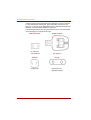
Front with the display closed . . . . . . . . . . . . . . . . . . . . . . . . . . . . . . .
Left side . . . . . . . . . . . . . . . . . . . . . . . . . . . . . . . . . . . . . . . . . . . . . . . . .
Right side . . . . . . . . . . . . . . . . . . . . . . . . . . . . . . . . . . . . . . . . . . . . . . .
Backside . . . . . . . . . . . . . . . . . . . . . . . . . . . . . . . . . . . . . . . . . . . . . . . .
Underside . . . . . . . . . . . . . . . . . . . . . . . . . . . . . . . . . . . . . . . . . . . . . . .
Front with the display open . . . . . . . . . . . . . . . . . . . . . . . . . . . . . . . . .
Fixed optical media drives. . . . . . . . . . . . . . . . . . . . . . . . . . . . . . . . . .
Region codes for DVD drive and media . . . . . . . . . . . . . . . . . . . . . .
Writable discs . . . . . . . . . . . . . . . . . . . . . . . . . . . . . . . . . . . . . . . . . .
CDs . . . . . . . . . . . . . . . . . . . . . . . . . . . . . . . . . . . . . . . . . . . . . . . . . .
User’s Manual
2-1
2-2
2-4
2-4
2-5
2-6
2-7
2-7
2-8
2-8
xxv
Table of Contents
Formats. . . . . . . . . . . . . . . . . . . . . . . . . . . . . . . . . . . . . . . . . . . . . . . .2-8
CD-ROM Drive . . . . . . . . . . . . . . . . . . . . . . . . . . . . . . . . . . . . . . . . . .2-8
DVD-ROM & CD-R/RW drive . . . . . . . . . . . . . . . . . . . . . . . . . . . . . . .2-9
AC adaptor . . . . . . . . . . . . . . . . . . . . . . . . . . . . . . . . . . . . . . . . . . . . . . .2-9
Chapter 3
Getting Started
Setting up your work space . . . . . . . . . . . . . . . . . . . . . . . . . . . . . . . . .3-2
General conditions . . . . . . . . . . . . . . . . . . . . . . . . . . . . . . . . . . . . . . .3-2
Placement of the computer. . . . . . . . . . . . . . . . . . . . . . . . . . . . . . . . .3-3
Seating and posture . . . . . . . . . . . . . . . . . . . . . . . . . . . . . . . . . . . . . .3-3
Lighting . . . . . . . . . . . . . . . . . . . . . . . . . . . . . . . . . . . . . . . . . . . . . . . .3-4
Work habits. . . . . . . . . . . . . . . . . . . . . . . . . . . . . . . . . . . . . . . . . . . . .3-4
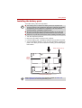
Installing the battery pack . . . . . . . . . . . . . . . . . . . . . . . . . . . . . . . . . . .3-5
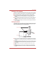
Connecting the AC adaptor. . . . . . . . . . . . . . . . . . . . . . . . . . . . . . . . . .3-6
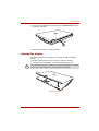
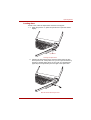
Opening the display . . . . . . . . . . . . . . . . . . . . . . . . . . . . . . . . . . . . . . . .3-7
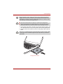
Turning on the power. . . . . . . . . . . . . . . . . . . . . . . . . . . . . . . . . . . . . . .3-8
Windows® XP setup . . . . . . . . . . . . . . . . . . . . . . . . . . . . . . . . . . . . . . . .3-8
Turning off the power. . . . . . . . . . . . . . . . . . . . . . . . . . . . . . . . . . . . . . .3-9
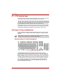
Shut Down mode (Boot mode) . . . . . . . . . . . . . . . . . . . . . . . . . . . . . .3-9
Hibernation Mode . . . . . . . . . . . . . . . . . . . . . . . . . . . . . . . . . . . . . . . .3-9
Standby Mode. . . . . . . . . . . . . . . . . . . . . . . . . . . . . . . . . . . . . . . . . . 3-11
Restarting the computer . . . . . . . . . . . . . . . . . . . . . . . . . . . . . . . . . . .3-12
Create Optical Recovery Discs (Depends on the model you
purchased.) . . . . . . . . . . . . . . . . . . . . . . . . . . . . . . . . . . . . . . . . . . . . . .3-13
Restoring the preinstalled software from the Recovery HDD
(Depends on the model you purchased.). . . . . . . . . . . . . . . . . . . . . .3-13
Restoring the preinstalled software from Recovery Media . . . . . . .3-14
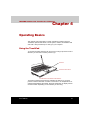
Chapter 4
Operating Basics
Using the TouchPad. . . . . . . . . . . . . . . . . . . . . . . . . . . . . . . . . . . . . . . .4-1
Using the optical media drive . . . . . . . . . . . . . . . . . . . . . . . . . . . . . . . .4-2
Loading discs . . . . . . . . . . . . . . . . . . . . . . . . . . . . . . . . . . . . . . . . . . .4-3
Removing discs . . . . . . . . . . . . . . . . . . . . . . . . . . . . . . . . . . . . . . . . .4-6
Writing CDs with the DVD-ROM & CD-R/RW drive . . . . . . . . . . . . . . .4-7
Important message (DVD-ROM & CD-R/RW drive) . . . . . . . . . . . . . .4-7
Before writing or rewriting. . . . . . . . . . . . . . . . . . . . . . . . . . . . . . . . . .4-7
When writing or rewriting . . . . . . . . . . . . . . . . . . . . . . . . . . . . . . . . . .4-8
Disclaimer (DVD-ROM & CD-R/RW drive) . . . . . . . . . . . . . . . . . . . . .4-8
TOSHIBA Direct Disc Writer . . . . . . . . . . . . . . . . . . . . . . . . . . . . . . . . .4-9
Media care. . . . . . . . . . . . . . . . . . . . . . . . . . . . . . . . . . . . . . . . . . . . . . . .4-9
CD/DVDs . . . . . . . . . . . . . . . . . . . . . . . . . . . . . . . . . . . . . . . . . . . . . .4-9
Sound System . . . . . . . . . . . . . . . . . . . . . . . . . . . . . . . . . . . . . . . . . . .4-10
Volume control . . . . . . . . . . . . . . . . . . . . . . . . . . . . . . . . . . . . . . . . .4-10
Microphone level . . . . . . . . . . . . . . . . . . . . . . . . . . . . . . . . . . . . . . .4-10
xxvi
User’s Manual
Table of Contents
Modem . . . . . . . . . . . . . . . . . . . . . . . . . . . . . . . . . . . . . . . . . . . . . . . . . 4-11
Region selection . . . . . . . . . . . . . . . . . . . . . . . . . . . . . . . . . . . . . . . .4-11
Properties menu . . . . . . . . . . . . . . . . . . . . . . . . . . . . . . . . . . . . . . . 4-12
Settings . . . . . . . . . . . . . . . . . . . . . . . . . . . . . . . . . . . . . . . . . . . . . . 4-12
Modem Selection . . . . . . . . . . . . . . . . . . . . . . . . . . . . . . . . . . . . . . 4-12
Dialing Properties . . . . . . . . . . . . . . . . . . . . . . . . . . . . . . . . . . . . . . 4-12
Connecting . . . . . . . . . . . . . . . . . . . . . . . . . . . . . . . . . . . . . . . . . . . 4-13
Disconnecting . . . . . . . . . . . . . . . . . . . . . . . . . . . . . . . . . . . . . . . . . 4-14
Wireless LAN . . . . . . . . . . . . . . . . . . . . . . . . . . . . . . . . . . . . . . . . . . . 4-14
Security . . . . . . . . . . . . . . . . . . . . . . . . . . . . . . . . . . . . . . . . . . . . . . 4-14
Wireless communication switch . . . . . . . . . . . . . . . . . . . . . . . . . . . 4-14
Wireless communication indicator . . . . . . . . . . . . . . . . . . . . . . . . . 4-15
LAN . . . . . . . . . . . . . . . . . . . . . . . . . . . . . . . . . . . . . . . . . . . . . . . . . . . 4-15
LAN cable types . . . . . . . . . . . . . . . . . . . . . . . . . . . . . . . . . . . . . . . 4-15
Connecting LAN cable . . . . . . . . . . . . . . . . . . . . . . . . . . . . . . . . . . 4-16
Disconnecting LAN cable . . . . . . . . . . . . . . . . . . . . . . . . . . . . . . . . 4-16
Cleaning the computer. . . . . . . . . . . . . . . . . . . . . . . . . . . . . . . . . . . . 4-16
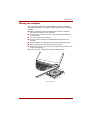
Moving the computer . . . . . . . . . . . . . . . . . . . . . . . . . . . . . . . . . . . . . 4-17
Chapter 5
The Keyboard
Typewriter keys. . . . . . . . . . . . . . . . . . . . . . . . . . . . . . . . . . . . . . . . . . .
F1 ... F12 function keys . . . . . . . . . . . . . . . . . . . . . . . . . . . . . . . . . . . .
Soft keys: Fn key combinations . . . . . . . . . . . . . . . . . . . . . . . . . . . . .
Emulating keys on enhanced keyboard . . . . . . . . . . . . . . . . . . . . . .
Hot keys. . . . . . . . . . . . . . . . . . . . . . . . . . . . . . . . . . . . . . . . . . . . . . . . .
Fn Sticky key (Depends on the model you purchased). . . . . . . . . . .
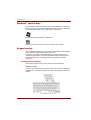
Windows® special keys . . . . . . . . . . . . . . . . . . . . . . . . . . . . . . . . . . . .
Keypad overlay . . . . . . . . . . . . . . . . . . . . . . . . . . . . . . . . . . . . . . . . . . .
Turning on the overlays. . . . . . . . . . . . . . . . . . . . . . . . . . . . . . . . . . .
Temporarily using normal keyboard (overlay on) . . . . . . . . . . . . . . .
Generating ASCII characters. . . . . . . . . . . . . . . . . . . . . . . . . . . . . . . .
Chapter 6
Power and Power-Up Modes
Power conditions . . . . . . . . . . . . . . . . . . . . . . . . . . . . . . . . . . . . . . . . .
Power indicators. . . . . . . . . . . . . . . . . . . . . . . . . . . . . . . . . . . . . . . . . .
Battery indicator . . . . . . . . . . . . . . . . . . . . . . . . . . . . . . . . . . . . . . . .
Power indicator . . . . . . . . . . . . . . . . . . . . . . . . . . . . . . . . . . . . . . . . .
Battery types. . . . . . . . . . . . . . . . . . . . . . . . . . . . . . . . . . . . . . . . . . . . .
Battery pack . . . . . . . . . . . . . . . . . . . . . . . . . . . . . . . . . . . . . . . . . . .
Real Time Clock battery . . . . . . . . . . . . . . . . . . . . . . . . . . . . . . . . . .
Care and use of the battery pack . . . . . . . . . . . . . . . . . . . . . . . . . . . .
Safety precautions . . . . . . . . . . . . . . . . . . . . . . . . . . . . . . . . . . . . . .
Charging the batteries. . . . . . . . . . . . . . . . . . . . . . . . . . . . . . . . . . . .
Monitoring battery capacity . . . . . . . . . . . . . . . . . . . . . . . . . . . . . . . .
User’s Manual
5-1
5-2
5-2
5-2
5-3
5-5
5-6
5-6
5-6
5-7
5-7
6-1
6-2
6-2
6-2
6-3
6-3
6-4
6-5
6-5
6-7
6-9
xxvii
Table of Contents
Maximizing battery operating time . . . . . . . . . . . . . . . . . . . . . . . . . . .6-9
Retaining data with power off . . . . . . . . . . . . . . . . . . . . . . . . . . . . . .6-10
Extending battery life . . . . . . . . . . . . . . . . . . . . . . . . . . . . . . . . . . . .6-10
Replacing the battery pack . . . . . . . . . . . . . . . . . . . . . . . . . . . . . . . . .6-11
Removing the battery pack . . . . . . . . . . . . . . . . . . . . . . . . . . . . . . . . 6-11
Installing the battery pack . . . . . . . . . . . . . . . . . . . . . . . . . . . . . . . . .6-12
Starting the computer by password . . . . . . . . . . . . . . . . . . . . . . . . . .6-12
Power-up modes . . . . . . . . . . . . . . . . . . . . . . . . . . . . . . . . . . . . . . . . .6-13
Hot keys . . . . . . . . . . . . . . . . . . . . . . . . . . . . . . . . . . . . . . . . . . . . . .6-13
Panel power off/on . . . . . . . . . . . . . . . . . . . . . . . . . . . . . . . . . . . . . . . .6-13
System Auto Off . . . . . . . . . . . . . . . . . . . . . . . . . . . . . . . . . . . . . . . . . .6-13
Chapter 7
HW Setup (Depends on the model you purchased)
Accessing HW Setup . . . . . . . . . . . . . . . . . . . . . . . . . . . . . . . . . . . . . . .7-1
HW Setup Window . . . . . . . . . . . . . . . . . . . . . . . . . . . . . . . . . . . . . . . . .7-1
Chapter 8
Optional Devices
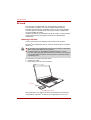
PC card . . . . . . . . . . . . . . . . . . . . . . . . . . . . . . . . . . . . . . . . . . . . . . . . . .8-2
Inserting a PC Card . . . . . . . . . . . . . . . . . . . . . . . . . . . . . . . . . . . . . .8-2
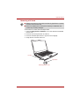
Removing a PC Card . . . . . . . . . . . . . . . . . . . . . . . . . . . . . . . . . . . . .8-3
Memory expansion. . . . . . . . . . . . . . . . . . . . . . . . . . . . . . . . . . . . . . . . .8-4
Installing a memory module . . . . . . . . . . . . . . . . . . . . . . . . . . . . . . . .8-5
Removing a memory module . . . . . . . . . . . . . . . . . . . . . . . . . . . . . . .8-6
Additional battery pack . . . . . . . . . . . . . . . . . . . . . . . . . . . . . . . . . . . . .8-7
Additional AC adaptor . . . . . . . . . . . . . . . . . . . . . . . . . . . . . . . . . . . . . .8-8
External monitor. . . . . . . . . . . . . . . . . . . . . . . . . . . . . . . . . . . . . . . . . . .8-8
Security lock . . . . . . . . . . . . . . . . . . . . . . . . . . . . . . . . . . . . . . . . . . . . . .8-9
Chapter 9
Troubleshooting
Problem solving process. . . . . . . . . . . . . . . . . . . . . . . . . . . . . . . . . . . .9-1
Preliminary checklist . . . . . . . . . . . . . . . . . . . . . . . . . . . . . . . . . . . . . .9-2
Analyzing the problem . . . . . . . . . . . . . . . . . . . . . . . . . . . . . . . . . . . .9-2
Hardware and system checklist . . . . . . . . . . . . . . . . . . . . . . . . . . . . . .9-3
System start-up. . . . . . . . . . . . . . . . . . . . . . . . . . . . . . . . . . . . . . . . . .9-3
Self test. . . . . . . . . . . . . . . . . . . . . . . . . . . . . . . . . . . . . . . . . . . . . . . .9-4
Power . . . . . . . . . . . . . . . . . . . . . . . . . . . . . . . . . . . . . . . . . . . . . . . . .9-4
Real Time Clock . . . . . . . . . . . . . . . . . . . . . . . . . . . . . . . . . . . . . . . . .9-6
Keyboard . . . . . . . . . . . . . . . . . . . . . . . . . . . . . . . . . . . . . . . . . . . . . .9-7
LCD panel. . . . . . . . . . . . . . . . . . . . . . . . . . . . . . . . . . . . . . . . . . . . . .9-7
Hard disk drive . . . . . . . . . . . . . . . . . . . . . . . . . . . . . . . . . . . . . . . . . .9-7
CD-RW & DVD-ROM drive . . . . . . . . . . . . . . . . . . . . . . . . . . . . . . . . .9-8
PC Card . . . . . . . . . . . . . . . . . . . . . . . . . . . . . . . . . . . . . . . . . . . . . . .9-9
Pointing device . . . . . . . . . . . . . . . . . . . . . . . . . . . . . . . . . . . . . . . . .9-10
USB . . . . . . . . . . . . . . . . . . . . . . . . . . . . . . . . . . . . . . . . . . . . . . . . .9-12
Memory expansion . . . . . . . . . . . . . . . . . . . . . . . . . . . . . . . . . . . . . .9-12
xxviii
User’s Manual
Table of Contents
Sound system . . . . . . . . . . . . . . . . . . . . . . . . . . . . . . . . . . . . . . . . .
Monitor . . . . . . . . . . . . . . . . . . . . . . . . . . . . . . . . . . . . . . . . . . . . . .
Modem . . . . . . . . . . . . . . . . . . . . . . . . . . . . . . . . . . . . . . . . . . . . . .
LAN . . . . . . . . . . . . . . . . . . . . . . . . . . . . . . . . . . . . . . . . . . . . . . . . .
Wireless LAN . . . . . . . . . . . . . . . . . . . . . . . . . . . . . . . . . . . . . . . . .
TOSHIBA support . . . . . . . . . . . . . . . . . . . . . . . . . . . . . . . . . . . . . . . .
Before you call . . . . . . . . . . . . . . . . . . . . . . . . . . . . . . . . . . . . . . . .
Where to write. . . . . . . . . . . . . . . . . . . . . . . . . . . . . . . . . . . . . . . . .
Appendix A
Specifications
Appendix B
Display Controller and Modes
Appendix C
Wireless LAN
Appendix D
AC Power Cord and Connectors
9-13
9-13
9-13
9-14
9-14
9-15
9-15
9-15
Glossary
Index
User’s Manual
xxix
Table of Contents
xxx
User’s Manual
TOSHIBA Satellite L30/ Satellite Pro L30Series
Preface
Congratulations on your purchase of the TOSHIBA Satellite L30 / Satellite
Pro L30 Series computer. This powerful notebook computer provides
excellent expansion capability, including multimedia devices, and it is
designed to provide years of reliable, high-performance computing.
This manual tells how to set up and begin using your TOSHIBA Satellite
L30 / Satellite Pro L30 Series computer. It also provides detailed
information on configuring your computer, basic operations and care, using
optional devices and troubleshooting.
If you are a new user of computers or if you’re new to portable computing,
first read over the Introduction and The Grand Tour chapters to familiarize
yourself with the computer's features, components and accessory devices.
Then read Getting Started for step-by-step instructions on setting up your
computer.
If you are an experienced computer user, please continue reading the
preface to learn how this manual is organized, then become acquainted
with this manual by browsing through its pages. Be sure to look over the
Specifications section of the Introduction, to learn about features that are
uncommon or unique to the computer. If you are going to install PC Cards
or connect external devices such as a monitor, be sure to read Chapter 8,
Optional Devices.
Manual contents
This manual is composed of the following nine chapters, four appendixes, a
glossary and an index.
Chapter 1, Introduction, is an overview of the computer's features,
capabilities, and options.
Chapter 2, The Grand Tour, identifies the components of the computer and
briefly explains how they function.
Chapter 3, Getting Started, provides a quick overview of how to begin
operating your computer and gives tips on safety and designing your work
area.
User’s Manual
xxxi
Preface
Chapter 4, Operating Basics, includes instructions on using the following
devices: TouchPad, Sound System, optical media drives, modem, wireless
communication and LAN. It also provides tips on care of the computer, and
CD/DVDs.
Chapter 5, The Keyboard, describes special keyboard functions including
the keypad overlay and hot keys.
Chapter 6, Power and Power-Up Modes, gives details on the computer's
power resources and battery save modes.
Chapter 7, HW Setup (Depends on the model you purchased.) explains
how to configure the computer using the HW Setup program.
Chapter 8, Optional Devices, describes the optional hardware available.
Chapter 9, Troubleshooting, provides helpful information on how to perform
some diagnostic tests, and suggests courses of action if the computer
doesn’t seem to be working properly.
The Appendices provide technical information about your computer.
The Glossary defines general computer terminology and includes a list of
acronyms used in the text.
The Index quickly directs you to the information contained in this manual.
Conventions
This manual uses the following formats to describe, identify, and highlight
terms and operating procedures.
Abbreviations
On first appearance, and whenever necessary for clarity, abbreviations are
enclosed in parentheses following their definition. For example: Read Only
Memory (ROM). Acronyms are also defined in the Glossary.
Icons
Icons identify ports, dials, and other parts of your computer. The indicator
panel also uses icons to identify the components it is providing information
on.
Keys
The keyboard keys are used in the text to describe many computer
operations. A distinctive typeface identifies the key top symbols as they
appear on the keyboard. For example, Enter identifies the Enter key.
xxxii
User’s Manual
Preface
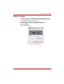
Key operation
Some operations require you to simultaneously use two or more keys. We
identify such operations by the key top symbols separated by a plus sign
(+). For example, Ctrl + C means you must hold down Ctrl and at the same
time press C. If three keys are used, hold down the first two and at the
same time press the third.
ABC
When procedures require an action such as
clicking an icon or entering text, the icon’s name
or the text you are to type in is represented in the
type face you see to the left.
ABC
Names of windows or icons or text generated by
the computer that appears on its display screen
is presented in the type face you see to the left.
Display
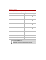
Messages
Messages are used in this manual to bring important information to your
attention. Each type of message is identified as shown below.
Pay attention! A caution informs you that improper use of equipment or
failure to follow instructions may cause data loss or damage your
equipment.
Please read. A note is a hint or advice that helps you make best use of
your equipment.
Indicates a potentially hazardous situation, which could result in death or
serious injury, if you do not follow instructions.
User’s Manual
xxxiii
Preface
xxxiv
User’s Manual
TOSHIBA Satellite L30 / Satellite Pro L30 Series
Chapter 1
Introduction
This chapter provides an equipment checklist, and it identifies the
computer's features, options and accessories.
Some of the features described in this manual may not function properly if
you use an operating system that was not pre-installed by TOSHIBA.
Equipment checklist
Carefully unpack your computer. Save the box and packing materials for
future use.
Hardware
Check to make sure you have all the following items:
■ TOSHIBA Satellite L30 / Satellite Pro L30 Series Portable Personal
Computer
■ Universal AC adaptor and power cord
■ Modular cable for modem (optional part dependant on model
purchased)
It is necessary to install the battery to use this computer. Refer to Installing
the battery pack section in Chapter 3, Getting Started.
User’s Manual
1-1
Introduction
Software
Windows® XP Home Edition / Professional / Starter Edition
The following software is preinstalled:
■ Microsoft® Windows® Home Edition / Professional / Starter Edition
■ Modem driver
■ Display driver for Windows®
■ TOSHIBA Utilities*
■ Wireless LAN driver (Can be used only with Wireless LAN models)
■ Sound driver for Windows®
■ DVD Video Player*
■ LAN driver
■ Pointing device driver
■ TOSHIBA Hotkey Utility
■ TOSHIBA User's Manual
■ TOSHIBA Assist*
■ TOSHIBA ConfigFree*
■ TOSHIBA Touch and Launch*
■ TOSHIBA Power Saver Utility*
■ TOSHIBA TouchPad On/Off Utility
■ TOSHIBA PC Diagnostic Tool*
■ TOSHIBA Zooming Utility*
Other software may preinstalled dependant on the model purchased.
* indicates an optional software / part that is dependant on the model
purchased.
If any of the items are missing or damaged, contact your dealer
immediately.
1-2
User’s Manual
Introduction
Features
Processor
Built-in
Intel® Celeron® M processor 360J or higher
Chipset
ATI® Radeon® Xpress 200M
Memory
Main Memory
Disclaimer
Part of the main system memory may be used by
the graphics system for graphics performance
and therefore reduce the amount of main system
memory available for other computing activities.
The amount of main system memory allocated to
support graphics may vary depending on the
graphics system, applications utilized, system
memory size and other factors. For PC's
configured with 4 GB of system memory, the full
system memory space for computing activities
will be considerably less and will vary by model
and system configuration.
Slots
Up to two 1024 MB memory modules can be
installed in the memory slot for a maximum of 2
GB system memory total.
Video RAM
Maximum 256 MB of RAM is provided for video
display. (1GB or more of system memory is
required.)
Power
User’s Manual
Battery Pack
Your computer is powered by a rechargeable
lithium-ion battery pack.
RTC Battery
The internal RTC battery backs up the Real Time
Clock and calendar.
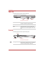
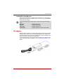
AC Adaptor
The universal AC adaptor provides power to the
system and recharges the batteries when they
are low. It comes with a detachable power cord.
Because it is universal, it can receive a range of
AC voltage from 100 to 240 volts; however, the
output current varies among different models.
Using the wrong model can damage your
computer. Refer to the AC adaptor section in
Chapter 2, The Grand Tour.
1-3
Introduction
Disks
Hard disk Disclaimer
1 Gigabyte (GB) means 109 = 1,000,000,000
bytes using powers of 10. The computer
operating system, however, reports storage
capacity using powers of 2 for the definition of 1
GB = 230 = 1,073,741,824 bytes, and therefore
shows less storage capacity. Available storage
capacity will also be less if the product includes
one or more pre-installed operating systems,
such as Microsoft Operating System and/or preinstalled software applications, or media content.
Actual formatted capacity may vary.
Hard disk Drive
Available in three sizes.
■ 40.0 billion bytes (37.26 GB)
■ 60.0 billion bytes (55.89 GB)
■ 80.0 billion bytes (74.53 GB)
Other hard disk drives may introduced in the
future.
Computers in this series can be configured with a fixed optical media drive.
The available optical media drives are described below.
DVD-ROM & CD-R/
RW Drive
1-4
Some models are equipped with a full-size,
DVD-ROM & CD-R/RW drive module that lets
you run CD/DVD's without using an adaptor. It
reads DVD-ROM's at maximum 8 speed and
CD-ROM's at maximum 24 speed. It writes
CD-R's at up to 24 speed and CD-RW's at up to
24 speed. This drive supports the following
formats:
■ CD-R
■ CD-RW
■ DVD-ROM
■ DVD-Video
■ CD-DA
■ CD-Text
■ Photo CD™ (Single/multi-session)
■ CD-ROM Mode 1, Mode 2
■ CD -ROM XA Mode 2 (Form1, Form 2)
■ Enhanced CD (CD-EXTRA)
User’s Manual
Introduction
CD-ROM Drive
Some models are supplied with a full size CDROM drive, that lets you play CD-ROMs without
using an adaptor. CD-ROMs are read at a
maximum speed of 24x. The drive supports the
following formats:
■ CD-Text
■ CD-Audio
■ CD-i
■ Video CD
■ Photo CD™ (Single/Multi Session)
■ CD ROM Mode 1, Mode 2
■ CD-ROM XA Mode 2 (Form 1, Form 2)
■ Enhanced CD (CD-Extra)
Display
The computer's LCD panel supports high-resolution video graphics. The
screen can be set at a wide range of viewing angles for maximum comfort
and readability.
Built-In
14.1” WXGA / or 15.4” WXGA TFT, non-glare, 16
M colors, with the following resolution:
1280 horizontal × 800 vertical pixels
Graphics Controller
Graphics controller maximizes display
performance. Refer to Display Controller and
Modes section in Appendix B, Display Controller
and Modes for more information.
Keyboard
Built-In
84 keys or 85 keys, compatible with IBM
enhanced keyboard, embedded numeric overlay,
dedicated cursor control,
and
keys.
Refer to Chapter 5, The Keyboard, for details.
Pointing Device
Built-In TouchPad
User’s Manual
A TouchPad and control buttons in the palm rest
enable control of the on-screen pointer and
scrolling of windows.
1-5
Introduction
Ports
External Monitor
Depending on the model you purchased:
15-pin, analog VGA port supports VESA DDC2B
compatible functions.
Universal Serial Bus
(USB 2.0)
The computer has Universal Serial Bus ports that
comply with the USB 2.0 standard, which
enables data transfer speeds 40 times faster
than the USB 1.1 standard. (The ports also
support USB 1.1.)
Slots
PC Card
Depending on the model you purchased:
The PC Card slot accommodates Type II card.
Multimedia
Sound System
A Windows® Sound System compatible sound
system provides speakers as well as jacks for an
external microphone and headphones.
Headphone Jack
This jack outputs analog audio signals.
Microphone Jack
A 3.5 mm mini microphone jack enables
connection of a three-conductor mini jack for
monaural microphone input.
Communications
1-6
Modem
The internal modem feature is not available on all
models. Where presents, it provides capability for
data and fax communication. It supports V.90
(V.92). The speed of data transfer and fax
communication depends on the analog
telephone line conditions. The computer has a
modem jack for connection to a telephone line.
Both of V.90 and V.92 are supported only in USA,
Canada, Australia, UK, France and Germany.
Only V.90 is available in other regions.
LAN
The computer has built-in support for Ethernet
LAN (10 megabits per second, 10BASE-T) and
Fast Ethernet LAN (100 megabits per second,
100BASE-TX).
User’s Manual
Introduction
Wireless LAN
The Wireless LAN feature is not available on all
models. Where present, it supports the B and G
standard but it is compatible with other LAN
systems based on Direct Sequence Spread
Spectrum / Orthogonal Frequency Division
Multiplexing radio technology that complies with
the IEEE 802.11 Standard.
■ Automatic Transmit Rate Select mechanism
in the transmit range of 54, 48, 36, 24, 18, 12,
9 and 6 Mbit/s. (IEEE 802.11g)
■ Automatic Transmit Rate Select mechanism in
the transmit range of 11, 5.5, 2 and 1 Mbit/s.
(IEEE 802.11b)
■ Roaming over multiple channels
■ Card Power Management
■ Wired Equivalent Privacy (WEP) data
encryption, based on 128 bit encryption
algorithm.
■ Advanced Encryption Standard (AES) data
encryption, based on 128 bit encryption
algorithm.
Software
User’s Manual
Operating System
Windows® XP Home Edition, Windows® XP
Professional, or Windows® XP Starter Edition
operating system and TOSHIBA Utilities and
drivers pre-installed on the hard disk. Refer to the
Software section at the front of this chapter.
TOSHIBA Utilities
A number of utilities and drivers are pre-installed
to make your computer more convenient to use.
Refer to the Utilities section in this chapter.
Plug and Play
When you connect an external device to the
computer or when you install a component, Plug
and Play capability enables the system to
recognize the connection and make the
necessary configurations automatically.
1-7
Introduction
Special features
The following features are either unique to TOSHIBA computers or are
advanced features, which make the computer more convenient to use.
Please note that the descriptions for starting some special features are
based on setting the Control Panel to Category View. On Classic view
the description is different.
1-8
Hot Keys
Key combinations let you quickly modify the
system configuration directly from the keyboard
without running a system configuration program.
Keypad Overlay
A ten-key pad is integrated into the keyboard.
Refer to the Keypad overlay section in Chapter 5,
The Keyboard, for instructions on using the
keypad overlay.
Power On Password
(Depends on the
model you
purchased.)
Two levels of password security, supervisor and
user, are available to prevent unauthorized
access to your computer.
To register a supervisor password, double click
the TOSHIBA Assist on your desktop select the
SECURE tab and start the Supervisor
password utility.
To set a user password, select the SECURE tab
on TOSHIBA Assist, then start User password
utility. In the Password tab you can register a
user password.
Instant Security
The hot key function Fn + F1 blanks the screen
and disables the computer, providing data
security.
Display Automatic
Power Off
This feature automatically cuts off power to the
internal display when there is no keyboard input
for a specified time. Power is restored when any
key is pressed.
To specify the time, On Windows XP Home
Edition/Professional model:
Click Start, Control Panel, Performance and
Maintenance. TOSHIBA Power Saver. On the
Basic Setup tab, you can specify the time for
Monitor Power OFF.
On Windows XP Starter Edition model:
Click Start, Control Panel, Performance and
Maintenance, Power Options. On the Power
Schemes tab, you can specify the time for Turn
off monitor.
User’s Manual
Introduction
User’s Manual
HDD Automatic
Power Off
This feature automatically cuts off power to the
hard disc drive when it is not accessed for a
specified time. Power is restored when the hard
disc is accessed.
To specify the time, On Windows XP Home
Edition/Professional model:
Click Start, Control Panel, Performance and
Maintenance. TOSHIBA Power Saver. On the
Basic Setup tab, you can specify the time for
HDD Power OFF.
On Windows XP Starter Edition model:
Click Start, Control Panel, Performance and
Maintenance, Power Options. On the Power
Schemes tab, you can specify the time for Turn
off hard disks.
System Automatic
Standby/Hibernation
This feature automatically shuts down the system
into Standby Mode or Hibernation Mode when
there is no input or hardware access for a
specified time.
To specify the time, On Windows XP Home
Edition/Professional model:
Click Start, Control Panel, Performance and
Maintenance. TOSHIBA Power Saver. On the
Basic Setup tab, you can specify the time for
either System standby or System hibernation
settings.
On Windows XP Starter Edition model:
Click Start, Control Panel, Performance and
Maintenance, Power Options. On the Power
Schemes tab, you can specify the time for either
System standby or System hibernates.
Intelligent Power
Supply
A microprocessor in the computer's intelligent
power supply detects the battery’s charge and
calculates the remaining battery capacity. It also
protects electronic components from abnormal
conditions, such as voltage overload from an
AC adaptor.
To monitor remaining battery, On Windows XP
Home Edition/Professional model:
Check Battery remaining on TOSHIBA Power
Saver.
On Windows XP Starter Edition model:
Check Power Meter tab on Power Options.
1-9
Introduction
1-10
Battery Save Mode
This feature lets you save battery power.
To specify the power save mode, On Windows
XP Home Edition/Professional model:
Click Start, Control Panel, Performance and
Maintenance. TOSHIBA Power Saver. At
Profile:, you can specify the power save mode.
On Windows XP Starter Edition model:
Click Start, Control Panel, Performance and
Maintenance, Power Options. On the Power
Schemes tab, you can select the mode for
Power schemes.
Panel Power On/Off
This feature turns power to the computer off
when the display panel is closed and turns it back
on when the panel is opened.
To specify the setting, On Windows XP Home
Edition/Professional model:
Click Start, Control Panel, Performance and
Maintenance. TOSHIBA Power Saver. On the
Setup Action tab, you can specify the setting for
When I close the lid.
On Windows XP Starter Edition model:
Click Start, Control Panel, Performance and
Maintenance, Power Options. and Acvanced
tab.
Low Battery
Automatic
Hibernation
When battery power is exhausted to the point
that computer operation cannot be continued, the
system automatically enters Hibernation Mode
and shuts down.
To specify the setting, On Windows XP Home
Edition/Professional model:
Click Start, Control Panel, Performance and
Maintenance. TOSHIBA Power Saver. On the
Setup Action tab, you can specify the setting.
On Windows XP Starter Edition model:
Click Start, Control Panel, Performance and
Maintenance, Power Options. On the Alarms
tab, you can specify the setting.
User’s Manual
Introduction
Heat dispersal
(Depends on the
model you
purchased.)
User’s Manual
To protect from overheating, the CPU has an
internal temperature sensor. If the computer’s
internal temperature rises to a certain level, the
cooling fan is turned on or the processing speed
is lowered. Use the Fan item of the Basic Setup
tab in TOSHIBA Power Saver.
■ Maximum
Performance
Turns on fan first, then if
necessary lowers CPU
processing speed.
■ Performance
Uses a combination of
fan and lowering the
CPU processing speed.
■ Battery optimized
Lowers the CPU
processing speed first,
then if necessary turns
on the fan.
Hibernation
This feature lets you turn off the power without
exiting from your software. The contents of main
memory are saved to the hard disk so that when
you turn on the power again, you can continue
working right where you left off. Refer to the
Turning off the power section in Chapter 3,
Getting Started, for details.
Standby
If you have to interrupt your work, you can turn
off the power without exiting from your software.
Data is maintained in the computer's main
memory so that when you turn on the power
again, you can continue working right where you
left off.
1-11
Introduction
Utilities
This section describes pre-installed utilities and tells how to start them. For
details on operations, refer to each utility’s online manual, help files or
readme.txt files.
Please note that the descriptions for starting some Utilities are based on
setting the Control Panel to Category View. On Classic view the
description is different.
1-12
TOSHIBA Assist
(Depends on the
model you
purchased.)
TOSHIBA Assist is a graphical user interface that
provides easy access to help and services.
TOSHIBA Power
Saver (Depends on
the model you
purchased.)
To access this power saving and management
program, click the Control Panel, Performance
and Maintenance, and TOSHIBA Power Saver.
HW Setup (Depends
on the model you
purchased.)
This program lets you customize your hardware
settings according to the way you work with your
computer and the peripherals you use. To start
the utility, double click the TOSHIBA Assist on
your desktop, select OPTIMIZE tab , and click
TOSHIBA HW Settings.
DVD Video Player
(Depends on the
model you
purchased.)
The DVD Video Player is used to play DVD
Video. It has an on-screen interface and
functions. Click start, point to All Programs,
point to InterVideo WinDVD, then click
InterVideo WinDVD.
TOSHIBA Zooming
Utility (Depends on
the model you
purchased.)
This utility allows you to enlarge or reduce the
icon size on the desktop or the application
window.
To run TOSHIBA Zooming Utility, click start,
select All Programs followed by TOSHIBA
followed by Utilities and then click Zooming
Utility.
TOSHIBA Disc
Creator
You can create CD/DVD's in several formats
including audio CD's that can be played on a
standard stereo CD player and data CD's to store
the files and folders on your hard disk drive. This
software can be used on a model with the
DVD-ROM & CD-R/RW drive, and the DVD
Super Multi drive.
User’s Manual
Introduction
User’s Manual
TOSHIBA Direct Disc
Writer
TOSHIBA Direct Disc Writer is the packet writing
software which provides the function which writes
files and/or folders to DVD+RW, DVD-RW or
CD-RW disc via a drive letter like a floppy disk or
other removable disks.
TOSHIBA PC
Diagnostic Tool
(Depends on the
model you
purchased.)
TOSHIBA PC Diagnostic Tool displays the basic
information on the computer's configuration and
allows some of the built-in devices functionality to
be tested. To start the TOSHIBA PC Diagnostic
Tool, click start, point to All Programs, point to
TOSHIBA, and point to Utilities and click PC
Diagnostic Tool.
TOSHIBA ConfigFree
(Depends on the
model you
purchased.)
ConfigFree is a suite of utilities to allow easy
control of communication device and network
connections. ConfigFree also allows you to find
communication problems and create profiles for
easy switching between location and
communication networks.
To run ConfigFree, click start, select All
Programs followed by TOSHIBA followed by
Networking and then click ConfigFree.
TOSHIBA TouchPad
On/Off Utility
Pressing Fn + F9 enables or disables the
TouchPad function. When you press these hot
keys, the current setting will change and be
displayed as an icon.
TOSHIBA Touch and
Launch (Depends on
the model you
purchased.)
TOSHIBA Touch and Launch is a tool that allows
you to perform various tasks easily using the
TouchPad. TOSHIBA Touch and Launch is useful
in the following conditions.
■ To open a file located on the desktop whose
icon is obscured by a window.
■ To open a page contained in the Internet
Explorer Favorites menu.
■ To display the list of currently open windows
and change the active window.
Also TOSHIBA Touch and Launch provides the
following functions by customizing the settings.
■ To open a file stored in a pre-defined folder.
■ To quickly launch your frequently used
applications which have been registered.
To run TOSHIBA Touch and Launch, click start,
select All Programs followed by TOSHIBA
followed by Utilities and then click Touch and
Launch
1-13
Introduction
Options
You can add a number of options to make your computer even more
powerful and convenient to use. Refer to Chapter 8 Optional Devices, for
details. The following options are available:
Memory expansion
Two memory modules can be installed in this
computer.
Use only DDRII-533MHz compatible memory modules. See your
TOSHIBA dealer for details.
1-14
Battery pack
An additional battery pack can be purchased
from your TOSHIBA dealer. Use it as a spare or
replacement.
AC Adaptor
If you use your computer at more than one site
frequently, it may be convenient to purchase an
additional AC adaptor for each site so you will not
have to carry the adaptor with you.
User’s Manual
TOSHIBA Satellite L30/ Satellite Pro L30 Series
Chapter 2
The Grand Tour
This chapter identifies the various components of your computer. Become
familiar with each component before you operate the computer.
Front with the display closed
The following figure shows the computer's front with its display panel in the
closed position.
Power/Battery/
HDD LEDs
Speaker
Wireless Activity
LED
Wireless
Communication Switch
Display Latch
Headphone Microphone
Jack
Jack
Speaker
Front of the computer with display closed
User’s Manual
Speakers
The speakers emit sound generated by your
software as well as audio alarms, such as low
battery condition, generated by the system.
Power
The Power indicator glows green when the
computer is on. If you select Standby from Turn
Off Computer, this indicator flashes orange
(one second on, two seconds off) while the
computer enters Standby mode.
Battery
The Battery indicator shows the condition of the
battery's charge: Green indicates a full charge,
orange indicates that the battery is charging and
flashing orange indicates a low battery charge.
Refer to Chapter 6, Power and Power-Up Modes.
2-1
The Grand Tour
Built-in HDD/ODD
The Built-in HDD/ODD indicator glows green
when the computer accesses the hard disk drive
or and optical disc drive.
Wireless
Communication
Switch
The Wireless Communication Switch turns on the
wireless LAN. (Depends on the model you
purchased.)
Set the switch to off in airplanes and hospitals. Check the wireless activity
indicator. It will stop glowing when the wireless communication function is
off.
Wireless Activity
LED
Shows you Wireless LAN activity, and whether
the Wireless LAN feature is engaged or not.
Display Latch
This latch secures the LCD panel in its closed
position. Slide the latch to open the display.
Headphone Jack
This jack outputs analog audio signals.
Microphone Jack
A 3.5 mm mini microphone jack enables
connection of a three-conductor mini jack for
monaural microphone input.
Left side
The following figure shows the computer's left side.
External Monitor Port
USB Port
Cooling Vents
PC Card Slot
Modem Jack
The left side of the computer
2-2
User’s Manual
The Grand Tour
External Monitor
Port
This 15-pin port lets you connect an external
video display. The Analog VGA port supports
VESA DDC2B compatible functions. (Depends
on the model you purchased.)
Cooling Vents
Cooling vents help prevent the CPU from
overheating.
Do not block the cooling vents. Also ensure that foreign objects are kept
out of the vents as items such as pins or similar objects, which can
damage the computer's circuitry.
User’s Manual
Universal Serial Bus
(USB 2.0) ports
A Universal Serial Bus port is on the left side.
The port complies with the USB 2.0 standard,
which enables data transfer speeds 40 times
faster than the USB 1.1 standard (The ports also
support USB 1.1). Keep foreign objects out of the
USB connectors. A pin or similar object can
damage the computer's circuitry. Operation of all
functions of all USB devices has not been
confirmed. As such, some untested third-party
devices may not function properly.
Modem Jack
The modem jack allows you to use a modular
cable to connect the modem directly to a
telephone line. (Depends on the model you
purchased.)
■ In case of a lightning storm, unplug the
modem cable from the telephone jack.
■ Do not connect the modem to a digital
telephone line. A digital line will damage the
modem.
PC Card Slot
A PC Card slot can accommodate Type II cards.
The slot supports 16-bit PC Cards and CardBus
PC Cards. (Depends on the model you
purchased.)
2-3
The Grand Tour
Right side
The following figure shows the computer's right side.
ODD
Indicator
Eject Button
Emergency
Eject Hole
The right side of the computer
ODD Indicator
The ODD indicator glows amber when the
computer accesses the optical disc drive.
Eject Button
Press this button to open the ODD tray.
Emergency Eject
Hole
In the event that the disc drive becomes
inexplicably locked or stops responding press
this button to force a manual ejection of the ODD
tray.
Backside
The following figure shows the computer's back panel.
USB Port
Security Lock
DC IN 19V Jack
LAN Jack
The backside of the computer
Security Lock
2-4
A security cable attaches to this port. The
optional security cable anchors your computer to
a desk or other large object to deter theft.
User’s Manual
The Grand Tour
Universal Serial Bus
(USB 2.0) ports
A single of Universal Serial Bus port is on the
back side. The port complies with the USB 2.0
standard, which enables data transfer speeds 40
times faster than the USB 1.1 standard (The
ports also support USB 1.1). Keep foreign
objects out of the USB connectors. A pin or
similar object can damage the computer's
circuitry. Operation of all functions of all USB
devices has not been confirmed. As such, some
untested third-party devices may not function
properly.
DC IN 19V Jack
The AC adaptor connects to this socket. Use
only the model of AC adaptor that comes with the
computer. Using the wrong adaptor can damage
your computer.
LAN Jack
This jack lets you connect to a LAN. The adaptor
has built-in support for Ethernet LAN (10
megabits per second, 10BASE-T) and Fast
Ethernet LAN (100 megabits per second,
100BASE-TX). Refer to Chapter 4, Operating
Basics, for details.
Underside
The following figure shows the underside of the computer. Make sure the
display is closed before turning over your computer.
Battery Pack
Battery Release Latch (2)
Battery
Release
Lock (1)
Cooling
Vents
Memory
Module
Cover
HDD
Cover
Wireless
LAN
Cover
The underside of the computer
User’s Manual
2-5
The Grand Tour
Hard Disk Cover
This cover protects the hard disk.
Battery Release
Lock (1)
Slide this lock to prepare the battery pack for
removal.
Battery Pack
The battery pack powers the computer when the
AC adaptor is not connected. For detailed
information on the battery pack, refer to
Chapter 6, Power and Power-Up Modes.
Battery Release
Latch (2)
Slide and hold this latch to release the battery
pack for removal. For detailed information on
removing the battery packs, refer to Chapter 6,
Power and Power-Up Modes.
Cooling Vents
Cooling vents help prevent the CPU from
overheating.
Memory Module
Cover
This cover protects two memory module sockets -one or two modules are preinstalled. Refer to the
Memory expansion section in Chapter 8, Optional
Devices.
Wireless LAN Cover
This cover protects the Wireless LAN bay and, if
installed, the Wireless LAN card.
Front with the display open
This section shows the front of the computer with the display open. Refer to
the appropriate illustration for details. To open the display, slide the display
latch on the front of the display and lift up. Position the display at a
comfortable viewing angle.
Display Screen
Power Button
TouchPad
TouchPad Control
Buttons
The front of the computer with the display open
2-6
User’s Manual
The Grand Tour
Power Button
Turns the computer on and off as well as putting
it into Hibernation mode and waking it up from
Stand by mode.
Display Screen
The LCD displays high-contrast text and
graphics. Refer to Appendix B, Display Controller
and Modes. When the computer operates on the
AC adaptor the display screen’s image will be
somewhat brighter than when it operates on
battery power. The lower brightness level is
intended to save battery power.
TouchPad
A TouchPad located in the centre of the palm rest
is used to control the on-screen pointer.
TouchPad Control
Buttons
These let you select menu items or manipulate
text and graphics designated by the on-screen
pointer. Refer to the Using the TouchPad section
in Chapter 4, Operating Basics.
Fixed optical media drives
One of the following optical media drives is installed in the computer, either
a CD-ROM drive or DVD-ROM&CD-R/RW drive. An ATAPI interface
controller is used for CD/DVD operation. When the computer is accessing a
CD/DVD, an indicator on the drive glows.
Region codes for DVD drive and media
DVD-ROM&CD-R/RW drive and their associated media are manufactured
according to the specifications of six marketing regions. When you
purchase DVD-Video, make sure it matches your drive, otherwise it will not
play properly.
Code
User’s Manual
Region
1
Canada, United States
2
Japan, Europe, South Africa, Middle East
3
Southeast Asia, East Asia
4
Australia, New Zealand, Pacific Islands, Central
America, South America, Caribbean
5
Russia, Indian Subcontinent, Africa, North Korea,
Mongolia
6
China
2-7
The Grand Tour
Writable discs
This section describes the types of writable CD discs. Check the
specifications of your drive for the type of discs it can write. Use TOSHIBA
Disc Creator to write compact discs. Refer to Chapter 4, Operating Basics.
CDs
■ CD-R discs can be written only once. The recorded data cannot be
erased or changed.
■ CD-RW discs can be recorded more than once. Use either 1, 2, or 4
multi speed CD-RW discs or high-speed 4- to 10-speed discs. The write
speed of the ultra-speed CD-RW discs (Ultra-speed is available on the
DVD-ROM & CD-R/RW drive only) is a maximum of 24-speed.
Formats
The drives support the following formats:
■ DVD-ROM*
■ CD-DA
■ Photo CDTM (single/multi-session)
■ CD-ROM XA Mode 2 (Form1, Form2)
■ CD-R
■ DVD -Video*
■ CD-Text
■ CD-ROM Mode 1, Mode 2
■ Enhanced CD (CD-EXTRA)
■ CD-RW
* Not available on the CD-ROM drive.
CD-ROM Drive
The full size CD-ROM drive module lets you play either 12cm (4.72") or
8cm (3.15") CDs without using an adaptor:
The read speed is slower at the center of a disc and faster at the outer
edge.
CD read
24 speed (maximum)
2-8
User’s Manual
The Grand Tour
DVD-ROM & CD-R/RW drive
The full-size DVD-ROM & CD-R/RW drive module lets you record data to
writable CDs as well as run either 12 cm (4.72") or 8 cm (3.15") CD/DVDs
without using an adaptor.
The read speed is slower at the centre of a disc and faster at the outer
edge.
DVD read
8 speed (maximum)
CD read
24 speed (maximum)
CD-R write
24 speed (maximum)
CD-RW write
24 speed (maximum, Ultra speed media)
AC adaptor
The AC adaptor converts AC power to DC power and reduces the voltage
supplied to the computer. It can automatically adjust to any voltage from
100 to 240 volts and to a frequency of either 50 or 60 hertz, enabling you to
use the computer in almost any country/region.
To recharge the battery, simply connect the AC adaptor to a power source
and the computer. Refer to Chapter 6, Power and Power-Up Modes, for
details.
The AC adaptor
User’s Manual
2-9
The Grand Tour
■ Use only the AC adaptor that came with the computer or an equivalent
optional adaptor. Use of the wrong adaptor could damage your
computer. TOSHIBA assumes no liability for any damage in such case.
■ Use only the AC Adaptor supplied with your computer or an equivalent
adapter that is compatible. Use of any incompatible adaptor or other
types of AC Adaptors may have a different voltage which could cause
damage to your computer, computer failure and/or possible data loss.
Toshiba assumes no liability for any damage, computer failure and/or
data loss caused by use of an incompatible adaptor.
Use only the AC adaptor supplied as an accessory. Other AC adaptors
have different voltage and terminal polarities and use of them may produce
heat and smoke or even result in fire or rupture.
2-10
User’s Manual
TOSHIBA Satellite L30 / Satellite Pro L30 Series
Chapter 3
Getting Started
This chapter provides basic information to get you started using your
computer. It covers the following topics:
■ Setting up your work space - for your health and safety
Be sure also to read the Safety Instruction Manual. This guide, which is
included with the computer, explains product liability.
■
■
■
■
Installing the battery pack
Connecting the AC adaptor
Opening the display
Turning on the power
■
■
■
■
Windows® XP setup
Turning off the power
Restarting the computer
Restoring the preinstalled software
All users should be sure to read the section Windows® XP setup.
User’s Manual
3-1
Getting Started
Setting up your work space
Establishing a comfortable work site is important for you and your
computer. A poor work environment or stressful work habits can result in
discomfort or serious injury from repetitive strain to your hands, wrists or
other joints. Proper ambient conditions should also be maintained for the
computer's operation. This section discusses the following topics:
■ General conditions
■ Placement of the computer
■ Seating and posture
■ Lighting
■ Work habits
General conditions
In general, if you are comfortable, so is your computer, but read the
following to make sure your work site provides a proper environment.
■ Make sure there is adequate space around the computer for proper
ventilation.
■ Make sure the AC power cord connects to an outlet that is close to the
computer and easily accessible.
■ The temperature should be 5 to 35 degrees Centigrade (41 to
95 degrees Fahrenheit) and the relative humidity should be 20 to
80 percent.
■ Avoid areas where rapid or extreme changes in temperature or humidity
may occur.
■ Keep the computer free of dust, moisture, and exposure to direct
sunlight.
■ Keep the computer away from heat sources, such as electric heaters.
■ Do not use the computer near liquids or corrosive chemicals.
■ Do not place the computer near objects that create strong magnetic
fields (e.g., stereo speakers).
■ Some components in the computer, including data storage media, can
be damaged by magnets. Do not place the computer near magnetic
objects or bring magnetic objects close to the computer. Be careful of
objects, such as stereo speakers, that produce strong magnetic fields
during operation. Also, be careful with metal objects, such as bracelets,
which can be inadvertently magnetized.
■ Do not operate the computer in close proximity to a mobile phone.
■ Leave ample ventilation room for the fan. Do not block the vents.
3-2
User’s Manual
Getting Started
Placement of the computer
Position the computer and peripheral devices to provide comfort and safety.
■ Set the computer on a flat surface at a comfortable height and distance.
■ The display should be no higher than eye level to avoid eyestrain.
■ Place the computer so that it is directly in front of you when you work
and make sure you have adequate space to easily operate other
devices.
■ Allow adequate space behind the computer to let you freely adjust the
display. The display should be angled to reduce glare and maximize
visibility.
■ If you use a paper holder, set it at about the same height and distance
as the computer.
Seating and posture
The height of your chair in relation to the computer and keyboard as well as
the support it gives your body are primary factors in reducing work strain.
Refer to the following tips and to the following figure.
Below eye level
90°angles
Foot rest
Posture and positioning of the computer
■ Place your chair so that the keyboard is at or slightly below the level of
your elbow. You should be able to type comfortably with your shoulders
relaxed.
■ Your knees should be slightly higher than your hips. If necessary, use a
foot rest to raise the level of your knees to ease pressure on the back of
your thighs.
■ Adjust the back of your chair so it supports the lower curve of your
spine.
■ Sit straight so that your knees, hips and elbows form approximately
90 degree angles when you work. Do not slump forward or lean back
too far.
User’s Manual
3-3
Getting Started
Lighting
Proper lighting can improve legibility of the display and reduce eyestrain.
■ Position the computer so that sunlight or bright indoor lighting does not
reflect off the screen. Use tinted Windows, shades or other screen to
eliminate sun glare.
■ Avoid placing the computer in front of bright light that could shine
directly in your eyes.
■ If possible, use soft, indirect lighting in your computer work area. Use a
lamp to illuminate your documents or desk, but be sure to position the
lamp so that it does not reflect off the display or shine in your eyes.
Work habits
A key to avoiding discomfort or injury from repetitive strain is to vary your
activities. If possible, schedule a variety of tasks into your workday. If you
must spend long periods at the computer, finding ways to break up the
routine can reduce stress and improve your efficiency.
■ Sit in a relaxed posture. Good positioning of your chair and equipment
as described earlier can reduce tension in your shoulders or neck and
ease back strain.
■ Vary your posture frequently.
■ Occasionally stand up and stretch or exercise briefly.
■ Exercise and stretch your wrists and hands a number of times during
the day.
■ Frequently, look away from the computer and focus your eyes on a
distant object for several seconds, for example 30 seconds every
15 minutes.
■ Take frequent short breaks instead of one or two long breaks, for
example, two or three minutes every half hour.
■ Have your eyes examined regularly and visit a doctor promptly, if you
suspect you might be suffering from a repetitive strain injury.
A number of books are available on ergonomics and repetitive strain injury
or repetitive stress syndrome. For more information on these topics or for
pointers on exercises for such stress points as hands and wrists, please
check with your library or book vendor. Also refer to the computer's Safety
Instruction Manual.
3-4
User’s Manual
Getting Started
Installing the battery pack
To install a battery, follow the steps below.
■ The battery pack is a lithium ion battery, which can explode if not
properly replaced, used, handled or disposed of. Dispose of the battery
as required by local ordinances or regulations. Use only batteries
recommended by TOSHIBA as replacements.
■ Do not touch the latch while holding the computer. Or you may get
injured by the dropped battery by unintentional release of the latch.
■ Please do not push the power button before installing the battery pack.
1.
2.
3.
4.
Turn the computer's power off.
Disconnect all cables connected to the computer.
Insert the battery pack. The Battery Release Latch (2) clicks into place.
Secure the Battery Release Lock (1) to ensure the battery is locked into
place. Later, when you want to remove the battery you must disengage
this lock first.
Battery Release Latch (2)
Battery
Release
Lock (1)
Securing the battery pack
Refer to Removing the battery pack section in Chapter 6, Power and
Power-Up Modes, for removing the battery pack.
User’s Manual
3-5
Getting Started
Connecting the AC adaptor
Attach the AC adaptor when you need to charge the battery or you want to
operate from AC power. It is also the fastest way to get started, because
the battery pack will need to be charged before you can operate from
battery power.
The AC adaptor can be connected to any power source supplying from 100
to 240 volts and 50 or 60 hertz. For details on using the AC adaptor to
charge the battery pack, refer to Chapter 6, Power and Power-Up Modes.
Use only the AC adaptor supplied as an accessory. Other AC adaptors
have different voltage and terminal polarities and use of them may produce
heat and smoke or even result in fire or rupture.
■ Use only the AC adaptor supplied with your computer or an equivalent
adaptor that is compatible. Use of any incompatible adaptor could
damage your computer. TOSHIBA assumes no liability for any damage
caused by use of an incompatible adaptor.
■ When you connect the AC adaptor to the computer, always follow the
steps in the exact order as described in the User's Manual. Connecting
the power cable to a live electrical outlet should be the last step
otherwise the adaptor DC output plug could hold an electrical change
and cause an electrical shock or minor bodily injury when touched. As
a general safety precaution, avoid touching any metal parts.
1. Connect the power cord to the AC adaptor.
Connecting the power cord to the AC adaptor
3-6
User’s Manual
Getting Started
2. Connect the AC adaptor's DC output plug to the DC IN 19V jack on the
back of the computer.
Connecting the adaptor to the computer
3. Plug the power cord into a live wall outlet.
Opening the display
The display panel can be rotated in a wide range of angles for optimal
viewing.
1. Slide the display latch on the front of the computer to the right.
2. Lift the panel up and adjust it to the best viewing angle for you.
Use reasonable care when opening and closing the display panel. Opening
it vigorously or slamming it shut could damage the computer.
Opening the display
User’s Manual
3-7
Getting Started
Turning on the power
This section describes how to turn on the power.
After you turn on the power for the first time, do not turn it off until you have
set up the operating system. Refer to the section Windows® XP setup.
Press and hold the computer's power button for two or three seconds.
Turning on the power
Windows® XP setup
When you first turn on the power, the computer's initial screen is the
Microsoft® Windows® XP Startup Screen Logo.
Follow the on-screen directions.
Be sure to read the Windows End User License Agreement display
carefully.
3-8
User’s Manual
Getting Started
Turning off the power
The power can be turned off in one of the following modes: Shut down
(Boot), Hibernation or Standby Mode.
Shut Down mode (Boot mode)
When you turn off the power in Shut Down mode no data is saved and the
computer will boot to the operating system’s main screen.
1. If you have entered data, save it to the hard disk.
2. Make sure all disk (disc) activity has stopped, then remove the CD/
DVDs.
Make sure the Built-in HDD/ODD indicators are off. If you turn off the
power while a disk (disc) is being accessed, you can lose data or damage
the disk (disc).
3. Click start then click Turn Off Computer. From the Turn Off
Computer menu select Turn Off.
4. Turn off the power to any peripheral devices.
Do not turn the computer or devices back on immediately. Wait a moment
to let all capacitors fully discharge.
Hibernation Mode
The hibernation feature saves the contents of memory to the hard disk
when the computer is turned off. The next time the computer is turned on,
the previous state is restored. The hibernation feature does not save the
status of peripheral devices.
■ Save your data. While entering Hibernation Mode, the computer saves
the contents of memory to the HDD. However, for safety sake, it is best
to save your data manually.
■ Data will be lost if you remove the battery or disconnect the AC adaptor
before the save is completed. Wait for the disk indicator to go out.
■ Do not install or remove a memory module while the computer is in
Hibernation Mode. Data will be lost.
User’s Manual
3-9
Getting Started
Benefits of Hibernation Mode
The Hibernation Mode feature provides the following benefits:
■ Saves data to the hard disk when the computer automatically shuts
down because of a low battery.
For the computer to shut down in Hibernation Mode, the hibernation
feature must be enabled in two places in Power Options: Hibernate tab and
TOSHIBA Power Saver: Basic Setup tab.
Otherwise, the computer will shut down in Standby Mode. If battery power
becomes depleted, data saved in Standby Mode will be lost.
■ You can return to your previous working environment immediately when
you turn on the computer.
■ Saves power by shutting down the system when the computer receives
no input or hardware access for the duration set by the System
hibernate feature.
■ You can use the panel power off feature.
Starting Hibernation Mode
You can also enable Hibernation Mode by pressing Fn + F4. Refer to
Chapter 5, The Keyboard, for details.
To enter Hibernation Mode, follow the steps below.
1. Click start.
2. Select Turn Off Computer.
3. Open the Turn off Computer dialog box. If Hibernate is not displayed,
go to step 4. If Hibernate is displayed, go to step 5.
4. Press the Shift key. The Standby item will change to Hibernate.
5. Select Hibernate.
Automatic Hibernation Mode
The computer will enter Hibernation mode automatically when you press
the power button or close the Display Screen. First, however, make the
appropriate settings according to the steps below.
1. Open the Control Panel.
2. Open Performance and Maintenance and open Power Options.
3. Select the Hibernate tab in the Power Options Properties, select
the Enable hibernation check box and click the Apply button.
4. Click the OK button.
5. Open Toshiba Power Saver.
6. Select Setup Action tab.
7. Enable the desired Hibernation settings for When I press the power
button and When I close the lid of my portable computer.
8. Click the OK button.
3-10
User’s Manual
Getting Started
Data save in Hibernation Mode
When you turn off the power in Hibernation Mode, the computer takes a
moment to save current memory data to the hard disk. During this time, the
disk indicator will light.
After you turn off the computer and memory is saved to the hard disk, turn
off the power to any peripheral devices.
Do not turn the computer or devices back on immediately. Wait a moment
to let all capacitors fully discharge.
Standby Mode
If you have to interrupt your work, you can turn off the power without exiting
from your software. Data is maintained in the computer's main memory.
When you turn on the power again, you can continue working right where
you left off.
■ When the AC adaptor is connected, the computer will go into Standby
Mode according to the settings in the TOSHIBA Power Saver.
■ To restore operation from Standby Mode, press the power button or
press any key. The latter action works only if Wake-up on Keyboard is
enabled in HW Setup.
■ If the computer automatically enters Standby Mode while a network
application is active, the application might not be restored when the
computer wakes up from Standby.
■ To prevent the computer from automatically entering Standby Mode,
disable Standby in the TOSHIBA Power Saver. That action, however,
will nullify the computer's Energy Star compliance.
■ Before entering Standby Mode, be sure to save your data.
■ Do not install or remove a memory module while the computer is in
Standby Mode. The computer or the module could be damaged.
■ Do not remove the battery pack while the computer is in Standby Mode
(unless the computer is connected to an AC power source). Data in
memory will be lost.
■ If you carry the computer on board an aircraft or into a hospital, be sure
to shut down the computer in Hibernation Mode or in shutdown mode
to avoid radio signal interference.
Benefits of Standby Mode
The Standby Mode feature provides the following benefits:
■ Restores the previous working environment more rapidly than does
Hibernation Mode.
■ Saves power by shutting down the system when the computer receives
no input or hardware access for the duration set by the System Standby
feature.
■ You can use the panel power off feature.
User’s Manual
3-11
Getting Started
Entering Standby Mode
You can enter Standby Mode in one of three ways:
1. Click Start, click Turn Off Computer and click Stand by.
2. Close the display panel. This feature must be enabled. Refer to the
Setup Action tab in TOSHIBA Power Saver Utility.
3. Press the power button. This feature must be enabled. Refer to the
Setup Action tab in TOSHIBA Power Saver Utility.
When you turn the power back on, you can continue where you left when
you shut down the computer.
You can also enable Standby by pressing Fn + F3. Refer to Chapter 5, The
Keyboard, for details.
■ When the computer is shut down in Standby Mode, the power indicator
flashes orange.
■ If you are operating the computer on battery power, you can lengthen
the operating time by shutting down in Hibernation Mode, as Standby
Mode consumes more power.
Standby Mode limitations
Standby Mode will not function under the following conditions:
■ Power is turned back on immediately after shutting down.
■ Memory circuits are exposed to static electricity or electrical noise.
Restarting the computer
Certain conditions require that you reset the system. For example, if:
■ You change certain computer settings.
■ An error occurs and the computer does not respond to your keyboard
commands.
■ There are three ways to reset the computer system:
1. Click start then click Turn off computer. From the Turn off
computer menu select Restart.
2. Press Ctrl + Alt + Del to display the Windows® Task Manager, then
select Shutdown and Restart.
3. Press the power button and hold it down for five seconds. Wait 10 to
15 seconds, then turn the power on again by pressing the power button.
3-12
User’s Manual
Getting Started
Create Optical Recovery Discs (Depends on the
model you purchased.)
A recovery image of your computer is stored on the hard disk. You may use
this image to create CD or DVD recovery discs using the following steps:
1. Select either blank CDs or DVD media.
2. The application will allow you to choose a type of media to create
recovery CDs/DVD including: CD-R, CD-RW, DVD-R, DVD-RW,
DVD+R and DVD+RW.
Some media may not be compatible with the Optical Drive of your
computer. Please verify your Optical Drive supports the blank media you
choose.
3.
4.
5.
6.
Turn on your computer to open Windows XP.
Insert the (first) blank media into the tray of the Optical Drive.
Click Start, All Programs, and Recovery Disc Creator.
After TOSHIBA Recovery Disc Creator starts, select the type of media
and the title you wish to copy to the media then click the Create button.
If your Optical Drive can only write to CDs, select "CD" as the "Disc Set" on
TOSHIBA Recovery Disc Creator If your Optical Drive of your computer
can write to either CD or DVDs, select the one you are using as the "Disc
Set" on TOSHIBA Recovery Disc Creator.
Restoring the preinstalled software from the
Recovery HDD (Depends on the model you
purchased.)
About 2.5 GB of hard disk space is reserved for the recovery partition.
When re-setting up your hard disk, do not change, delete or add partitions
in a manner other than specified in the manual. Otherwise, space for
software may be destroyed.
In addition, if you use a third-party partitioning program to reconfigure
partitions on your hard disk, it may become impossible to re-setup your
computer.
1. Turn off your computer.
2. Hold down the 0 (zero) key on the keyboard and turn on your computer.
When “In Touch with Tomorrow TOSHIBA” appears, release the 0
(zero) key on the keyboard.
3. A menu appears. Follow the on-screen instructions.
User’s Manual
3-13
Getting Started
Restoring the preinstalled software from Recovery
Media
If the preinstalled files are damaged, use the Recovery Media you created,
the Product Recovery Media, or HDD recovery to restore them. To restore
the operating system and all preinstalled software, follow the steps below.
When you reinstall the Windows operating system, the hard disk will be
reformatted and all data will be lost.
1. Load the Recovery Media in the optional optical media drive and turn off
the computer's power.
2. Hold down the F12 key and turn on the power. When In Touch with
Tomorrow TOSHIBA appears, release the F12 key.
3. Use the upper or lower cursor key to select the CD/DVD in the display
menu. For details, refer to the Boot Priority section in Chapter 7, HW
Setup (Depends on the model you purchased).
4. A menu appears. Follow the on-screen instructions.
3-14
User’s Manual
TOSHIBA Satellite L30 / Satellite Pro L30 Series
Chapter 4
Operating Basics
This chapter gives information on basic operations including using the
TouchPad, optical media drives, sound system, modem, the wireless LAN
and LAN. It also provides tips on caring for your computer.
Using the TouchPad
To use the TouchPad, simply touch and move your finger tip across it in the
direction you want the on-screen pointer to go.
TouchPad
TouchPad control buttons
TouchPad and TouchPad control buttons
Two buttons below the keyboard are used like the buttons on a mouse
pointer. Press the left button to select a menu item or to manipulate text or
graphics designated by the pointer. Press the right button to display a menu
or other function depending on the software you are using.
User’s Manual
4-1
Operating Basics
Do not press on the TouchPad too hard or press a sharp object such as a
ball point pen against the TouchPad. The TouchPad could be damaged.
For some functions, you can tap the TouchPad instead of pressing a control
button.
Click: Tap the TouchPad once
Double-click: Tap the TouchPad twice
Drag and drop:
1. Hold down the left control button and move the cursor to drag the item
you want to move.
2. Lift your finger to drop the item where you want it.
Scroll:
Vertical: Move your finger up or down the right edge of the TouchPad.
Horizontal: Move your finger left or right along the bottom edge of the
TouchPad.
Using the optical media drive
The text and illustrations in this section refer primarily to the optical CDROM drive. However, operation is the same for all other optical media
drives. The full-size drive provides high-performance execution of CDROM-based programs. You can run either 12 cm (4.72") or 8 cm (3.15")
CDs without an adaptor. An ATAPI interface controller is used for CD-ROM
operation. When the computer is accessing a CD-ROM, an indicator on the
drive glows.
If you have a DVD-ROM & CD-R/RW drive, refer also to the Writing CDs
with the DVD-ROM & CD-R/RW drive section for precautions on writing to
CDs/DVDs.
4-2
User’s Manual
Operating Basics
Loading discs
To load a disc, follow the steps below and refer to the figures.
1. a. When the power is on, press the eject button to open the drawer
slightly.
Eject Button
Pressing the eject button
b. Pressing the eject button will not open the drawer when the disc
drive's power is off. If the power is off, you can open the drawer by
inserting a slender object (about 15 mm) such as a straightened
paper clip into the eject hole just to the right of the eject button.
Manual release with the eject hole
User’s Manual
4-3
Operating Basics
2. Grasp the drawer gently and pull until it is fully opened.
Pulling the drawer open
3. Place the disc, label side up, in the drawer.
Inserting a disc
4-4
User’s Manual
Operating Basics
When the drawer is fully opened, the edge of the computer will extend
slightly over the disc tray. Therefore, you will need to turn the disc at an
angle when you place it in the tray. After seating the disc, however, make
sure it lies flat, as shown in the figure above.
■ Do not touch the laser lens. Doing so could cause misalignment.
■ Keep foreign matter from entering the drive. Check the back edge of
the tray to make sure it carries no debris before closing the drive.
4. Press gently at the centre of the disc until you feel it click into place. The
disc should lie below the top of the spindle, flush with the spindle base.
5. Push the center of the drawer to close it. Press gently until it locks into
place.
If the disc is not seated properly when the drawer is closed, the disc might
be damaged. Also, the drawer might not open fully when you press the
eject button.
Closing the disc drawer
User’s Manual
4-5
Operating Basics
Removing discs
To remove the disc, follow the steps below and refer to the figure.
Do not press the eject button while the computer is accessing the disc
drive. Wait for the optical media drive indicator to go out before you open
the drawer. Also, if the disc is spinning when you open the drawer, wait for
it to stop before you remove it.
1. To pop the drawer partially open, press the eject button. Gently pull the
drawer out until it is fully opened.
■ When the drawer pops open slightly, wait a moment to make sure the
disc has stopped spinning before pulling the drawer fully open.
■ Turn off the power before you use the eject hole. If the disc is spinning
when you open the drawer, the disc could fly off the spindle and cause
injury.
2. The disc extends slightly over the sides of the drawer so you can hold it.
Hold the disc gently by its edges and lift it out.
Removing a disc
3. Push the centre of the drawer to close it. Press gently until it locks into
place.
4-6
User’s Manual
Operating Basics
Writing CDs with the DVD-ROM & CD-R/RW drive
Depending on the type of drive installed, you may be able to write CDs. The
DVD-ROM & CD-R/RW drive lets you read DVD-ROMs and CDs as well as
write CD-R/RW. Observe the precautions in this section to ensure the best
performance for writing CDs. For information on loading and unloading
CDs refer to the Using optical media drive section.
CD-R discs can be written only once. CD-RW discs can be rewritten many
times.
Important message (DVD-ROM & CD-R/RW drive)
Before you write to CD-R/CD-RW disc or rewrite to CD-RW disc, read and
follow all setup and operating instructions in this section.
If you fail to do so, the DVD-ROM & CD-R/RW drive may not function
properly, and you may fail to write or rewrite, lose data or incur other
damage.
Before writing or rewriting
Please observe the following points when you write or rewrite the data.
■ We recommend the following manufacturers of CD-R and CD-RW
media. Media quality can affect write or rewrite success rates.
CD-R:
CD-RW:
TAIYO YUDEN Co., Ltd.
MITSUI Chemicals, Inc.
MITSUBISHI Chemical Corporation
Ricoh Co., Ltd.
Hitachi Maxell Ltd.
MITSUBISHI Chemical Corporation
Ricoh Co., Ltd.
* For the special media listed below, the following manufacturers are
recommended:
■ High-Speed CD-RW:
MITSUBISHI Chemical Corporation, Ricoh Co., Ltd.
■ Ultra-Speed CD-RW:
MITSUBISHI Chemical Corporation
TOSHIBA has confirmed the operation of CD-R and CD-RW media of the
manufacturers above. Operation of other media cannot be guaranteed.
■ CD-RWs can generally be rewritten about 1,000 times. However, the
actual number of rewrites is affected by the quality of the media and the
way it is used.
■ Be sure to connect the AC adaptor when you write or rewrite.
■ Be sure to close all other software programs except the writing
software.
■ Do not run software such as a screen saver which can put a heavy load
on the CPU.
■ Operate the computer at full power. Do not use power-saving features.
User’s Manual
4-7
Operating Basics
■ Do not write while virus check software is running. Wait for it to finish,
then disable virus detection programs including any software that
checks files automatically in the background.
■ Do not use hard disk utilities, including those intended to enhance HDD
access speed. They may cause unstable operation and damage data.
■ Write from the computer's HDD to the CD. Do not try to write from
shared devices such as a LAN server or any other network device.
■ Writing with software other than TOSHIBA Disc Creator has not been
confirmed. Therefore, operation with other software cannot be
guaranteed.
When writing or rewriting
Note the following when you write or rewrite a CD-R or CD-RW.
■ Always copy data from the hard disk drive to the CD. Do not use cutand-paste as the original data will be lost if there is a write error.
■ Do not perform any of the following actions:
■ Change users in the Windows® XP operating system.
■ Operate the computer for any other function, including use of a
mouse or TouchPad, closing/opening the LCD panel.
■ Start a communication application such as a modem.
■ Apply impact or vibration to the PC.
■ Install, remove or connect external devices, including the following:
PC Card, USB devices, external display, optical digital devices.
■ Open the optical media drive.
■ If the media is poor in quality, dirty or damaged, writing or rewriting
errors may occur.
■ Set the computer on a level surface and avoid places subject to
vibration such as airplanes trains, or cars. Do not use an unstable
surface such as a stand.
■ Keep mobile phones and other wireless communication devices away
from the computer.
Disclaimer (DVD-ROM & CD-R/RW drive)
TOSHIBA does not bear responsibility for the following:
■ Damage to any CD-R/RW disc that may be caused by writing or
rewriting with this product.
■ Any change or loss of the recorded contents of CD-R/RW disc that may
be caused by writing or rewriting with this product, or for any business
profit loss or business interruption that may be caused by the change or
loss of the recorded contents.
4-8
User’s Manual
Operating Basics
■ Damage that may be caused by using third party equipment or
software. Given the technological limitations of current optical disc
writing drives, you may experience unexpected writing or rewriting
errors due to disc quality or problems with hardware devices. Also, it is
a good idea to make two or more copies of important data, in case of
undesired change or loss of the recorded contents.
TOSHIBA Direct Disc Writer
Note the following limitations when you use TOSHIBA Direct Disc Writer:
■ This software supports only rewritable discs (DVD+RW, DVD-RW, and
CD-RW). It does not support DVD+R, DVD-R, and CD-R discs that are
not rewritable.
■ TOSHIBA Direct Disc Writer does not support formatting a DVD-RAM
disc and writing to it. They are performed by DVD-RAM Driver Software.
If TOSHIBA Direct Disc Writer Format menu may appear when inserting
a DVD-RAM disc into the drive and right-clicking the drive icon in
Windows Explorer, please use "DVDForm" to format this disc. You can
run "DVDForm" by clicking the Start button on the taskbar to display the
Start menu and then selecting "All Programs", "DVD-RAM", "DVD-RAM
Driver" and "DVDForm" sequentially.
■ Do not use any discs that have been formatted with packet writing
software other than TOSHIBA Direct Disc Writer. Similarly, do not use
any discs that have been formatted with TOSHIBA Direct Disc Writer
with any packet writing software other than TOSHIBA Direct Disc Writer.
When using a disc you are not familiar with, format it by selecting Full
Format before using it.
■ Do not use the Cut & Paste function for files and folders. A file or folder
that has been cut may be lost if writing fails due to an error on the disc.
■ When writing the Setup files for the program into a disc formatted by
TOSHIBA Direct Disc Writer and starting Setup from this disc, an error
may occur. In this case, please copy them to your hard disk and then
run Setup.
Media care
This section provides tips on protecting data stored on your CD/DVDs.
Handle your media with care. The following simple precautions will
increase the lifetime of your media and protect the data stored on them:
CD/DVDs
1. Store your CD/DVDs in the container they came in to protect them and
keep them clean.
2. Do not bend the CD/DVD.
3. Do not write on, apply a sticker to, or otherwise mar the surface of the
CD/DVD that contains data.
User’s Manual
4-9
Operating Basics
4. Hold the CD/DVD by its outside edge or the edge on the centre hole.
Fingerprints on the surface can prevent the drive from properly reading
data.
5. Do not expose to direct sunlight, extreme heat or cold. Do not place
heavy objects on your CD/DVDs.
6. If your CD/DVDs become dusty or dirty, wipe them with a clean dry
cloth. Wipe from the centre out, do not wipe in a circular direction
around the CD/DVD. If necessary, use a cloth dampened in water or a
neutral cleaner. Do not use benzine, thinner or similar cleaner.
Sound System
This section describes audio controls including sound levels and power
management.
Volume control
The Volume Control utility lets you control the audio volume in Windows®
for both playback and recording.
■ To launch Volume Control for playback, click start, point to All
Programs, point to Accessories, point to Entertainment and click
Volume Control.
■ To launch Recording Control, click Options, point to Properties,
choose Recording and click OK. (If Recording cannot be chosen,
choose Mixer device before.)
■ To view details of the Volume Control, click Help on the Volume Control.
Microphone level
To change the microphone gain, follow the steps below.
1. Click start, point to All Programs, point to Accessories, point to
Entertainment and click Volume Control.
2. Click Options and point to Properties.
3. Select Recording and click OK. (If Recording cannot be chosen,
choose Mixer device before.)
4. Click Options and select Advanced Controls.
5. Click Advanced.
6. Check the Microphone Boost checkbox.
4-10
User’s Manual
Operating Basics
Modem
This section describes how to connect and disconnect the internal modem
to and from a telephone jack.
The internal modem does not support voice functions. All data and fax
functions are supported.
■ In case of a lightning storm, unplug the modem cable from the
telephone jack.
■ Do not connect the modem to a digital telephone line. A digital line will
damage the modem.
Region selection
Telecommunication regulations vary from one region to another, so you will
need to make sure the internal modem's settings are correct for the region
in which it will be used.
To select a region, follow the steps below.
1. Click start, point to All Programs, TOSHIBA, Networking, and click
Modem Region Select.
Do not use the Country/Region Select function in the Modem setup utility
in the Control Panel if the function is available. If you change the Country/
Region in the Control Panel, the change may not take effect.
2. The Region Selection icon will appear in the Task Bar. Click the icon
with the primary mouse button to display a list of regions that the
modem supports. A sub menu for telephony location information will
also be displayed. A check will appear next to the currently selected
region and telephony location.
3. Select a region from the region menu or a telephony location from the
sub-menu.
■ When you click a region it becomes the modem's region selection,
and the New Location for telephony will be set automatically.
■ When you select a telephony location, the corresponding region is
automatically selected and it becomes the modem's current region
setting.
User’s Manual
4-11
Operating Basics
Properties menu
Click the icon with the secondary mouse button to display properties menu
on the screen.
Settings
You can enable or disable the following settings:
AutoRun Mode
The Region Select utility starts automatically when you start up the
operating system.
Open the Dialling Properties dialog box after selecting
region.
The dialing properties dialog box will be displayed automatically after you
select the region.
Location list for region selection.
A submenu appears displaying location information for telephony.
Open dialog box, if the modem and Telephony Current
Location region code do not match.
A warning dialog box is displayed if current settings for region code and
telephony location are incorrect.
Modem Selection
If the computer cannot recognize the internal modem, a dialog box is
displayed. Select the COM port for your modem to use.
Dialing Properties
Select this item to display the dialing properties.
If you are using the computer in Japan, the Telecommunications Business
Law requires that you select Japan region mode. It is illegal to use the
modem in Japan with any other selection.
4-12
User’s Manual
Operating Basics
Connecting
To connect the modem cable, follow the steps below.
■ The modular cable that comes with the computer must be used to
connect a modem. Connect the end of the modular cable with the core
to the computer.
■ In case of a lightning storm, unplug the modem cable from the
telephone jack.
■ Do not connect the modem to a digital telephone line. A digital line will
damage the modem.
1. Plug one end of the modular cable into the modem jack.
2. Plug the other end of the modular cable into a telephone jack.
Connecting the internal modem
Do not pull on the cable or move the computer while the cable is
connected.
If you use a storage device such as an optical drive or hard disk drive
connected to a 16-bit PC Card, you might experience the following modem
problems:
■ Modem speed is slow or communication is interrupted.
■ Skips may occur in sound.
User’s Manual
4-13
Operating Basics
Disconnecting
To disconnect the internal modem cable, follow the steps below.
1. Pinch the lever on the connector in the telephone jack and pull out the
connector.
2. In the same way, pull the cable’s other connector out of the computer.
Wireless LAN
The Wireless LAN feature is not available on all models. Where present, it
supports the B and G standard but it is compatible with other LAN systems
based on Direct Sequence Spread Spectrum/Orthogonal Frequency
Division Multiplexing radio technology that complies with IEEE802.11
Wireless LAN standard.
■ Automatic Transmit Rate Select mechanism in the transmit range of 54,
48, 36, 24, 18, 12, 9 and 6 Mbit/s. (IEEE 802.11g)
■ Automatic Transmit Rate Select mechanism in the transmit range of 11,
5.5, 2 and 1 Mbit/s. (IEEE 802.11b)
■ Roaming over multiple channels
■ Card Power Management
■ Wired Equivalent Privacy (WEP) data encryption, based on the 128 bit
encryption algorithm.
■ Advanced Encryption Standard (AES) data encryption, based on 128 bit
encryption algorithm.
Wake-up on LAN does not function on a Wireless LAN.
Security
■
Be sure to enable the encryption function otherwise you may expose
your computer to illegal access by an outsider across the Wireless LAN
which may cause intrusion, eavesdropping, and the loss or destruction
of stored data. TOSHIBA strongly recommend the customer to enable
the encryption function.
■ TOSHIBA is not liable for the eavesdropping of data due to the use of
Wireless LAN and the damage thereof.
Wireless communication switch
You can enable or disable the Wireless LAN function, with the on/off switch.
No transmissions are sent or received when the switch is off. Slid the
Switch to turn it on and turn it off.
Set the switch to off in airplanes and hospitals. Check the indicator. It will
stop glowing when the wireless communication function is off.
4-14
User’s Manual
Operating Basics
Wireless communication indicator
The wireless communication indicator indicates the status of the wireless
communication functions.
Indicator status
Indication
Indicator off
Wireless communication switch is set to off.
Automatic power down because of overheating.
Power malfunction
Indicator glows
Wireless communication switch is on. Wireless
LAN is turned on by an application.
If you used the Task Bar to disable Wireless LAN, you will need to restart
the computer to re-enable it. Alternatively, you can also follow this
procedure:
1. In the Control Panel, click Performance and Maintenance, then
System.
2. Select the Hardware tab.
3. Click the Device Manager. The Device Manager window opens. Click
Network Adapters.
4. Select your preferred Network Adapter, then click the Enable button in
the tool bar.
LAN
The computer has built-in support for Ethernet LAN (10 megabits per
second, 10BASE-T) and Fast Ethernet LAN (100 megabits per second,
100BASE-TX). This section describes how to connect/disconnect to a LAN.
LAN cable types
The computer must be configured properly before connecting to a LAN.
Logging onto a LAN using the computer's default settings could cause a
malfunction in LAN operation. Check with your LAN administrator
regarding set-up procedures.
If you are using Fast Ethernet LAN (100 megabits per second,
100BASE-TX), be sure to connect with a CAT5 cable or higher. You cannot
use a CAT3 cable.
If you are using Ethernet LAN (10 megabits per second, 10BASE-T), you
can connect with a CAT3 cable or higher.
User’s Manual
4-15
Operating Basics
Connecting LAN cable
To connect the LAN cable, follow the steps below.
1. Turn off the power to the computer and to all external devices
connected to the computer.
2. Plug one end of the cable into the LAN jack. Press gently until you hear
the latch click into place.
Connecting the LAN cable
3. Plug the other end of the cable into a LAN hub connector. Check with
your LAN administrator before connecting to a hub.
Disconnecting LAN cable
To disconnect the LAN cable, follow the steps below.
1. Pinch the lever on the connector in the computer's LAN jack and pull
out the connector.
2. Disconnect the cable from the LAN hub in the same manner. Check
with your LAN administrator before disconnecting from the hub.
Cleaning the computer
To help ensure long, trouble-free operation, keep the computer free of dust
and use care with liquids around the computer.
■ Be careful not to spill liquids into the computer. If the computer does get
wet, turn the power off immediately and let the computer dry completely
before you turn it on again.
■ Clean the computer using a slightly damp (with water) cloth. You can
use glass cleaner on the display. Spray a small amount of cleaner on a
soft, clean cloth and wipe the screen gently with the cloth.
Never spray cleaner directly onto the computer or let liquid run into any
part of it. Never use harsh or caustic chemical products to clean the
computer.
■ Remove the dust from the cooling vents on the Left side of the
computer regularly with a vacuum cleaner. Refer to Chapter 2, The
Grand Tour, Left side.
4-16
User’s Manual
Operating Basics
Moving the computer
The computer is designed for rugged durability. However, a few simple
precautions taken when moving the computer will help ensure trouble-free
operation.
■ Make sure all disc activity has ended before moving the computer.
Check the disc indicator on the computer.
■ If a CD/DVD is in the drive, remove it. Also make sure the drawer is
securely closed.
■ Turn off the power to the computer.
■ Disconnect the AC adaptor and all peripherals before moving the
computer.
■ Close the display. Do not pick up the computer by its display panel.
■ Use the carrying case when transporting the computer.
■ When carrying your computer, be sure to hold it securely so that it does
not fall or hit anything.
■ Do not carry your computer by holding protruded portions.
Protruded portion
User’s Manual
4-17
Operating Basics
4-18
User’s Manual
TOSHIBA Satellite L30 / Satellite Pro L30 Series
Chapter 5
The Keyboard
The computer's keyboard layouts are compatible with a 101/102-key
enhanced keyboard. By pressing some keys in combination, all the 101/
102-key keyboard functions can be executed on the computer.
The number of keys on your keyboard depends on which country/region’s
keyboard layout your computer is configured with. Keyboards for numerous
languages are available.
There are six types of keys: typewriter keys, keypad overlay, function keys,
soft keys, Windows® special keys, and cursor control keys.
Typewriter keys
The typewriter keys produce the upper- and lower-case letters, numbers,
punctuation marks, and special symbols that appear on the screen.
There are some differences, however, between using a typewriter and
using a computer keyboard:
■ Letters and numbers produced in computer text vary in width. Spaces,
which are created by a "space character," may also vary depending on
line justification and other factors.
■ The lowercase l (el) and the number 1 (one) are not interchangeable on
computers as they are on a typewriter.
■ The uppercase O (oh) and the 0 (zero) are not interchangeable.
■ The Caps Lock function key locks only the alphabetic characters in
uppercase while the shift lock on a typewriter places all keys in the
shifted position.
■ The Shift keys, the Tab key, and the BackSpace key perform the same
function as their typewriter counterparts but also have special computer
functions.
User’s Manual
5-1
The Keyboard
F1 ... F12 function keys
The function keys (not to be confused with Fn) are the 12 keys at the top of
your keyboard. These keys function differently from other keys.
F1 through F12 are called function keys because they execute
programmed functions when pressed. Used in combination with the Fn key,
keys marked with icons execute specific functions on the computer. Refer
to the section, Soft keys: Fn key combinations, in this chapter. The function
executed by individual keys depends on the software you are using.
Soft keys: Fn key combinations
The Fn (function) is used in combination with other keys to form soft keys.
Soft keys are key combinations that enable, disable or configure specific
features.
Some software may disable or interfere with soft-key operations. Soft-key
settings are not restored by the Standby Mode feature.
Emulating keys on enhanced keyboard
A 101-key enhanced keyboard layout
The keyboard is designed to provide all the features of the 101-key
enhanced keyboard, shown in figure above. The 101/102-key enhanced
keyboard has a numeric keypad and scroll lock key. It also has additional
Enter and Ctrl keys to the right of the main keyboard. Since the keyboard
is smaller and has fewer keys, some of the enhanced keyboard functions
must be simulated using two keys instead of one on the larger keyboard.
Your software may require you to use keys that the keyboard does not
have. Pressing the Fn key and one of the following keys simulates the
enhanced keyboard's functions.
5-2
User’s Manual
The Keyboard
Press Fn + F11 to access the integrated keypad. When activated, the keys
with gray markings on the bottom edge become numeric keypad keys.
Refer to the Keypad overlay section in this chapter for more information on
how to operate these keys. The power on default for both settings is off.
Press Fn + F12 to lock the cursor on a specific line. The power on default is
off.
Hot keys
Hot keys let you enable or disable certain features of the computers.
Sound mute: Pressing Fn + Esc in a Windows® environment turns sound
on or off. When you press these hot keys, the current setting will change
and be displayed as an icon.
Instant security: Press Fn + F1 to blank the screen to prevent others from
accessing your data. To restore the screen and original settings, press any
key or press the TouchPad. If a screensaver password is registered, a
dialog box will appear. Enter the screensaver password and click OK. If no
password is set, the screen will be restored when you press any key or
press the TouchPad.
Power save mode: On Windows® XP Home Edition/Professional, pressing
Fn + F2 changes the power save mode. if you press Fn + F2 in a Windows
environment, the Power Save Mode is displayed in a dialog box. Continue
holding down Fn and press F2 again to change the setting. You can also
change this setting through the Profile item in TOSHIBA Power Saver.
On Windows® XP Starter Edition, pressing Fn +F2 opens Power Option
Properties. You can check the power status or configure power saving
settings.
Standby: When you press Fn + F3, the computer enters Standby Mode. To
avoid entering Standby Mode unexpectedly, a dialog box appears for
verification. However, if you select the check box, it will not appear in the
future.
User’s Manual
5-3
The Keyboard
Hibernation: When you press Fn + F4, the computer enters Hibernation
Mode. To avoid entering Hibernation Mode unexpectedly, a dialog box
appears for verification. However, if you select the check box, it will not
appear in the future.
Display selection: Press Fn + F5 to change the active display device.
When you press these hot keys, a dialog box appears. Only selectable
devices will be displayed. Hold down Fn and press F5 again to change the
device. When you release Fn and F5, the selected device will change.
LCD Display Brightness: Pressing Fn + F6 decreases the display
brightness in decrements. When you press these hot keys, the current
setting will be displayed for two seconds by an icon.
LCD Display Brightness: Pressing Fn + F7 increases the display
brightness in increments. When you press these hot keys, the current
setting will be displayed for two seconds by a pop-up icon.
Display clarity increases with the brightness level.
Wireless setting: Pressing Fn + F8 allows you to switch between active
wireless devices if the wireless communication switch is turned on.
If your wireless communication device is not installed, no dialog box will
appear.
TouchPad: Pressing Fn + F9 in a Windows® environment enables or
disables the TouchPad function. When you press these hot keys, the
current setting will change and be displayed as an icon.
5-4
User’s Manual
The Keyboard
Display resolution selection: Press Fn + spacebar to change the display
resolution. Each time when you press these hot keys, the display resolution
changes.
TOSHIBA Zooming Utility (reduce): To reduce the icon size on the
desktop or the application window, press the 1 key while holding down the
Fn key.
This function is not available on all models.
TOSHIBA Zooming Utility (enlarge): To enlarge the icon size on the
desktop or the application window, press the 2 key while holding down the
Fn key.
This function is not available on all models.
Volume decrease: Press Fn + Down to decrease the sound volume. After
you press this hot key an icon showing the new setting will be displayed for
two seconds.
Volume increase: Press Fn + Up to increase the sound volume. After you
press this hot key an icon showing the new setting will be displayed for
two seconds.
Fn Sticky key (Depends on the model you purchased)
You can use the TOSHIBA Accessibility Utility to make the Fn key sticky,
that is, you can press it once, release it, and then press an " F number"
key. To start the TOSHIBA Accessibility Utility, click start, point to All
Programs, point to TOSHIBA, point to Utilities and click Accessibility.
User’s Manual
5-5
The Keyboard
Windows® special keys
The keyboard provides two keys that have special functions in Windows® :
Windows® logo key activates the start menu and the other, the application
key, has the same function as the secondary mouse button.
This key activates the Windows® start menu.
This key has the same function as the secondary mouse button.
Keypad overlay
Your computer's keyboard does not have an independent numeric keypad,
but its numeric keypad overlay functions like one.
The keys in the centre of the keyboard with gray letters make up the
numeric keypad overlay. The overlay provides the same functions as the
numeric keypad on the 101/102-key enhanced keyboard described
previously.
Turning on the overlays
The numeric keypad overlay can be used for numeric data input.
Numeric mode
To turn on the Numeric mode, press Fn + F11. Now try numeric data entry
using the keys in the following figure. Press Fn + F11 again to turn off the
overlay.
The numeric keypad overlay
5-6
User’s Manual
The Keyboard
Temporarily using normal keyboard (overlay on)
While using the overlay, you can temporarily access the normal keyboard
without turning off the overlay:
1. Hold Fn and press any other key. All keys will operate as if the overlay
were off.
2. Type upper-case characters by holding Fn + Shift and pressing a
character key.
3. Release Fn to continue using the overlay.
Generating ASCII characters
Not all ASCII characters can be generated using normal keyboard
operation. But, you can generate these characters using their ASCII codes.
With the overlay on:
1. Hold down Alt.
2. Using the overlay keys, type the ASCII code.
3. Release Alt, and the ASCII character appears on the display screen.
With the overlay off:
1. Hold down Alt + Fn.
2. Using the overlay keys, type the ASCII code.
3. Release Alt + Fn, and the ASCII character appears on the display
screen.
User’s Manual
5-7
The Keyboard
5-8
User’s Manual
TOSHIBA Satellite L30 / Satellite Pro L30 Series
Chapter 6
Power and Power-Up Modes
The computer's power resources include the AC adaptor and internal
batteries. This chapter gives details on making the most effective use of
these resources including charging and changing batteries, tips for saving
battery power, and power up modes.
Power conditions
The computer's operating capability and battery charge status are affected
by the power conditions: whether an AC adaptor is connected, whether a
battery is installed and what the charge level is for the battery.
Table Power conditions
Universal
AC
adaptor
connected
Universal
AC
adaptor
not
connected
User’s Manual
Power on
Power off
(no operation)
Battery fully
charged
• Operates
• LED: Battery green
• LED: Battery green
Battery partially
charged or no
charge
• Operates
• Quick Charge
• LED: Battery orange
• Quick charge
• LED: Battery orange
No battery
installed
• Operates
• No charge
• LED: Battery off
• No charge
• LED: Battery off
Battery charge is • Operates
above low battery • LED: Battery off
trigger point
Battery charge is • Operates
below low battery • LED: Battery flashes orange
trigger point
Battery charge is
exhausted
Computer shuts down
No Battery
installed
• Cannot operates
• LED: Battery off
6-1
Power and Power-Up Modes
Power indicators
As shown in the above table, the Battery. Power indicators on the system
indicator alert you to the computer’s operating capability and battery charge
status.
Battery indicator
Check the Battery indicator to determine the status of the battery pack.
The following indicator lights indicate the battery status:
Flashing orange
The battery charge is low. The AC adaptor must
be connected to recharge the battery.
Orange
Indicates the AC adaptor is connected and
charging the battery.
Green
Indicates the AC adaptor is connected and the
battery is fully charged.
No light
Under any other conditions, the indicator does
not light.
If the battery becomes too hot while it is being charged, the charge will
stop and the battery indicator will go out. When the battery’s temperature
falls to a normal range, charge will resume. This occurs whether the
computer's power is on or off.
Power indicator
Check the Power indicator to determine the power status:
6-2
Green
Indicates power is being supplied to the
computer and the computer is turned on.
Blinking orange
Indicates power is being supplied to the
computer while the computer is in Standby
Mode. The indicator turns on for one second
and off for two seconds.
No light
Under any other conditions, the indicator does
not light.
User’s Manual
Power and Power-Up Modes
Battery types
The computer has the following batteries:
■ Battery pack (4000/2000mAh)
■ Real Time Clock (RTC) battery
■ The battery pack is a lithium ion battery, which can explode if not
properly replaced, used, handled or disposed of. Dispose of the battery
as required by local ordinances or regulations. Use only batteries
recommended by TOSHIBA as replacements.
■ Do not remove the battery pack while the computer is in Standby Mode.
Data is stored in RAM, so if the computer loses power it will be lost.
When the computer is powered off in Standby Mode, and the
AC adaptor is not connected, the main battery pack supplies power to
maintain data and programs in memory. If the battery pack is
completely discharged, Standby Mode does not function and the
computer loses all data in memory.
Battery pack
When the AC adaptor is not connected, the computer's main power source
is a removable lithium ion battery pack, also referred to in this manual as
the main battery. You can purchase additional battery packs for extended
use of the computer away from an AC power source.
Before you remove the battery pack, set the computer to Hibernation Mode
or save your data and shut down the computer. Do not change the battery
pack while the AC adaptor is connected.
Battery pack
To ensure that the battery pack maintains its maximum capacity, operate
the computer on battery power at least once a month until the battery pack
is fully discharged. Refer to Extending battery life in this chapter for
procedures. If the computer is continuously operated on AC power through
an AC adaptor for an extended period, more than a month, the battery may
fail to retain a charge. It may not function efficiently over the expected life of
the battery and the Battery indicator may not indicate a low-battery
condition.
User’s Manual
6-3
Power and Power-Up Modes
Real Time Clock battery
The Real Time Clock (RTC) battery provides power for the internal real
time clock and calendar. It also maintains the system configuration.
If the RTC battery becomes completely discharged, the system loses this
data and the real time clock and calendar stop working.
The computer's RTC battery is a lithium ion battery and should be replaced
only by your dealer or by a TOSHIBA service representative. The battery
can explode if not properly replaced, used, handled or disposed of.
Dispose of the battery as required by local ordinances or regulations.
■ You can change the settings of the Real Time Clock by pressing F2 in
POST.
■ After configuring the time and date for the Real Time Clock battery, we
recommend that you turn the power status of your computer to "ON" so
that the Real Time Clock battery is charged. Refer to Chapter 9
Troubleshooting, for details.
If the following message is displayed on the LCD:
ERROR 0271: Check date and time settings.
WARNING 0251: System CMOS checksum bad-Default configuration
used.
Press [F1] to resume, [F2] to setup.
The charge in the RTC battery is getting low or has been exhausted. You
will need to set the date and time within the BIOS setup using the following
steps:
1. Press F2 key - the BIOS setup screen will be displayed.
2. Set the date in System Date.
3. Set the time in System Time.
4. Press F10 key. Confirmation message will appear.
Press Enter key. BIOS setup will terminate and the computer will be
rebooted.
After configuring the date and time it is recommended that you switch the
computer on and then leave it in this state so that the Real Time Clock
battery can be charged.
6-4
User’s Manual
Power and Power-Up Modes
Care and use of the battery pack
The battery pack is a vital component of portable computing. Taking proper
care of it will help ensure longer operating time on battery power as well as
a longer life for your battery pack. Follow the instructions in this section
carefully to ensure safe operation and maximum performance.
Safety precautions
Mishandling of batteries can cause death, serious injury or property
damage. Carefully observe the following advisories:
Danger: Indicates an imminently hazardous situation, which could result in
death or serious injury, if you do not follow instructions.
Warning: Indicates a potentially hazardous situation, which could result in
death or serious injury, if you do not follow instructions.
Caution: Indicates a potentially hazardous situation, which if not avoided,
may result in moderate or minor injury or property damage.
Note: Provides important information.
Danger
1. Never try to dispose of the battery pack by burning or expose it to a
heating device such as a microwave oven. The battery pack could
explode and cause bodily injury.
2. Never try to disassemble, repair or otherwise tamper with a battery
pack. The battery pack will overheat and ignite. Leakage of caustic
alkaline solution or other electrolytic substances will cause fire or injury,
possibly resulting in death or serious injury.
3. Never short-circuit the battery pack by contacting the terminals with a
metal object. A short-circuit can cause fire or otherwise damage the
battery pack and possibly cause injury. To avoid accidental short-circuit,
always wrap the battery pack in plastic and cover the terminals with
electrical tape when storing or disposing of the battery pack.
4. Never puncture the battery pack with a nail or other sharp object. Never
strike it with a hammer or other object. Never step on it.
5. Never try to charge the battery pack in any manner other than that
described in the User's manual. Never connect the battery pack to a
plug socket or to an automobile’s cigarette lighter socket. It may rupture
or ignite.
6. Use only the battery pack supplied with the computer or other device or
a battery pack approved by the computer or device’s manufacturer.
Battery packs have different voltages and terminal polarities. Use of an
improper battery could cause smoke, fire or rupture of the battery pack.
7. Never subject a battery pack to heat, such as storage near a heat
source. Exposure to heat can cause the battery pack to ignite, explode
or leak caustic liquid and cause death or serious injury. It could also fail
or malfunction causing data loss.
User’s Manual
6-5
Power and Power-Up Modes
8. Never expose the battery pack to abnormal shock, vibration or
pressure. The battery pack’s internal protective device will fail, causing
it to overheat, explode, ignite or leak caustic liquids possibly resulting in
death or serious injury.
9. Never let a battery pack become wet. A wet battery pack will overheat,
ignite or rupture possibly resulting in death or serious injury.
Warning
1. Never allow caustic electrolyte fluid leaked from a battery pack to
contact your eyes, skin or clothing. If caustic electrolyte fluid should
contact your eyes, immediately wash your eyes with large amounts of
running water and seek medical attention, to help prevent eye damage.
If electrolyte fluid should contact your skin immediately wash it under
running water to prevent rash. If it contacts your clothes, promptly
remove them to prevent the fluid from contacting your skin or eyes.
2. Immediately turn off the power, disconnect the AC adaptor and remove
the battery if any of the following events are observed in the battery
pack: offensive or unusual odor, excessive heat, discoloration or
deformation. Never use the computer again until it has been checked
by a TOSHIBA service provider. It might generate smoke or fire, or the
battery pack might rupture.
3. Make sure the battery is securely installed in the computer before
attempting to charge the battery pack. Improper installation could
generate smoke or fire, or cause the battery pack to rupture.
4. Keep the battery pack out of reach of infants and children. It can cause
injury.
Caution
1. Never continue to use a battery pack after its recharging capacity has
become impaired, or after the display of a warning message indicating
that the battery pack’s power is exhausted. Continued use of an
exhausted or impaired battery pack could cause the loss of data.
2. Never dispose of battery packs with normal trash. Bring them to your
TOSHIBA dealer or to another recycling centre to save resources and
prevent environmental damage. Cover the terminals with electrical tape
to prevent short-circuits, which could cause the battery pack to ignite or
rupture.
3. Use only battery packs recommended by TOSHIBA as replacements.
4. Always make sure the battery pack is installed correctly and securely.
Otherwise, a battery pack could fall out and possibly cause injury.
5. Charge the battery pack only in an ambient temperature between 5 and
35 degrees Celsius. Otherwise, the electrolyte solution might leak,
battery pack performance might deteriorate and the battery life might be
shortened.
6-6
User’s Manual
Power and Power-Up Modes
6. Be sure to monitor the remaining battery power. If the battery pack and
real time clock battery discharge completely, Standby and Suspend will
not function and data in memory will be lost. Also, the computer might
register an incorrect time and date. In this case, connect the
AC adaptor to recharge the batteries.
7. Never install or remove the battery pack without first turning off the
power and disconnecting the AC adaptor. Never remove the battery
pack while the computer is in Suspend or Standby Mode. Data will be
lost.
Note
1. Never remove the battery pack while the Wake-up on LAN function is
enabled. Data will be lost. Before you remove a battery pack, disable
the Wake-up on LAN function.
2. After the battery pack is charged, avoid leaving the AC adaptor
connected and the computer turned off for more than a few hours at a
time. Continuing to charge a fully-charged battery pack can damage the
battery.
Charging the batteries
When the power in the battery pack becomes low, the Battery indicator
flashes orange indicating that only a few minutes of battery power remain.
If you continue to use the computer while the Battery indicator flashes, the
computer enables Hibernation Mode (so you don't lose data) and
automatically turns off.
The computer enters Hibernate Mode only if Hibernation is enabled in two
places: the Hibernate tab in Power Options and Setup Action tab in
TOSHIBA Power Saver.
You must recharge a battery pack when it becomes discharged.
Procedures
To recharge a battery pack while it is installed in the computer, connect the
AC adaptor to the DC IN 19V jack and plug the other end into a working
outlet.
The Battery indicator glows orange when the battery is being charged.
Use only the computer connected to an AC power source to charge the
battery pack. Never attempt to charge the battery pack with any other
charger.
User’s Manual
6-7
Power and Power-Up Modes
Time
The following table shows the approximate time required to fully charge a
discharged battery.
Charging time (hours)
Battery type
Power on
Power off
Battery pack (4000 mAh)
About 12 or
longer
About 4
Battery pack (2000 mAh)
About 12 or
longer
About 4
RTC battery
About 24
Doesn't charge
The charging time when the computer is on is affected by ambient
temperature, the temperature of the computer and how you use the
computer. If you make heavy use of external devices, for example, the
battery might scarcely charge at all during operation. Refer also to the
section Maximizing battery operating time.
Battery charging notice
The battery may not charge right away under the following conditions:
■ The battery is extremely hot or cold. If the battery is extremely hot, it
might not charge at all. To ensure the battery charges to its full capacity,
charge the battery at room temperature of 10° to 30°C (50° to 88°F).
■ The battery is nearly completely discharged. Leave the AC adaptor
connected for a few minutes and the battery should begin charging.
The Battery indicator may show a rapid decrease in battery operating time
when you try to charge a battery under the following conditions:
■ The battery has not been used for a long time.
■ The battery has completely discharged and been left in the computer for
a long time.
■ A cool battery is installed in a warm computer.
In such case, follow the steps below.
1. Fully discharge the battery by leaving it in the computer with the power
on until the power automatically shuts off.
2. Plug in the AC adaptor.
3. Charge the battery until the Battery indicator glows green.
Repeat these steps two or three times until the battery recovers normal
capacity.
Leaving the AC adaptor connected will shorten battery life. At least once a
month, run the computer on battery power until the battery is fully
discharged, then recharge the battery.
6-8
User’s Manual
Power and Power-Up Modes
Monitoring battery capacity
Remaining battery power can be monitored in TOSHIBA Power Saver.
■ Wait at least 16 seconds after turning on the computer before trying to
monitor the remaining operating time. The computer needs this time to
check the battery's remaining capacity and to calculate the remaining
operating time, based on the current power consumption rate and
remaining battery capacity. The actual remaining operating time may
differ slightly from the calculated time.
■ With repeated discharges and recharges, the battery’s capacity will
gradually decrease. Therefore, an often used, older battery will not
operate for as long as a new battery even when both are fully charged.
In this case, TOSHIBA Power Saver will indicate a 100% charge for
both the old and new battery, but the displayed estimated time
remaining will be shorter for the older battery.
Maximizing battery operating time
A battery’s usefulness depends on how long it can supply power on a
single charge.
How long the charge lasts in a battery depends on:
■ How you configure the computer (for example, whether you enable
battery-power saving options). The computer provides a battery save
mode. This mode has the following options:
■ CPU processing speed (Depends on the model you purchased)
■ Screen brightness
■ Cooling method (Depends on the model you purchased)
■ System Standby
■ System Hibernation
■ Monitor power off
■ How often and how long you use the hard disk, optical disc.
■ How much charge the battery contained to begin with.
■ How you use optional devices, such as a PC Card, to which the battery
supplies power.
■ Enabling Standby Mode conserves battery power if you are frequently
turning the computer off and on.
■ Where you store your programs and data.
■ Closing the display when you are not using the keyboard saves power.
■ Operating time decreases at low temperatures.
■ The condition of the battery terminals. Make sure the battery terminals
stay clean by wiping them with a clean dry cloth before installing the
battery pack.
User’s Manual
6-9
Power and Power-Up Modes
Retaining data with power off
When you turn off your computer with fully charged batteries, the batteries
retain data for the following approximate time periods.
Battery pack (4000 mAh)
About 3 days (Standby mode)
About 30 days (Boot mode)
Battery pack (2000 mAh)
About 1 days (Standby mode)
About 30 days (Boot mode)
RTC battery
30 days
Extending battery life
To maximize the life of your battery pack:
■ At least once a month, disconnect the computer from a power source
and operate it on battery power until the battery pack fully discharges.
Before doing so, follow the steps below.
1. Turn off the computer's power.
2. Disconnect the AC adaptor and turn on the computer's power. If it
does not turn on go to step 4.
3. Operate the computer on battery power for five minutes. If the
battery pack has at least five minutes of operating time, continue
operating until the battery pack is fully discharged. If the Battery
indicator flashes or there is some other warning to indicate a low
battery, go to step 4.
4. Connect the AC adaptor to the computer and the power cord to a
power outlet. The Battery indicator should glow orange to indicate
that the battery pack is being charged. If the Battery indicator does
not glow, power is not being supplied. Check the connections for the
AC adaptor and power cord.
5. Charge the battery pack until the Battery indicator glows green.
■ If you have extra battery packs, rotate their use.
■ If you will not be using the system for an extended period, more than
one month, remove the battery pack.
■ Disconnect the AC adaptor when the battery is fully charged.
Overcharging makes the battery hot and shortens life.
■ If you are not going to use the computer for more than eight hours,
disconnect the AC adaptor.
■ Store spare battery packs in a cool dry place out of direct sunlight.
6-10
User’s Manual
Power and Power-Up Modes
Replacing the battery pack
When the battery pack reaches the end of its operating life you will need to
install a new one. The life of the battery pack is generally about 500
recharges. If the Battery indicator flashes orange shortly after fully
recharging the battery, the battery pack needs to be replaced.
You might also replace a discharged battery pack with a charged spare
when you are operating your computer away from an AC power source.
This section explains how to remove and install the battery pack.
Removing the battery pack
To replace a discharged battery, follow the steps below.
■ When handling battery packs, do not short-circuit the terminals. Also do
not drop, hit or otherwise apply impact; do not scratch or break the
casing and do not twist or bend the battery pack.
■ Do not remove the battery pack while the computer is in Standby Mode.
Data is stored in RAM, so if the computer loses power it will be lost.
■ In Hibernation Mode, data will be lost if you remove the battery or
disconnect the AC adaptor before the save is completed. Wait for the
Built-in HDD indicator to go out.
■ Do not touch the latch while holding the computer. Or you may get
injured by the dropped battery by unintentional release of the latch.
1.
2.
3.
4.
5.
Save your work.
Turn the computer's power off. Make sure the Power indicator is off.
Remove all cables connected to the computer.
Turn the computer upside down.
Slide and hold the battery release latch (2) to free the battery pack after
moving the battery release lock (1) into its unlock position - then slide
the battery pack out of the computer.
Battery pack
Battery Release Latch (2)
Battery
Release
Lock (1)
Releasing the battery pack
User’s Manual
6-11
Power and Power-Up Modes
Installing the battery pack
To install a battery, follow the steps below.
■ The battery pack is a lithium ion battery, which can explode if not
properly replaced, used, handled or disposed of. Dispose of the battery
as required by local ordinances or regulations. Use only batteries
recommended by TOSHIBA as replacements.
■ Do not touch the latch while holding the computer. Or you may get
injured by the dropped battery by unintentional release of the latch.
1.
2.
3.
4.
Turn the computer's power off.
Disconnect all cables connected to the computer.
Insert the battery pack.
Ensure the battery release lock (1) is moved into its locked position.
Battery pack
Battery
Release
Lock (1)
Securing the battery pack
Starting the computer by password
To start up the computer with the user password, follow these steps:
1. Turn on the power as described in Chapter 3, Getting Started. The
following message appears:
Password=
At this point, the hotkeys Fn + F1 to F9 do not work. They will function after
you enter the password.
2. Enter the password.
3. Press Enter.
If you enter the password incorrectly three times in a row, the computer
shuts off. In this case, you must turn the computer back on to retry
password entry.
6-12
User’s Manual
Power and Power-Up Modes
Power-up modes
The computer has the following power-up modes:
■ Boot Mode: Computer shuts down without saving data. Always save
your work before you turn the computer off in boot mode.
■ Hibernation Mode: Data in memory is saved to the hard disk.
■ Standby Mode: Data is maintained in the computer's main memory.
Refer also to the sections Turning on the power and Turning off the power
in Chapter 3, Getting Started.
Hot keys
You can use hot keys Fn + F3 to enter Standby Mode and Fn + F4 to enter
Hibernation Mode. Refer to Chapter 5, The Keyboard for details.
Panel power off/on
You can set up your computer so that power turns off automatically when
you close the display panel. When you open the panel, power turns on in
Standby Mode or Hibernation Mode but not in boot mode.
If the panel power off function is enabled and you use Shut down
Windows®, do not close the display until the shut down function is
completed.
System Auto Off
This feature turns the system off automatically if it is not used for a set
duration. The system shuts down in Standby Mode or Hibernation Mode in
Windows®.
User’s Manual
6-13
Power and Power-Up Modes
6-14
User’s Manual
TOSHIBA Satellite L30 / Satellite Pro L30 Series
Chapter 7
HW Setup (Depends on the model
you purchased)
This chapter explains how to use TOSHIBA HW Setup program to
configure your computer. TOSHIBA HW Setup lets you configure settings
for General, Password, Display, Boot Priority, Keyboard, LAN, and USB.
Accessing HW Setup
To run HW Setup, click Start, click Control Panel, click Printers and Other
Hardware and select TOSHIBA HW Setup.
HW Setup Window
The HW Setup window contains the following tabs: General, Password,
Display, Boot Priority, Keyboard, USB and LAN .
There are also these three buttons:
OK
Accepts your changes and closes the HW Setup
window.
Cancel
Closes the window without accepting your
changes.
Apply
Accepts all your changes without closing the HW
Setup window.
General
This window displays the BIOS version and contains two buttons:
Default
Return all HW Setup values to the factory
settings.
About
Display the HW Setup version.
Setup
This field displays BIOS Version and date.
User’s Manual
7-1
HW Setup (Depends on the model you purchased)
Password
This tab allows you to set or reset the user password for power on.
User Password
Lets you register a new password or un-register an existing password.
Not Registered
Un-registers an existing password
Registered
Register a new password by following the on
screen instructions
Owner String
This blank field is used to display a message when the password field is
displayed on startup. If a password is not registered the message will not
be shown. The maximum length is 256 characters.
Display
This tab lets you customize your computer's display settings for either the
internal LCD screen or for an external monitor.
Power On Display
Lets you select the display to be used when the computer is booted (This
setting is only available on Standard VGA mode and not available on
Windows® Desktop).
Auto-Selected
Selects an external monitor if one is connected.
Otherwise, it selects the internal LCD (Default).
LCD + Analog RGB
Selects both the internal LCD and external
monitor for simultaneous display.
Boot Priority
Boot Priority Options
This option sets the priority for booting the computer.
To select the boot drive you want, follow the steps below.
1. Boot-up your computer and press F12 to enter the boot menu.
2. The boot select screen will be displayed: Hard disk Drive, CD/DVD,
FDD and LAN.
3. Use the upper/lower cursor keys to highlight the boot device you want
and apply.
7-2
User’s Manual
HW Setup (Depends on the model you purchased)
Keyboard
Wake-up on Keyboard
When this feature is enabled and the computer is in Standby mode, you
can turn on the computer by pressing any key. It is effective only for the
internal keyboard and only when the computer is in standby mode.
Enabled
Enables the Wake-up on Keyboard function.
Disabled
Disables the Wake-up on Keyboard function
(Default).
USB
USB KB/Mouse/FDD Legacy Emulation
Use this option to enable or disable Legacy USB support. If your operating
system does not support USB, you can still use a USB mouse, keyboard,
and FDD by setting the Legacy USB Support to enable.
LAN
Built-in LAN
This feature enables or disables the Built-in LAN.
User’s Manual
Enabled
Enables Built-in LAN function (Default).
Disabled
Disables Built-in LAN function.
7-3
HW Setup (Depends on the model you purchased)
7-4
User’s Manual
TOSHIBA Satellite L30 / Satellite Pro L30 Series
Chapter 8
Optional Devices
Optional devices can expand the computer's capabilities and its versatility.
This chapter describes connection or installation of the following devices,
which are available from your TOSHIBA dealer:
Cards/memory
■ PC card
■ Memory expansion
Power devices
■ Additional battery pack
■ Additional AC adaptor
Peripheral devices
■ External monitor
Other
■ Security lock
User’s Manual
8-1
Optional Devices
PC card
The computer is equipped with a PC Card expansion slot that can
accommodate one Type II card. Any PC Card that meets industry
standards (manufactured by TOSHIBA or other vendor) can be installed.
The slot supports 16-bit PC Cards, including PC Card 16’s multifunction
card and CardBus PC Cards.
CardBus supports the new standard of 32-bit PC Cards. The bus provides
superior performance for the greater demands of multimedia data
transmission.
Inserting a PC Card
The PC Card connector is located on the left side of the computer.
Windows® hot-install feature lets you insert PC Cards while the computer’s
power is on.
■ Do not insert a PC Card while the computer is in standby or Hibernation
Mode. Some cards might not work properly.
■ A hard disk drives or CD-ROM/DVD-ROM connected to a 16-bit
PC Card, might affect the performance of the computer’s sound system
and modem data transmission, including slower transmission speeds
and dialling errors.
To insert a PC Card, follow the steps below.
1. Insert the PC Card.
2. Press gently to ensure a firm connection.
PC Card
Inserting the PC Card
After inserting the card, refer to the card’s documentation and check the
configuration in Windows® to make sure it is appropriate for your card.
8-2
User’s Manual
Optional Devices
Removing a PC Card
■ Before removing a PC Card, make sure that any applications or system
services do not use the card.
■ Be sure to disable the PC Card prior to removing it. Otherwise, the
system may be fatally damaged.
To remove the PC Card, follow the steps below.
1. Open the Safely Remove Hardware icon on the Task Bar and disable
the PC Card.
2. Press the PC Card eject button to extend it.
3. Press the extended eject button to pop the card out slightly.
4. Grasp the PC Card and draw it out.
PC Card
Eject button
Removing the PC Card
User’s Manual
8-3
Optional Devices
Memory expansion
You can install additional memory in the computer's memory module socket
to increase the amount of RAM. This section describes how to install and
remove a memory module.
■ Use only memory modules approved by TOSHIBA.
■ Do not try to install or remove a memory module under the following
conditions. You can damage the computer and the module. Also, data
will be lost.
a. The computer is turned on.
b. The computer was shut down using the Standby Mode or
Hibernation Mode.
■ The beep sound rings when incorrect memory is inserted. Refer to
Memory expansion section in Chapter 9, Troubleshooting, for details.
■ Expansion memory is a precision electronic component that may be
fatally damaged by static electricity. Since the human body has slight
static electricity, be sure to discharge static electricity from your body
before installing an expansion memory module. To discharge your
body's static electricity, simply touch any metal close to you with bare
hands.
Use a point size 1 Phillips screwdriver to remove and fasten the screws.
Use of an incorrect screwdriver can damage the screw heads.
8-4
User’s Manual
Optional Devices
Installing a memory module
Follow the steps below to install a memory module.
1. Set the computer to boot mode and turn off the power.
2. Remove all cables connected to the computer.
3. Turn the computer upside down and remove the battery pack (refer to
Chapter 6, Power and Power-Up Modes).
4. Loosen the screws securing the memory module cover.
5. Slide your fingernail or a thin object under the cover and lift it off.
Memory
Module Cover
Removing the memory module cover
6. Lift one side of the insulator sheet and fit the module's connectors into
the computer's connectors at about a 45 degree angle. Press the
module carefully to ensure a firm connection.
Do not touch the connectors on the memory module or on the computer.
Debris on the connectors may cause memory access problems.
You can install the main memory module in either slot.
User’s Manual
8-5
Optional Devices
7. Push the module down so it lies flat. Latches on either side will click into
place to secure the module.
Slot A
1
2
Slot B
Installing the memory module
8. Seat the cover and secure it with the screws.
9. Replace the battery pack as described in Chapter 6, Power and PowerUp Modes.
10. Turn the power on and make sure the added memory is recognized.
Open System in the Control Panel and click the General tab.
Removing a memory module
To remove the memory module, make sure the computer is in boot mode
then:
1. Be sure the power is off and all cables are disconnected from the
computer.
2. Turn the computer upside down and remove the battery and the screws
securing the memory module cover.
3. Slide your fingernail or a thin object under the cover and lift it off.
4. Lift one side of the insulator and push the latches to the outside to
release the module. A spring will force one end of the module up.
8-6
User’s Manual
Optional Devices
5. Grasp the module by the sides and pull it out.
■ If you use the computer for a long time, the memory modules will
become hot. In this case, let the memory modules cool to room
temperature before you replace them. Or you will get burnt if you touch
any of them.
■ Do not touch the connectors on the memory module or on the
computer. Debris on the connectors may cause memory access
problems.
Latches
1
2
1
Removing the memory module
6. Seat the cover and secure it with screws and replace the battery pack.
Additional battery pack
You can increase the portability of the computer with additional battery
packs. If you’re away from an AC power source and your battery runs low,
you can replace it with a freshly charged battery. Refer to Chapter 6, Power
and Power-Up Modes.
User’s Manual
8-7
Optional Devices
Additional AC adaptor
If you frequently transport the computer between different sites such as
your home and office, purchasing an AC adaptor for each location will
reduce the weight and bulk of your carrying load.
External monitor
An external analog monitor can be connected to the external monitor port
on the computer. The computer supports several video modes. Refer to
Appendix B, Display Controller and Modes. To connect a monitor, follow the
steps below.
1. Turn the computer off.
2. Connect the monitor to the external monitor port.
3. Turn the monitor's power on.
4. Turn the computer on.
When you turn on the power, the Windows® Bootup screen (Windows®
Logo) appears on the display device.
However, the Windows® Desktop appears on a display device that you
used last time to shut down your PC, if the display device exists when you
turn on the power.
To change the display settings, press Fn+F5. If you disconnect the monitor
before you turn the computer off, be sure to press Fn+F5 to switch to the
internal display. Refer to Chapter 5, The Keyboard, for details on using hot
keys to change the display setting.
8-8
User’s Manual
Optional Devices
Security lock
Security locks enable you to anchor your computer to a desk or other heavy
object to help prevent unauthorized removal of the computer.
The computer has a security lock slot on the left side. Attach one end of the
cable to a desk and the other end to the security lock slot.
1. Turn the computer so the left side faces you.
2. Align the holes for the security lock and attach the lock.
Security lock
User’s Manual
8-9
Optional Devices
8-10
User’s Manual
TOSHIBA Satellite L30 / Satellite Pro L30 Series
Chapter 9
Troubleshooting
TOSHIBA designed the computer for durability. However, should problems
occur, following the procedures in this chapter can help to determine the
cause.
All readers should become familiar with this chapter. Knowing what might
go wrong can help prevent problems from occurring.
Problem solving process
Resolving problems will be much easier if you observe the following
guidelines:
■ Stop immediately when you recognize a problem exists. Further action
may result in data loss or damage. You may destroy valuable problem
related information that can help solve the problem.
■ Observe what is happening. Write down what the system is doing and
what actions you performed immediately before the problem occurred.
If you have a printer attached, print a copy of the screen using PrtSc.
The questions and procedures offered in this chapter are meant as a guide,
they are not definitive problem solving techniques. Many problems can be
solved simply, but a few may require help from your dealer. If you find you
need to consult your dealer or others, be prepared to describe the problem
in as much detail as possible.
User’s Manual
9-1
Troubleshooting
Preliminary checklist
Consider the simplest solution first. The items in this checklist are easy to
fix and yet can cause what appears to be a serious problem.
■ Make sure you turn on all peripheral devices before you turn on the
computer. This includes your printer and any other external device you
are using.
■ Before you attach an external device, turn the computer off. When you
turn the computer back on it recognizes the new device.
■ Make sure all options are set properly in the setup program.
■ Check all cables. Are they correctly and firmly attached? Loose cables
can cause signal errors.
■ Inspect all connecting cables for loose wires and all connectors for
loose pins.
■ Check that your CD/DVD/CD-RW is correctly inserted.
Make notes of your observations and keep them in a permanent error log.
This will help you describe your problems to your dealer. If a problem
recurs, the log will help you identify the problem faster.
Analyzing the problem
Sometimes the system gives clues that can help you identify why it is
malfunctioning. Keep the following questions in mind:
■ Which part of the system is not operating properly: keyboard, hard disk
drive, optical media drive, display. Each device produces different
symptoms.
■ Is the operating system configuration set properly? Check the
configuration options.
■ What appears on the display screen? Does it display any messages or
random characters? Print a copy of the screen if you have a printer
attached. Look up the messages in the software and operating system
documentation. Check that all connecting cables are correctly and
firmly attached. Loose cables can cause erroneous or intermittent
signals.
■ Do any indicators light? Which ones? What color are they? Do they stay
on or blink? Write down what you see.
■ Do you hear any beeps? How many? Are they long or short? Are they
high pitched or low? Is the computer making any unusual noises? Write
down what you hear.
Record your observations so you can describe them to your dealer.
9-2
User’s Manual
Troubleshooting
Software
The problems may be caused by your software or
disc. If you cannot load a software package, the
media may be damaged or the program might be
corrupted. Try loading another copy of the
software.
If an error message appears while you are using
a software package, check the software
documentation. These documents usually include
a problem solving section or a summary of error
messages.
Next, check any error messages in the operating
system documentation.
Hardware
If you cannot find a software problem, check your
hardware.
First run through the items in the preliminary
checklist above. If you still cannot correct the
problem, try to identify the source. The next
section provides checklists for individual
components and peripherals.
Hardware and system checklist
This section discusses problems caused by your computer's hardware or
attached peripherals. Basic problems may occur in the following areas:
■ System start-up
■ USB
■ Self test
■ Memory expansion
■ Power
■ Sound system
■ Keyboard
■ Monitor
■ LCD panel
■ Modem
■ Hard disk drive
■ LAN
■ DVD-ROM & CD-R/RW drive
■ Wireless LAN
■ Pointing device
■ PC Card
System start-up
When the computer does not start properly, check the following items:
■ Self Test
■ Power Sources
■ Power-on Password
User’s Manual
9-3
Troubleshooting
Self test
When the computer starts up, the self test will be run automatically, and the
following will be displayed:
In Touch with Tomorrow
TOSHIBA
This message remains on the screen for a few seconds.
If the self test is successful, the computer tries to load the operating
system, depending on how the Boot Priority is set in the TOSHIBA HW
Setup program.
If any of the following conditions are present, the self test failed:
■ The computer stops and does not proceed to display information or
messages except the TOSHIBA logo.
■ Random characters appear on the screen, and the system does not
function normally.
■ The screen displays an error message.
Turn off the computer and check all cable connections. If the test fails
again, contact your dealer.
Power
When the computer is not plugged into an AC outlet, the battery pack is the
primary power source. However, your computer has a number of other
power resources, including an intelligent power supply and a Real Time
Clock battery. These resources are interrelated and any one could affect
apparent power problems. This section provides checklists for AC power
and the battery. If you cannot resolve a problem after following them, the
cause could lie with another power resource. In such a case, contact your
dealer.
Overheating power down
If the computer's internal temperature becomes too high, the computer will
automatically enter Hibernation Mode or Standby Mode and shut down. If
the computer has reached room temperature and still does not start, or if it
starts but shuts down quickly contact your dealer.
9-4
User’s Manual
Troubleshooting
AC power
If you have trouble turning on the computer with the AC adaptor connected,
check the Battery indicator. Refer to Chapter 6, Power and Power-Up
Modes for more information.
Problem
Procedure
AC adaptor doesn’t
power the computer
Check the connections. Make sure the cord is
firmly connected to the computer and a power
outlet.
Check the condition of the cord and terminals. If
the cord is frayed or damaged, replace it. If the
terminals are soiled, wipe them with cotton or a
clean cloth.
If the AC adaptor still does not power the
computer, contact your dealer.
Battery
If you suspect a problem with the battery, check the Battery indicator. For
information on indicator and battery operation refer to Chapter 6, Power
and Power-Up Modes.
Problem
Procedure
Battery doesn't power
the computer
The battery may be discharged. Connect the AC
adaptor to charge the battery.
Battery doesn’t charge
when the AC adaptor is
attached ( Battery
indicator does not glow
orange.)
If the battery is completely discharged, it will not
begin charging immediately. Wait a few minutes.
If the battery still does not charge, make sure the
outlet of the AC adaptor is supplying power.
Test it by plugging in an appliance.
Check whether the battery is hot or cold to the
touch. If the battery is too hot or too cold, it will
not charge properly. Let it reach room
temperature.
User’s Manual
9-5
Troubleshooting
Problem
Procedure
Unplug the AC adaptor and remove the battery to
make sure the terminals are clean. If necessary
wipe them with a soft dry cloth dipped in alcohol.
Connect the AC adaptor and replace the battery.
Make sure it is securely seated.
Check the Battery indicator. If it does not glow,
let the computer charge the battery for at least
20 minutes. If the Battery indicator glows after
20 minutes, let the battery continue to charge at
least another 20 minutes before turning on the
computer.
If the indicator still does not glow, the battery may
be at the end of its operating life. Replace it.
If you do not think the battery is at the end of its
operating life, see your dealer.
Battery doesn’t power If you frequently recharge a partially charged
the computer as long as battery, the battery might not charge to its full
potential. Fully discharge the battery, then try to
expected
charge it again.
Check the power consumption settings in the
TOSHIBA Power Saver. Consider using a power
saving feature.
Real Time Clock
Problem
Procedure
The BIOS setting and
system date/time are
lost.
Charge in the RTC battery is exhausted or
getting low. You will need to set the date and time
in the BIOS setup screen using the following
procedure
1. Press F2 key. BIOS setup will boot up.
2. Set the date in System Date.
3. Set the time in System Time.
4. Press F10 key. Confirmation message will
appear.
5. Press Enter key. BIOS setup will terminate
and the computer will be rebooted.
After configuring the time and date for the Real Time Clock battery, we
recommend that you turn the power status of your computer to "ON" so
that the Real Time Clock battery is charged.
9-6
User’s Manual
Troubleshooting
Keyboard
Keyboard problems can be caused by your setup configuration. For more
information refer to Chapter 5, The Keyboard.
Problem
Procedure
Some letter keys
produce numbers
Check that the numeric keypad overlay is not
selected. Press Fn + F11 and try typing again.
Output to screen is
garbled
Make sure the software you are using is not
remapping the keyboard. Remapping involves
reassigning the meaning of each key. Refer to
your software’s documentation.
If you are still unable to use the keyboard,
consult your dealer.
LCD panel
Apparent LCD problems may be related to the computer's setup.
Problem
Procedure
No display
Press hot keys Fn + F5 to change the display
priority, to make sure it is not set for an external
monitor.
Problems above remain Refer to your software’s documentation to
determine if the software is causing the difficulty.
unresolved or other
problems occur
Run the diagnostic test.
Contact your dealer if the problems continue.
Hard disk drive
Problem
Procedure
Computer does not boot There may be a problem with your operating
from hard disk drive
system files. Refer to your operating system
documentation.
Slow performance
Your files may be fragmented. Run disk
Defragmenter to check the condition of your files
and disk. Refer to your operating system
documentation or online help for information on
running disk Defragmenter.
As a last resort, reformat the hard disk. Then,
reload the operating system and other files.
If problems persist, contact your dealer.
User’s Manual
9-7
Troubleshooting
CD-RW & DVD-ROM drive
For more information, refer to Chapter 4, Operating Basics.
Problem
Procedure
You cannot access a
CD/DVD in the drive
Make sure the drive’s drawer is securely closed.
Press gently until it clicks into place.
Open the drawer and make sure the CD/DVD is
properly seated. It should lie flat with the label
facing up.
A foreign object in the drawer could block laser
light from reading the CD/DVD. Make sure there
is no obstruction. Remove any foreign object.
Check whether the CD/DVD is dirty. If it is, wipe it
with a clean cloth dipped in water or a neutral
cleaner. Refer to the Media care section in
Chapter 4, Operating Basics, for details on
cleaning.
Some CD/DVDs run
The software or hardware configuration may be
correctly, but others do causing a problem. Make sure the hardware
not
configuration matches your software’s needs.
Check the CD/DVD’s documentation.
Check the type of CD/DVD you are using. The
drive supports:
DVD-ROM:
DVD-ROM, DVD-Video
CD-ROM:
CD-DA, CD-Text, Photo CD
(single/multi-session),
CD-ROM Mode 1, Mode 2,
CD-ROM XA Mode 2 (Form1,
Form2), Enhanced CD
(CD-EXTRA)
Recordable CD: CD-R, CD-RW
Check the region code on the DVD. It must
match that on the DVD-ROM & CD-R/RW drive.
Region codes are listed in the Fixed optical
media drives section in Chapter 2, The Grand
Tour.
9-8
User’s Manual
Troubleshooting
Problem
Procedure
Cannot write correctly
If you have trouble writing, make sure you are
observing the following precautions:
■ Use only media recommended by TOSHIBA.
■ Do not use the mouse or keyboard during
writing.
■ Use only the software supplied with the
computer for recording.
■ Do not run or start other software during
writing.
■ Do not jar the computer during writing.
■ Do not connect/disconnect external devices
or install/remove internal cards during writing.
If problems persist, contact your dealer.
PC Card
Refer also to Chapter 8, Optional Devices.
Problem
Procedure
PC Card error occurs
Reseat the PC Card to make sure it is firmly
connected.
Make sure the connection between the external
device and the card is firm.
Check the card’s documentation.
If problems persist, contact your dealer.
User’s Manual
9-9
Troubleshooting
Pointing device
If you are using a USB mouse, also refer to the USB section in this chapter
and to your mouse documentation.
TouchPad
Problem
Procedure
On-screen pointer does The system might be busy. If the pointer is
not respond to Pad
shaped as an hourglass, wait for it to return to its
operation
normal shape and try again to move it.
9-10
Double-tapping does
not work
Try changing the double-click speed setting in
the mouse control utility.
1. Open the Control Panel, select the Printers
and Other Hardware icon and press Enter.
2. Select the Mouse icon and press Enter.
3. Click the Buttons tab.
4. Set the double-click speed as instructed and
click OK.
If problems persist, contact your dealer.
The mouse pointer
moves too fast or too
slow
Try changing the speed setting in the mouse
control utility.
1. Open the Control Panel, select the Printers
and Other Hardware icon and press Enter.
2. Select the Mouse icon and press Enter.
3. Click the Pointer Options tab.
4. Set the speed as instructed and click OK.
User’s Manual
Troubleshooting
Problem
Procedure
The response of the
TouchPad is too
sensitive
Adjust the touch sensitivity.
1. Open the Control Panel.
2. Click the Printers and Other Hardware icon.
3. Click the Mouse icon.
4. Click the Device Setting tab.
5. Click the Setting button.
6. The Properties for Synaptics Touchpad on
PS/2 port screen appears. Double-click
Sensitivity in the Select an item section on
the left side of the screen.
7. PalmCheck and Touch Sensitivity are
displayed. Click Touch Sensitivity.
8. Move the slide bar for Touch Sensitivity to
make an adjustment. Click the OK button.
9. Click the OK button on the Device Setting
tab.
USB mouse
Problem
Procedure
On-screen pointer does The system might be busy. If the pointer is
not respond to mouse shaped as an hourglass, wait for it to resume its
operation
normal shape and try again to move it.
Make sure the mouse is properly connected to
the USB port.
Double-clicking does
not work
User’s Manual
Try changing the double-click speed setting in
the mouse control utility.
1. Open the Control Panel, select the Printers
and Other Hardware icon, and press Enter.
2. Select the Mouse icon and press Enter.
3. Click the Buttons tab.
4. Set the double-click speed as instructed and
click OK.
9-11
Troubleshooting
Problem
Procedure
The mouse pointer
moves too fast or too
slow
Try changing the speed setting in the mouse
control utility.
1. Open the Control Panel, select the Printers
and Other Hardware icon, and press Enter.
2. Select the Mouse icon and press Enter.
3. Click the Pointer Options tab.
4. Set the speed as instructed and click OK.
The mouse pointer
moves erratically
The mouse might be dirty. Refer to your mouse
documentation for instructions on cleaning.
If problems persist, contact your dealer.
USB
Also refer to your USB device’s documentation.
Problem
Procedure
USB device does not
work
Check for a firm cable connection between the
USB ports on the computer and the USB device.
Make sure the USB device drivers are properly
installed. Refer to your Windows® XP
documentation for information on checking the
drivers.
If problems persist, contact your dealer.
Memory expansion
Refer also to Chapter 8, Optional Devices, for information on installing
memory modules.
9-12
Problem
Procedure
The computer hangs up
and issues sounds. (A
long beep, three short
beeps, three short
beeps, and then a long
beep.)
Make sure the memory module installed in the
expansion slot is compatible with the computer.
If an incompatible module has been installed,
follow the steps below.
1. Turn off the power.
2. Disconnect the AC adaptor and all peripheral
devices.
3. Remove the battery pack.
4. Remove the memory module.
5. Replace the battery pack and/or connect the
AC adaptor.
6. Turn on the power.
If problems persist, contact your dealer.
User’s Manual
Troubleshooting
Sound system
Refer also to documentation for your audio devices.
Problem
Procedure
No sound is heard
Check the software volume settings.
Make sure the headphone connection is secure.
If problems persist, contact your dealer.
Monitor
Refer also to Chapter 8, Optional Devices, and to your monitor’s
documentation.
Problem
Procedure
Monitor does not turn
on
Make sure that the external monitor’s power
switch is on. Confirm that the external monitor’s
power cable is plugged into a working power
outlet.
No display
Try adjusting the contrast and brightness controls
on the external monitor.
Press hot keys Fn + F5 to change the display
priority and make sure it is not set for the internal
display.
Display error occurs
Check that the cable connecting the external
monitor to the computer is attached firmly.
If problems persist, contact your dealer.
Modem
Problem
Procedure
Communication
software can’t initialize
modem
Make sure the computer's internal modem
settings are correct. Refer to Phone and Modem
Properties in the Control Panel.
You can hear a dial tone If the call is going through a PBX machine, make
but can’t make a call
sure the communication application’s tone dial
detection feature is disabled.
You can also use the ATX command.
You place a call, but a
connection can’t be
made
User’s Manual
Make sure the settings are correct in your
communications application.
9-13
Troubleshooting
Problem
Procedure
After making a call you Make sure the tone or pulse selection in your
can’t hear a ring
communications application is set correctly.
You can also use the ATD command.
Communication is cut
off unexpectedly
The computer will automatically cut off
communication when connection with the carrier
is not successful for a set time interval. Try
lengthening this time interval.
A CONNECT display is
quickly replaced by NO
CARRIER
Check the error control setting in your
communications application.
You can also use the AT\N command.
In data transmission, make sure the parity bit and
Character display
stop bit settings correspond with those of the
becomes garbled
during a communication remote computer.
Check the flow control and communication
protocol.
You cannot receive an
incoming call
Check the rings before auto answer setting in
your communications application.
You can also use the ATS0 command.
If problems persist, contact your dealer.
Problem
Procedure
Cannot access LAN
Check for a firm cable connection between the
LAN jack and the LAN hub.
If problems persist, consult your LAN
administrator.
LAN
Wireless LAN
If the following procedures do not restore LAN access, consult your LAN
administrator. For more information on wireless communication, refer to
Chapter 4, Operating Basics.
Problem
Procedure
Cannot access
Wireless LAN
Make sure the computer's wireless
communication switch is set to on.
If problems persist, contact your LAN
administrator.
The Wireless LAN feature is not available on all models.
9-14
User’s Manual
Troubleshooting
TOSHIBA support
If you require any additional help using your computer or if you are having
problems operating the computer, you may need to contact TOSHIBA for
additional technical assistance.
Before you call
Some problems you experience may be related to software or the operating
system, it is important to investigate other sources of assistance first.
Before contacting TOSHIBA, try the following:
■ Review troubleshooting sections in the documentation for software and
peripheral devices.
■ If a problem occurs when you are running software applications, consult
the software documentation for troubleshooting suggestions. Call the
software company’s technical support for assistance.
■ Consult the dealer you purchased your computer and/or software from.
They are your best sources for current information and support.
Where to write
If you are still unable to solve the problem and suspect that it is hardware
related, write to TOSHIBA at the nearest location listed on the below.
User’s Manual
Outside of Europe
In Europe
Australia
TOSHIBA Australia Pty. Ltd.
Information Systems Division
84-92 Talavera Road
North Ryde N.S.W. 2113 Sydney
Germany & Austria
TOSHIBA Europe (I.E.) GmbH
Geschäftsbereich,
Deutschland-Österreich
Hammfelddamm8,
D-41460 Neuss, Germany
Canada
TOSHIBA of Canada Ltd.
191 McNabb Street,
Markham, Ontario
L3R 8H2
France
TOSHIBA Systèms France S.A.
7, Rue Ampère B.P. 131,
92804 Puteaux Cedex
China
TOSHIBA Personal Computer &
Network (Shanghai) Co. Ltd.
43F, Hongkong new world tower,
No. 300 Huai Hai Zhong Road,
Shanghai,
P.R. China 200021
Netherlands
TOSHIBA Information Systems,
Benelux B.V.
Rivium Boulevard
41 2909 LK Capelle a/d IJssel
9-15
Troubleshooting
Outside of Europe
In Europe
Singapore
TOSHIBA Singapore Pte. Ltd.
438B Alexandra Road #06-01
Alexandra Technopark
Singapore 119968
Spain
TOSHIBA Information Systems,
ESPAÑA
Parque Empresarial San Fernando
Edificio Europa, la Planta,
Escalera A 28830 Madrid
United States of America
TOSHIBA America Information
Systems, Inc.
9740 Irvine Boulevard
Irvine, California 92618
USA
United Kingdom
TOSHIBA Information Systems
(U.K.) Ltd.
TOSHIBA Court
Weybridge Business Park
Addlestone Road
Weybridge, Surrey KT15 2UL
The Rest of Europe
TOSHIBA Europe (I.E.) GmbH
Geschäftsbereich,
Deutschland-Österreich
Hammfelddamm 8,
D-41460 Neuss, Germany
9-16
User’s Manual
TOSHIBA Satellite L30 / Satellite Pro L30 Series
Appendix A
Specifications
This appendix summarizes the computer's technical specifications.
Physical Dimensions
Weight
2.3kg-2.7kg
* Weight may vary depending on product
configuration, vendor components,
manufacturing variability and options selected.
Size
358 (w) x 262 (d) x 37.0 (h) millimetres (not
including parts that extend beyond the main
body)
Environmental Requirements
Operating
Non-operating
Ambient temperature 5°C to 35°C
-20°C to 65°C
Thermal gradient
15°C per hour maximum
20°C per hour
maximum
Relative humidity
20% to 80%
10% to 95%
Altitude (from sea
level)
0 to 3,000 meters
-60 to 10,000
meters
Power Requirements
User’s Manual
AC adaptor
100-240 volts AC
50 or 60 hertz (cycles per second)
Computer
19 VDC
3.42 amperes
A-1
Specifications
Built-in Modem
Network control unit (NCU)
Type of NCU
AA
Type of line
Telephone line (analog only)
Type of dialling
Pulse
Tone
Control command
AT commands
EIA-578 commands
Monitor function
Computer's speaker
Communication specifications
Communication
System
Data:
Fax:
Communication
protocol
Data
ITU-T-Rec
(Former CCITT)
Bell
Fax:
ITU-T-Rec
(Former CCITT)
Communication
Speed
A-2
Full duplex
Half duplex
V.21/V.22/V.22bis/V.32/
V.32bis/V.34/V.90/V.92
103/212A
V.17/V.29/V.27ter/V.21 ch2
Data transmission and reception
300/1200/2400/4800/7200/9600/12000/14400/
16800/19200/21600/24000/26400/28800/31200/
33600 bps
Data reception only with V.90
28000/29333/30666/32000/33333/34666/36000/
37333/38666/40000/41333/42666/44000/45333/
46666/48000/49333/50666/52000/53333/54666/
56000 bps
Fax
2400/4800/7200/9600/12000/14400 bps
User’s Manual
Specifications
User’s Manual
Transmitting level
-10 dBm
Receiving level
-10 to -40 dBm
Input/output
impedance
600 ohms ±30%
Error correcting
MNP class 4 and ITU-T V.42
Data compression
MNP class 5 and ITU-T V.42bis
Power supply
+3.3V (supplied by computer)
A-3
Specifications
A-4
User’s Manual
TOSHIBA Satellite L30 / Satellite Pro L30 Series
Appendix B
Display Controller and Modes
Display controller
The display controller interprets software commands into hardware
commands that turn particular picture elements (pels) on or off.
The controller is an advanced Video Graphics Array (VGA) that provides
Graphics Array (XGA) support for the internal LCD and external monitors.
The following is available:
■ 14.1" and 15.4", 1280 horizontal × 800 vertical pixels
A high-resolution external monitor connected to the computer can display
up to 2048 horizontal and 1536 vertical pixels at 16 M colors. (Depends on
the model you purchased.)
The display controller also controls the video mode, which uses industry
standard rules to govern the screen resolution and the maximum number of
colors that can be displayed on screen.
Software written for a given video mode will run on any computer that
supports the mode.
The computer's display controller supports all VGA modes, the most widely
used industry standards.
This series are equipped with ATI Radeon® Xpress 200M display adaptors.
The video modes supported by the display chipset are shown in following
tables.
User’s Manual
B-1
Display Controller and Modes
Video modes
The computer supports video modes defined in the tables below. If your
application offers a selection of mode numbers that do not match the
numbers on the table, select a mode based on mode type, resolution,
character matrix, number of colors and refresh rates. Also, if your software
supports both graphics and text modes, the screen display may appear to
operate faster using a text mode.
Table 1: Video modes (VGA)
Video
mode
Type
Resolution
Character
matrix
(pels)
LCD
colors
CRT
colors
Scanning
frequency
Vertical (Hz)
0, 1
VGA
Text
40 x 25
Characters
8x8
16 of 256K
16 of 256K
70
2, 3
VGA
Text
80 x 25
Characters
8x8
16 of 256K
16 of 256K
70
0*, 1*
VGA
Text
40 x 25
Characters
8 x 14
16 of 256K
16 of 256K
70
2*, 3*
VGA
Text
80 x 25
Characters
8 x 14
16 of 256K
16 of 256K
70
0+, 1+
VGA
Text
40 x 25
Characters
9 x 16
16 of 256K
16 of 256K
70
2+, 3+
VGA
Text
80 x 25
Characters
9 x 16
16 of 256K
16 of 256K
70
4, 5
VGA
Grph
320 x 200
Pels
8x8
4 of 256K
4 of 256K
70
6
VGA
Grph
640 x 200
Pels
8x8
2 of 256K
2 of 256K
70
7
VGA
Text
80 x 25
Characters
9 x 14
Mono
Mono
70
7+
VGA
Text
80 x 25
Characters
9 x 16
Mono
Mono
70
B-2
User’s Manual
Display Controller and Modes
Table 1: Video modes (VGA) (continued)
Video
mode
Type
Resolution
Character
matrix
(pels)
LCD
colors
CRT
colors
Scanning
frequency
Vertical (Hz)
D
VGA
Grph
320 x 200
Pels
8x8
16 of 256K
16 of 256K
70
E
VGA
Grph
640 x 200
Pels
8x8
16 of 256K
16 of 256K
70
F
VGA
Grph
640 × 350
Pels
8 x 14
Mono
Mono
70
10
VGA
Grph
640 × 350
Pels
8 x 14
16 of 256K
16 of 256K
70
11
VGA
Grph
640 × 480
Pels
8 x 16
2 of 256K
2 of 256K
60
12
VGA
Grph
640 × 480
Pels
8 x 16
16 of 256K
16 of 256K
60
13
VGA
Grph
320 x 200
Pels
8x8
256 of 256K 256 of 256K
70
User’s Manual
B-3
Display Controller and Modes
Table 2: Video modes
Resolution
LCD colors
CRT colors
Vertical
frequency (Hz)
800 x 600
256K/256K
256K/256K
60
75
85
100
1024 x 768
256K/256K
256K/256K
60
75
85
100
1280 x 800
256K/256K
256K/256K
60
75
85
100
1280 x 1024
256K/256K
(Virtual)
256K/256K
60
75
85
100
1600 x 1200
256K/256K
(Virtual)
256K/256K
60
75
85
100
1920 x 1440
256K/256K
(Virtual)
256K/256K
60
75
2048 x 1536
256K/256K
(Virtual)
256K/256K
60
Some modes are not supported at LCD+CRT simultaneous mode and
LCD+CRT Multi Monitor mode.
Some models only support a maximum resolution of 1024 x 768.
B-4
User’s Manual
Display Controller and Modes
Table 2: Video modes (continued)
Resolution
LCD colors
CRT colors
Vertical
frequency (Hz)
800 x 600
64K/64K
64K/64K
60
75
85
100
1024 x 768
64K/64K
64K/64K
60
75
85
100
1280 x 800
64K/64K
64K/64K
60
75
85
100
1280 x 1024
64K/64K
(Virtual)
64K/64K
60
75
85
100
1600 x 1200
64K/64K
(Virtual)
64K/64K
60
75
85
100
1920 x 1440
64K/64K
(Virtual)
64K/64K
60
75
2048 x 1536
64K/64K
(Virtual)
64K/64K
60
Some modes are not supported at LCD+CRT simultaneous mode and
LCD+CRT Multi Monitor mode.
Some models only support a maximum resolution of 1024 x 768.
User’s Manual
B-5
Display Controller and Modes
Table 2: Video modes (continued)
Resolution
LCD colors
CRT colors
Vertical
frequency (Hz)
800 x 600
16M/16M
16M/16M
60
75
85
100
1024 x 768
16M/16M
16M/16M
60
75
85
100
1280 x 800
16M/16M
16M/16M
60
75
85
100
1280 x 1024
16M/16M
(Virtual)
16M/16M
60
75
85
100
1600 x 1200
16M/16M
(Virtual)
16M/16M
60
75
85
100
1920 x 1440
16M/16M
(Virtual)
16M/16M
60
75
2048 x 1536
16M/16M
(Virtual)
16M/16M
60
Some modes are not supported at LCD+CRT simultaneous mode and
LCD+CRT Multi Monitor mode.
Some models only support a maximum resolution of 1024 x 768.
B-6
User’s Manual
Display Controller and Modes
Display Settings
1. You cannot move from the Settings tab of Display Properties to the
multi-monitor when you are using the display of the computer and an
external CRT display at the same time.
■ The Settings tab is displayed in the following steps;
■ Open Control Panel, click Appearance and Themes
■ Click Display
■ Select Settings tab
Display Properties (ATI Radeon® Xpress 200M)
Graphics Controller Properties
User’s Manual
B-7
Display Controller and Modes
■ The way to move to multi-monitor (ATI RADEON XPRESS 200M)
■ Switch to Display Properties, like shown in previous page.
■ Click Advanced in Display Properties.
■ Select Displays tab in (Multiple Monitors) and ATI RADEON
XPRESS 200M Series Properties.
■ With external monitor connected, click on the
button beside
Monitor, then select OK.
Display Properties
(Multiple Monitors) and ATI RADEON
XPRESS 200M Series Properties
2. In some cases DVD video playback images may not be displayed when
the display of the computer and a CRT display are used at the same.
Reduce the resolution, use the display of the computer only, use the
CRT display only or set display device in the multi-monitor, then play
DVD.
■ Please refer to External monitor in Chapter 8, Optional Devices, or
the application guide for the setting of each display device.
3. The DVD video overlay is not displayed when the display mode of CRT
display is set to high resolution and high refresh rate mode.
Please decrease the resolution and refresh rate of CRT display.
4. When the display mode is simultaneous LCD (internal liquid crystal
display) and the system goes into Standby or Hibernation Mode, you
can switch to the LCD (internal liquid crystal display) display mode by
pressing Fn + F5. Under this environment, however, you may not return
to the simultaneous LCD (internal liquid crystal display) display mode.
In these cases, perform the following steps:
In Advanced feature of Display Properties. Select the Display tab,
click the icon indicating a display device (display mode) you want to
use.
B-8
User’s Manual
Display Controller and Modes
5. When the LCD (internal liquid crystal display) display mode is selected,
the Virtual (Virtual Screen) display mode can be set. However,
afterwards, it may not possible to change the screen resolution to more
than 1280 x 1024 pixels in Highest (32bit) mode (for example, when you
attempt to set the resolution to 1600 x 1200 using the Screen resolution
slide bar and then select Highest (32bit) mode from the Color quality
drop-down menu).
In these cases, perform the steps below:
First, use the Screen resolution slide bar to select the 1280 x 800
resolution, and then change the resolution to more than 1280 x 1024
and select Highest (32bit) from the Color quality drop-down menu.
Some models only support a maximum resolution of 1024x768.
User’s Manual
B-9
Display Controller and Modes
B-10
User’s Manual
TOSHIBA Satellite L30 / Satellite Pro L30 Series
Appendix C
Wireless LAN
Card Specifications
Form Factor
Mini PCI TypeIII
Compatibility
■ IEEE 802.11 Standard for Wireless LANs
■ Wi-Fi (Wireless Fidelity) certified by the Wi-Fi
Alliance.
The "Wi-Fi CERTIFIED" logo is a certification
mark of the Wi-Fi Alliance.
Network Operating
System
■ Microsoft® Windows® Networking
Media Access
Protocol
■ CSMA/CA (Collision Avoidance) with
Acknowledgement (ACK)
Data Rate
■ 54/48/36/24/18/12/9/6 Mb/s (IEEE 802.11g)
■ 11/5.5/2/1 Mb/s (IEEE 802.11 b)
The Wireless LAN feature is not available on all models.
User’s Manual
C-1
Wireless LAN
Radio Characteristics
Radio Characteristics of Wireless LAN Cards may vary according to:
■ Country/region where the product was purchased
■ Type of product
Wireless communication is often subject to local radio regulations.
Although Wireless LAN wireless networking products have been designed
for operation in the license-free 2.4GHz band, local radio regulations may
impose a number of limitations to the use of wireless communication
equipment.
Refer to the sheet "Information to the User" for regulatory information that
may apply in your country/region.
R-F Frequency
■ Band 2.4GHz (2400~2497 MHz ) for
802.11b/g specifications
Modulation
Technique
■ DSSS-CCK, DSSS-DQPSK, DSSS-DBPSK
(IEEE 802.11b)
■ OFDM-BPSK, OFDM-QPSK, OFDM16QAMOFDM-16QAM ( IEEE 802.11g)
The range of the wireless signal is related to the transmit rate of the
wireless communication device. Communications at a lower transmission
rate may travel larger distances.
■ The range of your wireless devices can be affected when the antennas
are placed near metal surfaces and solid high-density materials.
■ Range is also impacted due to “obstacles” in the path of the
transmission that may either absorb or reflect the radio signal.
C-2
User’s Manual
Wireless LAN
Supported Frequency Sub-bands
Subject to the radio regulations that apply in the countries/regions, your
Wireless LAN card may support a different set of 2.4 GHz channels.
Consult your Authorized Wireless LAN or TOSHIBA Sales office for
information about the radio regulations that apply in the countries/regions.
Wireless IEEE 802.11 Channels Sets (Revision B and G)
Frequency Range
Channel ID
2400-2483.5 MHz
1
2412
2
2417
3
2422
4
2427
5
2432
6
2437
7
2442
8
2447
9
2452
10
2457*1
11
2462
12
2467*2
13
2472*2
*1 Factory-set default channels
*2 Refer to the sheet Approved Countries/Regions for use for the
countries/
regions that in which these channels can be used.
User’s Manual
C-3
Wireless LAN
When installing Wireless LAN cards, the channel configuration is managed
as follows:
■ For wireless clients that operate in a Wireless LAN Infrastructure, the
Wireless LAN card will automatically start operation at the channel
identified by the Wireless LAN Access Point. When roaming between
different access points the station can dynamically switch to another
channel if required.
■ For Wireless LAN cards installed in wireless clients that operating in a
peer-to-peer mode, the card will use the default channel 10.
■ In a Wireless LAN Access Point, the Wireless LAN card will use the
factory-set default channel (printed in bold), unless the LAN
Administrator selected a different channel when configuring the
Wireless LAN Access Point device.
C-4
User’s Manual
TOSHIBA Satellite L30 / Satellite Pro L30 Series
Appendix D
AC Power Cord and Connectors
The power cord’s AC input plug must be compatible with the various
international AC power outlets and the cord must meet the standards for
the country/region in which it is used. All cords must meet the following
specifications:
Length:
Minimum 2 meters
Wire size:
Minimum 0.75 mm2
Current rating:
Minimum 2.5 amperes
Voltage rating:
125 or 250 VAC (depending on country/region’s
power standards)
Certification agencies
U.S. and Canada: UL listed and CSA certified
No. 18 AWG, Type SVT or SPT-2 two conductor
Australia:
AS
Japan:
DENANHO
Europe:
User’s Manual
Austria:
OVE
Italy:
IMQ
Belgium:
CEBEC
The Netherlands:
KEMA
Denmark:
DEMKO
Norway:
NEMKO
Finland:
SETI
Sweden:
SEMKO
France:
UTE
Switzerland:
SEV
Germany:
VDE
United Kingdom:
BSI
D-1
AC Power Cord and Connectors
In Europe, power cords must be VDE type, H05VVH2-F and two conductor.
For the United States and Canada, plug configuration must be a 2-15P
(250 V) or 1-15P (125 V) as designated in the U.S. National Electrical code
handbook and the Canadian Electrical Code Part II.
The following illustrations show the plug shapes for the U.S.A. and Canada,
the United Kingdom, Australia and Europe.
USA and Canada
UL approved
CSA approved
D-2
United Kingdom
BS approved
Australia
Europe
AS approved
Approved by the
appropriate agency
User’s Manual
TOSHIBA Satellite L30 / Satellite Pro L30 Series
Glossary
The terms in this glossary cover topics related to this manual. Alternate
naming is included for reference.
Abbreviations
AC: alternating current
AGP: accelerated graphics port
ANSI: American National Standards Institute
APM: advanced power manager
ASCII: American Standard Code for Information Interchange
BIOS: basic input output system
CD-ROM: Compact Disc-Read Only Memory
CD-RW: Compact Disc-Read/Write
CMOS: complementary metal-oxide semiconductor
CPU: central processing unit
CRT: cathode ray tube
DC: direct current
DDC: display data channel
DMA: direct memory access
DOS: disk operating system
DVD: digital versatile disc
ECP: extended capabilities port
FIR: fast infrared
HDD: hard disk drive
IDE: integrated drive electronics
I/O: input/output
IrDA: Infrared Data Association
IRQ: interrupt request
KB: kilobyte
LCD: liquid crystal display
User’s Manual
Glossary-1
Glossary
LED: light emitting diode
LSI: large scale integration
MS-DOS: Microsoft® disk Operating System
OCR: optical character recognition (reader)
PCB: printed circuit board
PCI: peripheral component interconnect
RAM: random access memory
RGB: red, green, and blue
ROM: read only memory
RTC: real time clock
SCSI: small computer system interface
SIO: serial input/output
SXGA+: super extended graphics array plus
TFT: thin-film transistor
UART: universal asynchronous receiver/transmitter
USB: Universal Serial Bus
UXGA: ultra extended graphics array
VESA: Video Electronic Standards Association
VGA: video graphics array
VRT: voltage reduction technology
XGA: extended graphics array
A
adaptor: A device that provides an interface between two dissimilar
electronic devices. For example, the AC adaptor modifies the power
from a wall outlet for use by the computer. This term also refers to
the add-in circuit cards that control external devices, such as video
monitors and magnetic tape devices.
allocate: To assign a space or function for a specific task.
alphanumeric: Keyboard characters including letters, numbers and other
symbols, such as punctuation marks or mathematical symbols.
alternating current (AC): Electric current that reverses its direction of flow
at regular intervals.
analog signal: A signal whose characteristics such as amplitude and
frequency vary in proportion to (are an analog of) the value to be
transmitted. Voice communications are analog signals.
ANSI: American National Standards Institute. An organization established
to adopt and define standards for a variety of technical disciplines.
For example, ANSI defined the ASCII standard and other
information processing requirements.
antistatic: A material used to prevent the buildup of static electricity.
Glossary-2
User’s Manual
Glossary
application: A group of programs that together are used for a specific task
such as accounting, financial planning, spread sheets, word
processing and games.
ASCII: American Standard Code for Information Interchange. ASCII code is
a set of 256 binary codes that represent the most commonly used
letters, numbers, and symbols.
async: Short for asynchronous.
asynchronous: Lacking regular time relationship. As applied to computer
communications, asynchronous refers to the method of transmitting
data that does not require a steady stream of bits to be transmitted
at regular time intervals.
B
backup: A duplicate copy of files kept as a spare in case the original is
destroyed.
batch file: A file that can be executed from the system prompt containing a
sequence of operating system commands or executable files.
binary: The base two number system composed of zeros and ones (off or
on), used by most digital computers. The right-most digit of a binary
number has a value of 1, the next a value of 2, then 4, 8, 16, and so
on. For example, the binary number 101 has a value of 5. See also
ASCII.
BIOS: Basic Input Output System. The firmware that controls data flow
within the computer. See also firmware.
bit: Derived from "binary digit," the basic unit of information used by the
computer. It is either zero or one. Eight bits is one byte. See also
byte.
board: A circuit board. An internal card containing electronic components,
called chips, which perform a specific function or increase the
capabilities of the system.
boot: Short for bootstrap. A program that starts or restarts the computer.
The program reads instructions from a storage device into the
computer's memory.
bps: Bits per second. Typically used to describe the data transmission
speed of a modem.
buffer: The portion of the computer's memory where data is temporarily
stored. Buffers often compensate for differences in the rate of flow
from one device to another.
bus: An interface for transmission of signals, data or electric power.
byte: The representation of a single character. A sequence of eight bits
treated as a single unit; also the smallest addressable unit within the
system.
User’s Manual
Glossary-3
Glossary
C
cache memory: High speed memory which stores data that increases
processor speed and data transfer rate. When the CPU reads data
from main memory, it stores a copy of this data in cache memory.
The next time the CPU needs that same data, it looks for it in the
cache memory rather than the main memory, which saves time. The
computer has two cache levels. Level one is incorporated into the
processor and level two resides in external memory.
capacity: The amount of data that can be stored on a magnetic storage
device such as a hard disk. It is usually described in terms of
kilobytes (KB), where one KB = 1024 bytes and megabytes (MB),
where one MB = 1024 KB.
card: Synonym for board. See board.
CardBus: An industry standard bus for 32-bit PC Cards.
CD-ROM: A Compact Disc-Read Only Memory is a high capacity disc that
can be read from but not written to. The CD-ROM drive uses a laser,
rather than magnetic heads, to read data from the disc.
CD-R: A Compact Disc-Recordable disc can be written once and read
many times. See also CD-ROM.
CD-RW: A Compact Disc-Read/Write disc can be rewritten many times.
See also CD-ROM.
character: Any letter, number, punctuation mark, or symbol used by the
computer. Also synonymous with byte.
chassis: The frame containing the computer.
chip: A small semiconductor containing computer logic and circuitry for
processing, memory, input/output functions and controlling other
chips.
CMOS: Complementary Metal-Oxide Semiconductor. An electronic circuit
fabricated on a silicon wafer that requires very little power.
Integrated circuits implemented in CMOS technology can be tightly
packaged and are highly reliable.
cold start: Starting a computer that is currently off (turning on the power).
COM1, COM2, COM3 and COM4: The names assigned to the serial and
communication ports.
commands: Instructions you enter at the terminal keyboard that direct the
actions of the computer or its peripheral devices.
communications: The means by which a computer transmits and receives
data to and from another computer or device. See parallel interface;
serial interface.
compatibility: 1) The ability of one computer to accept and process data in
the same manner as another computer without modifying the data
or the media upon which it is being transferred.
2) the ability of one device to connect to or communicate with
another system or component.
components: Elements or parts (of a system) which make up the whole
(system).
Glossary-4
User’s Manual
Glossary
computer program: A set of instructions written for a computer that enable
it to achieve a desired result.
computer system: A combination of hardware, software, firmware, and
peripheral components assembled to process data into useful
information.
configuration: The specific components in your system (such as the
terminal, printer, and disk drives) and the settings that define how
your system works. You use the HW Setup program to control your
system configuration.
control keys: A key or sequence of keys you enter from the keyboard to
initiate a particular function within a program.
controller: Built-in hardware and software that controls the functions of a
specific internal or peripheral device (e.g. keyboard controller).
co-processor: A circuit built into the processor that is dedicated to
intensive math calculations.
CPS: Characters Per Second. Typically used to indicate the transmission
speed of a printer.
CPU: Central Processing Unit. The portion of the computer that interprets
and executes instructions.
CRT: Cathode Ray Tube. A vacuum tube in which beams projected on a
fluorescent screen-producing luminous spots. An example is the
television set.
cursor: A small, blinking rectangle or line that indicates the current position
on the display screen.
D
data: Information that is factual, measurable or statistical that a computer
can process, store, or retrieve.
data bits: A data communications parameter controlling the number of bits
(binary digits) used to make up a byte. If data bits = 7 the computer
can generate 128 unique characters. If data bits = 8 the computer
can generate 256 unique characters.
DC: Direct Current. Electric current that flows in one direction. This type of
power is usually supplied by batteries.
default: The parameter value automatically selected by the system when
you or the program do not provide instructions. Also called a preset
value.
delete: To remove data from a disk or other data storage device.
Synonymous with erase.
device driver: A program that controls communication between a specific
peripheral device and the computer. The CONFIG.SYS file contains
device drivers that MS-DOS loads when you turn the computer on.
dialog box: A window that accepts user input to make system settings or
record other information.
disk drive: The device that randomly accesses information on a disk and
copies it to the computer's memory. It also writes data from memory
to the disk. To accomplish these tasks, the unit physically rotates the
disk at high speed past a read-write head.
User’s Manual
Glossary-5
Glossary
disk storage: Storing data on magnetic disk. Data is arranged on
concentric tracks much like a phonograph record.
display: A CRT, LCD, or other image producing device used to view
computer output.
documentation: The set of manuals and/or other instructions written for
the users of a computer system or application. Computer system
documentation typically includes procedural and tutorial information
as well as system functions.
DOS: disk Operating System. See operating system.
driver: A software program, generally part of the operating system, that
controls a specific piece of hardware (frequently a peripheral device
such as a printer or mouse).
DVD-RAM: A Digital Versatile Disc Random Access Memory is a high
capacity, high performance disc that lets you store large volumes of
data. The DVD-ROM drive uses a laser to read data from the disc.
DVD-ROM: A Digital Versatile Disc Read Only Memory is a high capacity,
high performance disc suitable for play back of video and other
high-density files. The DVD-ROM drive uses a laser to read data
from the disc.
E
echo: To send back a reflection of the transmitted data to the sending
device. You can display the information on the screen, or output it to
the printer, or both. When a computer receives back data it
transmitted to a CRT (or other peripheral device) and then retransmits the data to printer, the printer is said to echo the CRT.
erase: See delete.
escape: 1) A code (ASCII code 27), signalling the computer that what
follows are commands; used with peripheral devices such as
printers and modems.
2) A means of aborting the task currently in progress.
escape guard time: A time before and after an escape code is sent to the
modem which distinguishes between escapes that are part of the
transmitted data, and escapes that are intended as a command to
the modem.
execute: To interpret and execute an instruction.
Extended Capability Port: An industry standard that provides a data
buffer, switchable forward and reverse data transmission, and run
length encoding (RLE) support.
F
fast infrared: An industry standard that enables cableless infrared serial
data transfer at speeds of up to 4 Mbps.
file: A collection of related information; a file can contain data, programs, or
both.
firmware: A set of instructions built into the hardware which controls and
directs a microprocessor’s activities.
Fn-esse: A TOSHIBA utility that lets you assign functions to hot keys.
Glossary-6
User’s Manual
Glossary
folder: An icon in Windows® used to store documents or other folders.
format: The process of readying a blank disc for its first use. Formatting
establishes the structure of the disc that the operating system
expects before it writes files or programs onto the disc.
function keys: The keys labelled F1 through F12 that tell the computer to
perform certain functions.
G
gigabyte (GB): A unit of data storage equal to 1024 megabytes. See also
megabyte.
graphics: Drawings, pictures, or other images, such as charts or graphs, to
present information.
H
hard disk: A non-removable disk usually referred to as drive C. The factory
installs this disk and only a trained engineer can remove it for
servicing. Also called fixed disk.
hard disk drive (HDD): An electromechanical device that reads and writes
a hard disk. See also hard disk.
hardware: The physical electronic and mechanical components of a
computer system: typically, the computer itself, external disc drives,
etc. See also software and firmware.
hertz: A unit of wave frequency that equals one cycle per second.
hexadecimal: The base 16 numbering system composed of the digits 0
through 9 and the letters A, B, C, D, E, and F.
host computer: The computer that controls, regulates, and transmits
information to a device or another computer.
hot key: The computer's feature in which certain keys in combination with
the extended function key, Fn, can be used to set system
parameters, such as speaker volume.
HW Setup: A TOSHIBA utility that lets you set the parameters for various
hardware components.
I
icon: A small graphic image displayed on the screen or in the indicator
panel. In Windows®, an icon represents an object that the user can
manipulate.
i.LINK (IEEE1394): This port enables high-speed data transfer directly
from external devices such as digital video cameras.
input: The data or instructions you provide to a computer, communication
device or other peripheral device from the keyboard or external or
internal storage devices. The data sent (or output) by the sending
computer is input for the receiving computer.
instruction: Statements or commands that specify how to perform a
particular task.
User’s Manual
Glossary-7
Glossary
interface: 1) Hardware and/or software components of a system used
specifically to connect one system or device to another.
2) To physically connect one system or device to another to
exchange information.
3) The point of contact between user, the computer, and the
program, for example, the keyboard or a menu.
interrupt request: A signal that gives a component access to the
processor.
I/O: Input/output. Refers to acceptance and transfer of data to and from a
computer.
I/O devices: Equipment used to communicate with the computer and
transfer data to and from it.
IrDA 1.1: An industry standard that enables cableless infrared serial data
transfer at speeds of up to 4 Mbps.
J
jumper: A small clip or wire that allows you to change the hardware
characteristics by electrically connecting two points of a circuit.
K
K: Taken from the Greek word kilo, meaning 1000; often used as equivalent
to 1024, or 2 raised to the 10th power. See also byte and kilobyte.
KB: See kilobyte.
keyboard: An input device containing switches that are activated by
manually pressing marked keys. Each keystroke activates a switch
that transmits a specific code to the computer. For each key, the
transmitted code is, in turn, representative of the (ASCII) character
marked on the key.
kilobyte (KB): A unit of data storage equal to 1024 bytes. See also byte
and megabyte.
L
level 2 cache: See cache.
Light Emitting Diode (LED): A semiconductor device that emits light when
a current is applied.
Liquid Crystal Display (LCD): Liquid crystal sealed between two sheets of
glass coated with transparent conducting material. The viewing side
coating is etched into character forming segments with leads that
extend to the edge of the glass. Applying a voltage between the
glass sheets alters the brightness of the liquid crystal.
LSI: Large Scale Integration.
1) A technology that allows the inclusion of up to 100,000 simple
logic gates on a single chip.
2) An integrated circuit that uses large scale integration.
Glossary-8
User’s Manual
Glossary
M
main board: See motherboard.
megabyte (MB): A unit of data storage equal to 1024 kilobytes. See also
kilobyte.
megahertz: A unit of wave frequency that equals 1 million cycles per
second. See also hertz.
menu: A software interface that displays a list of options on the screen.
Also called a screen.
microprocessor: A hardware component contained in a single integrated
circuit that carries out instructions. Also called the central
processing unit (CPU), one of the main parts of the computer.
mode: A method of operation, for example, the boot mode, Standby Mode
or the Hibernation Mode.
modem: Derived from modulator/demodulator, a device that converts
(modulates) digital data for transmission over telephone lines and
then converts modulated data (demodulates) to digital format where
received.
monitor: A device that uses rows and columns of pixels to display
alphanumeric characters or graphic images. See also CRT.
motherboard: A name sometimes used to refer to the main printed circuit
board in processing equipment. It usually contains integrated
circuits that perform the processor’s basic functions and provides
connectors for adding other boards that perform special functions.
Sometimes called a main board.
MP3: An audio compression standard that enables high-quality
transmission and real-time playback of sound files.
N
nonvolatile memory: Memory, usually read-only (ROM), that is capable of
permanently storing information. Turning the computer's power off
does not alter data stored in nonvolatile memory.
numeric keypad overlay: A feature that allows you to use certain keys on
the keyboard to perform numeric entry, or to control cursor and page
movement.
O
OCR: Optical Character Recognition (reader). A technique or device that
uses laser or visible light to identify characters and input them into a
storage device.
online state: A functional state of a peripheral device when it is ready to
receive or transmit data.
operating system: A group of programs that controls the basic operation
of a computer. Operating system functions include interpreting
programs, creating data files, and controlling the transmission and
receipt (input/output) of data to and from memory and peripheral
devices.
User’s Manual
Glossary-9
Glossary
output: The results of a computer operation. Output commonly indicates
data.
1) printed on paper, 2) displayed at a terminal, 3) sent through the
serial port of internal modem, or 4) stored on some magnetic media.
P
parity: 1) The symmetrical relationship between two parameter values
(integers) both of which are either on or off; odd or even; 0 or 1.
2) In serial communications, an error detection bit that is added to a
group of data bits making the sum of the bits even or odd. Parity can
be set to none, odd, or even.
password: A unique string of characters used to identify a specific user.
The computer provides various levels of password protection such
as user, supervisor and eject.
pel: The smallest area of the display that can be addressed by software.
Equal in size to a pixel or group of pixels. See pixel.
peripheral component interconnect: An industry standard 32-bit bus.
peripheral device: An I/O device that is external to the central processor
and/or main memory such as a printer or a mouse.
pixel: A picture element. The smallest dot that can be made on a display or
printer. Also called a pel.
plug and play: A capability with Windows® that enables the system to
automatically recognize connections of external devices and make
the necessary configurations in the computer.
port: The electrical connection through which the computer sends and
receives data to and from devices or other computers.
printed circuit board (PCB): A hardware component of a processor to
which integrated circuits and other components are attached. The
board itself is typically flat and rectangular, and constructed of
fiberglass, to form the attachment surface.
program: A set of instructions a computer can execute that enables it to
achieve a desired result. See also application.
prompt: A message the computer provides indicating it is ready for or
requires information or an action from you.
R
Radio frequency interference (RFI) shield: A metal shield enclosing the
printed circuit boards of the printer or computer to prevent radio and
TV interference. All computer equipment generates radio frequency
signals. The FCC regulates the amount of signals a computing
device can allow past its shielding. A Class A device is sufficient for
office use. Class B provides a more stringent classification for home
equipment use. TOSHIBA portable computers comply with Class B
computing device regulations.
Random Access Memory (RAM): High speed memory within the
computer circuitry that can be read or written to.
restart: Resetting a computer without turning it off (also called "warm boot"
or "soft reset"). See also boot.
Glossary-10
User’s Manual
Glossary
RGB: Red, green, and blue. A device that uses three input signals, each
activating an electron gun for a primary additive color (red, green,
and blue) or port for using such a device. See also CRT.
RJ11: A modular telephone jack.
RJ45: A modular LAN jack.
ROM: Read Only Memory: A nonvolatile memory chip manufactured to
contain information that controls the computer's basic operation.
You cannot access or change information stored in ROM.
S
SCSI: Small Computer System Interface is an industry standard interface
for connection of a variety of peripheral devices.
serial communications: A communications technique that uses as few as
two interconnecting wires to send bits one after another.
serial interface: Refers to a type of information exchange that transmits
information sequentially, one bit at a time. Contrast: Parallel
interface.
SIO: Serial Input/Output. The electronic methodology used in serial data
transmission.
soft key: Key combinations that emulate keys on the IBM keyboard,
change some configuration options, stop program execution, and
access the numeric keypad overlay.
software: The set of programs, procedures and related documentation
associated with a computer system. Specifically refers to computer
programs that direct and control the computer system’s activities.
See also hardware.
stop bit: One or more bits of a byte that follow the transmitted character or
group codes in asynchronous serial communications.
subpixel: Three elements, one red, one green and blue (RGB), that make
up a pixel on the color LCD. The computer sets subpixels
independently, each may emit a different degree of brightness. See
also pixel.
synchronous: Having a constant time interval between successive bits,
characters or events.
system disk: A disk that has been formatted with an operating system.
For MS-DOS the operating system is contained in two hidden files
and the COMMAND.COM file. You can boot a computer using a
system disk. Also called an operating system disk.
T
terminal: A typewriter-like keyboard and CRT display screen connected to
the computer for data input/output.
TFT display: A liquid crystal display (LCD) made from an array of liquid
crystal cells using active-matrix technology with thin film transistor
(TFT) to drive each cell.
TouchPad: A pointing device integrated into the TOSHIBA computer palm
rest.
User’s Manual
Glossary-11
Glossary
TTL: Transistor-transistor logic. A logic circuit design that uses switching
transistors for gates and storage.
U
Universal Serial Bus: This serial interface lets you communicate with
several devices connected in a chain to a single port on the
computer.
V
VGA: Video Graphics Array is an industry standard video adaptor that lets
you run any popular software.
volatile memory: Random access memory (RAM) that stores information
as long as power is supplied to the computer.
W
warm start: Restarting or resetting a computer without turning it off.
window: A portion of the screen that can display its own application,
document or dialog box. Often used to mean a Microsoft®
Windows® window.
Glossary-12
User’s Manual
TOSHIBA Satellite L30 / Satellite Pro L30 Series
Index
A
D
AC adaptor, 1-3
additional, 1-14
connecting, 3-6
ASCII characters, 5-7
Display, 1-5
automatic power off, 1-8
brightness decreases, 5-4
brightness increases, 5-4
controller, 1-5
opening, 3-7
Display controller, B-1
DVD Super Multi drive
writing, 4-9
B
Battery
charging, 6-7
extending battery life, 6-10
indicator, 6-1
location, 2-5
Monitoring capacity, 6-9
real time clock, 1-3, 6-4
safety precautions, 6-5
save mode, 1-10
types, 6-3
Battery pack, 1-3
additional, 8-7
replacing, 6-11
C
CD-RW/DVD-ROM drive, 1-4
using, 4-2
writing, 4-7
Cleaning the computer, 4-16
User’s Manual
E
Environment, 3-2
Equipment checklist, 1-1
Equipment setup
general conditions, 3-2
placement, 3-3
Ergonomics
lighting, 3-4
seating and posture, 3-3
work habits, 3-4
F
Floppy disk
using, 4-2
Fn + Esc (sound mute), 5-3
Fn + F1 (instant security), 5-3
Fn + F2 (power save mode), 5-3
Fn + F3 (standby), 5-3
Fn + F4 (hibernation), 5-4
Fn + F5 (display selection), 5-4
Fn + F6 (Display Brightness deIndex-1
Index
creases), 5-4
Fn + F7 (Display Brightness increases), 5-4
Fn + F8 (Wireless setting), 5-4
Fn + F9 (Touch Pad), 5-4
Fn Sticky key, 5-5
Function keys, 5-2
G
Graphics controller, 1-5
H
Hard disk drive, 1-4
automatic power off, 1-9
Hibernation, 1-11, 5-4
HW Setup, 1-12
K
Keyboard, 1-5, 5-1
emulating keys on
enhanced, 5-2
F1 ... F12 function keys, 5-2
hot keys, 5-3
typewriter keys, 5-1
Windows® special keys, 5-6
Keypad overlay, 1-8, 5-6
numeric mode, 5-6
temporarily using normal
keyboard (overlay
on), 5-7
turning on the overlays, 5-6
L
LAN, 1-6, 4-15
cable types, 4-15
connecting, 4-16
disconnecting, 4-16
M
Media care, 4-9
CD/DVDs, 4-9
Index-2
Memory, 1-3
expansion, 1-14, 8-4
installing, 8-5
removing, 8-6
Modem, 1-6, 4-11
connecting, 4-13
disconnecting, 4-14
properties menu, 4-12
region selection, 4-11
Monitor, external, 1-6, 8-8
Moving the computer, 4-17
P
PC card, 1-6, 8-2
inserting, 8-2
removing, 8-3
Ports, 1-6
external monitor, 1-6
USB, 1-6
Power
button location, 2-6
conditions, 6-1
hibernation mode, 3-9
indicator, 6-2
panel power on/off, 1-10,
6-13
shut Down mode (Boot
mode), 3-9
standby mode, 3-11
system Auto Off, 6-13
turning off, 3-9
turning on, 3-8
Power-up modes, 6-13
Problems
AC power, 9-5
analyzing, 9-2
Battery, 9-5
CD-RW & DVD-ROM drive,
9-8
Hard disk drive, 9-7
User’s Manual
Index
Hardware and system
checklist, 9-3
Keyboard, 9-7
LAN, 9-14
LCD panel, 9-7
Memory expansion, 9-12
Modem, 9-13
Monitor, 9-13
overheating power down,
9-4
PC card, 9-9
Pointing device, 9-10
Power, 9-4
Real Time Clock, 9-6
Self test, 9-4
Sound system, 9-13
Support from TOSHIBA,
9-15
System start-up, 9-3
USB, 9-12
Wireless LAN, 9-14
Processor, 1-3
R
Restarting the computer, 3-12
S
T
TOSHIBA ConfigFree, 1-13
TOSHIBA Direct Disc Writer,
1-13
TOSHIBA Disc Creator, 1-12
TOSHIBA PC DiagnosticTool,
1-13
TOSHIBA Utilities, 1-7
TOSHIBA Zooming Utility, 1-12
Touch Pad, 1-5
location, 2-6
using, 4-1
U
USB, 1-6
V
Video modes, B-2
Video RAM, 1-3
W
Wireless communication switch,
4-14
indicator, 4-15
Wireless LAN, 1-7
using, 4-14
Security lock
attaching, 8-9
Soft keys
emulating keys on
enhanced
keyboard, 5-2
ScrLock, 5-3
Sound System, 1-6, 4-10
headphone jack, 1-6
microphone jack, 1-6
mute hot keys, 5-3
Standby, 1-11
setting, 3-11
System automatic, 1-9
User’s Manual
Index-3
Index
Index-4
User’s Manual