1
Picture Perfect 4.5 Interface
User Manual
P/N 460581004B • ISS 17MAR10
Copyright
© 2010 GE Security, Inc.
This document may not be copied or otherwise reproduced, in whole or in part, except as
specifically permitted under US and international copyright law, without the prior written
consent from GE.
Document number/460581004B (March 2010)
Disclaimer
THE INFORMATION IN THIS DOCUMENT IS SUBJECT TO CHANGE WITHOUT NOTICE. GE ASSUMES
NO RESPONSIBILITY FOR INACCURACIES OR OMISSIONS AND SPECIFICALLY DISCLAIMS ANY
LIABILITIES, LOSSES, OR RISKS, PERSONAL OR OTHERWISE, INCURRED AS A CONSEQUENCE,
DIRECTLY OR INDIRECTLY, OF THE USE OR APPLICATION OF ANY OF THE CONTENTS OF THIS
DOCUMENT. FOR THE LATEST DOCUMENTATION, CONTACT YOUR LOCAL SUPPLIER OR VISIT US
ONLINE AT WWW.GESECURITY.COM.
This publication may contain examples of screen captures and reports used in daily operations.
Examples may include fictitious names of individuals and companies. Any similarity to names
and addresses of actual businesses or persons is entirely coincidental.
Trademarks and patents
GE and the GE monogram are registered trademarks of General Electric.
Picture Perfect product and logo are trademarks of GE Security.
Other trade names used in this document may be trademarks or registered trademarks of the
manufacturers or vendors of the respective products.
Intended use
Use this product only for the purpose it was designed for; refer to the data sheet and user
documentation. For the latest product information, contact your local supplier or visit us online
at www.gesecurity.com.
iii
Contents
Preface . . . . . . . . . . . . . . . . . . . . . . . . . . . . . . . . . . . . . . . . . . . . . . . . . . . . . . . . . . . . . . . . . . . . . . . . . . . . . . . . . . . . . . . xiii
Conventions used in this document . . . . . . . . . . . . . . . . . . . . . . . . . . . . . . . . . . . . . . . . . . . . . . . . . . . . . . . . . . . . . . . . . xiii
Safety terms and symbols . . . . . . . . . . . . . . . . . . . . . . . . . . . . . . . . . . . . . . . . . . . . . . . . . . . . . . . . . . . . . . . . . . . . . . . . . . xiii
Chapter 1.
Interface overview . . . . . . . . . . . . . . . . . . . . . . . . . . . . . . . . . . . . . . . . . . . . . . . . . . . . . . 1
Introduction . . . . . . . . . . . . . . . . . . . . . . . . . . . . . . . . . . . . . . . . . . . . . . . . . . . . . . . . . . . . . . . . . . . . . . . . . . . . . . . . . . . . 2
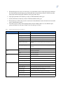
CCTV control systems supported by Picture Perfect . . . . . . . . . . . . . . . . . . . . . . . . . . . . . . . . . . . . . . . . . . . . . . . . . 3
American Dynamics. . . . . . . . . . . . . . . . . . . . . . . . . . . . . . . . . . . . . . . . . . . . . . . . . . . . . . . . . . . . . . . . . . . . . . . . . . . . . . . . . .3
Burle Allegiant . . . . . . . . . . . . . . . . . . . . . . . . . . . . . . . . . . . . . . . . . . . . . . . . . . . . . . . . . . . . . . . . . . . . . . . . . . . . . . . . . . . . . . .3
Burle Allplex . . . . . . . . . . . . . . . . . . . . . . . . . . . . . . . . . . . . . . . . . . . . . . . . . . . . . . . . . . . . . . . . . . . . . . . . . . . . . . . . . . . . . . . . .3
Grundig . . . . . . . . . . . . . . . . . . . . . . . . . . . . . . . . . . . . . . . . . . . . . . . . . . . . . . . . . . . . . . . . . . . . . . . . . . . . . . . . . . . . . . . . . . . . .3
Javelin . . . . . . . . . . . . . . . . . . . . . . . . . . . . . . . . . . . . . . . . . . . . . . . . . . . . . . . . . . . . . . . . . . . . . . . . . . . . . . . . . . . . . . . . . . . . . .3
Kalatel (also known as GE analog video). . . . . . . . . . . . . . . . . . . . . . . . . . . . . . . . . . . . . . . . . . . . . . . . . . . . . . . . . . . . . . .3
MAXPRO . . . . . . . . . . . . . . . . . . . . . . . . . . . . . . . . . . . . . . . . . . . . . . . . . . . . . . . . . . . . . . . . . . . . . . . . . . . . . . . . . . . . . . . . . . . . .3
Panasonic Proteus . . . . . . . . . . . . . . . . . . . . . . . . . . . . . . . . . . . . . . . . . . . . . . . . . . . . . . . . . . . . . . . . . . . . . . . . . . . . . . . . . . .4
Panasonic 550 . . . . . . . . . . . . . . . . . . . . . . . . . . . . . . . . . . . . . . . . . . . . . . . . . . . . . . . . . . . . . . . . . . . . . . . . . . . . . . . . . . . . . . .4
Pelco . . . . . . . . . . . . . . . . . . . . . . . . . . . . . . . . . . . . . . . . . . . . . . . . . . . . . . . . . . . . . . . . . . . . . . . . . . . . . . . . . . . . . . . . . . . . . . . .4
Vicon Viper . . . . . . . . . . . . . . . . . . . . . . . . . . . . . . . . . . . . . . . . . . . . . . . . . . . . . . . . . . . . . . . . . . . . . . . . . . . . . . . . . . . . . . . . . .4
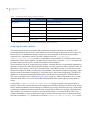
Firepanel systems supported by Picture Perfect . . . . . . . . . . . . . . . . . . . . . . . . . . . . . . . . . . . . . . . . . . . . . . . . . . . . 5
EST . . . . . . . . . . . . . . . . . . . . . . . . . . . . . . . . . . . . . . . . . . . . . . . . . . . . . . . . . . . . . . . . . . . . . . . . . . . . . . . . . . . . . . . . . . . . . . . . . .5
Firesine. . . . . . . . . . . . . . . . . . . . . . . . . . . . . . . . . . . . . . . . . . . . . . . . . . . . . . . . . . . . . . . . . . . . . . . . . . . . . . . . . . . . . . . . . . . . . .5
Notifier . . . . . . . . . . . . . . . . . . . . . . . . . . . . . . . . . . . . . . . . . . . . . . . . . . . . . . . . . . . . . . . . . . . . . . . . . . . . . . . . . . . . . . . . . . . . . .5
Simplex. . . . . . . . . . . . . . . . . . . . . . . . . . . . . . . . . . . . . . . . . . . . . . . . . . . . . . . . . . . . . . . . . . . . . . . . . . . . . . . . . . . . . . . . . . . . . .5
Intrusion detection systems supported by Picture Perfect . . . . . . . . . . . . . . . . . . . . . . . . . . . . . . . . . . . . . . . . . . . 6
DMP SCS . . . . . . . . . . . . . . . . . . . . . . . . . . . . . . . . . . . . . . . . . . . . . . . . . . . . . . . . . . . . . . . . . . . . . . . . . . . . . . . . . . . . . . . . . . . .6
Universal Intrusion . . . . . . . . . . . . . . . . . . . . . . . . . . . . . . . . . . . . . . . . . . . . . . . . . . . . . . . . . . . . . . . . . . . . . . . . . . . . . . . . . . .6
Intercom systems supported by Picture Perfect . . . . . . . . . . . . . . . . . . . . . . . . . . . . . . . . . . . . . . . . . . . . . . . . . . . . 7
AlphaCom . . . . . . . . . . . . . . . . . . . . . . . . . . . . . . . . . . . . . . . . . . . . . . . . . . . . . . . . . . . . . . . . . . . . . . . . . . . . . . . . . . . . . . . . . . .7
Commend . . . . . . . . . . . . . . . . . . . . . . . . . . . . . . . . . . . . . . . . . . . . . . . . . . . . . . . . . . . . . . . . . . . . . . . . . . . . . . . . . . . . . . . . . . .7
Stentofon/Stentofon_MCH . . . . . . . . . . . . . . . . . . . . . . . . . . . . . . . . . . . . . . . . . . . . . . . . . . . . . . . . . . . . . . . . . . . . . . . . . . .7
Stentofon 9600 . . . . . . . . . . . . . . . . . . . . . . . . . . . . . . . . . . . . . . . . . . . . . . . . . . . . . . . . . . . . . . . . . . . . . . . . . . . . . . . . . . . . . .7
Miscellaneous systems supported by Picture Perfect . . . . . . . . . . . . . . . . . . . . . . . . . . . . . . . . . . . . . . . . . . . . . . . . 8
Central Station. . . . . . . . . . . . . . . . . . . . . . . . . . . . . . . . . . . . . . . . . . . . . . . . . . . . . . . . . . . . . . . . . . . . . . . . . . . . . . . . . . . . . . .8
Siebe CBAS . . . . . . . . . . . . . . . . . . . . . . . . . . . . . . . . . . . . . . . . . . . . . . . . . . . . . . . . . . . . . . . . . . . . . . . . . . . . . . . . . . . . . . . . . .8
Remote Alarm Notification . . . . . . . . . . . . . . . . . . . . . . . . . . . . . . . . . . . . . . . . . . . . . . . . . . . . . . . . . . . . . . . . . . . . . . . . . . .8
OH Receiver . . . . . . . . . . . . . . . . . . . . . . . . . . . . . . . . . . . . . . . . . . . . . . . . . . . . . . . . . . . . . . . . . . . . . . . . . . . . . . . . . . . . . . . . .8
iv
Picture Perfect 4.5 Interface
User Manual
Chapter 2.
Installing and removing . . . . . . . . . . . . . . . . . . . . . . . . . . . . . . . . . . . . . . . . . . . . . . . . . 9
Overview . . . . . . . . . . . . . . . . . . . . . . . . . . . . . . . . . . . . . . . . . . . . . . . . . . . . . . . . . . . . . . . . . . . . . . . . . . . . . . . . . . . . . . 10
Defining a port . . . . . . . . . . . . . . . . . . . . . . . . . . . . . . . . . . . . . . . . . . . . . . . . . . . . . . . . . . . . . . . . . . . . . . . . . . . . . . . . . 11
Linux . . . . . . . . . . . . . . . . . . . . . . . . . . . . . . . . . . . . . . . . . . . . . . . . . . . . . . . . . . . . . . . . . . . . . . . . . . . . . . . . . . . . . . . . . . . . . . 11
AIX . . . . . . . . . . . . . . . . . . . . . . . . . . . . . . . . . . . . . . . . . . . . . . . . . . . . . . . . . . . . . . . . . . . . . . . . . . . . . . . . . . . . . . . . . . . . . . . . 11
Installing Picture Perfect base software . . . . . . . . . . . . . . . . . . . . . . . . . . . . . . . . . . . . . . . . . . . . . . . . . . . . . . . . . . 13
Installing on a Redundant system. . . . . . . . . . . . . . . . . . . . . . . . . . . . . . . . . . . . . . . . . . . . . . . . . . . . . . . . . . . . . . . . 13
Installing the interface software . . . . . . . . . . . . . . . . . . . . . . . . . . . . . . . . . . . . . . . . . . . . . . . . . . . . . . . . . . . . . . . . . 14
Configuring ports. . . . . . . . . . . . . . . . . . . . . . . . . . . . . . . . . . . . . . . . . . . . . . . . . . . . . . . . . . . . . . . . . . . . . . . . . . . . . . . . . . . 16
Installing on a Redundant system . . . . . . . . . . . . . . . . . . . . . . . . . . . . . . . . . . . . . . . . . . . . . . . . . . . . . . . . . . . . . . . . . . . 19
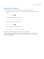
Configuring additional interfaces. . . . . . . . . . . . . . . . . . . . . . . . . . . . . . . . . . . . . . . . . . . . . . . . . . . . . . . . . . . . . . . . . . . . 19
Verifying the installation . . . . . . . . . . . . . . . . . . . . . . . . . . . . . . . . . . . . . . . . . . . . . . . . . . . . . . . . . . . . . . . . . . . . . . . . 21
Removal. . . . . . . . . . . . . . . . . . . . . . . . . . . . . . . . . . . . . . . . . . . . . . . . . . . . . . . . . . . . . . . . . . . . . . . . . . . . . . . . . . . . . . . 22
Redundant systems . . . . . . . . . . . . . . . . . . . . . . . . . . . . . . . . . . . . . . . . . . . . . . . . . . . . . . . . . . . . . . . . . . . . . . . . . . . . . . . . 23
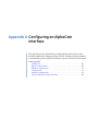
Appendix A. Configuring an AlphaCom interface . . . . . . . . . . . . . . . . . . . . . . . . . . . . . . . . . . . . . 25
Introduction . . . . . . . . . . . . . . . . . . . . . . . . . . . . . . . . . . . . . . . . . . . . . . . . . . . . . . . . . . . . . . . . . . . . . . . . . . . . . . . . . . . 26
Redundant systems . . . . . . . . . . . . . . . . . . . . . . . . . . . . . . . . . . . . . . . . . . . . . . . . . . . . . . . . . . . . . . . . . . . . . . . . . . . . . . . . 26
Software requirements . . . . . . . . . . . . . . . . . . . . . . . . . . . . . . . . . . . . . . . . . . . . . . . . . . . . . . . . . . . . . . . . . . . . . . . . . 26
Stand-alone system . . . . . . . . . . . . . . . . . . . . . . . . . . . . . . . . . . . . . . . . . . . . . . . . . . . . . . . . . . . . . . . . . . . . . . . . . . . . . . . . 26
Redundant system . . . . . . . . . . . . . . . . . . . . . . . . . . . . . . . . . . . . . . . . . . . . . . . . . . . . . . . . . . . . . . . . . . . . . . . . . . . . . . . . . 27
Hardware requirements . . . . . . . . . . . . . . . . . . . . . . . . . . . . . . . . . . . . . . . . . . . . . . . . . . . . . . . . . . . . . . . . . . . . . . . . 27
Stand-alone system . . . . . . . . . . . . . . . . . . . . . . . . . . . . . . . . . . . . . . . . . . . . . . . . . . . . . . . . . . . . . . . . . . . . . . . . . . . . . . . . 27
Redundant system . . . . . . . . . . . . . . . . . . . . . . . . . . . . . . . . . . . . . . . . . . . . . . . . . . . . . . . . . . . . . . . . . . . . . . . . . . . . . . . . . 28
Configuration . . . . . . . . . . . . . . . . . . . . . . . . . . . . . . . . . . . . . . . . . . . . . . . . . . . . . . . . . . . . . . . . . . . . . . . . . . . . . . . . . . 31
Defining input groups . . . . . . . . . . . . . . . . . . . . . . . . . . . . . . . . . . . . . . . . . . . . . . . . . . . . . . . . . . . . . . . . . . . . . . . . . . . . . . 31
Identifying location types . . . . . . . . . . . . . . . . . . . . . . . . . . . . . . . . . . . . . . . . . . . . . . . . . . . . . . . . . . . . . . . . . . . . . . . . . . . 31
Using SQL reports . . . . . . . . . . . . . . . . . . . . . . . . . . . . . . . . . . . . . . . . . . . . . . . . . . . . . . . . . . . . . . . . . . . . . . . . . . . . . . . . . . 32
Mapping CCTV Monitored Events . . . . . . . . . . . . . . . . . . . . . . . . . . . . . . . . . . . . . . . . . . . . . . . . . . . . . . . . . . . . . . . . . . . . 33
Adding an alarm . . . . . . . . . . . . . . . . . . . . . . . . . . . . . . . . . . . . . . . . . . . . . . . . . . . . . . . . . . . . . . . . . . . . . . . . . . . . . . . . . . . 34
Deleting an alarm . . . . . . . . . . . . . . . . . . . . . . . . . . . . . . . . . . . . . . . . . . . . . . . . . . . . . . . . . . . . . . . . . . . . . . . . . . . . . . . . . . 37
Changing an alarm . . . . . . . . . . . . . . . . . . . . . . . . . . . . . . . . . . . . . . . . . . . . . . . . . . . . . . . . . . . . . . . . . . . . . . . . . . . . . . . . . 38
Printing the map file . . . . . . . . . . . . . . . . . . . . . . . . . . . . . . . . . . . . . . . . . . . . . . . . . . . . . . . . . . . . . . . . . . . . . . . . . . . . . . . . 38
Exiting the program . . . . . . . . . . . . . . . . . . . . . . . . . . . . . . . . . . . . . . . . . . . . . . . . . . . . . . . . . . . . . . . . . . . . . . . . . . . . . . . . 40
Advanced configuration . . . . . . . . . . . . . . . . . . . . . . . . . . . . . . . . . . . . . . . . . . . . . . . . . . . . . . . . . . . . . . . . . . . . . . . . 41
Single device support. . . . . . . . . . . . . . . . . . . . . . . . . . . . . . . . . . . . . . . . . . . . . . . . . . . . . . . . . . . . . . . . . . . . . . . . . . . . . . . 44
Multiple device support issues . . . . . . . . . . . . . . . . . . . . . . . . . . . . . . . . . . . . . . . . . . . . . . . . . . . . . . . . . . . . . . . . . . . . . . 44
Multiple device support . . . . . . . . . . . . . . . . . . . . . . . . . . . . . . . . . . . . . . . . . . . . . . . . . . . . . . . . . . . . . . . . . . . . . . . . . . . . . 45
Interface data file backup and restore. . . . . . . . . . . . . . . . . . . . . . . . . . . . . . . . . . . . . . . . . . . . . . . . . . . . . . . . . . . . 46
v
Appendix B. Configuring a CCTV interface. . . . . . . . . . . . . . . . . . . . . . . . . . . . . . . . . . . . . . . . . . . . 47
Introduction . . . . . . . . . . . . . . . . . . . . . . . . . . . . . . . . . . . . . . . . . . . . . . . . . . . . . . . . . . . . . . . . . . . . . . . . . . . . . . . . . . . 48
Redundant systems . . . . . . . . . . . . . . . . . . . . . . . . . . . . . . . . . . . . . . . . . . . . . . . . . . . . . . . . . . . . . . . . . . . . . . . . . . . . . . . . 48
Software requirements. . . . . . . . . . . . . . . . . . . . . . . . . . . . . . . . . . . . . . . . . . . . . . . . . . . . . . . . . . . . . . . . . . . . . . . . . . 49
Stand-alone system. . . . . . . . . . . . . . . . . . . . . . . . . . . . . . . . . . . . . . . . . . . . . . . . . . . . . . . . . . . . . . . . . . . . . . . . . . . . . . . . 49
Redundant system . . . . . . . . . . . . . . . . . . . . . . . . . . . . . . . . . . . . . . . . . . . . . . . . . . . . . . . . . . . . . . . . . . . . . . . . . . . . . . . . . 49
Hardware requirements. . . . . . . . . . . . . . . . . . . . . . . . . . . . . . . . . . . . . . . . . . . . . . . . . . . . . . . . . . . . . . . . . . . . . . . . . 50
Stand-alone system. . . . . . . . . . . . . . . . . . . . . . . . . . . . . . . . . . . . . . . . . . . . . . . . . . . . . . . . . . . . . . . . . . . . . . . . . . . . . . . . 50
Redundant system . . . . . . . . . . . . . . . . . . . . . . . . . . . . . . . . . . . . . . . . . . . . . . . . . . . . . . . . . . . . . . . . . . . . . . . . . . . . . . . . . 55
Configuration . . . . . . . . . . . . . . . . . . . . . . . . . . . . . . . . . . . . . . . . . . . . . . . . . . . . . . . . . . . . . . . . . . . . . . . . . . . . . . . . . . 58
Defining input groups . . . . . . . . . . . . . . . . . . . . . . . . . . . . . . . . . . . . . . . . . . . . . . . . . . . . . . . . . . . . . . . . . . . . . . . . . . . . . . 58
Identifying location types. . . . . . . . . . . . . . . . . . . . . . . . . . . . . . . . . . . . . . . . . . . . . . . . . . . . . . . . . . . . . . . . . . . . . . . . . . . 59
Using SQL reports . . . . . . . . . . . . . . . . . . . . . . . . . . . . . . . . . . . . . . . . . . . . . . . . . . . . . . . . . . . . . . . . . . . . . . . . . . . . . . . . . . 60
Mapping CCTV monitored events . . . . . . . . . . . . . . . . . . . . . . . . . . . . . . . . . . . . . . . . . . . . . . . . . . . . . . . . . . . . . . . . . . . 61
Configuring and monitoring alarms in Picture Perfect . . . . . . . . . . . . . . . . . . . . . . . . . . . . . . . . . . . . . . . . . . . . . . . . 69
Advanced configuration. . . . . . . . . . . . . . . . . . . . . . . . . . . . . . . . . . . . . . . . . . . . . . . . . . . . . . . . . . . . . . . . . . . . . . . . . 69
Single device support . . . . . . . . . . . . . . . . . . . . . . . . . . . . . . . . . . . . . . . . . . . . . . . . . . . . . . . . . . . . . . . . . . . . . . . . . . . . . . 70
Multiple device support. . . . . . . . . . . . . . . . . . . . . . . . . . . . . . . . . . . . . . . . . . . . . . . . . . . . . . . . . . . . . . . . . . . . . . . . . . . . . 71
Interface data file backup and restore . . . . . . . . . . . . . . . . . . . . . . . . . . . . . . . . . . . . . . . . . . . . . . . . . . . . . . . . . . . . 72
Appendix C. Configuring a Central Station interface . . . . . . . . . . . . . . . . . . . . . . . . . . . . . . . . . . 73
Introduction . . . . . . . . . . . . . . . . . . . . . . . . . . . . . . . . . . . . . . . . . . . . . . . . . . . . . . . . . . . . . . . . . . . . . . . . . . . . . . . . . . . 74
Software requirements . . . . . . . . . . . . . . . . . . . . . . . . . . . . . . . . . . . . . . . . . . . . . . . . . . . . . . . . . . . . . . . . . . . . . . . . . . . . . 74
Hardware requirements . . . . . . . . . . . . . . . . . . . . . . . . . . . . . . . . . . . . . . . . . . . . . . . . . . . . . . . . . . . . . . . . . . . . . . . . . . . . 74
Configuration . . . . . . . . . . . . . . . . . . . . . . . . . . . . . . . . . . . . . . . . . . . . . . . . . . . . . . . . . . . . . . . . . . . . . . . . . . . . . . . . . . 76
Creating Picture Perfect alarms . . . . . . . . . . . . . . . . . . . . . . . . . . . . . . . . . . . . . . . . . . . . . . . . . . . . . . . . . . . . . . . . . . . . . 76
Assigning account numbers . . . . . . . . . . . . . . . . . . . . . . . . . . . . . . . . . . . . . . . . . . . . . . . . . . . . . . . . . . . . . . . . . . . . . . . . 78
Creating an input file . . . . . . . . . . . . . . . . . . . . . . . . . . . . . . . . . . . . . . . . . . . . . . . . . . . . . . . . . . . . . . . . . . . . . . . . . . . . . . . 79
Running the cstgen tool . . . . . . . . . . . . . . . . . . . . . . . . . . . . . . . . . . . . . . . . . . . . . . . . . . . . . . . . . . . . . . . . . . . . . . . . . . . . 83
Advanced configuration. . . . . . . . . . . . . . . . . . . . . . . . . . . . . . . . . . . . . . . . . . . . . . . . . . . . . . . . . . . . . . . . . . . . . . . . . 84
Multiple device support issues . . . . . . . . . . . . . . . . . . . . . . . . . . . . . . . . . . . . . . . . . . . . . . . . . . . . . . . . . . . . . . . . . . . . . . 85
Single device support . . . . . . . . . . . . . . . . . . . . . . . . . . . . . . . . . . . . . . . . . . . . . . . . . . . . . . . . . . . . . . . . . . . . . . . . . . . . . . 86
Interface data file backup and restore . . . . . . . . . . . . . . . . . . . . . . . . . . . . . . . . . . . . . . . . . . . . . . . . . . . . . . . . . . . . . . 87
Picture Perfect output to the Central Station system . . . . . . . . . . . . . . . . . . . . . . . . . . . . . . . . . . . . . . . . . . . . . . . . . 87
Interface port requirements . . . . . . . . . . . . . . . . . . . . . . . . . . . . . . . . . . . . . . . . . . . . . . . . . . . . . . . . . . . . . . . . . . . . . . . . 87
Interface design and operation . . . . . . . . . . . . . . . . . . . . . . . . . . . . . . . . . . . . . . . . . . . . . . . . . . . . . . . . . . . . . . . . . . . . . 88
Alarm event triggering of SIA message output . . . . . . . . . . . . . . . . . . . . . . . . . . . . . . . . . . . . . . . . . . . . . . . . . . . . . . . 88
SIA message packet format . . . . . . . . . . . . . . . . . . . . . . . . . . . . . . . . . . . . . . . . . . . . . . . . . . . . . . . . . . . . . . . . . . . . . . . . 89
Interface specific message packet format. . . . . . . . . . . . . . . . . . . . . . . . . . . . . . . . . . . . . . . . . . . . . . . . . . . . . . . . . . . 90
Communications failures . . . . . . . . . . . . . . . . . . . . . . . . . . . . . . . . . . . . . . . . . . . . . . . . . . . . . . . . . . . . . . . . . . . . . . . . . . . 91
Message processing . . . . . . . . . . . . . . . . . . . . . . . . . . . . . . . . . . . . . . . . . . . . . . . . . . . . . . . . . . . . . . . . . . . . . . . . . . . . . . . 91
vi
Picture Perfect 4.5 Interface
User Manual
Appendix D. Configuring a Commend interface . . . . . . . . . . . . . . . . . . . . . . . . . . . . . . . . . . . . . . . 93
Introduction . . . . . . . . . . . . . . . . . . . . . . . . . . . . . . . . . . . . . . . . . . . . . . . . . . . . . . . . . . . . . . . . . . . . . . . . . . . . . . . . . . . 94
Redundant systems . . . . . . . . . . . . . . . . . . . . . . . . . . . . . . . . . . . . . . . . . . . . . . . . . . . . . . . . . . . . . . . . . . . . . . . . . . . . . . . . 94
Software requirements . . . . . . . . . . . . . . . . . . . . . . . . . . . . . . . . . . . . . . . . . . . . . . . . . . . . . . . . . . . . . . . . . . . . . . . . . 95
Stand-alone system . . . . . . . . . . . . . . . . . . . . . . . . . . . . . . . . . . . . . . . . . . . . . . . . . . . . . . . . . . . . . . . . . . . . . . . . . . . . . . . . 95
Redundant system . . . . . . . . . . . . . . . . . . . . . . . . . . . . . . . . . . . . . . . . . . . . . . . . . . . . . . . . . . . . . . . . . . . . . . . . . . . . . . . . . 95
Hardware requirements . . . . . . . . . . . . . . . . . . . . . . . . . . . . . . . . . . . . . . . . . . . . . . . . . . . . . . . . . . . . . . . . . . . . . . . . 96
Stand-alone system . . . . . . . . . . . . . . . . . . . . . . . . . . . . . . . . . . . . . . . . . . . . . . . . . . . . . . . . . . . . . . . . . . . . . . . . . . . . . . . . 96
Redundant system . . . . . . . . . . . . . . . . . . . . . . . . . . . . . . . . . . . . . . . . . . . . . . . . . . . . . . . . . . . . . . . . . . . . . . . . . . . . . . . . . 97
Configuration . . . . . . . . . . . . . . . . . . . . . . . . . . . . . . . . . . . . . . . . . . . . . . . . . . . . . . . . . . . . . . . . . . . . . . . . . . . . . . . . . . 99
Using cmdgen . . . . . . . . . . . . . . . . . . . . . . . . . . . . . . . . . . . . . . . . . . . . . . . . . . . . . . . . . . . . . . . . . . . . . . . . . . . . . . . . . . . . . 99
Cmdgen – uninstall . . . . . . . . . . . . . . . . . . . . . . . . . . . . . . . . . . . . . . . . . . . . . . . . . . . . . . . . . . . . . . . . . . . . . . . . . . . . . . . .108
Using Picture Perfect to configure the Commend interface . . . . . . . . . . . . . . . . . . . . . . . . . . . . . . . . . . . . . . . . . .110
Commend Intercom System Message Structure . . . . . . . . . . . . . . . . . . . . . . . . . . . . . . . . . . . . . . . . . . . . . . . . . . . .117
Appendix E. Configuring a DMP SCS interface . . . . . . . . . . . . . . . . . . . . . . . . . . . . . . . . . . . . . . . 119
Introduction . . . . . . . . . . . . . . . . . . . . . . . . . . . . . . . . . . . . . . . . . . . . . . . . . . . . . . . . . . . . . . . . . . . . . . . . . . . . . . . . . . 120
Redundant Systems . . . . . . . . . . . . . . . . . . . . . . . . . . . . . . . . . . . . . . . . . . . . . . . . . . . . . . . . . . . . . . . . . . . . . . . . . . . . . . .120
Software requirements . . . . . . . . . . . . . . . . . . . . . . . . . . . . . . . . . . . . . . . . . . . . . . . . . . . . . . . . . . . . . . . . . . . . . . . . 121
Stand-alone system . . . . . . . . . . . . . . . . . . . . . . . . . . . . . . . . . . . . . . . . . . . . . . . . . . . . . . . . . . . . . . . . . . . . . . . . . . . . . . .121
Redundant system . . . . . . . . . . . . . . . . . . . . . . . . . . . . . . . . . . . . . . . . . . . . . . . . . . . . . . . . . . . . . . . . . . . . . . . . . . . . . . . .121
Hardware requirements . . . . . . . . . . . . . . . . . . . . . . . . . . . . . . . . . . . . . . . . . . . . . . . . . . . . . . . . . . . . . . . . . . . . . . . 122
Stand-alone system . . . . . . . . . . . . . . . . . . . . . . . . . . . . . . . . . . . . . . . . . . . . . . . . . . . . . . . . . . . . . . . . . . . . . . . . . . . . . . .122
Redundant system . . . . . . . . . . . . . . . . . . . . . . . . . . . . . . . . . . . . . . . . . . . . . . . . . . . . . . . . . . . . . . . . . . . . . . . . . . . . . . . .123
Configuring DMP SCS-1 . . . . . . . . . . . . . . . . . . . . . . . . . . . . . . . . . . . . . . . . . . . . . . . . . . . . . . . . . . . . . . . . . . . . . . . . 126
Using the scsgen Data Generator Tool . . . . . . . . . . . . . . . . . . . . . . . . . . . . . . . . . . . . . . . . . . . . . . . . . . . . . . . . . . . . .126
Using Picture Perfect to configure the DMP SCS-1 interface . . . . . . . . . . . . . . . . . . . . . . . . . . . . . . . . . . . . . . . . .150
Testing the interface. . . . . . . . . . . . . . . . . . . . . . . . . . . . . . . . . . . . . . . . . . . . . . . . . . . . . . . . . . . . . . . . . . . . . . . . . . . . . . .161
Advanced configuration . . . . . . . . . . . . . . . . . . . . . . . . . . . . . . . . . . . . . . . . . . . . . . . . . . . . . . . . . . . . . . . . . . . . . . . 162
/cas/db/text/scs_ttyN.cfg. . . . . . . . . . . . . . . . . . . . . . . . . . . . . . . . . . . . . . . . . . . . . . . . . . . . . . . . . . . . . . . . . . . . . . . . . .162
/cas/db/text/scs_signals_ttyN.cfg or /cas/db/text/scs_signals.cfg . . . . . . . . . . . . . . . . . . . . . . . . . . . . . . . . . . .164
/cas/db/text/scs.redundant.cfg . . . . . . . . . . . . . . . . . . . . . . . . . . . . . . . . . . . . . . . . . . . . . . . . . . . . . . . . . . . . . . . . . . . .165
Interface data file backup and restore. . . . . . . . . . . . . . . . . . . . . . . . . . . . . . . . . . . . . . . . . . . . . . . . . . . . . . . . . . . 165
vii
Appendix F. Configuring an EST interface . . . . . . . . . . . . . . . . . . . . . . . . . . . . . . . . . . . . . . . . . . . 167
Introduction . . . . . . . . . . . . . . . . . . . . . . . . . . . . . . . . . . . . . . . . . . . . . . . . . . . . . . . . . . . . . . . . . . . . . . . . . . . . . . . . . .168
Redundant Systems. . . . . . . . . . . . . . . . . . . . . . . . . . . . . . . . . . . . . . . . . . . . . . . . . . . . . . . . . . . . . . . . . . . . . . . . . . . . . . . 168
Software requirements. . . . . . . . . . . . . . . . . . . . . . . . . . . . . . . . . . . . . . . . . . . . . . . . . . . . . . . . . . . . . . . . . . . . . . . . .169
Stand-alone system. . . . . . . . . . . . . . . . . . . . . . . . . . . . . . . . . . . . . . . . . . . . . . . . . . . . . . . . . . . . . . . . . . . . . . . . . . . . . . . 169
Redundant system . . . . . . . . . . . . . . . . . . . . . . . . . . . . . . . . . . . . . . . . . . . . . . . . . . . . . . . . . . . . . . . . . . . . . . . . . . . . . . . . 169
Hardware requirements. . . . . . . . . . . . . . . . . . . . . . . . . . . . . . . . . . . . . . . . . . . . . . . . . . . . . . . . . . . . . . . . . . . . . . . .169
Stand-alone system. . . . . . . . . . . . . . . . . . . . . . . . . . . . . . . . . . . . . . . . . . . . . . . . . . . . . . . . . . . . . . . . . . . . . . . . . . . . . . . 169
Redundant system . . . . . . . . . . . . . . . . . . . . . . . . . . . . . . . . . . . . . . . . . . . . . . . . . . . . . . . . . . . . . . . . . . . . . . . . . . . . . . . . 170
EST configuration. . . . . . . . . . . . . . . . . . . . . . . . . . . . . . . . . . . . . . . . . . . . . . . . . . . . . . . . . . . . . . . . . . . . . . . . . . . . . .173
Alarms recognized by the EST interface . . . . . . . . . . . . . . . . . . . . . . . . . . . . . . . . . . . . . . . . . . . . . . . . . . . . . . . . . . . . 173
Using Picture Perfect to configure the EST interface . . . . . . . . . . . . . . . . . . . . . . . . . . . . . . . . . . . . . . . . . . . . . . . . 174
Adding an input group . . . . . . . . . . . . . . . . . . . . . . . . . . . . . . . . . . . . . . . . . . . . . . . . . . . . . . . . . . . . . . . . . . . . . . . . . . . . 175
Modifying an input group. . . . . . . . . . . . . . . . . . . . . . . . . . . . . . . . . . . . . . . . . . . . . . . . . . . . . . . . . . . . . . . . . . . . . . . . . . 177
Adding or modifying an alarm . . . . . . . . . . . . . . . . . . . . . . . . . . . . . . . . . . . . . . . . . . . . . . . . . . . . . . . . . . . . . . . . . . . . . 177
Adding or modifying output groups and outputs. . . . . . . . . . . . . . . . . . . . . . . . . . . . . . . . . . . . . . . . . . . . . . . . . . . . 179
EST alarm mapping to the alarm monitor . . . . . . . . . . . . . . . . . . . . . . . . . . . . . . . . . . . . . . . . . . . . . . . . . . . . . . . . . . 180
EST3 configuration . . . . . . . . . . . . . . . . . . . . . . . . . . . . . . . . . . . . . . . . . . . . . . . . . . . . . . . . . . . . . . . . . . . . . . . . . . . .181
Advanced configuration. . . . . . . . . . . . . . . . . . . . . . . . . . . . . . . . . . . . . . . . . . . . . . . . . . . . . . . . . . . . . . . . . . . . . . . .184
Appendix G. Configuring a Firesine interface . . . . . . . . . . . . . . . . . . . . . . . . . . . . . . . . . . . . . . . . 187
Introduction . . . . . . . . . . . . . . . . . . . . . . . . . . . . . . . . . . . . . . . . . . . . . . . . . . . . . . . . . . . . . . . . . . . . . . . . . . . . . . . . . .188
Redundant systems . . . . . . . . . . . . . . . . . . . . . . . . . . . . . . . . . . . . . . . . . . . . . . . . . . . . . . . . . . . . . . . . . . . . . . . . . . . . . . . 188
Software requirements. . . . . . . . . . . . . . . . . . . . . . . . . . . . . . . . . . . . . . . . . . . . . . . . . . . . . . . . . . . . . . . . . . . . . . . . .189
Stand-alone system. . . . . . . . . . . . . . . . . . . . . . . . . . . . . . . . . . . . . . . . . . . . . . . . . . . . . . . . . . . . . . . . . . . . . . . . . . . . . . . 189
Redundant system . . . . . . . . . . . . . . . . . . . . . . . . . . . . . . . . . . . . . . . . . . . . . . . . . . . . . . . . . . . . . . . . . . . . . . . . . . . . . . . . 189
Hardware requirements. . . . . . . . . . . . . . . . . . . . . . . . . . . . . . . . . . . . . . . . . . . . . . . . . . . . . . . . . . . . . . . . . . . . . . . .189
Stand-alone system. . . . . . . . . . . . . . . . . . . . . . . . . . . . . . . . . . . . . . . . . . . . . . . . . . . . . . . . . . . . . . . . . . . . . . . . . . . . . . . 189
Redundant system . . . . . . . . . . . . . . . . . . . . . . . . . . . . . . . . . . . . . . . . . . . . . . . . . . . . . . . . . . . . . . . . . . . . . . . . . . . . . . . . 190
Configuration . . . . . . . . . . . . . . . . . . . . . . . . . . . . . . . . . . . . . . . . . . . . . . . . . . . . . . . . . . . . . . . . . . . . . . . . . . . . . . . . .193
Firesine message structure . . . . . . . . . . . . . . . . . . . . . . . . . . . . . . . . . . . . . . . . . . . . . . . . . . . . . . . . . . . . . . . . . . . . . . . . 193
Picture perfect input group description. . . . . . . . . . . . . . . . . . . . . . . . . . . . . . . . . . . . . . . . . . . . . . . . . . . . . . . . . . . . . 194
Adding or modifying an input group . . . . . . . . . . . . . . . . . . . . . . . . . . . . . . . . . . . . . . . . . . . . . . . . . . . . . . . . . . . . . . . 194
Adding or modifying an alarm . . . . . . . . . . . . . . . . . . . . . . . . . . . . . . . . . . . . . . . . . . . . . . . . . . . . . . . . . . . . . . . . . . . . . 196
Monitoring alarms . . . . . . . . . . . . . . . . . . . . . . . . . . . . . . . . . . . . . . . . . . . . . . . . . . . . . . . . . . . . . . . . . . . . . . . . . . . . . . . . 198
Advanced configuration. . . . . . . . . . . . . . . . . . . . . . . . . . . . . . . . . . . . . . . . . . . . . . . . . . . . . . . . . . . . . . . . . . . . . . . .199
viii
Picture Perfect 4.5 Interface
User Manual
Appendix H. Configuring a Notifier interface . . . . . . . . . . . . . . . . . . . . . . . . . . . . . . . . . . . . . . . . 201
Introduction . . . . . . . . . . . . . . . . . . . . . . . . . . . . . . . . . . . . . . . . . . . . . . . . . . . . . . . . . . . . . . . . . . . . . . . . . . . . . . . . . . 202
Redundant systems . . . . . . . . . . . . . . . . . . . . . . . . . . . . . . . . . . . . . . . . . . . . . . . . . . . . . . . . . . . . . . . . . . . . . . . . . . . . . . .202
Software requirements . . . . . . . . . . . . . . . . . . . . . . . . . . . . . . . . . . . . . . . . . . . . . . . . . . . . . . . . . . . . . . . . . . . . . . . . 203
Stand-alone system . . . . . . . . . . . . . . . . . . . . . . . . . . . . . . . . . . . . . . . . . . . . . . . . . . . . . . . . . . . . . . . . . . . . . . . . . . . . . . .203
Redundant system . . . . . . . . . . . . . . . . . . . . . . . . . . . . . . . . . . . . . . . . . . . . . . . . . . . . . . . . . . . . . . . . . . . . . . . . . . . . . . . .203
Hardware requirements . . . . . . . . . . . . . . . . . . . . . . . . . . . . . . . . . . . . . . . . . . . . . . . . . . . . . . . . . . . . . . . . . . . . . . . 204
Stand-alone system . . . . . . . . . . . . . . . . . . . . . . . . . . . . . . . . . . . . . . . . . . . . . . . . . . . . . . . . . . . . . . . . . . . . . . . . . . . . . . .204
Redundant system . . . . . . . . . . . . . . . . . . . . . . . . . . . . . . . . . . . . . . . . . . . . . . . . . . . . . . . . . . . . . . . . . . . . . . . . . . . . . . . .206
Configuration . . . . . . . . . . . . . . . . . . . . . . . . . . . . . . . . . . . . . . . . . . . . . . . . . . . . . . . . . . . . . . . . . . . . . . . . . . . . . . . . . 209
Using nfrgen . . . . . . . . . . . . . . . . . . . . . . . . . . . . . . . . . . . . . . . . . . . . . . . . . . . . . . . . . . . . . . . . . . . . . . . . . . . . . . . . . . . . . .209
nfrgen – install . . . . . . . . . . . . . . . . . . . . . . . . . . . . . . . . . . . . . . . . . . . . . . . . . . . . . . . . . . . . . . . . . . . . . . . . . . . . . . . . . . . .209
Using nfrgen – install . . . . . . . . . . . . . . . . . . . . . . . . . . . . . . . . . . . . . . . . . . . . . . . . . . . . . . . . . . . . . . . . . . . . . . . . . . . . . .217
Using nfrgen to generate new device data after an initial installation . . . . . . . . . . . . . . . . . . . . . . . . . . . . . . . .221
Using nfrgen to change or add message types for an existing device after an initial installation . . . . . . .221
nfrgen – uninstall. . . . . . . . . . . . . . . . . . . . . . . . . . . . . . . . . . . . . . . . . . . . . . . . . . . . . . . . . . . . . . . . . . . . . . . . . . . . . . . . . .222
Using Picture Perfect to configure the Notifier interface . . . . . . . . . . . . . . . . . . . . . . . . . . . . . . . . . . . . . . . . . . . . .224
Device types . . . . . . . . . . . . . . . . . . . . . . . . . . . . . . . . . . . . . . . . . . . . . . . . . . . . . . . . . . . . . . . . . . . . . . . . . . . . . . . . . . 236
Testing the interface . . . . . . . . . . . . . . . . . . . . . . . . . . . . . . . . . . . . . . . . . . . . . . . . . . . . . . . . . . . . . . . . . . . . . . . . . . 237
Advanced configuration . . . . . . . . . . . . . . . . . . . . . . . . . . . . . . . . . . . . . . . . . . . . . . . . . . . . . . . . . . . . . . . . . . . . . . . 238
/cas/db/text/notifier_ttyN.cfg . . . . . . . . . . . . . . . . . . . . . . . . . . . . . . . . . . . . . . . . . . . . . . . . . . . . . . . . . . . . . . . . . . . . . .238
/cas/db/text/notifier.redundant.cfg . . . . . . . . . . . . . . . . . . . . . . . . . . . . . . . . . . . . . . . . . . . . . . . . . . . . . . . . . . . . . . . .239
Interface data file backup and restore. . . . . . . . . . . . . . . . . . . . . . . . . . . . . . . . . . . . . . . . . . . . . . . . . . . . . . . . . . . 240
Appendix I.
Configuring an OH Receiver interface . . . . . . . . . . . . . . . . . . . . . . . . . . . . . . . . . . . 241
Introduction . . . . . . . . . . . . . . . . . . . . . . . . . . . . . . . . . . . . . . . . . . . . . . . . . . . . . . . . . . . . . . . . . . . . . . . . . . . . . . . . . . 242
Redundant systems . . . . . . . . . . . . . . . . . . . . . . . . . . . . . . . . . . . . . . . . . . . . . . . . . . . . . . . . . . . . . . . . . . . . . . . . . . . . . . .242
Software requirements . . . . . . . . . . . . . . . . . . . . . . . . . . . . . . . . . . . . . . . . . . . . . . . . . . . . . . . . . . . . . . . . . . . . . . . . 243
Stand-alone system . . . . . . . . . . . . . . . . . . . . . . . . . . . . . . . . . . . . . . . . . . . . . . . . . . . . . . . . . . . . . . . . . . . . . . . . . . . . . . .243
Redundant system . . . . . . . . . . . . . . . . . . . . . . . . . . . . . . . . . . . . . . . . . . . . . . . . . . . . . . . . . . . . . . . . . . . . . . . . . . . . . . . .243
Hardware requirements . . . . . . . . . . . . . . . . . . . . . . . . . . . . . . . . . . . . . . . . . . . . . . . . . . . . . . . . . . . . . . . . . . . . . . . 244
Stand-alone system . . . . . . . . . . . . . . . . . . . . . . . . . . . . . . . . . . . . . . . . . . . . . . . . . . . . . . . . . . . . . . . . . . . . . . . . . . . . . . .244
Redundant system . . . . . . . . . . . . . . . . . . . . . . . . . . . . . . . . . . . . . . . . . . . . . . . . . . . . . . . . . . . . . . . . . . . . . . . . . . . . . . . .246
Configuration . . . . . . . . . . . . . . . . . . . . . . . . . . . . . . . . . . . . . . . . . . . . . . . . . . . . . . . . . . . . . . . . . . . . . . . . . . . . . . . . . 250
Input group records . . . . . . . . . . . . . . . . . . . . . . . . . . . . . . . . . . . . . . . . . . . . . . . . . . . . . . . . . . . . . . . . . . . . . . . . . . . . . . .250
Alarm records . . . . . . . . . . . . . . . . . . . . . . . . . . . . . . . . . . . . . . . . . . . . . . . . . . . . . . . . . . . . . . . . . . . . . . . . . . . . . . . . . . . . .253
Output group and output records . . . . . . . . . . . . . . . . . . . . . . . . . . . . . . . . . . . . . . . . . . . . . . . . . . . . . . . . . . . . . . . . . .255
Monitoring alarms. . . . . . . . . . . . . . . . . . . . . . . . . . . . . . . . . . . . . . . . . . . . . . . . . . . . . . . . . . . . . . . . . . . . . . . . . . . . . . . . .255
Monitoring events . . . . . . . . . . . . . . . . . . . . . . . . . . . . . . . . . . . . . . . . . . . . . . . . . . . . . . . . . . . . . . . . . . . . . . . . . . . . . . . . .256
Testing the interface . . . . . . . . . . . . . . . . . . . . . . . . . . . . . . . . . . . . . . . . . . . . . . . . . . . . . . . . . . . . . . . . . . . . . . . . . . 256
Extended configuration . . . . . . . . . . . . . . . . . . . . . . . . . . . . . . . . . . . . . . . . . . . . . . . . . . . . . . . . . . . . . . . . . . . . . . . . 256
/cas/db/text/oh_receiver_ttyN.cfg . . . . . . . . . . . . . . . . . . . . . . . . . . . . . . . . . . . . . . . . . . . . . . . . . . . . . . . . . . . . . . . . .256
/cas/db/text/oh_receiver.redundant.cfg . . . . . . . . . . . . . . . . . . . . . . . . . . . . . . . . . . . . . . . . . . . . . . . . . . . . . . . . . . .257
Interface data file backup and restore. . . . . . . . . . . . . . . . . . . . . . . . . . . . . . . . . . . . . . . . . . . . . . . . . . . . . . . . . . . 258
ix
Appendix J. Configuring a Siebe CBAS interface . . . . . . . . . . . . . . . . . . . . . . . . . . . . . . . . . . . . . 259
Introduction . . . . . . . . . . . . . . . . . . . . . . . . . . . . . . . . . . . . . . . . . . . . . . . . . . . . . . . . . . . . . . . . . . . . . . . . . . . . . . . . . .260
Redundant systems . . . . . . . . . . . . . . . . . . . . . . . . . . . . . . . . . . . . . . . . . . . . . . . . . . . . . . . . . . . . . . . . . . . . . . . . . . . . . . . 260
Software requirements . . . . . . . . . . . . . . . . . . . . . . . . . . . . . . . . . . . . . . . . . . . . . . . . . . . . . . . . . . . . . . . . . . . . . . . . . . . . 260
Hardware requirements . . . . . . . . . . . . . . . . . . . . . . . . . . . . . . . . . . . . . . . . . . . . . . . . . . . . . . . . . . . . . . . . . . . . . . . . . . . 261
Extended configuration . . . . . . . . . . . . . . . . . . . . . . . . . . . . . . . . . . . . . . . . . . . . . . . . . . . . . . . . . . . . . . . . . . . . . . . .266
/cas/db/text/cbas_ttyN.cfg . . . . . . . . . . . . . . . . . . . . . . . . . . . . . . . . . . . . . . . . . . . . . . . . . . . . . . . . . . . . . . . . . . . . . . . . 266
/cas/db/text/cbas.redundant.cfg . . . . . . . . . . . . . . . . . . . . . . . . . . . . . . . . . . . . . . . . . . . . . . . . . . . . . . . . . . . . . . . . . . 267
Interface data file backup and restore . . . . . . . . . . . . . . . . . . . . . . . . . . . . . . . . . . . . . . . . . . . . . . . . . . . . . . . . . . .267
Appendix K. Configuring a Remote Alarm Notification interface . . . . . . . . . . . . . . . . . . . . . . . 269
Introduction . . . . . . . . . . . . . . . . . . . . . . . . . . . . . . . . . . . . . . . . . . . . . . . . . . . . . . . . . . . . . . . . . . . . . . . . . . . . . . . . . .270
Standalone . . . . . . . . . . . . . . . . . . . . . . . . . . . . . . . . . . . . . . . . . . . . . . . . . . . . . . . . . . . . . . . . . . . . . . . . . . . . . . . . . . . . . . . 270
Networked . . . . . . . . . . . . . . . . . . . . . . . . . . . . . . . . . . . . . . . . . . . . . . . . . . . . . . . . . . . . . . . . . . . . . . . . . . . . . . . . . . . . . . . 270
Redundant . . . . . . . . . . . . . . . . . . . . . . . . . . . . . . . . . . . . . . . . . . . . . . . . . . . . . . . . . . . . . . . . . . . . . . . . . . . . . . . . . . . . . . . 271
Software requirements. . . . . . . . . . . . . . . . . . . . . . . . . . . . . . . . . . . . . . . . . . . . . . . . . . . . . . . . . . . . . . . . . . . . . . . . .271
Stand-alone system. . . . . . . . . . . . . . . . . . . . . . . . . . . . . . . . . . . . . . . . . . . . . . . . . . . . . . . . . . . . . . . . . . . . . . . . . . . . . . . 271
Redundant system . . . . . . . . . . . . . . . . . . . . . . . . . . . . . . . . . . . . . . . . . . . . . . . . . . . . . . . . . . . . . . . . . . . . . . . . . . . . . . . . 271
Hardware overview . . . . . . . . . . . . . . . . . . . . . . . . . . . . . . . . . . . . . . . . . . . . . . . . . . . . . . . . . . . . . . . . . . . . . . . . . . . .272
Configuration . . . . . . . . . . . . . . . . . . . . . . . . . . . . . . . . . . . . . . . . . . . . . . . . . . . . . . . . . . . . . . . . . . . . . . . . . . . . . . . . .273
Configuring alarm routing criteria. . . . . . . . . . . . . . . . . . . . . . . . . . . . . . . . . . . . . . . . . . . . . . . . . . . . . . . . . . . . . . . . . . 273
Remote Connection Lost Alarm . . . . . . . . . . . . . . . . . . . . . . . . . . . . . . . . . . . . . . . . . . . . . . . . . . . . . . . . . . . . . . . . . . . . 274
Advanced configuration. . . . . . . . . . . . . . . . . . . . . . . . . . . . . . . . . . . . . . . . . . . . . . . . . . . . . . . . . . . . . . . . . . . . . . . .277
How long to wait for a connection . . . . . . . . . . . . . . . . . . . . . . . . . . . . . . . . . . . . . . . . . . . . . . . . . . . . . . . . . . . . . . . . . 279
Options for CONN lost alarms. . . . . . . . . . . . . . . . . . . . . . . . . . . . . . . . . . . . . . . . . . . . . . . . . . . . . . . . . . . . . . . . . . . . . . 279
What Happens When the Connection is Lost . . . . . . . . . . . . . . . . . . . . . . . . . . . . . . . . . . . . . . . . . . . . . . . . . . . . . . . 279
Alarm response states . . . . . . . . . . . . . . . . . . . . . . . . . . . . . . . . . . . . . . . . . . . . . . . . . . . . . . . . . . . . . . . . . . . . . . . . . . . . 280
TCP/IP configuration . . . . . . . . . . . . . . . . . . . . . . . . . . . . . . . . . . . . . . . . . . . . . . . . . . . . . . . . . . . . . . . . . . . . . . . . . . . . . . 280
Message format from Picture Perfect (Version 1.55 or higher) . . . . . . . . . . . . . . . . . . . . . . . . . . . . . . . . . . . . . . . 281
Message format from the remote system . . . . . . . . . . . . . . . . . . . . . . . . . . . . . . . . . . . . . . . . . . . . . . . . . . . . . . . . . . 281
Error messages . . . . . . . . . . . . . . . . . . . . . . . . . . . . . . . . . . . . . . . . . . . . . . . . . . . . . . . . . . . . . . . . . . . . . . . . . . . . . . .281
x
Picture Perfect 4.5 Interface
User Manual
Appendix L. Configuring a Simplex interface . . . . . . . . . . . . . . . . . . . . . . . . . . . . . . . . . . . . . . . . 285
Introduction . . . . . . . . . . . . . . . . . . . . . . . . . . . . . . . . . . . . . . . . . . . . . . . . . . . . . . . . . . . . . . . . . . . . . . . . . . . . . . . . . . 286
Redundant systems . . . . . . . . . . . . . . . . . . . . . . . . . . . . . . . . . . . . . . . . . . . . . . . . . . . . . . . . . . . . . . . . . . . . . . . . . . . . . . .286
Software requirements . . . . . . . . . . . . . . . . . . . . . . . . . . . . . . . . . . . . . . . . . . . . . . . . . . . . . . . . . . . . . . . . . . . . . . . . 287
Stand-alone system . . . . . . . . . . . . . . . . . . . . . . . . . . . . . . . . . . . . . . . . . . . . . . . . . . . . . . . . . . . . . . . . . . . . . . . . . . . . . . .287
Redundant system . . . . . . . . . . . . . . . . . . . . . . . . . . . . . . . . . . . . . . . . . . . . . . . . . . . . . . . . . . . . . . . . . . . . . . . . . . . . . . . .287
Hardware requirements . . . . . . . . . . . . . . . . . . . . . . . . . . . . . . . . . . . . . . . . . . . . . . . . . . . . . . . . . . . . . . . . . . . . . . . 288
Stand-alone system . . . . . . . . . . . . . . . . . . . . . . . . . . . . . . . . . . . . . . . . . . . . . . . . . . . . . . . . . . . . . . . . . . . . . . . . . . . . . . .288
Redundant system . . . . . . . . . . . . . . . . . . . . . . . . . . . . . . . . . . . . . . . . . . . . . . . . . . . . . . . . . . . . . . . . . . . . . . . . . . . . . . . .289
Configuration . . . . . . . . . . . . . . . . . . . . . . . . . . . . . . . . . . . . . . . . . . . . . . . . . . . . . . . . . . . . . . . . . . . . . . . . . . . . . . . . . 292
Reset message . . . . . . . . . . . . . . . . . . . . . . . . . . . . . . . . . . . . . . . . . . . . . . . . . . . . . . . . . . . . . . . . . . . . . . . . . . . . . . . . . . . .292
Adding or modifying an input group . . . . . . . . . . . . . . . . . . . . . . . . . . . . . . . . . . . . . . . . . . . . . . . . . . . . . . . . . . . . . . . .292
Adding or modifying an alarm . . . . . . . . . . . . . . . . . . . . . . . . . . . . . . . . . . . . . . . . . . . . . . . . . . . . . . . . . . . . . . . . . . . . .293
Monitoring alarms. . . . . . . . . . . . . . . . . . . . . . . . . . . . . . . . . . . . . . . . . . . . . . . . . . . . . . . . . . . . . . . . . . . . . . . . . . . . . . . . .295
Extended configuration . . . . . . . . . . . . . . . . . . . . . . . . . . . . . . . . . . . . . . . . . . . . . . . . . . . . . . . . . . . . . . . . . . . . . . . . 296
/cas/db/text/simplex.cfg. . . . . . . . . . . . . . . . . . . . . . . . . . . . . . . . . . . . . . . . . . . . . . . . . . . . . . . . . . . . . . . . . . . . . . . . . . .296
/cas/db/text/simplex.redundant.cfg . . . . . . . . . . . . . . . . . . . . . . . . . . . . . . . . . . . . . . . . . . . . . . . . . . . . . . . . . . . . . . . .297
Interface data file backup and restore. . . . . . . . . . . . . . . . . . . . . . . . . . . . . . . . . . . . . . . . . . . . . . . . . . . . . . . . . . . 297
Appendix M. Configuring a Stentofon Touchline interface. . . . . . . . . . . . . . . . . . . . . . . . . . . . . 299
Introduction . . . . . . . . . . . . . . . . . . . . . . . . . . . . . . . . . . . . . . . . . . . . . . . . . . . . . . . . . . . . . . . . . . . . . . . . . . . . . . . . . . 300
Redundant systems . . . . . . . . . . . . . . . . . . . . . . . . . . . . . . . . . . . . . . . . . . . . . . . . . . . . . . . . . . . . . . . . . . . . . . . . . . . . . . .300
Software requirements . . . . . . . . . . . . . . . . . . . . . . . . . . . . . . . . . . . . . . . . . . . . . . . . . . . . . . . . . . . . . . . . . . . . . . . . 301
Stand-alone system . . . . . . . . . . . . . . . . . . . . . . . . . . . . . . . . . . . . . . . . . . . . . . . . . . . . . . . . . . . . . . . . . . . . . . . . . . . . . . .301
Redundant system . . . . . . . . . . . . . . . . . . . . . . . . . . . . . . . . . . . . . . . . . . . . . . . . . . . . . . . . . . . . . . . . . . . . . . . . . . . . . . . .301
Hardware requirements . . . . . . . . . . . . . . . . . . . . . . . . . . . . . . . . . . . . . . . . . . . . . . . . . . . . . . . . . . . . . . . . . . . . . . . 301
Stand-alone system . . . . . . . . . . . . . . . . . . . . . . . . . . . . . . . . . . . . . . . . . . . . . . . . . . . . . . . . . . . . . . . . . . . . . . . . . . . . . . .301
Redundant system . . . . . . . . . . . . . . . . . . . . . . . . . . . . . . . . . . . . . . . . . . . . . . . . . . . . . . . . . . . . . . . . . . . . . . . . . . . . . . . .303
Configuration . . . . . . . . . . . . . . . . . . . . . . . . . . . . . . . . . . . . . . . . . . . . . . . . . . . . . . . . . . . . . . . . . . . . . . . . . . . . . . . . . 305
Using stngen . . . . . . . . . . . . . . . . . . . . . . . . . . . . . . . . . . . . . . . . . . . . . . . . . . . . . . . . . . . . . . . . . . . . . . . . . . . . . . . . . . . . . .305
stngen – uninstall . . . . . . . . . . . . . . . . . . . . . . . . . . . . . . . . . . . . . . . . . . . . . . . . . . . . . . . . . . . . . . . . . . . . . . . . . . . . . . . . .314
Using Picture Perfect to configure the Stentofon interface. . . . . . . . . . . . . . . . . . . . . . . . . . . . . . . . . . . . . . . . . . .316
Testing the interface. . . . . . . . . . . . . . . . . . . . . . . . . . . . . . . . . . . . . . . . . . . . . . . . . . . . . . . . . . . . . . . . . . . . . . . . . . . . . . .323
Message types . . . . . . . . . . . . . . . . . . . . . . . . . . . . . . . . . . . . . . . . . . . . . . . . . . . . . . . . . . . . . . . . . . . . . . . . . . . . . . . . 323
Extended configuration . . . . . . . . . . . . . . . . . . . . . . . . . . . . . . . . . . . . . . . . . . . . . . . . . . . . . . . . . . . . . . . . . . . . . . . . 326
/cas/db/text/stn_ttyN.cfg . . . . . . . . . . . . . . . . . . . . . . . . . . . . . . . . . . . . . . . . . . . . . . . . . . . . . . . . . . . . . . . . . . . . . . . . . .326
/cas/db/text/stentofon.redundant.cfg . . . . . . . . . . . . . . . . . . . . . . . . . . . . . . . . . . . . . . . . . . . . . . . . . . . . . . . . . . . . . .327
Interface data file backup and restore. . . . . . . . . . . . . . . . . . . . . . . . . . . . . . . . . . . . . . . . . . . . . . . . . . . . . . . . . . . 328
xi
Appendix N. Configuring a Stentofon 9600 interface . . . . . . . . . . . . . . . . . . . . . . . . . . . . . . . . . 329
Introduction . . . . . . . . . . . . . . . . . . . . . . . . . . . . . . . . . . . . . . . . . . . . . . . . . . . . . . . . . . . . . . . . . . . . . . . . . . . . . . . . . .330
Redundant systems . . . . . . . . . . . . . . . . . . . . . . . . . . . . . . . . . . . . . . . . . . . . . . . . . . . . . . . . . . . . . . . . . . . . . . . . . . . . . . . 330
Software requirements. . . . . . . . . . . . . . . . . . . . . . . . . . . . . . . . . . . . . . . . . . . . . . . . . . . . . . . . . . . . . . . . . . . . . . . . .331
Stand-alone system. . . . . . . . . . . . . . . . . . . . . . . . . . . . . . . . . . . . . . . . . . . . . . . . . . . . . . . . . . . . . . . . . . . . . . . . . . . . . . . 331
Redundant system . . . . . . . . . . . . . . . . . . . . . . . . . . . . . . . . . . . . . . . . . . . . . . . . . . . . . . . . . . . . . . . . . . . . . . . . . . . . . . . . 331
Hardware requirements. . . . . . . . . . . . . . . . . . . . . . . . . . . . . . . . . . . . . . . . . . . . . . . . . . . . . . . . . . . . . . . . . . . . . . . .331
Stand-alone System. . . . . . . . . . . . . . . . . . . . . . . . . . . . . . . . . . . . . . . . . . . . . . . . . . . . . . . . . . . . . . . . . . . . . . . . . . . . . . . 331
Redundant system . . . . . . . . . . . . . . . . . . . . . . . . . . . . . . . . . . . . . . . . . . . . . . . . . . . . . . . . . . . . . . . . . . . . . . . . . . . . . . . . 333
Configuration . . . . . . . . . . . . . . . . . . . . . . . . . . . . . . . . . . . . . . . . . . . . . . . . . . . . . . . . . . . . . . . . . . . . . . . . . . . . . . . . .335
Using stngen9600 . . . . . . . . . . . . . . . . . . . . . . . . . . . . . . . . . . . . . . . . . . . . . . . . . . . . . . . . . . . . . . . . . . . . . . . . . . . . . . . . 335
stngen9600 – uninstall . . . . . . . . . . . . . . . . . . . . . . . . . . . . . . . . . . . . . . . . . . . . . . . . . . . . . . . . . . . . . . . . . . . . . . . . . . . . 345
Using Picture Perfect to configure the Stentofon interface . . . . . . . . . . . . . . . . . . . . . . . . . . . . . . . . . . . . . . . . . . 347
Testing the Interface . . . . . . . . . . . . . . . . . . . . . . . . . . . . . . . . . . . . . . . . . . . . . . . . . . . . . . . . . . . . . . . . . . . . . . . . . . . . . . 353
Message types . . . . . . . . . . . . . . . . . . . . . . . . . . . . . . . . . . . . . . . . . . . . . . . . . . . . . . . . . . . . . . . . . . . . . . . . . . . . . . . .354
Extended configuration . . . . . . . . . . . . . . . . . . . . . . . . . . . . . . . . . . . . . . . . . . . . . . . . . . . . . . . . . . . . . . . . . . . . . . . .355
/cas/db/text/stn9600_ttyN.cfg . . . . . . . . . . . . . . . . . . . . . . . . . . . . . . . . . . . . . . . . . . . . . . . . . . . . . . . . . . . . . . . . . . . . 355
/cas/db/text/stentofon9600.redundant.cfg. . . . . . . . . . . . . . . . . . . . . . . . . . . . . . . . . . . . . . . . . . . . . . . . . . . . . . . . . 356
Interface data file backup and restore . . . . . . . . . . . . . . . . . . . . . . . . . . . . . . . . . . . . . . . . . . . . . . . . . . . . . . . . . . .357
Appendix O. Configuring a Universal Intrusion interface . . . . . . . . . . . . . . . . . . . . . . . . . . . . . . 359
Introduction . . . . . . . . . . . . . . . . . . . . . . . . . . . . . . . . . . . . . . . . . . . . . . . . . . . . . . . . . . . . . . . . . . . . . . . . . . . . . . . . . .360
Redundant systems . . . . . . . . . . . . . . . . . . . . . . . . . . . . . . . . . . . . . . . . . . . . . . . . . . . . . . . . . . . . . . . . . . . . . . . . . . . . . . . 360
Software requirements. . . . . . . . . . . . . . . . . . . . . . . . . . . . . . . . . . . . . . . . . . . . . . . . . . . . . . . . . . . . . . . . . . . . . . . . .360
Stand-alone system. . . . . . . . . . . . . . . . . . . . . . . . . . . . . . . . . . . . . . . . . . . . . . . . . . . . . . . . . . . . . . . . . . . . . . . . . . . . . . . 360
Redundant system . . . . . . . . . . . . . . . . . . . . . . . . . . . . . . . . . . . . . . . . . . . . . . . . . . . . . . . . . . . . . . . . . . . . . . . . . . . . . . . . 361
Hardware requirements. . . . . . . . . . . . . . . . . . . . . . . . . . . . . . . . . . . . . . . . . . . . . . . . . . . . . . . . . . . . . . . . . . . . . . . .361
Stand-alone system. . . . . . . . . . . . . . . . . . . . . . . . . . . . . . . . . . . . . . . . . . . . . . . . . . . . . . . . . . . . . . . . . . . . . . . . . . . . . . . 361
Redundant system . . . . . . . . . . . . . . . . . . . . . . . . . . . . . . . . . . . . . . . . . . . . . . . . . . . . . . . . . . . . . . . . . . . . . . . . . . . . . . . . 363
Configuration . . . . . . . . . . . . . . . . . . . . . . . . . . . . . . . . . . . . . . . . . . . . . . . . . . . . . . . . . . . . . . . . . . . . . . . . . . . . . . . . .366
Alarms recognized by the Universal Intrusion interface . . . . . . . . . . . . . . . . . . . . . . . . . . . . . . . . . . . . . . . . . . . . . 366
Using Picture Perfect to configure the Universal Intrusion interface. . . . . . . . . . . . . . . . . . . . . . . . . . . . . . . . . . 367
Extended configuration . . . . . . . . . . . . . . . . . . . . . . . . . . . . . . . . . . . . . . . . . . . . . . . . . . . . . . . . . . . . . . . . . . . . . . . .373
/cas/db/text/univ_intr_ttyN.cfg . . . . . . . . . . . . . . . . . . . . . . . . . . . . . . . . . . . . . . . . . . . . . . . . . . . . . . . . . . . . . . . . . . . . 373
/cas/db/text/univ_intr.redundant.cfg . . . . . . . . . . . . . . . . . . . . . . . . . . . . . . . . . . . . . . . . . . . . . . . . . . . . . . . . . . . . . . 376
Interface data file backup and restore . . . . . . . . . . . . . . . . . . . . . . . . . . . . . . . . . . . . . . . . . . . . . . . . . . . . . . . . . . .376
xii
Picture Perfect 4.5 Interface
User Manual
xiii
Preface
References to Picture Perfect 4.5 for AIX are subject to availability -- currently planned for late 2010.
This manual provides instructions to install Picture Perfect interfaces, the initial setup and configuration for
both the interfaces and the Picture Perfect systems, and to configure changes to an existing system. It also
contains information for operating the system once it is installed.
The material in this manual has been prepared for persons responsible for, and familiar with the security needs
of the customer facility.
Read these instructions and all ancillary documentation entirely before installing or operating this product.
The most current versions of this and related documentation may be found on our website. Refer to Online
publication library on page 26 for instructions on accessing our online publication library.
Note:
A qualified service person, complying with all applicable codes, should perform all required hardware installation.
Conventions used in this document
The following conventions are used in this document:
Bold
Menu items and buttons.
Italic
Emphasis of an instruction or point; special terms.
File names, path names, windows, panes, tabs, fields, variables, and other GUI elements.
Titles of books and various documents.
Blue italic
(Electronic version.) Hyperlinks to cross-references, related topics, and URL addresses.
Monospace
Text that displays on the computer screen.
Programming or coding sequences.
Safety terms and symbols
These terms may appear in this manual:
CAUTION:
Cautions identify conditions or practices that may result in damage to the equipment or other property.
WARNING:
Warnings identify conditions or practices that could result in equipment damage or serious personal injury.
xiv
Picture Perfect 4.5 Interface
User Manual
Chapter 1 Interface overview
This chapter provides an overview of the different types of interfaces that Picture
Perfect supports.
In this chapter:
Introduction. . . . . . . . . . . . . . . . . . . . . . . . . . . . . . . . . . . . . . . . . . . . . . . . 2
CCTV control systems supported by Picture Perfect . . . . . . . . . . . . . . . . 3
Firepanel systems supported by Picture Perfect. . . . . . . . . . . . . . . . . . . . 5
Intrusion detection systems supported by Picture Perfect . . . . . . . . . . . . 6
Intercom systems supported by Picture Perfect . . . . . . . . . . . . . . . . . . . . 7
Miscellaneous systems supported by Picture Perfect . . . . . . . . . . . . . . . . 8
2
Picture Perfect 4.5 Interface
User Manual
Introduction
Picture Perfect supports the following types of interface packages:
•
•
•
•
•
Closed Circuit Television (CCTV) systems
Firepanel systems
Intrusion Detection systems
Intercom systems
Other miscellaneous systems
These interface groups are discussed in detail in subsequent chapters.
Chapter 1
Interface overview
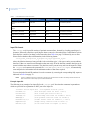
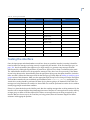
CCTV control systems supported by Picture Perfect
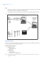
All CCTV control systems can exist in stand-alone, subhost, network host and redundant versions of Picture
Perfect. Once the CCTV control systems are set up and configured, operation of the CCTV control feature will
be a hands-free procedure.
American Dynamics
The interface between the American Dynamics 2150 and Picture Perfect provides the capability to
automatically control CCTV cameras.
Burle Allegiant
Models TC8500 to TC8901 are supported. For controllers providing video loss monitoring and reporting using
the controller printer port, an optional video loss interface component of Picture Perfect can be configured to
issue alarms using the Alarm Monitor screen whenever a camera video signal has been lost.
Burle Allplex
Currently, only model TC8298B is supported. This interface supports up to ten Burle Allplex TC8298B
controllers on a Picture Perfect host computer.
Grundig
The interface between the Grundig Matrix VAZ300 controller and Picture Perfect provides the capability to
automatically control CCTV cameras.
Javelin
The interface between the Javelin Model JO326HI communication arbitrator and Picture Perfect is bidirectional and provides the capability to automatically control CCTV cameras as well as monitor camera
video or sync loss.
Kalatel (also known as GE analog video)
The interface between the Kalatel KTD-312 Computer Interface Unit and Picture Perfect provides the
capability to automatically control CCTV cameras. The full KTD-312 Computer Interface Unit command set is
available to the interface, providing support for camera position and zoom operations.
MAXPRO
The interface between the MAXPRO RD-AT100 MAX1000 controller and Picture Perfect provides the
capability to automatically control CCTV cameras.
3
4
Picture Perfect 4.5 Interface
User Manual
Panasonic Proteus
The interface between the Panasonic Proteus Model 500 controller and Picture Perfect provides the capability
to automatically control CCTV cameras. The Picture Perfect system will communicate with a bridge PC
running a Windows program called PFW (Proteus For Windows).
Panasonic 550
The interface between Panasonic 550 WJ-SX550A controller and Picture Perfect provides the capability to
automatically control CCTV cameras.
Pelco
The interface between the Pelco CM9750 CCTV switcher and Picture Perfect provides the capability to
automatically control CCTV cameras.
Vicon Viper
The interface between a Viper VPS13xx (VPS1300 or VPS1344) controller and Picture Perfect provides the
capability to automatically control CCTV cameras.
Chapter 1
Interface overview
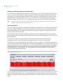
Firepanel systems supported by Picture Perfect
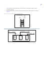
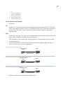
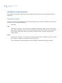
All firepanel systems can exist in a Picture Perfect stand-alone, redundant (two Picture Perfect hosts have
connectivity to a single system receiver port by means of a splitter), or enterprise environment, which generate
Picture Perfect alarms when an alarm is tripped or reset. Communication is uni-directional using a serial line
connection, meaning the Picture Perfect interface only receives data from the interface, and does not send data
back.
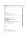
EST
The EST interface to Picture Perfect acts as a secondary monitoring system for the EST panel and recognizes
only the predefined message types built into the interface and set up through Picture Perfect. It acts as a filter
that recognizes predefined alarm conditions coming in over the serial line. Once an alarm is detected, the EST
interface picks up a unique panel/device ID contained within one of the message lines from the serial port. This
unique panel/device ID must have been previously been set up in Picture Perfect. If the panel/device ID was
found along with the alarm, an alarm message is sent to be processed by Picture Perfect. Further information
should be obtained from the primary monitoring device which is the EST panel.
Firesine
The Firesine System interface to Picture Perfect acts as a secondary monitoring system for the Firesine System
and recognizes only the predefined message types built into the interface and set up through Picture Perfect. It
acts as a filter that recognizes predefined alarm conditions coming in over the serial line. Once an alarm is
detected, the Firesine interface extracts the ID for the specific type of message - F<id> (Fire), A<id> (Alert/
Pre-Alarm), D<id> (Fault Detected), R (system reset message - we use the configured message from the
firesine configuration file). The ID or reset message must have been previously set up in Picture Perfect. If
it was, the associated alarm/reset is generated. Time/Date, Zonal, and General Fault messages are ignored.
Further information should be obtained from the primary monitoring device, that is the Firesine panel.
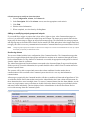
Notifier
This interface acts as a secondary monitoring system for the Notifier AFP400, AFP1010, and AM2020
firepanel and recognizes only the predefined messages built into the interface and set up through Picture
Perfect. It may be used to monitor messages from the Notifier panel. For detector and module monitoring, the
information displayed in the Alarm Monitor will show the device type, status, loop and detector/module
number and a user defined description field. Further message information should be obtained from the primary
monitoring device which is the Notifier panel and associated printer. This interface can monitor system type
messages coming from the Notifier panel which do not have an associated device type.
Simplex
The Simplex interface to Picture Perfect acts as a secondary monitoring system for the Simplex 4100 fire alarm
system, and only recognizes the specific fire, and life-safety alarms and resets the interface was developed to
handle.
5
6
Picture Perfect 4.5 Interface
User Manual
Intrusion detection systems supported by Picture Perfect
The intrusion detection interface for Picture Perfect receives alarm input from the intrusion system and
recognizes predefined message types built into the interface that are set up through Picture Perfect. These
messages are mapped to the Picture Perfect database enabling annunciation of the intrusion event.
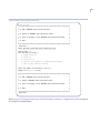
DMP SCS
The DMP SCS-1 interface to Picture Perfect acts as a secondary monitoring system for the DMP SCS-1 alarm
central receiver and recognizes predefined message types built into the interface and set up through Picture
Perfect. Messages or alarms recognized by the DMP SCS-1 interface are looked up in the Picture Perfect
database. For messages NOT in the Picture Perfect database, a dynamic entry will be created in the input group
and alarm database tables. This system can exist in a stand-alone, redundant, or enterprise environment.
Universal Intrusion
The Universal Intrusion interface acts as a secondary monitoring system for external devices that send data in a
specific configurable format to the interface. It is a serial line interface, designed to annunciate alarms and their
resets that have been entered into the Picture Perfect database, to the Picture Perfect Alarm Monitor. This
interface supports operations in a stand-alone, redundant, or enterprise environment.
Chapter 1
Interface overview
Intercom systems supported by Picture Perfect
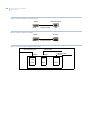
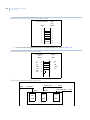
The Picture Perfect intercom interfaces can exist in stand-alone, redundant (two Picture Perfect hosts have
connectivity to a single intercom system port by means of a splitter), and enterprise environments. An instance
of an intercom interface has a one-to-one correspondence between Picture Perfect and the serial line port
connecting it to the intercom hardware. The interface will generate alarms when user configurable message
traffic control messages are received. Communication is uni-directional (unless otherwise indicated) using a
serial line connection, meaning the Picture Perfect interface only receives data from the interface, and does not
send anything back.
AlphaCom
The interface between the Stentofon AlphaCom Exchange and Picture Perfect, provides the capability to
automatically generate AlphaCom alarms in response to Picture Perfect alarms, for Picture Perfect alarms that
have been mapped to the AlphaCom alarms. The AlphaCom Exchange alarm will initiate an action, such as a
pre-recorded audio message. The interface between the Stentofon Alphacom Exchange and Picture Perfect is
bi-directional, with the option to configure the AlphaCom interface to resend messages if communication is
lost.
Commend
The Commend interface to Picture Perfect acts as a secondary monitoring system for the Commend Intercom
System, and recognizes only the pre-defined intercom message types built into the interface, and set up through
Picture Perfect. The data transfer is uni-directional from the Commend Intercom System to the interface on the
Picture Perfect host, across a serial line connection, with XON/XOFF enabled. ACK/NAKs will also be
transmitted between the systems. No handshaking is required for the interface.
Stentofon/Stentofon_MCH
The Stentofon interface to Picture Perfect acts as a secondary monitoring system for the Stentofon Touchline
Intercom System Exchange Models 52/8 and 120/12, and recognizes only the predefined intercom messages
built into the interface and set up through Picture Perfect. The data transfer is uni-directional from the
Stentofon Intercom System to the interface on the Picture Perfect host, across a serial line connection. An
additional Stentofon interface (the Stentofon_MCH), that is designed to support Stentofon Intercom systems
with multiple call handlers (a firmware enhancement), and to provide paging station monitoring on an
individual call handler basis.
Stentofon 9600
The Stentofon 9600 interface to Picture Perfect acts as a secondary monitoring system for the Stentofon P-9600
intercom system and recognizes only the predefined intercom message types built into the interface and set up
through Picture Perfect. The data transfer is uni-directional from the Stentofon P-9600 intercom system to the
interface on the Picture Perfect host, across a serial line connection.
7
8
Picture Perfect 4.5 Interface
User Manual
Miscellaneous systems supported by Picture Perfect
These systems can exist in stand-alone, subhost, network host and redundant versions of Picture Perfect as
noted.
Central Station
This interface provides a communication mechanism between Picture Perfect and central monitoring systems
that allow control of activities for multiple systems and both local and remote sites from a single location. The
central station software can process alarms from the Picture Perfect system. This allows a Central Station
operator to work from one screen and process alarms from both the Picture Perfect Access Control System and
from their intrusion detection system. The communication is two way using a serial line connection and is
available for stand-alone systems.
Siebe CBAS
The Siebe Environmental Control’s Facility Integrator (CBAS) interface to Picture Perfect acts as a secondary
monitoring system for the Facility Integrator and recognizes only “alarm” and “dismissed” message types sent
from the Facility Integrator. All other messages are ignored. The Facility Integrator computer is a PC-based
platform. Communication with the Picture Perfect host is using a serial line connection using the PC’s serial
port. The communication is unidirectional, meaning the interface only receives data from the Facility
Integrator and does not send anything back. This interface is available for standalone or redundant systems.
Remote Alarm Notification
The Picture Perfect Remote Alarm Notification (RAN) package, enables alarms from the Picture Perfect
system to be routed to a remote (non-Picture Perfect) system. The alarms can then be processed by and
responded to, from the remote system. Both systems use the TCP/IP protocol to communicate with each other.
This method of communication guarantees accurate transmission of all data and instant notification of a system
that is no longer connected to the network. The RAN interface is available for standalone, enterprise, or
redundant systems.
OH Receiver
The OH Receiver interface to Picture Perfect acts as a secondary monitoring system for the NX-8E, Ademco,
or Radionix panel and recognizes predefined message types built into the interface and set up through Picture
Perfect. The data transfer is uni-directional from the OH Receiver System (Network or Dial-up) to the interface
on the Picture Perfect host, across a serial line connection. The OH Receiver interface is available for
standalone, enterprise, or redundant systems.
Chapter 2 Installing and removing
This chapter provides information on installing or removing Picture Perfect
interfaces on a standalone, enterpries, or a redundant system.
In this chapter:
Overview . . . . . . . . . . . . . . . . . . . . . . . . . . . . . . . . . . . . . . . . . . . . . . . . . 12
Defining a port . . . . . . . . . . . . . . . . . . . . . . . . . . . . . . . . . . . . . . . . . . . . 13
Installing Picture Perfect base software . . . . . . . . . . . . . . . . . . . . . . . . . 15
Installing on a Redundant system . . . . . . . . . . . . . . . . . . . . . . . . . . . . . . 15
Installing the interface software . . . . . . . . . . . . . . . . . . . . . . . . . . . . . . . 16
Verifying the installation. . . . . . . . . . . . . . . . . . . . . . . . . . . . . . . . . . . . . 23
Removal . . . . . . . . . . . . . . . . . . . . . . . . . . . . . . . . . . . . . . . . . . . . . . . . . 24
10
Picture Perfect 4.5 Interface
User Manual
Overview
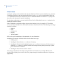
An interface package can be installed at the same time the Picture Perfect system is installed or any time later.
If installing an interface at the same time that the Picture Perfect base system is being installed, follow the
base installation instructions in the Picture Perfect 4.5 Installation Manual to install the base package and
then refer to this document for interface installation.
For redundant configurations, you must install the Picture Perfect Redundant System (pprs) package before
installing the interface software.
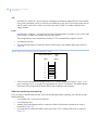
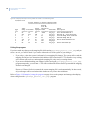
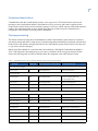
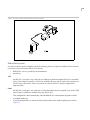
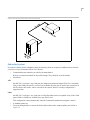
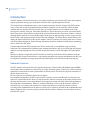
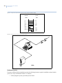
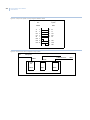
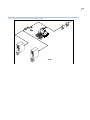
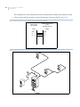
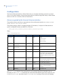
Prior to installation, you should configure the port on the interface device (for example: CCTV switcher,
receiver panel) by which the device will send/receive data to/from Picture Perfect. The following port settings
should be configured:
•
•
•
•
•
Baud rate
Parity
Character size
Stop bits
Xon/xoff control
Refer to the specific manufacturer’s documentation for more information.
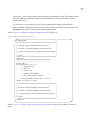
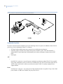
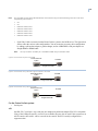
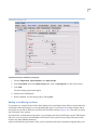
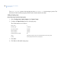
Installation of an interface for Picture Perfect involves these basic steps:
1. Defining a port.
2. Installing the Picture Perfect base software, if necessary.
3. Installing the Picture Perfect Redundant System (pprs) software, if necessary. If it is necessary to
install the pprs software, it should be installed and configured on the primary and backup systems
prior to the interface installation.
4. Installing the Picture Perfect interface software.
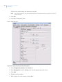
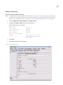
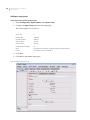
These steps are described in this chapter, using a Kalatel CCTV interface as an example. Because each
interface differs slightly, please observe the screen prompts during the installation and answer the questions
appropriately.
Chapter 2
Installing and removing
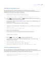
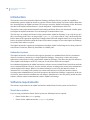
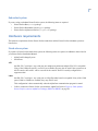
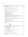
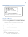
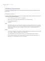
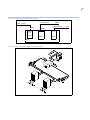
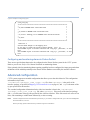
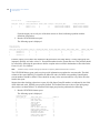
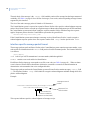
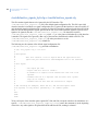
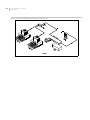
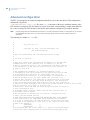
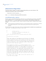
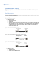
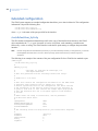
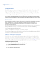
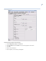
Defining a port
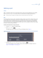
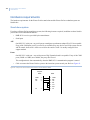
Linux
When you install the software driver for the Digi board, the serial ports will automatically become available.
Refer to your Picture Perfect 4.5 Installation Manual for information about adding Digi board drivers.
Note:
Once the serial port is available, do not define the port in the Picture Perfect Devices, Ports window.
AIX
The Picture Perfect serial ports used to communicate with the interface system will be configured and reserved
using the IBM AIX System Management Interface Tool (SMIT) utility from the system console. In addition,
the serial port baud rate, connection, and physical location of the port are configured using the SMIT utility.
Once the serial port has been configured using the SMIT utility, it will be recognized by Picture Perfect during
the interface software package installation.
Follow the directions below to configure the ports:
1. Log in as root and open a terminal window.
2. Type: smit maktty
Enter
The SMIT utility will load and a list of TTY types will display. Refer to Figure 1.
Figure 1. TTY type screen
3. Select the TTY: tty rs232 Asynchronous Terminal
Enter
A list of parent adapters for each available serial port will be displayed. An example is shown in
Figure 2: Parent adapter screen on page 12.
11
12
Picture Perfect 4.5 Interface
User Manual
Figure 2. Parent adapter screen
4. Determine where the interface line will be connected to the RISC System/6000. At least one of the two
standard serial ports is used by the support modem (sa1). The other standard serial port (sa0) is used by
the console, if it is an ASCII terminal. If a graphical console is present, one of the serial ports may also
be used for the interface, if available.
The interface line will be connected to a multiport adapter, which must be installed and connected to
the RISC System/6000 in order to appear on this list. Since your system may have one or more
multiport adapters (sa2, sa3, sa4, etc.), select the one you will be using for this communication line.
5. Select the parent adapter and press
Enter
. Figure 3 displays next.
Figure 3. Add a TTY screen
6. Move the cursor to the PORT Number field.
a. Press F4 to display the list of ports. The ports are numbered sequentially and should be labeled on
the RS-232 connector.
b. Highlight the port to which the interface line will be connected.
c. Press
Enter
and the port you selected should be displayed in the PORT Number field.
Chapter 2
Installing and removing
7. Verify the parameters have the values you configured on the interface device’s port, for example:
•
•
•
•
•
BAUD rate
PARITY
BITS per character
Number of STOP BITS
XON-XOFF (FLOW CONTROL)
1200
none
8
1
none
If the parameters are not correct, move the cursor by using the up and down arrow keys and change the
entry by typing over the existing value.
8. Move to the field STTY attributes for RUN time.
a. Delete the default entry.
b. Replace with: cread,clocal
c. Press
Enter
.
9. Move to the field STTY attributes for LOGIN.
a. Delete the default entry.
b. Replace with: cread,clocal
c. Press
Enter
.
d. Note the tty number assigned.
10. If multiple interfaces will be configured, or you intend to use video loss monitoring and alarm
reporting capability, repeat step 6 through step 9 as necessary for the additional ports.
11. Press
F10
to exit the SMIT utility and complete the procedure.
Installing Picture Perfect base software
If you have not yet installed the Picture Perfect base software, refer to the Picture Perfect 4.5 Installation
Manual for information about installing Picture Perfect base.
If you have previously installed the Picture Perfect base software, continue with the next section.
Installing on a Redundant system
For redundant configurations, you must install the Picture Perfect Redundant System (pprs) package before
installing the interface software.
If you have not yet installed the pprs software, refer to the Picture Perfect 4.5 Redundant Edition User
Manual for more information about installing the pprs package.
If you have previously installed the pprs software, continue with the next section.
13
14
Picture Perfect 4.5 Interface
User Manual
Installing the interface software
Before proceeding with the installation:
•
•
You will need the port name (defined in the section Defining a port on page 11) and the baud rate.
You must stop the Picture Perfect application prior to installation. If running in a redundant
environment, Picture Perfect on the redundant (backup) host must also be stopped prior to package
installation. If Picture Perfect is not stopped, the interface will not start until the next restart of Picture
Perfect.
Follow these steps to install the interface software:
1. Log on as ppadmin and open a terminal window.
2. Type the following to shut down Picture Perfect:
. /cas/bin/profile
rc.pperf -k
Enter
Enter
3. Switch users to root by typing the following command.
su -
Enter
Enter your root password, and then press
Enter
.
4. Insert the Picture Perfect v4.5 Installation DVD into your server. Wait for the DVD ROM LED to stop
blinking before proceeding.
Linux
5. Unmount the DVD by typing the following command:
umount /media/pp45
Enter
6. Mount the DVD by typing the following command:
Linux
mount /dev/dvd /media
Enter
AIX
mount -v cdrfs -r /dev/cd0 /mnt
Enter
7. Change to the root directory by typing cd /
Enter
.
8. To display a list of installation options, type:
Linux
/media/Linux/INSTALL -i
Enter
AIX
/mnt/AIX/INSTALL -i
Enter
You will receive messages similar to those shown below, followed by a list of packages:
Chapter 2
Installing and removing
-----------------------------------------------------------------------------Picture Perfect CD-ROM Installation - 4.5 04/10/09
Copyright (C) 1989-2009 GE Security, Inc.
------------------------------------------------------------------------------
The following Interface product(s) are available:
Prod #
-----0
1
2
3
4
5
6
7
8
9
10
11
12
13
14
15
16
17
18
19
20
21
22
23
24
25
26
27
Name and Descriptions
--------------------allegiant
Burle Allegiant CCTV Interface
allplex
Burle Allplex CCTV Interface
alphacom
Stentofon AlphaCom Intercom Interface
amdyn
American Dynamics CCTV Interface
cbas
Siebe Environmental Control Interface
commend
Commend Intercom Interface
cstation
Central Station Interface
est
EST Fire Alarm Interface
firesine
Firesine Fire Alarm Interface
grundig
Grundig VAZ300 CCTV Interface
javelin
Javelin J0326HI CCTV Interface
kalatel
Kalatel KTD-312 CCTV Interface
maxpro
Maxpro MAX1000 CCTV Interface
notifier
Notifier Fire Alarm Interface
oh_receiver
Osbourne-Hoffman Receiver Interface
panasonic
Panasonic Proteus 500 PFW Interface
panasonic550 Panasonic WJ-SX550A Interface
panasonic650 Panasonic WJ-SX650A Interface
pelco
Pelco CM9750 CCTV Interface
pelcob
New Pelco CM9750 CCTV Interface
ran
Remote Alarm Notification System
scs
DMP SCS-1 Alarm Interface
simplex
Simplex System Interface
stentofon
Stentofon TouchLine Intercom Interface
stentofon9600 Stentofon P-9600 Intercom Interface
stentofon_mch Stentofon Multiple Call Handler Intercom Interface
univ_intr
Universal Intrusion Interface
viper
Vicon Viper VPS13xx Interface
Enter product number(s), separated by ',' to select, 'q'
to quit:
9. Type the corresponding product number, for example 11, to install the Kalatel KTD-312 CCTV
Interface (kalatel) package and press Enter .
You will be asked to confirm your choice.
You have selected the following product(s):
11
kalatel
Kalatel KTD-312 CCTV Interface
15
16
Picture Perfect 4.5 Interface
User Manual
Is this correct (y/n)? [y]
10. To confirm, type: y
Enter
.
You will be asked to confirm the installation.
Installing kalatel...
Picture Perfect Multi-package Installation - 4.5 04/10/09
Copyright (C) 1989-2009 GE Security, Inc.
Installing from image in /media/Linux/pp ...
Do you want to install the Picture Perfect KALATEL Package (y/n)? [y]
11. To confirm, type: y
Enter
.
Messages similar to the following will display:
Picture Perfect NLS Text Save - 4.5 01/16/06
Copyright (C) 2000-2006 GE Security
Tue Sep 15 08:43:57 EDT 2009
This package has no nls or help files to save...
-----------------------------------------------------------------------------Picture Perfect KALATEL Package Installation - Version 4.5 04/10/09
Copyright (C) 1989-2009 GE Security, Inc.
-----------------------------------------------------------------------------Installing this package will configure this server to interface
to KALATEL CCTV system.
Starting the Informix database.. Done
Configuring ports
This section describes how to configure the ports and identify the baud rate. The instructions are listed below.
During the installation, the following message displays:
Digiboard/port expander check...
The Kalatel Interface requires the use of a serial port.
Do you have a digiboard or port expander attached to the host (y/n)? [y] n
1. Press Enter or y Enter to indicate that you have a Digiboard or port expander; or press n
indicate no Digiboard or port expander is attached.
Enter
to
If you entered n, the following message displays:
NOTE: The installation of this interface REQUIRES the usage of a port to continue.
Do you wish to use the comm ports (y/n)? [y]
Chapter 2
Installing and removing
2. Press Enter or y
comm ports.
Enter
to use the comm ports; or press n
Enter
to indicate that you will not use the
The installation program will verify if there are ports available on the system. If there are no ports
available, a message will display and you will exit the installation program.
If the check finds a port, the installation will proceed. Messages similar to the following displays:
Verifying if serial ports are available for the KALATEL Interface... OK.
Loading KALATEL CCTV Server Package...
Extracting files...from media
The files have been read from the media.
Please select a tty port:
3. Select the port to be used for the interface server package from the list provided.
A message similar to the following displays:
You must select a tty port for the KALATEL interface.
The following tty ports are available:
Linux
A list similar to the following displays:
/dev/ttyS1
/dev/ttyS2
/dev/ttyS3
AIX
For RS/6000: The port name created previously using the SMIT utility appears in a list similar to the
following:
/dev/tty10
/dev/tty11
/dev/tty12
The following prompt displays:
Please select a tty port:
17
18
Picture Perfect 4.5 Interface
User Manual
4. Enter a port from the list exactly as it appears, for example:
Linux
For Linux: /dev/ttyS2
Enter
AIX
For RS/6000: /dev/tty10
Enter
If you entered a valid tty port from the list, the following message will appear:
Please enter the baud rate for the selected port
(1200, 2400, 4800, 9600, 19200): [1200]
If you entered a tty port that is not in the list displayed, you will be asked to re-enter the tty port.
5. Enter the baud rate of the interface console port.
The selected baud displays and you will be asked to confirm the setting.
Selected baud rate is: 9600
Is this baud rate correct (y/n)? [y]
6. Press
Enter
or y
Enter
to accept; or press n
Enter
to change the number.
If you selected n, you will be asked to re-enter the baud rate.
If you selected y, messages similar to the following will appear:
Setting default Monitor Id to 00
Setting Alarm On function code to '['
Setting Alarm Off function code to '\'
Creating Kalatel Command Strings Table
/cas/db/text/kalatel_command_strings.table
Creating Kalatel cctv map file /cas/db/text/ktd.map
Installing CCTV SQL
Loaded report 'CCTV
Loaded report 'CCTV
Loaded report 'CCTV
Loaded report 'CCTV
Loaded report 'CCTV
Loaded report 'CCTV
Loaded report 'CCTV
Loaded report 'CCTV
Loaded report 'CCTV
Reports...
Alarms'.
Areas'.
Doors'.
Hosts'.
Inputs'.
Micros CommFailure'.
Micros Overflow'.
Micros ReaderFailure'.
Readers'.
Chapter 2
Installing and removing
Installing on a Redundant system
This section describes how to configure a redundant system. The instructions are listed below.
Informational messages followed by a question display to give you the option of installing the interface on a
redundant host. The messages will be similar to the following:
Updating Picture Perfect backup configuration...
Picture Perfect backup configuration update completed
Is this interface to run in a redundant Picture Perfect environment (y/n)? [n]
1. Press y Enter to accept the default setting or n
run in a redundant Picture Perfect environment.
Enter
depending on whether or not the interface is to
If you selected n, skip to Configuring additional interfaces on page 19 as the installation process for
this interface is complete.
If you selected y, a message similar to the following will appear:
Installation
’primary1’-primary host
Please enter
MUST be performed on the primary host. It is assumed that this host -is the primary host. The redundant host name must be different from the
name.
the name of the redundant host:
2. Enter the name of the redundant host.
The host name you specified will be displayed and you will be asked to confirm it.
Redundant host is: backup1
Is this correct (y/n)? [y]
3. Enter y
Enter
to accept; or press n
Enter
to change the redundant host name.
If you selected n, you will be asked to re-enter the redundant host name. If you selected y, the
following messages will appear:
Checking to verify ‘backup1’ is reachable...
Updating redundant Picture Perfect backup configuration...
Picture Perfect backup configuration update completed
Reflecting the KALATEL.INST installation onto the redundant host backup1...
Configuring additional interfaces
This section describes how to configure additional interface devices. The instructions are listed below.
The installation of the current copy of the interface is complete, as indicated, and you will be asked if you want
to install another copy of the interface. The messages will be similar to the following:
The ktd_tty2 installation has completed successfully. Do you wish to configure
another Kalatel CCTV Device
(y/n)? [n]
19
20
Picture Perfect 4.5 Interface
User Manual
1. Enter y to configure another interface device, or n (the default value) to complete the installation
process.
If you entered y, you will return to step 3 in the section Configuring ports on page 16. Some of the
steps will be omitted; for example, you will not be asked if this is a redundant configuration as, either
all of the interfaces are running in a redundant environment, or none of the interfaces are redundant.
If you entered n, you will receive messages similar to the following as the installation process
completes:
The 'KALATEL.INST' installation has completed successfully.
Checking if need to update nls files...
Picture Perfect NLS Check - 4.5 04/10/09
Copyright (C) 2000-2009 GE Security, Inc.
Tue Sep 15 09:08:17 EDT 2009
No nls files for kalatel package
Running /cas/bin/fixperm on /tmp/kalatel.perm file...
No errors detected
/cas/bin/fixperm finished.
inst_pkgs: Running /cas/bin/interfaces.perm.sh on package kalatel...
Installing desired Interface product(s) was successful.
The Installation has completed.
The system needs to be rebooted for the changes to take effect.
Reboot the system (y/n)? [y]
2. Press
CAUTION:
Enter
to reboot the system.
If the interface package was running in a redundant Picture Perfect environment, then you MUST
synchronize the database on the backup host with the primary host by performing “Database Recovery” on
the backup host prior to starting redundant Picture Perfect on the backup host. Refer to the Picture Perfect
4.5 Redundant Edition User Manual for details.
Chapter 2
Installing and removing
Verifying the installation
This section describes how to verify the installation process. The instructions are listed below.
1. When the system is back up, log in as root and verify that the interface is running by typing at the #
prompt:
ps -ef | grep msan
Enter
You should get output similar to the following:
root 12579 17148 0 10:19:36 pts/0 0:00 msan
2. For further verification, type at the # prompt:
ps -ef | grep ktd_
Enter
The output should be similar to the following:
root 16164 17148 0 10:19:36 pts/0 0:00 ktd_tty2
root 16169 17148 0 10:19:37 pts/00:00 ktd_tty3
The second output line will only appear if more than one device was configured.
If you have performed a redundant installation, you must perform “Database Recovery” on the backup host
prior to starting redundant Picture Perfect on the backup host. Refer to the Picture Perfect 4.5 Redundant
Edition User Manual for details.
21
22
Picture Perfect 4.5 Interface
User Manual
Removal
The removal script will automatically detect whether or not you are running in a redundant Picture Perfect
environment. If you are running in a redundant environment, additional messages will appear during the
removal process.
Note:
Picture Perfect must be stopped prior to package removal. If running in a redundant Picture Perfect environment,
Picture Perfect on the redundant host must also be stopped prior to package removal.
Follow these steps to remove the Picture Perfect Interface Server package:
1. Log in to the system as root and open a terminal window.
2. Type: cd /
Enter
3. Start the removal program by typing: ppr
Enter
Messages similar to the following will appear on the screen:
Picture Perfect Package Removal-/custom-pp/bin/ppr 2.0 02/12/03 Copyright (C) 19922003 GE Interlogix, Inc.
WARNING: THIS PROGRAM WILL COMPLETELY REMOVE PICTURE PERFECT PACKAGES AND ANY
DATABASES USED BY THE PACKAGE. SELECTING base OR all WILL REMOVE PICTURE PERFECT
ENTIRELY
ARE YOU SURE YOU WANT TO PROCEED?
(Type 'yes' and press the <Enter> key to proceed)
4. To continue, type: yes
Enter
If you entered yes, a list of the Picture Perfect packages currently installed will be displayed. You will
then be asked which package you would like to delete. For example:
The following Picture Perfect packages are currently installed:
base
graph
image
impexp
kalatel
Enter the name of the package to remove:
5. Type the name of the package you are removing, for example:
kalatel Enter
Messages similar to the following will be displayed:
Removing the kalatel package.
Picture Perfect Kalatel interface package removal - Version 1.2. 7/6/02.
Removing 'tty2' entry for Kalatel interface from the port database table...
Updating Picture Perfect backup configuration...
The Kalatel CCTV Interface package has been completely removed from the system.
Exiting...
Chapter 2
Installing and removing
The removal process has completed. Program Exiting.
The system needs to be rebooted for the changes to take effect.
Reboot the system (y/n)? [y]
6. Enter y (the default value) to reboot the system, or type n if you do not want to reboot at this time.
Redundant systems
If the interface package was running in a redundant Picture Perfect environment, then you will also see
messages similar to the following:
Redundant kalatel interface configuration detected:
This host:
primary1
Other host:
backup1
Redundant kalatel operation is ENABLED.
Map file changes will be reflected on the other host.
Updating Picture Perfect backup configuration...
Removing entry for Kalatel interface from the port database table
Removing redundant Kalatel interface installation from the remote system
‘backup1’...
The Kalatel CCTV Interface package has been successfully removed.
The system needs to be rebooted for the changes to take effect.
Reboot the system (y/n)? [y]
7. Enter y (the default value) to reboot the system, or press n if you do not want to reboot at this time.
CAUTION:
If the interface package was running in a redundant Picture Perfect environment, then you MUST
synchronize the database on the backup host with the primary host by performing “Database Recovery” on
the backup host prior to starting redundant Picture Perfect on the backup host. Refer to the Picture Perfect
4.5 Redundant Edition User Manual for details.
23
24
Picture Perfect 4.5 Interface
User Manual
Appendix A Configuring an AlphaCom
interface
This appendix provides information on configuring the interface between the
Stentofon AlphaCom Exchange and Picture Perfect, which provides the capability
to automatically generate AlphaCom alarms in response to Picture Perfect alarms.
In this appendix:
Introduction. . . . . . . . . . . . . . . . . . . . . . . . . . . . . . . . . . . . . . . . . . . . . . . 26
Software requirements. . . . . . . . . . . . . . . . . . . . . . . . . . . . . . . . . . . . . . . 26
Hardware requirements . . . . . . . . . . . . . . . . . . . . . . . . . . . . . . . . . . . . . 27
Configuration . . . . . . . . . . . . . . . . . . . . . . . . . . . . . . . . . . . . . . . . . . . . . 31
Advanced configuration . . . . . . . . . . . . . . . . . . . . . . . . . . . . . . . . . . . . . 41
Interface data file backup and restore . . . . . . . . . . . . . . . . . . . . . . . . . . 46
26
Picture Perfect 4.5 Interface
User Manual
Introduction
The interface between the Stentofon AlphaCom Exchange and Picture Perfect, provides the capability to
automatically generate AlphaCom alarms in response to Picture Perfect alarms, for Picture Perfect alarms that
have been mapped to the AlphaCom alarms. The messages sent to the AlphaCom Exchange, follow the format
described in the AlphaCom Data Protocol - System Integration - Implementation 1999-09-30.
The interface between the Stentofon AlphaCom Exchange and Picture Perfect is bi-directional, with the option
to configure the AlphaCom interface to resend messages if communication is lost.
The first step is to configure the Picture Perfect system and the AlphaCom Exchange, or to verify the set up if
this is an existing system. Next, use the provided alphacom_map script to link or “map” the desired Picture
Perfect alarms to the appropriate AlphaCom Exchange alarms. When the mapped alarm is received by Picture
Perfect, the AlphaCom alarm to which the Picture Perfect alarm is mapped, is sent to the AlphaCom Exchange.
No operator intervention is required.
The AlphaCom interface supports the configuration of multiple AlphaCom Exchange devices being connected
to the Picture Perfect host, limited by the number of available ports.
Redundant systems
The AlphaCom interface to Picture Perfect supports operations in a redundant Picture Perfect environment
where two hosts have connectivity to a single AlphaCom Exchange. Connectivity is achieved by using a
splitter between the Picture Perfect system and the AlphaCom Exchange. This allows the physical connection
of the AlphaCom Exchange to an RS-232 serial port on each Picture Perfect host computer.
In a redundant configuration, the AlphaCom interface software executes on both Picture Perfect hosts and both
receive alarm notifications. However, only the interface software executing on the primary host communicates
with the AlphaCom Exchange. Whenever an alarm notification is received by the interface software, it
determines if it is executing on the primary host. Alarm notifications received by the interface software
executing on the redundant host are processed but output to the AlphaCom Exchange is suppressed. In the case
of a failover, the mode on the redundant host will change to indicate that it is now the primary and the interface
software will then conduct communications with the AlphaCom Exchange.
Software requirements
The software requirements for the AlphaCom interface and the Picture Perfect system are listed below.
Stand-alone system
If you are using a stand-alone Picture Perfect system, the following items are required:
•
•
Picture Perfect Base ( base) package
Picture Perfect Alphacom interface ( alphacom) package
27
Redundant system
If you are using a redundant Picture Perfect system, the following items are required:
•
•
•
Picture Perfect Base ( base) package
Picture Perfect Redundant System (pprs) package
Picture Perfect Alphacom interface ( alphacom) package
Hardware requirements
The hardware requirements for the Picture Perfect stand-alone and the Picture Perfect redundant system are
listed below.
Stand-alone system
If you have a Picture Perfect stand-alone system, the following items are required, in addition to those listed in
your Picture Perfect Installation Manual:
•
•
AlphaCom Exchange System
Serial Ports
AIX
One RS-232-C serial port - any serial port on a multiport asynchronous adapter EIA-232 is acceptable.
If any of the COM ports (serial 1 or serial 2) are available, they may also be used. If the system uses an
ASCII console, then serial 1 will be reserved for the console. Serial 2 is usually configured for a
support modem.
Linux
One RS-232-C serial port - any serial port on a Digi Expander board is acceptable. If any of the COM
ports (COM1 or COM2) are available, they may also be used.
This configuration is done automatically when the AlphaCom communication program is started.
•
Cable to connect the Picture Perfect system and the AlphaCom. Refer to Figure 4, Cable pinouts:
Picture Perfect system to AlphaCom exchange (DB25F to DB25F) on page 28.
28
Picture Perfect 4.5 Interface
User Manual
Figure 4. Cable pinouts: Picture Perfect system to AlphaCom exchange (DB25F to DB25F)
Picture Perfect Host
Computer
DB25F
AlphaCom
Receiver
DB25F
Shield
1
1
Shield
Rxd
2
2
Rxd
Txd
3
3
Txd
4
RTS
5
CTS
8
DCD
7
SG
SG
7
Figure 5. Overview of the Picture Perfect and Intercom interface
Redundant system
If you have a Picture Perfect redundant system, the following items are required, in addition to those listed in
your Picture Perfect Redundant Edition User Manual:
•
•
AlphaCom Exchange System
Serial Ports
29
AIX
One RS-232-C serial port - any serial port on a multiport asynchronous adapter EIA-232 is acceptable.
If any of the COM ports (serial 1 or serial 2) are available, they may also be used. If the system uses an
ASCII console, then serial 1 will be reserved for the console. Serial 2 is usually configured for a
support modem.
Linux
One RS-232-C serial port - any serial port on a Digi Expander board is acceptable. If any of the COM
ports (COM1 or COM2) are available, they may also be used.
This configuration is done automatically when the AlphaCom communication program is started.
•
•
A standard splitter box
Two pass-through cables to connect the Picture Perfect hosts to the standard splitter ports. Refer to
Figure 6.
Figure 6. Cable pinouts: Picture Perfect system to splitter (DB25F to DB25M)
Picture Perfect System
DB25F
•
Splitter
Port
DB25M
1
1
2
2
3
3
4
4
5
5
7
7
8
8
20
20
Cable to connect from the splitter master port to the AlphaCom Exchange (See figure below).
Figure 7. Cable pinouts: splitter to AlphaCom Exchange (DB25F to DB25F)
Splitter Master
Port
DB25F
AlphaCom
Receiver
DB25F
Shield
1
1
Shield
Rxd
2
2
Rxd
Txd
3
3
Txd
4
RTS
5
CTS
8
DCD
7
SG
SG
7
30
Picture Perfect 4.5 Interface
User Manual
Figure 8. Overview of the cable configuration using a splitte
DB25F
To AlphaCom Exchange
DB25M
DB25F
To Primary Host
To Redundant Host
DB25M
DB25M
Master
Port
Port 1
Port 2
DB25F
DB25F
DB25F
Splitter
Figure 9. Overview of the redundant Picture Perfect and Intercom interface
DB25F
31
Configuration
The Picture Perfect interface to the AlphaCom system allows alarms that are detected by the Picture Perfect
system to trigger predefined events on the AlphaCom system. Before this can happen, Picture Perfect must be
informed of which alarms should be sent to the Alphacom system and how that Picture Perfect alarm is
mapped to an AlphaCom system alarm number.
Picture Perfect treats alarms as a collection of information, which includes:
•
•
•
Input group
Location
Host number
The AlphaCom system distinguishes alarms by a unique four-digit identifier per alarm location and condition.
Once you have set up the alarms on Picture Perfect, you need to set up the mapping of alarms to the AlphaCom
system. This procedure is accomplished by executing a script which requires operator input.
Note:
The AlphaCom interface uses the Picture Perfect CCTV backend process as it is an output interface. As such, CCTV
reports will be used for determining locations.
For a successful configuration, follow these steps:
1. Defining input groups on page 31.
2. Identifying location types on page 31.
3. Using SQL reports on page 32.
4. Mapping CCTV Monitored Events on page 33.
Defining input groups
In the Picture Perfect system there are many possible sources of alarms. The fundamental concept is that
alarms are triggered through input groups. There are several components of the system that use input groups.
These are Areas, Doors, Readers, Input Points, Micros, Hosts, and Input Groups themselves. All of these
windows allow you to select an input group for the various events that can occur at these locations. Only the
Input Group window has a field to define the alarm associated with this group.
To trigger an AlphaCom event for an input point, you should create an input group for that point only. Then,
you can associate the AlphaCom event to the alarm on that individual input group and, therefore, the point
itself. Boolean input group alarms are not supported in this interface.
Identifying location types
An area is a group of one or more readers and represents a location type. A single area may be assigned to
multiple readers and doors. Areas are similar to input groups, in they group a large number of readers together
to make configuration easier. Unlike input groups, areas cannot contain other areas. This means that whenever
an area event occurs, the unique location of the event (reader) is also reported. This gives you the ability to
specify the exact camera to turn on because you know at what reader the lost badge is being used.
See Table 1 for location types and alarm conditions. Detailed information may be found in the Picture Perfect
User Manual.
32
Picture Perfect 4.5 Interface
User Manual
Table 1.
Where input groups are used
Location type
Alarm condition
Area
Invalid Badge (expired or no category match)
Suspended Badge
Lost Badge
Unknown Badge
Anti-Passback
Duress
Door
Forced Open
Held Open
Pre-alarm
Reader
Valid Badge (exit button tamper only)
Invalid Badge (all badge errors except Unknown)
Input Point
Alarm
Micro
Badge History Overflow
Alarm History Overflow
Upstream Micro Communications Failure
Downstream Micro Communications Failure
Reader Communications Failure
Host
Host-to-Host Communications Failure
Network Database Communications Failure
Using SQL reports
During the installation process, nine SQL reports are installed. The reports are:
CCTV Areas
CCTV Micros ReaderFailure
CCTV Doors
CCTV Readers
CCTV Inputs
CCTV Hosts
CCTV Micros CommFailure
CCTV Alarms
CCTV Micros Overflow
These reports provide you with the information that you will need to know about mapping alarms to the
AlphaCom system. To add or delete an alarm from the CCTV system, you must know the Alarm Id, Input
Group Id, and Location Id.
33
These reports detail the alarm conditions defined within your system and display the required information. The
information includes:
•
•
•
Alarm Id
Input Group Id
Location Id
For example: If you want an alarm to be sent to the AlphaCom system whenever the door with the description
000-1-00 DOOR is forced open, you must first generate a CCTV Doors Report to obtain the required
information.
Generating a SQL Report
Follow these steps to generate a SQL report:
1. From the Reports menu, select the Report menu item, then click the Report tab.
2. From the Select a Report Category list pane, select the category for this report. When you select a
category, the existing reports in that category display in the Select a Report list pane.
3. To open an existing report, select it from the Select a Report list pane, then from the toolbar, click
Run.
4. Click Print to display the Print Preview page. From this window you may Save to pdf or Print to your
local printer.
Mapping CCTV Monitored Events
Use the program alphacom_map to add, delete, and print the alarms that are sent to and received from the
AlphaCom system. The alphacom_map program does not allow you to edit an alarm. To make changes to
an alarm, you must first delete the alarm and then add a new alarm.
If the AlphaCom interface has been configured for a redundant Picture Perfect environment, then the changes
made to the map file are reflected on the redundant host.
Refer to the following sections for more information:
•
•
•
•
•
Adding an alarm on page 34.
Deleting an alarm on page 37.
Changing an alarm on page 38.
Printing the map file on page 38.
Exiting the program on page 40.
To run the alphacom_map program you will need to be logged onto the server as root.
To run the alphacom_map program, type at the command prompt: alphacom_map
Enter
34
Picture Perfect 4.5 Interface
User Manual
Adding an alarm
This section describes how to add a new AlphaCom controlled alarm. Refer to Example of adding an
AlphaCom alarm on page 36 to see the messages and prompts that display when adding an alarm.
Follow these steps to add an AlphaCom alarm:
1. At the Selection prompt, type a to add a new AlphaCom controlled alarm.
A message displays to confirm a new alarm is being added, and you will be prompted for the Input
Group Id of the alarm to be added.
2. Enter the Input Group Id. The Input Group Id can be found on one of the CCTV SQL reports listed
on page 32.
3. Once a valid Input Group Id has been entered, you will be prompted for the associated Alarm Id.
Enter the associated Alarm Id from the same report entry as used for the Input Group Id.
4. Once a valid Alarm Id has been entered, you will be prompted for the associated Location Id. Enter
the associated Location Id from the same report entry as used for the Input Group and Alarm IDs.
5. Once a valid Location Id has been entered, you will be prompted for the Outgoing AlphaCom Alarm
Number, to which the Picture Perfect alarm you have just specified, will be mapped. Enter the number
of the AlphaCom alarm that causes the AlphaCom Exchange device to perform the actions you want
for this event when the Picture Perfect alarm occurs. The range of 1-to-9999 can be used for
AlphaCom alarm numbers.
6. You will now be given the option to enter an associated alarm description for this mapping. The alarm
description is useful when identifying a mapping entry on a report. Enter y to add an alarm
description, or n to omit the description.
•
•
If you select y, you are prompted for the alarm description. The Picture Perfect Alarm description
may be used, although any description that enables the user to identify which alarm it is, may be
used. The description MUST fit on one line. The entry should be as concise as possible, because
when the report is printed, the entries that are larger than the width of the paper will be wrapped to
the next line, and the report may not be readable.
If you select n, the information you have entered displays, and you will be asked to confirm the
entries. Skip to step 8.
7. Enter the Alarm Description. The information you have entered, including the alarm description,
displays and you will be asked to confirm the entries.
8. If the entries are not correct, select n and the mapping options display, that is, you will return to
step 1, where you may perform another selection, or exit the program.
If the entries are correct, select y. If only one AlphaCom node is configured, then you will get a
message informing you that the Outgoing AlphaCom Alarm Number you specified, is mapped to
that AlphaCom node number. The mapping data you have specified will be added to the
alphacom.map file. You will be returned to step 1, where you may make another mapping option
selection.
If multiple AlphaCom nodes were configured, a list will be displayed showing each node number that
was configured, and the name of the port it is on. You will need to enter the node numbers of the
35
AlphaCom devices to which the Outgoing AlphaCom Alarm Number you specified is to be sent
when the Picture Perfect alarm occurs.
9. Enter the Node Numbers. The node numbers you specified will be verified against the ones
configured, and if they are valid, you will be asked to confirm the node number selection that you
made.
10. If the alarm number to node number mappings are correct, select y, and the mapping data you have
specified will be added to the alphacom.map file. You will be returned to step 1, where you may
make another mapping option selection.
If the mapping data is incorrect, select n, and you will return to step 9, where you will once again be
prompted for the node number mappings.
36
Picture Perfect 4.5 Interface
User Manual
Figure 10. Example of adding an AlphaCom alarm
# alphacom_map
*********************************************************
*
*
* A) Add an AlphaCom controlled alarm
*
*
*
* D) Delete an outgoing AlphaCom controlled alarm
*
*
*
* P) Print a hardcopy of all AlphaCom controlled alarms *
*
*
* X) Exit
*
*********************************************************
Selection: a
Adding an outgoing AlphaCom controlled alarm
---------------------------------------Input Group ID (1-999999): 102
Picture Perfect Alarm ID (1-999999): 21
Location ID (1-99999): 45
Outgoing AlphaCom alarm number (1-9999): 15
You may now enter an optional alarm description to identify this mapping entry. For
example, the Picture Perfect alarm description may be used.
Do you wish to enter an alarm description (y/n)? [y] y
The alarm description must fit on one line. Enter the alarm description then hit
<ENTER>: 00-1-00 Door Forced Open
Adding: Picture Perfect input group 102, alarm 21, location 45, Alphacom alarm 15,
Alarm Description: 00-1-00 Door Forced Open
Is this OK (y/n)? [y] y
Adding an alarm to AlphaCom map entry
------------------------------------The following AlphaCom Node Numbers were configured at installation time, for the
specified ports:
Node
Number
Port
---------1
/dev/tty1
2
/dev/tty4
10
/dev/tty2
20
/dev/tty3
Enter the AlphaCom Node Numbers from the above list, for which alarm '15' will be
mapped. The Node Numbers should be separated by a space or tab.
Node numbers: 1 10
You have specified to map:
Outgoing AlphaCom Alarm Number .. : 15
to
AlphaCom Nodes .................. : 1 10
Is this correct (y/n)? [y]
*********************************************************
*
*
* A) Add an ALPHACOM controlled alarm
*
*
*
* D) Delete an ALPHACOM controlled alarm
*
*
*
* P) Print a hardcopy of all controlled alarms
*
*
*
* X) Exit
*
*********************************************************
37
Deleting an alarm
This section describes how to delete an existing AlphaCom Exchange controlled alarm. Refer to Figure 11,
Example of deleting an AlphaCom alarm on page 38 to see the messages and prompts that display when
deleting an alarm.
When you delete an alarm from the mapping file, the Picture Perfect alarm no longer triggers the AlphaCom
event.
Note:
When the mapped AlphaCom alarm is deleted, the mappings for all of the AlphaCom nodes to which an AlphaCom
alarm is sent, are also removed.
It is recommended that prior to beginning the deletion process, you follow the instructions for printing the map file, as
explained in the section Printing the map file on page 38. This way you will have the Picture Perfect Alarm, Input Group,
and Location Id, as well as the outgoing AlphaCom alarm number of the alarm you want to delete, handy.
Follow these steps to delete an AlphaCom alarm:
1. At the Selection prompt, type d to delete an AlphaCom controlled alarm.
A message displays to confirm an alarm is being deleted, and you will be prompted for the Input
Group Id of the alarm to be deleted.
2. Enter the Input Group Id of the alarm to be deleted.
3. Once a valid Input Group Id has been entered, you will be prompted for the associated Alarm Id.
Enter the associated Alarm Id.
4. Once a valid Alarm Id has been entered, you will be prompted for the associated Location Id. Enter
the associated Location Id.
5. Once a valid Location Id has been entered, you will be prompted for the Outgoing AlphaCom Alarm
Number, to which the Picture Perfect alarm you have just specified, is mapped. Enter the number of
the AlphaCom alarm.
The mapping file is checked to see if there are any lines that match the information entered.
If there are no lines, the message No Matching Lines Found displays, and you are returned to
the Selection prompt, where you may choose another mapping option to perform.
If a matching line is found, you are asked to confirm the deletion.
6. If the entries are correct, select y and all matching lines in the mapping files are removed, and you
are returned to the Selection prompt, where you may choose another mapping option to perform.
If you select n, the mapping files are not altered, and you are returned to the Selection prompt, where
you may choose another mapping option to perform.
38
Picture Perfect 4.5 Interface
User Manual
Figure 11. Example of deleting an AlphaCom alarm
# alphacom_map
*********************************************************
*
*
* A) Add an outgoing AlphaCom controlled alarm
*
*
*
* D) Delete an outgoing AlphaCom controlled alarm
*
*
*
* P) Print a hardcopy of all AlphaCom controlled alarms *
*
*
* X) Exit
*
*********************************************************
Selection: d
Deleting an outgoing AlphaCom controlled alarm
-----------------------------------------Input Group ID (1-999999): 102
Picture Perfect Alarm ID (1-999999): 21
Location ID (1-999999): 45
Outgoing AlphaCom alarm number (1-9999): 15
Are you sure (yn)? [y]
*********************************************************
*
*
* A) Add an outgoing AlphaCom controlled alarm
*
*
*
* D) Delete an outgoing AlphaCom controlled alarm
*
*
*
* P) Print a hardcopy of all AlphaCom controlled alarms *
*
*
* X) Exit
*
*********************************************************
Changing an alarm
The alphacom_map program does not permit editing an entry. If you need to change any of the information
for an alarm, follow these steps:
•
•
Delete the existing alarm. Refer to Deleting an alarm on page 37.
Add a new alarm. Refer to Adding an alarm on page 34.
Typically, only the AlphaCom alarm number might change which requires re-entering the information.
Printing the map file
This section describes how to print the alphacom_map file.
Follow these steps to print the file:
1. At the Selection prompt, type p to print the AlphaCom controlled alarms.
2. Enter the printer name.
3. Indicate if you want to sort the report.
39
If you select y, you are then prompted to select how the report should be sorted. The options are: Input
Group Id, Alarm Id, Location Id, AlphaCom Alarm Number, or print the report without sorting.
Continue with step 4.
If you selected n to not sort the file, the file will be printed and the mapping options display.
4. Enter the number of the field you wish to sort on. The file will be printed and you are returned to the
Selection prompt, where you may choose another mapping option.
Refer to Figure 12, Example of printing an AlphaCom alarm file on page 39.
Figure 12. Example of printing an AlphaCom alarm file
# alphacom_map
*********************************************************
*
*
* A) Add an outgoing AlphaCom controlled alarm
*
*
*
* D) Delete an outgoing AlphaCom controlled alarm
*
*
*
* P) Print a hardcopy of all AlphaCom controlled alarms *
*
*
* X) Exit
*
*********************************************************
Selection: p
Print the CCTV controlled alarm translation file
-----------------------------------------------Printer name: lp0
Sort the map file (y/n)? [y] y
1. Input Group Id
2. Alarm Id
3. Location Id
4. AlphaCom Alarm Number
5. Exit (Print without sorting)
Enter the number of the field to sort on: 1
request id is lp0-47 (1 file)
*********************************************************
*
*
* A) Add an outgoing AlphaCom controlled alarm
*
*
*
* D) Delete an outgoing AlphaCom controlled alarm
*
*
*
* P) Print a hardcopy of all AlphaCom controlled alarms *
*
*
* X) Exit
*
*********************************************************
Selection:
Refer to Figure 13, Example printed report sorted by input group id on page 40 for a sample of a printed
report.
40
Picture Perfect 4.5 Interface
User Manual
Figure 13. Example printed report sorted by input group id
Picture Perfect to AlphaCom mapped alarms
=========================================
Type
====
0
0
0
Input
Group Id
========
28
102
39
AlarmId
=======
10
21
201
LocId/ AlphaCom
Alarm
InpType Alarm
Task Name
Description
================================================
17
25
alphacom_comm
00-1-00 Door Held Open
45
15
alphacom_comm
00-1-00 Door Forced Open
51
202
alphacom_comm
RDR 00-1-00 Invalid Badge
AlphaCom Alarm Number to AlphaCom Node Numbers mappings
=========================================================
AlphaCom
AlphaCom
Alarm
Node Numbers
=======
=============
15
1
25
2 20
202
1 2 10
Exiting the program
If you have made any changes to the mapping file while running alphacom_map and you select X to exit,
you will be asked if you want to inform the rest of the system of your changes.
•
•
If you select y, then the system is informed of your mapping file changes. The system will re-read the
mapping file and use it to determine which alarms will be routed to the AlphaCom Exchange
controller. Any existing active alarms will not be re-run through the mapping file, only newly
occurring alarms.
If you are not finished making your changes, but are leaving the alphacom_map program
temporarily, you can enter n. This will not inform the Picture Perfect system that the mapping file has
been changed.
However, if Picture Perfect is restarted, the current mapping file is read automatically. In other words,
all your changes will be read at that time whether or not you are done with them.
Refer to Figure 14, Example of exiting the program on page 41, to see the prompts and messages that display
when exiting from the alphacom_map program.
41
Figure 14. Example of exiting the program
# alphacom_map
*********************************************************
*
*
* A) Add an AlphaCom controlled alarm
*
*
*
* D) Delete an AlphaCom controlled alarm
*
*
*
* P) Print a hardcopy of all CCTV controlled alarms
*
*
*
* X) Exit
*
*********************************************************
Selection: x
You have made changes to the mapping file.
Do you want to inform the system of these changes (y/n)? Y
Sent SIGUSR2 signal to AlphaCom interface task alphacom_comm on this host
Sent SIGUSR2 signal to AlphaCom interface task msan on this host
#
Advanced configuration
The AlphaCom interface software supports an extended configuration that allows you to alter its behavior. This
configuration information is kept in the
/cas/db/text/alphacom.cfg file. The file consists of a series of text lines, each containing a variable
name followed by a value or setting.
Note:
DO NOT change this file unless absolutely necessary. If you find it absolutely necessary to change the file, you must be
knowledgeable about text editors, such as vi. Before you begin, please call GE Security Customer Support for
assistance.
The following is an example of the extended configuration file:
#
#
#
#
#
#
#
#
#
#
#
#
#
#
alphacom.cfg 1.6
Copyright (C) 2000-2003 GE Interlogix, Inc.
All Rights Reserved.
alphacom.cfg 1.6 04/21/03
This file contains the configuration information for the AlphaCom
interface.
RemoteConnAlarm - Defines the Picture Perfect alarm used to
display a communication loss alarm with the AlphaCom system
to the operator on the Picture Perfect Alarm Monitor.
42
Picture Perfect 4.5 Interface
User Manual
#
#
#
#
#
#
#
#
#
#
#
#
#
#
#
#
#
#
#
#
#
#
#
#
#
#
#
#
#
#
#
#
#
#
#
#
#
#
#
#
#
#
#
#
#
#
#
#
#
RemoteConnInGrp - Defines the Picture Perfect input group used to
display a communication loss alarm with the AlphaCom system
to the operator on the Picture Perfect Alarm Monitor. Each
configured AlphaCom has a unique input group, but all use the
same RemoteConnAlarm alarm.
NumOfAlphaCom - Total number of AlphaCom connected to this interface
PipeName, PipeSize - Defines a buffer area and size
for temporary storage of commands when the
connection is broken to the AlphaCom system.
The interface will buffer commands until the area is
full or communication is restored.
MaxRetries - The maximum number of additional
attempts to resend a command to the AlphaCom system.
AlarmResendOnFailOver - Value 1 enables resending alarm
on communication resumption. Value 0 disables it.
AlphaComNodeNum - The node number of AlphaCom connected
to this interface. This value must be between
1 and 254.
MyDeviceId - The device Id of this interface, as a unique
device address when connected to AlphaCom. This
value must be between 1 and 64.
PortName - The name of the tty port where the cable
is connected to the AlphaCom system. For RISC
platforms running the AIX operating system, the port
name is /dev/ttyN where N is a number. For PC
platforms running the Linux operating
system, the port name is /dev/ttyN where N is Dxxx
(digiboard port) or Sxx (COM port), where x is a number.
Examples of valid port names are
/dev/tty1 for AIX and /dev/ttyD001 for Linux.
PortBaud - The baud rate of the tty port used for
communication with the AlphaCom system.
CharSize - The character size of the tty port used for
communication with the AlphaCom system.
Parity - The parity of the tty port used for
communication with the AlphaCom system.
Stop Bits - The stop bits of the tty port used for
43
#
communication with the AlphaCom system.
#
# These values are set up at installation, and are
# permanent! DO NOT touch these lines.
#
RemoteConnAlarm
293
PipeName
PipeSize
/tmp/SANbe_pipe_alphacomm_comm_
100
MaxRetries
AlarmResendOnFailOver
CharSize
Parity
StopBits
5
1
8
n
1
# The following values are
# installation responses.
#
# AlphaCom-1
#
RemoteConnInGrp1
AlphaComNodeNum1
MyDeviceId1
PortName1
PortBaud1
set up based on your
1
1
10
/dev/tty1
9600
#
# AlphaCom-2
#
RemoteConnInGrp2
AlphaComNodeNum2
MyDeviceId2
PortName2
PortBaud2
1
2
11
/dev/tty4
9600
#
# AlphaCom-3
#
RemoteConnInGrp3
AlphaComNodeNum3
MyDeviceId3
PortName3
PortBaud3
1
10
12
/dev/tty2
9600
#
# AlphaCom-4
#
44
Picture Perfect 4.5 Interface
User Manual
RemoteConnInGrp4
AlphaComNodeNum4
MyDeviceId4
PortName4
PortBaud4
1
20
13
/dev/tty3
9600
NumOfAlphaCom
4
Single device support
To configure a Picture Perfect system to support the sending of commands to only one output device in
response to a single Picture Perfect alarm event, use the msan.set_single utility. A sample execution of
this utility is provided below. Note that if multiple output devices are installed and Picture Perfect is configured
for single device support, a command will be sent to only one of the installed output devices in response to a
Picture Perfect alarm event. You may wish to configure the system in this manner if each alarm event is to be
routed to only one output and your require maximum interface performance. A slight performance gain occurs
since the output device mapping tables do not need to be searched for all matching entries. As soon as the first
match is found, the search terminates.
To change the Picture Perfect output device support option to single, perform the following steps:
1. Log in to the system as root.
2. Enter the command: . /cas/bin/profile
Enter
3. Enter the command: . /cas/bin/msan.set single
Enter
The following is a sample output from this command:
Querying the tps_daemons table ...
Updating tps_daemons entry 54 /cas/bin/msan R A 20030421 175910 statement = UPDATE
tps_daemons SET pathname = '/cas/bin/msan', modify_date = '20030423', modify_time =
'195449' WHERE id = 54 statement processed OK, 1 rows affected
Successfully update tps_daemons table entry
54 cas/bin/msan R A 20030421 175910
Multiple device support issues
The original design of the output interfaces supported only a single output device and allowed only one
command to be sent in response to a Picture Perfect alarm event. With the introduction of enhanced output
interfaces, the design was extended to support multiple devices connected to a single Picture Perfect host
system. In addition, any Picture Perfect alarm event can cause output of commands to multiple devices. Two
utilities are provided to turn the multiple device feature on or off. These are described below. For compatibility
with existing systems, the default mode during output interface software installation or upgrade is single device
support. You must shut down and restart Picture Perfect for the change to take effect.
Note:
If a new output is installed or you are upgrading an existing output interface, and you were previously using the
multiple device support feature, you must re-activate the multiple device support feature after installation.
45
Multiple device support
To configure a Picture Perfect system to support the sending of commands to multiple output devices in
response to a single Picture Perfect alarm event, use the msan.set_multiple utility. A sample execution
of this utility is provided below.
Note:
You should configure the Picture Perfect software for multiple device support only if commands are to be routed to
more than one output device for an alarm event. There is a slight performance penalty for this configuration as the
output device mapping tables must be fully SEARCHED to find all matches indicating the routing of a command for the
specific alarm event.
To change the Picture Perfect output device support option to multiple, perform the following steps:
1. Log in to the system as root.
2. Enter the command: . /cas/bin/profile
Enter
3. Enter the command: . /cas/bin/msan.set_multiple
Enter
: The following is a sample output from this command:
Querying the tps_daemons table ...
Updating tps_daemons entry 54 /cas/bin/msan R A 20030421 175910 statement = UPDATE
tps_daemons SET pathname = '/cas/bin/msan -m', modify_date = '20030423', modify_time =
'195449' WHERE id = 54 statement processed OK, 1 rows affected
Successfully update tps_daemons table entry
54 cas/bin/msan R A 20030421 175910
46
Picture Perfect 4.5 Interface
User Manual
Interface data file backup and restore
The AlphaCom interface software requires several data files for its operation. These files are created during the
software installation process and are summarized in Table 2 below. Normal use of the interface software may
cause changes to one or more of these files. Backups should be done on a regular basis. A good practice is to do
it at the same time the Picture Perfect database is backed up. The AlphaCom software installation procedure
automatically updates the Picture Perfect backup configuration list file
/cas/db/text/backup.cfg, so that future backups will include the files required for the AlphaCom
interface. Refer to the Picture Perfect documentation for information on how to backup and restore files.
Table 2.
AlphaCom interface data files
Data file name
Description
/cas/db/text/alphacomm_*.cfg
TTY port extended configuration definition files
(* is the port name, for example, tty1 for AIX, ttyD001 for
Linux).
/cas/db/text/alphacomm.redundant.cfg
AlphaCom redundant configuration file. Indicates that this is a
redundant configuration. Contains the host names.
/cas/db/text/alphacomm.map
Alarm map file that maps Picture Perfect alarm events to AlphaCom
alarm numbers as described in Configuration on page 31.
/cas/db/text/alphacomm_ata.map
Alarm map file that maps the AlphaCom alarm to the AlphaCom
nodes to which it is to be sent as described in Configuration on
page 31.
Appendix B Configuring a CCTV interface
This appendix provides information on configuring the interface between a CCTV
controller and Picture Perfect, which provides the capability to automatically
control CCTV cameras.
In this appendix:
Introduction. . . . . . . . . . . . . . . . . . . . . . . . . . . . . . . . . . . . . . . . . . . . . . . 48
Software requirements. . . . . . . . . . . . . . . . . . . . . . . . . . . . . . . . . . . . . . . 49
Hardware requirements . . . . . . . . . . . . . . . . . . . . . . . . . . . . . . . . . . . . . 50
Configuration . . . . . . . . . . . . . . . . . . . . . . . . . . . . . . . . . . . . . . . . . . . . . 58
Advanced configuration . . . . . . . . . . . . . . . . . . . . . . . . . . . . . . . . . . . . . 69
Interface data file backup and restore . . . . . . . . . . . . . . . . . . . . . . . . . . 72
48
Picture Perfect 4.5 Interface
User Manual
Introduction
The CCTV control systems operate separately from Picture Perfect and require their own hardware and
software which is provided by the CCTV manufacturer. The interface between a CCTV controller and Picture
Perfect provides the capability to automatically control CCTV cameras.
For controllers providing video loss monitoring and reporting using the controller printer port, an optional
video loss interface component of Picture Perfect can be configured to issue alarms using the Alarm Monitor
feature whenever a camera video signal has been lost.
The first step is to configure the Picture Perfect system and the CCTV system or to verify the set up if this is an
existing system. Next, use Picture Perfect to link or “map” the desired Picture Perfect alarms to the appropriate
CCTV cameras. When the mapped alarm is received by Picture Perfect, a message is sent to the CCTV system
to turn on the linked CCTV cameras and monitors. The CCTV system will then control the appropriate
cameras and monitors. No operator intervention is required. As an alarm is cleared by the operator from the
Picture Perfect Alarm Monitor screen, the CCTV system will be informed that the alarm has been reset and the
appropriate camera will turn off.
The CCTV interface to Picture Perfect supports the configuration of multiple CCTV devices connecting to the
Picture Perfect host.
Refer to Figure 25, Overview of the Picture Perfect and CCTV interface on page 55.
Redundant systems
The CCTV interface to Picture Perfect supports operations in a redundant Picture Perfect environment where
two hosts have connectivity to a single CCTV switcher. Connectivity is achieved by using a splitter between
the Picture Perfect system and the CCTV switcher. This allows the physical connection of the CCTV switcher
to an RS-232 serial port on each Picture Perfect host computer.
In a redundant configuration, the CCTV interface software executes on both Picture Perfect hosts and both
receive alarm notifications. However, only the interface software executing on the primary host communicates
with the CCTV switcher. Whenever an alarm notification is received by the interface software, it determines if
it is executing on the primary host.
Alarm notifications received by the interface software executing on the redundant host are processed but
output to the switcher is suppressed. In the case of a failover, the mode on the redundant host will change to
indicate that it is now the primary and the interface software will then conduct communications with the CCTV
switcher.
Refer to Figure 28, Overview of the redundant Picture Perfect and CCTV interface on page 57.
49
Software requirements
The software requirements for the CCTV system and the Picture Perfect system are listed below.
Standalone system
If you are using a standalone Picture Perfect system, the following items are required:
•
•
Picture Perfect Base (base) package
One of the following Picture Perfect CCTV interface packages:
• American Dynamics (amdyn)
• Burle Allegiant (allegiant)
• Burle Allplex (allplex)
• Grundig (grundig)
• Javelin (javelin)
• Kalatel (kalatel)
• MaxPro (maxpro)
• Panasonic Proteus (panasonic)
• Panasonic 550 (panasonic550)
• Pelco (pelco)
• Vicon Viper (viper)
Redundant system
If you are using a redundant Picture Perfect system, the following items are required:
•
•
•
Picture Perfect Base (base) package
Picture Perfect Redundant System (pprs) package
One of the following Picture Perfect CCTV interface packages:
• American Dynamics (amdyn)
• Burle Allegiant (allegiant)
• Burle Allplex (allplex)
• Grundig (grundig)
• Javelin (javelin)
• Kalatel (kalatel)
• MaxPro (maxpro)
• Panasonic Proteus (panasonic)
• Panasonic 550 (panasonic550)
• Pelco (pelco)
• Vicon Viper (viper)
50
Picture Perfect 4.5 Interface
User Manual
Hardware requirements
The hardware requirements for the Picture Perfect stand-alone and the Picture Perfect redundant system are
listed below.
Stand-alone system
If you have a Picture Perfect stand-alone system, the following items are required, in addition to those listed in
your Picture Perfect Installation Manual:
•
CCTV controller, provided by the CCTV manufacturer.
Refer to your CCTV manual for dip switch settings. Use the default settings.
•
•
CCTV cameras and monitors
Serial Ports
AIX
One RS-232-C serial port - any serial port on a multiport asynchronous adapter EIA-232 is acceptable.
If any of the COM ports (serial 1 or serial 2) are available, they may also be used. If the system uses an
ASCII console, then serial 1 will be reserved for the console. Serial 2 is usually configured for a
support modem.
Linux
One RS-232-C serial port - any serial port on a Digi Expander board is acceptable. If any of the COM
ports (COM1 or COM2) are available, they may also be used.
This configuration is done automatically when the CCTV communication program is started.
•
Cable to connect the Picture Perfect system to the CCTV switcher console port. Refer to Figure 15
through Figure 24, as appropriate for your CCTV interface.
51
Figure 15. American Dynamics: cable pinouts: terminal block to DB25F and terminal block to DB9F
Pin 4
Rx
Pin 5
Tx
Pin 3
Pin 6
Pin 2
Shield GND
Pin 7
GND
Pin 1
Pin 8
8-Pin Modular Terminal Block
Terminal
Block
Picture Perfect System
Terminal
Block
American Dynamics
Switcher
8-Pin
DB25F
8-Pin
DB9F
Shield 2
Shield 2
Rx 4
2
Tx
Rx 4
3
Tx
Tx 5
3
Rx
Tx 5
2
Rx
GND 7
7
GND
GND 7
5
GND
4
4
5
6
6
7
8
8
20
Figure 16. Burle Allegiant: cable pinouts: Picture Perfect system to switcher (DB25F to DB9M)
Picture Perfect
Switcher
System
DB9M
DB25F
Tx
2
2
Rx
3
3
Rx
Tx
CTS
5
5
RTS
SGND
7
7
SGND
DCD
8
4
CTS
DSR
6
DTR
20
52
Picture Perfect 4.5 Interface
User Manual
Figure 17. Grundig: cable pinouts: Picture Perfect system to Grundig Matrix VAZ300 controller (DB25F to DB9M)
Picture Perfect
Host
Grundig Matrix
VAZ300
Controller DB9M
DB25F
Tx
2
3
Rx
Rx
3
2
Tx
GND
7
5
GND
DSR
6
DCD
8
DTR
20
Figure 18. Javelin: cable pinouts: Picture Perfect system to javelin controller (DB25F to DB9F)
Picture Perfect
System
Javelin JO325HI
Controller
DB9F
DB25F
Tx
2
3
Rx
Rx
3
2
Tx
GND
7
5
GND
Figure 19. Kalatel cable pinouts: Picture Perfect system to converter box (DB25F to DB9M)
Picture Perfect
System
Converter
Box
DB25F
DB9M
Tx
2
3
Rx
Rx
3
2
Tx
RTS
4
7
RTS
CTS
5
8
CTS
GND
7
5
GND
53
Figure 20. MaxPro cable pinouts: Picture Perfect system to MAXPRO RD-AT100 MAX1000 controller (DB25F to DB25M)
Picture Perfect
System
MAXPRO Matrix
RD-AT100
Controller
DB25F
DB25M
Tx 2
3 Rx
Rx 3
2 Tx
GND 7
7 GND
DSR 6
DCD 8
DTR 20
Figure 21. Panasonic 550 cable pinouts: Picture Perfect system to Panasonic 550 (DB25F to DB25M)
Picture Perfect
Host
Panasonic 550
Matrix
Controller
DB25F
DB25M
Tx
2
2 Rx
Rx
3
3 Tx
GND 7
7 GND
DSR
6
4
DCD 8
5
DTR
20
54
Picture Perfect 4.5 Interface
User Manual
Figure 22. Panasonic Proteus/Pelco/Pelcob cable pinouts: Picture Perfect system to: Bridge PC (Panasonic Proteus, Pelco,or Pelcob CM9750-DT)
(DB25F to DB9F
Picture Perfect System
Panasonic Proteus/
Pelco Bridge PC,
Pelcob CM9750-DT
DB9F
DB25F
Tx
2
2 Rx
Rx
3
3 Tx
GND 7
5 GND
RTS 4
4 DTR
CTS 5
6 DSR
DSR 6
7 RTS
DCD 8
8 CTS
DTR 20
Figure 23. Pelco cable pinouts ('pelco' only): Bridge PC to controller (DB9F to DB9F)
Pelco
CM9750
Controller
Pelco
Bridge PC
DB9F
DB9F
Tx 2
3 Rx
Rx 3
2 Tx
GND 5
5 GND
Figure 24. Vicon Viper cable pinouts: Picture Perfect system to switcher (DB25F to DB9M)
Picture Perfect System
Viper Console
Port
DB25F
DB9M
Tx
2
3
Rx
Rx
3
2
Tx
RTS
4
5
RTS
CTS
5
4
CTS
GND
7
7
GND
55
Video loss monitoring and reporting
If you are using a controller that provides video loss and alarm reporting, you will also need the items listed
below.
•
•
A second RS-232-C serial port.
A second cable is wired to connect the Picture Perfect system to the CCTV switcher printer port. Refer
to Figure 25, Overview of the Picture Perfect and CCTV interface.
Figure 25. Overview of the Picture Perfect and CCTV interface
Redundant system
If you have a Picture Perfect redundant system, the following items are required, in addition to those listed in
your Picture Perfect Redundant Edition User Manual:
•
CCTV controller, provided by the CCTV manufacturer.
Refer to your CCTV manual for dip switch settings. They should be set to the default.
•
•
CCTV cameras and monitors.
Serial ports.
56
Picture Perfect 4.5 Interface
User Manual
AIX
One RS-232-C serial port - any serial port on a multiport asynchronous adapter EIA-232 is acceptable.
If any of the COM ports (serial 1 or serial 2) are available, they may also be used. If the system uses an
ASCII console, then serial 1 will be reserved for the console. Serial 2 is usually configured for a
support modem.
Linux
One RS-232-C serial port - any serial port on a Digi Expander board is acceptable. If any of the COM
ports (COM1 or COM2) are available, they may also be used.
This configuration is done automatically when the CCTV communication program is started.
•
•
A standard splitter box.
Two pass-through cables to connect the Picture Perfect hosts to the standard splitter ports. Refer to
Figure 26.
Figure 26. Cable pinouts: Picture Perfect system to splitter (DB25F to DB25M)
Picture Perfect System
DB25F
•
Splitter
Port
DB25M
1
1
2
2
3
3
4
4
5
5
7
7
8
8
20
20
Cable to connect the splitter master port to the CCTV switcher console port. Refer to Figure 15 on
page 51 through Figure 24 on page 54, as appropriate for your CCTV interface. The Splitter Master
Port pinout will correspond to the Picture Perfect System pinouts in the diagrams.
Video loss monitoring and reporting
If you are using a controller that provides video loss monitoring and alarm reporting, you will also need the
items listed below.
•
•
•
•
A second RS-232-C serial port for each host.
A second splitter box.
Another pair of pass-through cables to connect the Picture Perfect hosts to splitter box (wired as
described in Figure 27).
A second cable to connect the splitter master port to the CCTV switcher printer port (as shown in
Figure 27).
57
Figure 27. Overview of the cable configuration using a splitter
DB9M
DB25F
To Primary Host
To CCTV
DB25M
To Redundant Host
DB25M
DB25M
Master
Port
Port 1
Port 2
DB25F
DB25F
DB25F
Splitter
Figure 28. Overview of the redundant Picture Perfect and CCTV interface
DB25F
58
Picture Perfect 4.5 Interface
User Manual
Configuration
The Picture Perfect interface to a CCTV control system allows alarms that are detected by the Picture Perfect
system to trigger CCTV cameras to turn on or off. Before this can happen, Picture Perfect must be informed of
which alarms should be sent to the CCTV system and how that Picture Perfect alarm is mapped to a CCTV
system alarm number.
Picture Perfect treats alarms as a collection of information, which includes:
•
•
•
Input group
Areas
Host number
The CCTV system distinguishes alarms by a unique three digit identifier per alarm location and condition.
Once you have set up the alarms on Picture Perfect, you will need to set up the mapping of alarms to the CCTV
system. This procedure is accomplished by executing a script which requires operator input.
Note:
There is a one-way communication between the Picture Perfect system and the CCTV switcher regarding alarms.
Alarms will only be sent from Picture Perfect to the CCTV switcher. There will be no alarms sent from the CCTV controller
to the Picture Perfect system. The CCTV system will not send Video Loss or Sync Loss alarms back to Picture Perfect.
A successful system configuration of a CCTV interface for Picture Perfect involves the following steps:
•
•
•
•
•
Defining input groups on page 58.
Identifying location types on page 59.
Using SQL reports on page 60.
Mapping CCTV monitored events on page 61.
Configuring and monitoring alarms in Picture Perfect on page 69.
Defining input groups
In the Picture Perfect system, there are many possible sources of alarms. The fundamental concept is that
alarms are triggered through input groups. There are several components of the system that use input groups.
These are Areas, Doors, Readers, Input Points, Micros, Hosts, and Input Groups themselves. All of these
windows allow you to select an input group for the various events that can occur at these locations. The Input
Group window is the only one with a field to define the alarm associated with this group.
For the purposes of CCTV control, it does not make sense to associate a CCTV event to an input group alarm.
Input groups that are made up from other input groups, such as Boolean input groups, do not necessarily report
the actual triggering location. For example, with a Boolean (AND) group all input points must be on, so which
camera would you turn on? Boolean input group alarms are not supported in this interface.
To trigger a CCTV event for an input point, you should create an input group for that point only. Then, you can
associate the CCTV event to the alarm on that individual input group and, therefore, the point itself.
Detailed information may be found in the Picture Perfect User Manual.
59
Identifying location types
An area is a group of one or more readers and represents a location type. A single area may be assigned to
multiple readers and doors. Areas are similar to input groups, in that they group a large number of readers
together to make configuration easier. Unlike input groups, areas cannot contain other areas. This means that
whenever an area event occurs the unique location of the event (the reader) is also reported. This gives you the
ability to specify the exact camera to turn on because you know at what reader the lost badge is being used.
See Table 3 for a listing of location types and alarm conditions. Detailed information can be found in the
Picture Perfect User Manual.
Table 3.
Where input groups are used
Location Type
Alarm Condition
Area
Invalid Badge (expired or no category match)
Suspended Badge
Lost Badge
Unknown Badge
Anti-Passback
Duress
Door
Forced Open
Held Open
Pre-alarm
Reader
Valid Badge (exit button tamper only)
Invalid Badge (all badge errors except Unknown)
Input Point
Alarm
Micro
Badge History Overflow
Alarm History Overflow
Upstream Micro Communications Failure
Downstream Micro Communications Failure
Reader Communications Failure
Host
Host to Host Communications Failure
Network Database Communications Failure
60
Picture Perfect 4.5 Interface
User Manual
Using SQL reports
During the installation process, nine SQL reports are installed:
•
•
•
•
•
•
•
•
•
CCTV Areas
CCTV Doors
CCTV Inputs
CCTV Micros CommFailure
CCTV Micros Overflow
CCTV Micros ReaderFailure
CCTV Readers
CCTV Hosts
CCTV Alarms
These reports provide you with the information that you will need to know about mapping alarms to a CCTV
system. To add or delete an alarm from the CCTV system, you must know the Alarm Id, Input Group Id,
Location Id, and the CCTV alarm number.
These reports detail the alarm conditions defined within your system and display the required information. The
information includes:
•
•
•
Alarm Id
Input Group Id
Location Id
For example: If you want an alarm to be sent to the CCTV system whenever the door with the description
000-1-00 DOOR is forced open, first generate a CCTV Doors Report to obtain the required information.
Generating an SQL report
Follow these steps to generate a SQL report:
1. From the Reports menu, select the Report menu item, then click the Report tab.
2. From the Select a Report Category list pane, select the category for this report. When you select a
category, the existing reports in that category display in the Select a Report list pane.
3. To open an existing report, select it from the Select a Report list pane, then from the toolbar, click Run.
4. Click Print to display the Print Preview page. From this window you may Save to pdf or Print to
your local printer.
61
Mapping CCTV monitored events
Each CCTV interface package has an assigned prefix:
American Dynamics
amdyn
Burle Allegiant
alle
Burle Allplex
allp
Grundig
grundig
Javelin
jav
Kalatel
ktd
MaxPro
maxpro
Panasonic Proteus
pfw
Panasonic 550
panasonic
Pelco
pelco
Pelcob
pelcob
Vicon Viper
viper
Use the program <package_prefix>_cctv_map to add, delete, and print the alarms that are sent to and
received from the CCTV system (where <package_prefix> is the prefix for the CCTV interface package
as listed above). The <package_prefix>_cctv_map program does not allow you to edit an alarm. To
make changes to an alarm, you must first delete the alarm and then add a new alarm.
If the CCTV interface has been configured for a redundant Picture Perfect environment, then the changes made
to the map file are reflected on the redundant host.
Refer to the following sections for more information:
•
•
•
•
•
Adding an alarm on page 62.
Deleting an alarm on page 64.
Changing an alarm on page 65.
Printing the map file on page 66.
Exiting the program on page 68.
To run the <package_prefix>_cctv_map program you need to be at the command prompt of a terminal
window or on the system console.
To open a terminal window and start the program:
1. Left-click on a blank portion of the screen.
The Clients menu displays.
2. Select New Window.
A dtterm window will appear with the title dtterm. If you are not logged in as the root user, you
will need to type su - root to become the root user. You can now start the
<package_prefix>_cctv_map program.
3. To run the <package_prefix>_cctv_map program, type:
<package_prefix>_cctv_map Enter
62
Picture Perfect 4.5 Interface
User Manual
Adding an alarm
This section describes how to add a new CCTV controlled alarm. The Kalatel ktd_cctv_map is used as an
example. Refer to Figure 29, Example of adding a Kalatel CCTV alarm on page 63 to see the messages and
prompts that display when adding an alarm.
Follow these steps to add a CCTV alarm:
1. At the Selection prompt, type a to add a new CCTV controlled alarm. A message displays to confirm
a new alarm is being added.
2. Enter the Alarm Id. The Alarm Id can be found on one of the CCTV SQL reports listed on page 60.
3. Enter the Input Group Id. The Input Group Id can be found on one of the CCTV SQL reports listed
on page 60.
4. Enter the Location Id. The Location Id can be found on one of the CCTV SQL reports listed on
page 60.
If you have only a single instance of the CCTV interface package installed, then you will be prompted
for the CCTV alarm number. The CCTV alarm number is actually the number of a camera attached to
the CCTV system that will perform the CCTV actions that you want for this event. The range of
numbers 0 to 511 can be used for CCTV alarm numbers, or -2048 to -1 if using a Kalatel command
string mapping. Skip to step 6.
If you have installed multiple CCTV interfaces, then a list of the ports that have been configured for
the CCTV devices will be displayed, select the one to which this alarm is to be forwarded.
5. Enter the name of the port, for example: tty1.
You will be prompted for the CCTV alarm number.
6. Enter the CCTV alarm number. The CCTV alarm number is actually the number of a camera attached
to the CCTV system that performs the CCTV actions that you want for this event. The range of
numbers 0 to 511 can be used for CCTV alarm numbers, or -2048 to -1 if using a Kalatel command
string mapping.
7. Indicate if you want to enter an alarm description. The alarm description is useful when identifying a
mapping entry on a report. Enter y to add an alarm description or n to omit the description.
If you select y, you are prompted for the alarm description. The Picture Perfect alarm description may
be used, although any description that enables the user to identify which alarm it is may be used. The
description must fit on one line. The entry should be as concise as possible, because when the report is
printed the entries that are larger than the width of the paper will be wrapped to the next line and the
report may not be readable.
If you select n, the information you have entered displays and you will be asked to confirm the entries.
Skip to step 9.
8. Enter the alarm description.
The information you have entered, including the alarm description, displays and you will be asked to
confirm the entries.
9. If the entries are correct, select y and the mapping options display. Select another option. Refer to the
section Exiting the program on page 68 for more information about making changes and exiting the
program.
63
If you select n, the mapping options display. If the information entered is not correct, add the alarm
again. If the information entered is invalid, delete the alarm. Refer to the section Exiting the program
on page 68 for more information about making changes and exiting the program.
Refer to Figure 29, Example of adding a Kalatel CCTV alarm on page 63.
Figure 29. Example of adding a Kalatel CCTV alarm
# ktd_cctv_map
**********************************************************************
*
*
* A) Add a KALATEL CCTV controlled alarm
*
*
*
* D) Delete a KALATEL CCTV controlled alarm
*
*
*
* P) Print a hardcopy of all KALATEL CCTV controlled alarms
*
*
*
* X) Exit
*
*
*
**********************************************************************
Selection: a
Adding an outgoing CCTV controlled alarm
---------------------------------------Picture Perfect Alarm ID (1-999999): 21
Input Group ID (1-999999): 102
Location ID (1-999999): 45
When installing, you configured the kalatel interfaces to use the following
ports:
tty5
tty7
Enter the name of the port to use from the list above, e.g. ttyD001
or tty1: tty5
Outgoing Kalatel site number (0-511): 15
- - OR - Kalatel Command Strings Table index (-2048 to -1):123
You may now enter an optional alarm description to identify this mapping
entry. For example, the Picture Perfect alarm description may be used.
Do you wish to enter an alarm description (y/n)? y
The alarm description must fit on one line. Enter the alarm description then
hit <ENTER>:Boiler Room Thermostat DI
Is this OK (y/n)? y
**********************************************************************
*
*
* A) Add a KALATEL CCTV controlled alarm
*
*
*
* D) Delete a KALATEL CCTV controlled alarm
*
*
*
* P) Print a hardcopy of all KALATEL CCTV controlled alarms
*
*
*
* X) Exit
*
*
*
**********************************************************************
Selection:
64
Picture Perfect 4.5 Interface
User Manual
Deleting an alarm
This section describes how to delete an existing CCTV controlled alarm. Refer to Figure 30, Example of
deleting a Kalatel CCTV alarm on page 65 to see the messages and prompts that display when deleting an
alarm.
When you delete an alarm from the mapping file, the Picture Perfect alarm no longer triggers a CCTV action.
Follow these steps to delete a CCTV alarm:
1. At the Selection prompt, type d to delete a CCTV controlled alarm.
A message displays to confirm an alarm is being deleted.
2. Enter the Alarm Id. The Alarm Id can be found on one of the CCTV SQL reports.
3. Enter the Input Group Id. The Input Group Id can be found on one of the CCTV SQL reports.
4. Enter the Location Id. The Location Id can be found on one of the CCTV SQL reports.
If you have only a single instance of the CCTV interface installed, then you will be prompted for the
CCTV alarm number. Skip to step 6.
If you have installed multiple CCTV interfaces, then a list of the ports that have been configured for
the CCTV devices will be displayed, and you need to select the one to which this alarm is to be
forwarded.
5. Enter the name of the port, for example: tty1.
You will be prompted for the CCTV alarm number.
6. Enter the CCTV alarm number.
The mapping file is checked to see if there are any lines that match the information entered.
•
•
If there are no lines, the message “NO MATCHING LINES FOUND” displays and the mapping
options display.
If a matching line is found, you are asked to confirm the deletion.
7. If the entries are correct, select y and all matching lines in the mapping file are removed and the
mapping options display.
If you select n, the mapping options display. Refer to the section Exiting the program on page 68 for
more information about making changes and exiting the program.
Refer to Figure 30, Example of deleting a Kalatel CCTV alarm on page 65.
65
Figure 30. Example of deleting a Kalatel CCTV alarm
# ktd_cctv_map
********************************************************************
*
*
* A) Add a KALATEL CCTV controlled alarm
*
*
*
* D) Delete a KALATEL CCTV controlled alarm
*
*
*
* P) Print a hardcopy of all KALATEL CCTV controlled alarms
*
*
*
* X) Exit
*
*
*
********************************************************************
Selection: d
Deleting an outgoing CCTV controlled alarm
-----------------------------------------Input Group ID (1-999999): 102
Picture Perfect Alarm ID (1-999999):21
Location ID (1-999999): 45
When installing, you configured the kalatel interfaces to use the following
ports:
tty5
tty7
Enter the name of the port to use from the list above, e.g. ttyD001
or tty1: tty5
Outgoing Kalatel site number (0-511)
-- OR -Kalatel Command Strings Table index (-2048 to -1): 123
Are you sure (y/n)? [y]
********************************************************************
*
*
* A) Add a KALATEL CCTV controlled alarm
*
*
*
* D) Delete a KALATEL CCTV controlled alarm
*
*
*
* P) Print a hardcopy of all KALATEL CCTV controlled alarms
*
*
*
* X) Exit
*
*
*
********************************************************************
Selection:
Changing an alarm
The <package_prefix>_cctv_map program does not permit editing an entry. If you need to change
any of the information for an alarm, follow these steps:
1. Delete the existing alarm. Refer to Deleting an alarm on page 64.
2. Add a new alarm. Refer to Adding an alarm on page 62.
Typically, only the CCTV alarm number might change which requires
re-entering the information.
66
Picture Perfect 4.5 Interface
User Manual
Printing the map file
This section describes how to print the <package>.map file.
Follow these steps to print the file:
1. At the Selection prompt, type p to print the CCTV controlled alarms.
2. Enter the printer name.
3. Indicate if you want to sort the report.
If you selected n to not sort the file, the file will be printed and the mapping options display.
If you select y, you are then prompted to select how the report should be sorted. The options are: Input
Group Id, Alarm Id, Location Id, alarm number, or print the report without sorting. Continue with
step 4.
4. Enter the number of the field you wish to sort on. The file will be printed and the mapping options
display which allows you to make another selection.
Refer to Figure 31, Example of printing a Kalatel CCTV alarm file on page 67.
67
Figure 31. Example of printing a Kalatel CCTV alarm file
# ktd_cctv_map
******************************************************************
*
*
* A) Add a KALATEL CCTV controlled alarm
*
*
*
* D) Delete an KALATEL CCTV controlled alarm
*
*
*
* P) Print a hardcopy of all KALATEL CCTV controlled alarms
*
*
*
* X) Exit
*
*
*
******************************************************************
Selection: p
Print the CCTV controlled alarm translation file
-----------------------------------------------Printer name: lp5
Sort the map file (Y/N)? y
1.
2.
3.
4.
5.
Input Group Id
Alarm Id
Location Id
Kalatel Site Number or Command String Index
Exit (Print without sorting)
Enter the number of the field to sort on: 4
Request id is lp5-12 (1 file)
******************************************************************
*
*
* A) Add a KALATEL CCTV controlled alarm
*
*
*
* D) Delete a KALATEL CCTV controlled alarm
*
*
*
* P) Print a hardcopy of all KALATEL CCTV controlled alarms
*
*
*
* X) Exit
*
*
*
******************************************************************
Selection:
Refer to Figure 32, Example printed report sorted by Kalatel site number or command string index on page 68
for a sample of a printed report.
68
Picture Perfect 4.5 Interface
User Manual
Figure 32. Example printed report sorted by Kalatel site number or command string index
10/25/96 15:59
Type
====
0
0
0
0
0
0
0
Picture Perfect to Kalatel mapped alarms
========================================
Kalatel
Site No/
Input
LocId/
Cmd String
Alarm
Group Id AlarmId InpGrpId Index
Task Name
Description
======== ======= ======= ========== ========= =======================
54
10
26
-2048
ktd_tty7
Door Forced Ammun Rm 1
243
876
294
-1
ktd_tty7
Barrack #2 - Door Held Open
8
2
17
23
ktd_tty7
Invalid Badge Front Gate Rdr
8
9
94
25
ktd_tty7
Unknown Badge Rdr #4
102
21
45
123
ktd_tty5
Boiler Room Thermostat DI
65
3
76
345
ktd_tty5
85
34
38
406
ktd_tty5
Duress Alarm Rdr #9
Exiting the program
If you have made any changes to the mapping file while running <package_prefix>_cctv_map and you
select X to exit, you will be asked if you want to inform the rest of the system of your changes.
•
•
If you select y, then the system is informed of your mapping file changes. The system will re-read the
mapping file and use it to determine which alarms will be routed to the CCTV controller. Any existing
active alarms will not be re-run through the mapping file, only newly occurring alarms.
If you are not finished making your changes, but are leaving the <package_prefix>_cctv_map
program temporarily, you can enter n. This will not inform the Picture Perfect system that the mapping
file has been changed.
However, if Picture Perfect is restarted, the current mapping file is read automatically. In other words,
all your changes will be read at that time whether or not you are done with them.
Refer to Figure 33, Example of exiting the program on page 69 to see the prompts and messages that display
when exiting from the <package_prefix>_cctv_map program.
69
Figure 33. Example of exiting the program
# ktd_cctv_map
**********************************************************************
*
*
* A) Add a KALATEL CCTV controlled alarm
*
*
*
* D) Delete a KALATEL CCTV controlled alarm
*
*
*
* P) Print a hardcopy of all KALATEL CCTV controlled alarms
*
*
*
* X) Exit
*
*
*
**********************************************************************
Selection: x
You have made changes to the mapping file.
Do you want to inform the system of these changes: (y/n)? [y]
Sent SIGUSR2 signal to kalatel interface task 'ktd_tty5', pid'22704', on this
host.
Sent SIGUSR2 signal to kalatel interface task 'ktd_tty7', pid'22706', on this
host.
#
Configuring and monitoring alarms in Picture Perfect
There are no special alarms that need to be configured on the Picture Perfect system for the CCTV system.
Refer to your Picture Perfect User Manual for details on monitoring alarms.
If the optional video loss monitoring/alarm reporting capability has been configured, the input group and alarm
definitions will be added dynamically to the Picture Perfect database as needed by the interface software.
Advanced configuration
CCTV systems support an extended configuration that allows you to alter their behavior. This configuration
information is kept in the
/cas/db/text/<package>_comm_<ttyN>.cfg file, where <package> is the prefix of the
interface package, as specified in Mapping CCTV monitored events on page 61, and ttyN is the name of the
tty port specified for the interface.
The extended configuration information for the video loss interface is kept in the /cas/db/text/
<package>_video_loss_ttyM.ctg file, where <package> is the prefix of the interface package,
and ttyM is the name of the tty port specified for the video loss interface. These files consist of a series of text
lines, each containing a variable name followed by a value or setting.
Note:
DO NOT change these files unless absolutely necessary. If you need to change these files, you must be knowledgeable
about text editors, such as vi.
Before you begin, please call GE Security Customer Support for assistance.
70
Picture Perfect 4.5 Interface
User Manual
The following is a sample extended configuration file.
#
# ktd_comm_tty4.cfg 1.5
#
# Copyright (C) 1996-2003 GE Interlogix - CASI
# All Rights Reserved.
#
# ktd_comm_tty4.cfg 1.5 4/28/02
#
# This file contains the configuration information for
# the KALATEL CCTV interface via a KTD-312 Computer
# Interface unit.
#
MonitorId
00
FunctionCodeOn
[
FunctionCodeOff
\
#
# The following values are set based on your
# installation responses.
#
PortName
/dev/tty4
PortBaud
9600
Single device support
To configure a Picture Perfect system to support output of CCTV commands to only one switcher device in
response to a single Picture Perfect alarm event, use the msan.set_single utility. A sample execution of
this utility is provided below.
If multiple switcher devices are installed and Picture Perfect is configured for single device support, a CCTV
command is sent to only one of the installed switcher devices in response to a Picture Perfect alarm event. You
may want to configure the system in this manner if each alarm event is to be routed to only one CCTV switcher
and you require maximum interface performance. A slight performance gain occurs since the switcher device
mapping tables do not need to be searched for all matching entries. As soon as the first match is found, the
search terminates.
To change the Picture Perfect CCTV switcher device support option to single, perform the following steps:
1. Log in to the system as root.
2. Enter the command: . /cas/bin/profile
Enter
3. Enter the command: . /cas/bin/msan.set_single
The following is a sample output from this command:
Querying the tps_daemons table ...
Updating tps_daemons entry 54
/cas/bin/msan R A 20030421 175910
Enter
71
statement = UPDATE tps_daemons SET pathname ='/cas/bin/msan', modify_date
='20030423', modify_time ='195449' WHERE id = 54 statement processed OK, 1 rows
affected WHERE id = 54
statement processed OK, 1 rows affected
Successfully update tps_daemons table entry 54
/cas/bin/msan R A 20030421 175910)
Multiple device support
The original design of the switcher interfaces supported only a single CCTV switcher device and allowed only
one CCTV command to be sent to a switcher in response to a Picture Perfect alarm event. With the introduction
of enhanced switcher interfaces, the design was extended to support multiple CCTV switcher devices
connected to a single Picture Perfect host system. In addition, any Picture Perfect alarm event can cause output
of CCTV commands to multiple switcher devices.
For compatibility with existing systems, the default mode during CCTV switcher interface software
installation or upgrade is single device support. You must shut down and restart Picture Perfect for the change
to take effect.
Note:
If a new CCTV switcher interface is installed or you are upgrading an existing CCTV switcher interface, and you were
previously using the multiple device support feature, you must re-activate the multiple device support feature after
installation.
To configure a Picture Perfect system to support output of CCTV commands to multiple switcher devices in
response to a single Picture Perfect alarm event, use the msan.set_multiple utility. A sample execution
of this utility is provided below.
Note:
You should configure the Picture Perfect software for multiple device support only if CCTV commands are to be routed
to more than one switcher device for an alarm event. There is a slight performance penalty for this configuration as the
switcher device mapping tables must be fully searched to find all matches indicating the routing of a CCTV command
for the specific alarm event.
To change the Picture Perfect CCTV switcher device support option to multiple, perform the following steps:
1. Log in to the system as root.
2. Enter the command: . /cas/bin/profile
Enter
3. Enter the command: . /cas/bin/msan.set_multiple
Enter
The following is a sample output from this command:
Querying the tps_daemons table ...
Updating tps_daemons entry 54
/cas/bin/msan R A 20030421 175910
statement = UPDATE tps_daemons SET pathname ='/cas/bin/msan -m', modify_date
='20030423', modify_time='195449' WHERE id = 54 statement processed OK, 1 rows
affected WHERE id = 54
statement processed OK, 1 rows affected
Successfully update tps_daemons table entry 54
/cas/bin/msan R A 20030421 175910)
72
Picture Perfect 4.5 Interface
User Manual
Interface data file backup and restore
The CCTV interface software requires several data files for its operation. These files are created during the
software installation process and are summarized in Table 4.
Normal use of the interface software may result in changes to one or more of these files. A backup should be
done on a regular basis. A good practice is to do it at the same time that the Picture Perfect database is backed
up.
The CCTV software installation procedure automatically updates the Picture Perfect backup configuration list
file /cas/db/text/backup.cfg, so that future backups will include the files required for the CCTV
interface.
Refer to the Picture Perfect documentation for information on how to backup and restore files.
Table 4.
CCTV interface data files
Data file name
Description
/cas/db/text/<package>_comm_*.cfg
TTY port extended configuration definition file
(* is the port name, such as, tty1 for AIX, ttyD001 for Linux).
/cas/db/text/<package>_video_loss_*.cfg
Video loss tty port extended configuration definition file
(* is the port name, such as tty2 for AIX, ttyD002 for Linux).
/cas/db/text/<package>.redundant.cfg
CCTV redundant configuration file. Indicates that this is a
redundant configuration. Contains the host names.
/cas/db/text/<package>.map
Alarm map file that maps Picture Perfect alarm events to CCTV
alarm numbers as described in Mapping CCTV monitored events on
page 61.
Appendix C Configuring a Central Station
interface
This appendix provides information on configuring the Central Station interface
which provides a communication mechanism between Picture Perfect and central
monitoring systems that allows control of activities for multiple systems and both
local and remote sites from a single location.
In this appendix:
Introduction. . . . . . . . . . . . . . . . . . . . . . . . . . . . . . . . . . . . . . . . . . . . . . . 74
Configuration . . . . . . . . . . . . . . . . . . . . . . . . . . . . . . . . . . . . . . . . . . . . . 76
Advanced configuration . . . . . . . . . . . . . . . . . . . . . . . . . . . . . . . . . . . . . 84
74
Picture Perfect 4.5 Interface
User Manual
Introduction
The Central Station interface provides a communication mechanism between Picture Perfect and central
monitoring systems that allows control of activities for multiple systems and both local and remote sites from a
single location. The interface supports the ABM Data Systems, Inc. and Monitoring Automation Systems
(MAS) Central Station products. Once Picture Perfect and Central Station interface systems are set up and
configured, alarm notifications are routed from Picture Perfect to the Central Station system for handling. This
allows monitoring and response to activities from the Central Station system.
The first step is to set up the Picture Perfect system and configure the Central Station system for a new
receiver, or verify set up if this is an existing system. Refer to the Central Station system product
documentation for configuration information. Next, specify to the Central Station interface which alarms are to
be routed to the Central Station system. After this has been accomplished, alarm notification events will be
routed from Picture Perfect to the Central Station system automatically without operator intervention.
Detailed information, on the specifics of the Central Station interface and the tool that is used to specify which
alarms are to be routed to the Central Station system, is provided in Configuration on page 76. It is strongly
recommended that this section be read before installing the Central Station interface software.
The Central Station interface to Picture Perfect can exist in standalone, subhost and network host versions of
Picture Perfect. It is not available for Redundant Picture Perfect systems due to the single serial connection
between the Picture Perfect host and Central Station system. In all applications there is a one-to-one
correspondence between Picture Perfect and a Central Station system receiver port. You will not be able to
connect all subhosts in a network to a single Central Station system receiver port. Each subhost must interface
with its own Central Station system receiver port.
Software requirements
•
•
Picture Perfect Base (base) package
Picture Perfect Central Station interface (cstation) package
Hardware requirements
The following items are required, in addition to those listed in your Picture Perfect Installation Manual:
•
Serial ports
AIX
One RS-232-C serial port - any serial port on a multiport asynchronous adapter EIA-232 is acceptable.
If any of the COM ports (serial 1 or serial 2) are available, they may also be used. If the system uses an
ASCII console, then serial 1 will be reserved for the console. Serial 2 is usually configured for a
support modem.
Linux
One RS-232-C serial port - any serial port on a Digi Expander board is acceptable. If any of the COM
ports (COM1 or COM2) are available, they may also be used.
This configuration is done automatically when the Central Station communication program is started.
•
Cable to connect the Picture Perfect system to the Central Station port (See Figure 34).
75
Figure 34. Cable Pinouts: Picture Perfect host to Central Station system (DB25F to DB9M)
Picture Perfect
System
Central
Station Port
DB9M
DB25F
Note:
Tx
2
2
Tx
Rx
3
3
Rx
SGND 7
5
SGND
4
DTR
6
DSR
8
CTS
This cable configuration is for a PC-based version of the Central Station system using the COM1 or COM2 serial port for
communications. Refer to your Central Station system documentation for cable specifications.
Figure 35. Overview of the Picture Perfect and Central Station interface
76
Picture Perfect 4.5 Interface
User Manual
Configuration
The Picture Perfect Central Station interface allows forwarding of alarm events to the Central Station system
for handling by the Central Station operator. Before this can happen, Picture Perfect must be informed of which
alarm events are to be forwarded, and how to identify them in a manner recognizable by the Central Station
system.
An alarm event is a collection of information which includes an Input Group ID, an Alarm ID, and an Input ID.
These ID values identify specific records in the Picture Perfect database describing the alarm. The Central
Station system requires an account number designation for all inputs. This information must be provided to
Picture Perfect so it can correctly identify events for the Central Station system. After the Picture Perfect
database has been populated, you can identify the alarms events to be forwarded to the Central Station system
through the use of the cstgen tool described below.
For a successful configuration, follow these steps:
1. Create alarms in Picture Perfect for any alarm events that may occur.
2. Create a valid account table file to map Picture Perfect Micro ID numbers to Central Station system
account numbers.
3. Create input files to describe the alarm notification events to be forwarded to the Central Station
system.
4. Run the cstgen tool to validate the input file and to create a map file for the Picture Perfect Central
Station interface that defines the alarm events to be forwarded to the Central Station system.
Creating Picture Perfect alarms
The Picture Perfect software uses a comprehensive set of database tables to define the objects and relationships
between them which implement the customer’s specific security solution. The cstgen tool accesses a subset
of this information as defined in Table 5. Database table objects are identified and related to one another
through the use of Record ID numbers. Each database table record has a Record ID number unique to that
specific table type (but not unique to all table types; for instance, each table type has Record ID numbers
starting at 1). See the Picture Perfect User Manual for information on the relationship between the tables and
how to enter information using the graphical user interface.
When populating the Picture Perfect database tables, it is important to define the objects in a manner that
uniquely identifies the alarm events that may occur. This is especially important in cases where objects
(typically input groups) can be shared, since Record ID numbers are not unique across table types. The
cstgen tool analyzes the object definitions and relationships in the Picture Perfect database tables to extract
information defining the alarm events that are to be forwarded to the Central Station. Unique identifying
information is required for each alarm event to be forwarded and excessive sharing can impact on this
uniqueness. There are some general guidelines that should be followed when defining objects in the database
as described below. In general, sharing of object definitions should be done on a limited basis with directly
related objects.
The following rules should be followed when defining objects in the Picture Perfect database to ensure
uniqueness in identifying alarm events:
77
1. When defining an area, micro, or door object, it is permissible to share a single input group (and hence
the alarm indicated by that input group) within that object, but the alarm cannot be used by any other
input group and the input group cannot be used by any other object.
2. Input groups should not be shared by records of different database table types.
3. Alarms should not be shared by records of different database table types.
4. When alarms are defined, they must be routed to the Alarm Monitor in order for them to be forwarded
to the Central Station system.
5. The safest course to follow when defining Picture Perfect database tables is to use different input
groups and alarms for each type of alarm event for each type of object.
Table 5.
Database tables referenced by the cstgen tool
Table
Field Name
Description
micro
id
micro record number
micro_id
micro id number
bdghis_ingrp
badge history overflow input group record number
almhis_ingrp
alarm history overflow input group record number
upstrm_comm_ingrp
upstream micro communication failure input group record
number
dnstrm_comm_ingrp
downstream micro communication failure input group record
number
reader_comm_ingrp
reader failure input group record number
id
reader record number
area
area record number
id
door record number
door_input
door sensor input record number
forced_open_ingrp
door forced open input group record number
open_too_long_ingrp
door held open input group record number
id
area record number
inv_input_grp
invalid badge read input group record number
susp_input_grp
suspended badge read input group record number
lost_input_grp
lost badge input group record number
unk_input_grp
unknown badge read input group record number
apb_input_group
anti-passback violation input group record number
duress_input_group
duress input group record number
reader
door
area
78
Picture Perfect 4.5 Interface
User Manual
Table 5.
Database tables referenced by the cstgen tool (continued)
Table
Field Name
Description
input_group
id
input group record number
alarm
alarm record number
id
input record number
input_group
input group record number
alarm
id
alarm record number
host 1
id
host record number
hcomm_ingrp
host communication failure input group record number
input
1.
Host information is present only in an enterprise (networked) Picture Perfect configuration.
Assigning account numbers
The Central Station interface requires that alarm notification messages contain an account number. This
account information is specific to the Central Station system and not a part of the Picture Perfect system. The
Picture Perfect to Central Station interface software uses an accounts table to define the account numbers
required by the Central Station system. This table, contained in the file /cas/db/text/
cstation_accounts.table, provides a Central Station account number for each Picture Perfect micro
defined in the Picture Perfect database. The table must be created prior to using the cstgen tool and should
be updated whenever new micros are defined in the Picture Perfect database.
The accounts table file can be created using any text editor. An empty table file is created during installation of
the Picture Perfect to the Central Station interface software. It is only necessary to add records to this table for
those micro’s whose alarm events are to be forwarded to the Central Station system. A record consists of the
Picture Perfect Micro ID number (not the micro entry database record number) and the corresponding Central
Station system account number separated by a vertical bar (pipe |) with no intervening spaces. The Micro ID
numbers can be determined through the Picture Perfect user interface by executing the CSTATION Micros
SQL report as described in the section Running the reports on page 81. Valid account numbers are 1 to 9998.
Account number 9999 is reserved for host-to-host communication failure alarms which are independent of
micros.
Use the utility cstgen.Validate_Accounts_Table to verify the contents of the accounts table. It
scans the entries in the accounts table and verifies that the specified Micro ID values are defined in the Picture
Perfect database and that the account numbers are within the proper range. Invalid records are pre-pended with
a pound sign (#) character (which converts them into comment lines) and an error message is appended to the
end of the line. The invalid lines can then be corrected and the utility re-executed until all lines have been
validated. Remember to remove both the pound sign (#) and the error message before re-executing the utility.
Note that you must have root permission to execute the cstgen.Validate_Accounts_Table utility.
79
Creating an input file
An input file is required when using the cstgen tool. It describes the alarm notification events to be
forwarded to the Central Station system as described in Picture Perfect output to the Central Station system on
page 87. The input file is a text editable file that must be created prior to running the cstgen tool. During
the Picture Perfect to Central Station interface installation process, the protected input file
/cas/db/text/cstation.input is created. This file should never be edited directly. Instead, copy it
to another directory (preferably with a different name) and edit the copy to add or remove records as desired.
During processing of the copied file, the cstgen utility will construct and install a new protected copy of
the /cas/db/text/cstation.input input file (the previous version will be saved as a backup). The
format and rules for the structure of the input file are discussed in the following sections. See the file
/cas/db/text/cstation_input.sample for an example of how to populate the input file.
What you need to know to create an input file
1. The types of alarm events for which alarm notifications are to be forwarded to the Central Station
system for each type of Picture Perfect database object.
2. The database Record ID numbers corresponding to the Picture Perfect database objects for which
alarm notifications are to be forwarded to the Central Station system.
Once an alarm has been forward to and accepted by the Central Station system, it will be removed from the
Picture Perfect Alarm Monitor screen. Picture Perfect will then assume that the operator has seen and
acknowledged the alarm. Only forward those alarm events that are to be handled by the Central Station system.
Selecting Picture Perfect alarm events for Central Station
There are several types of alarm events for which alarm notifications can be forwarded to the Central Station
system as described in Table 6, Forwardable alarm notification events. The table identifies for each type of
alarm event, the event name and the Picture Perfect database table whose Record ID number is used in the
cstgen tool input file. The Record ID numbers of populated database tables can be obtained by executing
the SQL report whose name is provided in the right-most column of the table under the heading SQL Report
Name.
Table 6.
Forwardable alarm notification events
Alarm Event Description
Alarm Event Name
Database Table
SQL Report Name
Door Held Open
DoorHeld
door
CSTATION DoorHeld
Door Forced Open
DoorForced
door
CSTATION DoorForced
Invalid Badge Read
InvBadge
reader,
CSTATION InvBadge
Suspended Badge Read
SuspBadge
reader
CSTATION SuspBadge
Lost Badge Read
LostBadge
reader
CSTATION LostBadge
Unknown Badge Read
UnkBadge
reader
CSTATION UnkBadge
Anti-Passback Violation
APBBadge
reader
CSTATION APBBadge
Duress Violation
DurBadge
reader
CSTATION DurBadge
Reader Failure
ReaderFail
reader
CSTATION ReaderFail
80
Picture Perfect 4.5 Interface
User Manual
Table 6.
Forwardable alarm notification events
Alarm Event Description
Alarm Event Name
Database Table
SQL Report Name
Upstream Communication
Failure
UpStream
micro
CSTATION UpStream
Downstream Communication
Failure
DownStream
micro
CSTATION DownStream
Alarm History Overflow
AlmHistOvfl
micro
CSTATION AlmHistOvfl
Badge History Overflow
BdgHistOvfl
micro
CSTATION BdgHistOvfl
Host Communication Failure 1
HostComm
host
CSTATION HostComm
DI Board Input Point
DIPoint
input
CSTATION DIPoint
1.
Available only in enterprise (networked) Picture Perfect configurations
Input file format
The cstgen tool’s input file consists of optional comment lines, denoted by a leading pound sign (#)
character, followed by data lines specifying the alarm events to be forwarded to the Central Station system.
Each data line consists of an alarm event name taken from Table 6 on page 79 followed by one or more
Picture Perfect database Record ID numbers in the following format:
<alarm_event_name>|<record_id_#1>|<record_id_#2>|...|<record_id_#n>
where the delimiter character between fields is the vertical bar (pipe |). No spaces can be present within a
data line. If there are more Record ID numbers than can easily fit on the data line, another data line can be
started with the same alarm event name. The data lines can be present in any order in the input file. When
the cstgen tool constructs the protected file /cas/db/text/cstation.input, it automatically
sorts and packs the information into the minimum number of data lines required.
You can obtain the Record ID numbers for each event name by executing the corresponding SQL report as
indicated in Table 6 on page 79.
Note:
There is a different report for each alarm event type. The Record ID numbers are always shown as the first
(left-most) column of the SQL report as described below.
Example input file
The following is an example of an input file for the cstgen tool. Note that the comments in parentheses
which are provided for explanation are NOT part of the input file.
# Central Station Input File - Last Updated 06/18/96 @ 09:00
DoorHeld|1|3
(door held open alarm for doors 1 and 3)
DoorForced|9
(door forced open alarm for door 9)
InvBadge|1|2
(invalid badge read alarm for readers 1 and 2)
APBBadge|3
(anti-passback violation alarm for reader 3)
ReaderFail|1|2|3
(reader failure alarm for readers 1, 2 and 3)
BdgHistOvfl|1
(badge history overflow alarm for micro 1)
DIPoint|1|2|3
(20 DI board alarms for inputs 1,2 and 3)
81
Using SQL reports to populate the input file
The relationship between the Picture Perfect database tables which define the various alarm event types
can be quite complex. All fields must be appropriately defined before alarm event forwarding can occur.
SQL reports are provided with the Central Station interface software to assist in the verification of the
database population and to provide the information required for the cstgen tool input file. These reports
were added to the Picture Perfect database during installation of the software.
There are a total of twenty SQL reports: fifteen reports to identify Record ID numbers for use with the
cstgen tool input file and five reports for assessing missing information in the database tables. When
using a report to determine valid Record ID numbers for the input file, use the numbers in the first (leftmost) column. If an entry is missing from the report (for example, if three micros are defined but only two
are listed), it is due to a missing database table field that is required for proper identification of the alarm
event. Use one or more of the five debugging reports to determine which field is missing. One of these five
reports may also be used to determine the Micro ID values for populating the accounts table file described
earlier.
Running the reports
Follow these steps with the Picture Perfect user interface to run the reports:
1. From the Reports menu, select the Report menu item, then click the Report tab.
2. From the Select a Report Category list pane, select the category for this report. When you select a
category, the existing reports in that category display in the Select a Report list pane.
3. To open an existing report, select it from the Select a Report list pane, then from the toolbar, click
Run.
4. You can open any of the fifteen reports listed in Table 6 on page 79 or any of these five debugging
reports:
•
•
•
•
•
CSTATION Micros
CSTATION Doors
CSTATION Readers
CSTATION Alarms
CSTATION Inputs
Examples of how to use the reports are described below.
Sample reports
For example, you want to route badge history overflow alarm events for the three micros installed on the
system to the Central Station.
1. Run the CSTATION BdgHistOvfl report.
The following report is displayed:
82
Picture Perfect 4.5 Interface
User Manual
08/27/96 15:29
MICRO_REC
MICRO_ID
CSTATION BdgHistOvfl
MICRO_DESCRIPTION BDGHIS_INGRP
ALARM_ID
INPUT_GROUP_DESC
ALARM_DESCRIPTION
1
2
0
1
MICRO 0 i1a-1
MICRO 1 i1a-2
11
11
BADGE HISTORY OVERFLOW
BADGE HISTORY OVERFLOW
BADGE HISTORY OVERFLOW
BADGE HISTORY OVERFLOW
8
8
From the output you see only two of the three micros are listed, indicating a problem with the
definition of that micro.
2. Run the CSTATION Micros report.
The following report is displayed:
08/27/96 15:30
CSTATION Micros
MICRO_REC MICRO_DESCRIPTION MICRO_ID DNSTRM_COMM_INGRP UPSTRM_COMM_INGRP BDGHIS_INGRP ALMHIS_INGRP
READER_COMM_INGRP
--------------------------------------------------------------------------------------------------------------------1
MICRO0i1a-1
0
9
7
8
12
10
2
MICRO1i1a-2
1
9
7
8
12
13
3
MICRO2i1a-3
2
2
9
-1
-1
11
From the output you see that in the definition of the third micro, the badge history overflow input group was
improperly defined, as it had a value of -1. Record ID numbers must be greater than zero. This problem should
be corrected by following the procedures to define or update micro records in the database as described in the
Picture Perfect User Manual.
Note:
The alarm history overflow input group was also not properly defined and must be corrected.
The CSTATION Micros report can be used to provide information to populate the accounts table. The third
column of the report, MICRO_ID, identifies the Micro ID values for which corresponding Central Station
account numbers should be defined. There should be an entry in the accounts table for every Micro ID value
listed in the report.
Suppose that when looking at the micros report, all of the Input Group ID numbers (as indicated by the fields
whose label ends with _INGRP) were properly defined. This indicates that one or more of the input groups
does not have an alarm defined. To determine which input group has the problem do the following:
3. Run the CSTATION Alarms report.
The following report is displayed.
CSTATION Alarms
INPUT_GROUP_ID
INPUT_GROUP_DESC
ALARM_ID
-----------------------------------------------------1
DOOR HELD OPEN
1
2
DOOR FORCED OPEN
2
3
INVALID BADGE
3
4
LOST BADGE
4
5
SUSPENDED BADGE
5
6
UNKNOWN BADGE
6
7
HOST TO MICRO COMM FAIL
7
8
BADGE HISTORY OVERFLOW
8
9
DOWNSTREAM MICRO COMM FAIL
9
10
M0 READER COMM FAIL
10
11
APB BADGE VIOLATION
-1
12
ALARM HISTORY OVERFLOW
12
13
M1 READER COMM FAIL
13
83
From the output you see two of the input groups (8 and 11) do not have valid Alarm IDs which means that the
alarms were not properly defined. This problem should be corrected by following the procedures to define or
update input_group and alarm records in the database as described in the Picture Perfect User Manual.
To determine which debugging report to use for a specific alarm event type, refer to Table 6 on page 79. For
each alarm event type given in the first column (labelled Alarm Event Description), the third column (labelled
Database Table) identifies the corresponding debugging report. For database table, door, use report CSTATION
Doors. For database table, reader, use report CSTATION Readers. For database table, micro, use report
CSTATION Micros. Finally for database table, inputs, use report CSTATION Inputs. The debugging report,
CSTATION Alarms, is used to check the input groups for all alarm event types.
Running the cstgen tool
The following conditions must be true in order to run the cstgen tool:
•
•
•
The Picture Perfect database must be operational.
A valid account table file must have been created to map Picture Perfect Micro ID numbers to Central
Station system account numbers.
An input file must have been created containing event names and database Record ID’s defining the
alarms that are to be forwarded to the Central Station.
Follow these steps to invoke the cstgen tool:
1. Login as root or become root by using the su - root command.
2. Change to the directory where the input file is located.
3. To establish the proper environment that provides access to the cstgen tool and the Picture Perfect
database, type: ./cas/bin/profile Enter
4. Type: cstgen
Enter
A typical execution sequence is as follows:
cstgen Central Station Data Generator v1.0
Enter name of input file or <CR> to exit: my.input
Processing summary will be written to file cstgen.log
Validating input file records ...
completed
Extracting Picture Perfect Database Information ...
completed
Loading Picture Perfect Database Information ...
completed
Processing input file records ...
* BdgHistOvfl 1 - Error. Micro Badge History Overflow input group not defined
BdgHistOvfl 2 - Good. Map entry 0 2 2 99 525021099 cstation_comm
DoorForced 1 - Good. Map entry 0 75 20 22 525041022 cstation_comm
Saving /cas/db/text/cstation.map as /cas/db/text/cstation.map.old
Creating new map file /cas/db/text/cstation.map
Saving /cas/db/text/cstation.input as /cas/db/text/cstation.input.old
Creating new data file /cas/db/text/cstation.input
A new map file /cas/db/text/cstation.map has been created
Do you want to inform the system to use the new file: (y/n)? y
Sending signal USR2 to task msan...
Invalid records were saved in file cstation.input.bad
Saved input file my.input as my.input.processed
A log of this run was saved in file cstgen.log
84
Picture Perfect 4.5 Interface
User Manual
In the previous example, one error was detected and flagged by the asterisk (*) character when attempting to
route the Badge History Overflow alarm for Micro ID number 1 to the Central Station system. A more detailed
error message is contained in the cstgen.log log file indicating the database record or field that is
incorrect or missing. For this particular error, no input group was assigned for the Badge History Overflow
alarm event type for the specified micro. The Picture Perfect database should be corrected to include this
definition and the cstgen tool should then be re-executed. See the discussion earlier in this chapter on using
SQL reports to identify missing database information.
Advanced configuration
The Central Station interface supports an extended configuration that allows you to alter its behavior. This
configuration information is kept in the /cas/db/text/cstation_comm_ttyN.cfg file, where
ttyN is the name of the tty port specified for the interface. The file consists of a series of text lines, each
containing a variable name followed by a value or setting.
Note:
DO NOT change this file unless absolutely necessary. If you find it absolutely necessary to change the file, you must be
knowledgeable about text editors, such as vi. Before you begin, please call GE Security Customer Support for
assistance.
The following is the contents of the extended configuration file:
#
# /cas/db/text/cstation_comm_tty2.cfg
# Copyright (C) 1996 - 2003 GE Interlogix - CASI
# All Rights Reserved.
# cstation.inst 1.0 06/03/03
#
# This file contains the configuration information for the Central
# Station interface.
# These values are setup at installation, and are permanent!
# DO NOT touch these lines.
#
RemoteConnAlarm
439
RemoteConnInGrp
348
#
# The following values are setup based on your installation responses.
#
PortName
/dev/tty2
PortBaud
1200
CharacterSize
7
Parity
o
StopBits
2
XonXoff
y
ReceiverId
01
LineId
01
MaxRetries
3
RetryWait
5
85
Multiple device support issues
The original design of the switcher interfaces supported only a single CCTV switcher device and allowed only
one CCTV command to be sent to a switcher in response to a Picture Perfect alarm event. With the introduction
of enhanced switcher interfaces, the design has been extended to support multiple CCTV switcher devices
connected to a single Picture Perfect host system. In addition, any Picture Perfect alarm event can cause output
of CCTV commands to multiple switcher devices. Two utilities are provided to turn the multiple device feature
on or off. These are described below. For compatibility with existing systems, the default mode during CCTV
switcher interface software installation or upgrade is single device support. You must shut down and restart
Picture Perfect for the change to take effect.
Note:
If a new CCTV switcher interface is installed or you are upgrading an existing CCTV switcher interface, and you were
previously using the multiple device support feature, you must re-activate the multiple device support feature after
installation.
Multiple device support
To configure a Picture Perfect system to support output of CCTV commands to multiple switcher devices in
response to a single Picture Perfect alarm event, use the msan.set_multiple utility. A sample execution
of this utility is provided below.
Note:
You should configure the Picture Perfect software for multiple device support only if CCTV commands are to be routed
to more than one switcher device for an alarm event. There is a slight performance penalty for this configuration as the
switcher device mapping tables must be fully searched to find all matches indicating the routing of a CCTV command
for the specific alarm event.
To change the Picture Perfect CCTV switcher device support option to multiple, perform the following steps:
1. Log on to the system as root.
2. Enter the command: . /cas/bin/profile
3. Enter the command:
Enter
. /cas/bin/msan.set_multiple
Enter
The following is a sample output from this command:
Querying the tps_daemons table ...
Updating tps_daemons entry 54
/cas/bin/msan R A 20030421 175910
statement = UPDATE tps_daemons SET pathname ='/cas/bin/msan -m', modify_date
='20030423', modify_time='195449' WHERE id = 54 statement processed OK, 1 rows
affected WHERE id = 54
statement processed OK, 1 rows affected
Successfully update tps_daemons table entry 54
/cas/bin/msan R A 20030421 175910)
86
Picture Perfect 4.5 Interface
User Manual
Single device support
To configure a Picture Perfect system to support output of CCTV commands to only one switcher device in
response to a single Picture Perfect alarm event, use the msan.set_single utility. A sample execution of
this utility is provided below. Note that if multiple switcher devices are installed and Picture Perfect is
configured for single device support, a CCTV command will be sent to only one of the installed switcher
devices in response to a Picture Perfect alarm event. You may want to configure the system in this manner if
each alarm event is to be routed to only one CCTV switcher and you require maximum interface performance.
A slight performance gain occurs since the switcher device mapping tables do not need to be searched for all
matching entries. As soon as the first match is found, the search terminates.
To change the Picture Perfect CCTV switcher device support option to single, perform the following steps:
1. Log on to the system as root.
2. Enter the command: . /cas/bin/profile
Enter
3. Enter the command: . /cas/bin/msan.set_single
Enter
The following is a sample output from this command:
Querying the tps_daemons table ...
Updating tps_daemons entry 54
/cas/bin/msan R A 20030421 175910
statement = UPDATE tps_daemons SET pathname ='/cas/bin/msan', modify_date
='20030423', modify_time ='195449' WHERE id = 54 statement processed OK, 1 rows
affected WHERE id = 54
statement processed OK, 1 rows affected
Successfully update tps_daemons table entry 54
/cas/bin/msan R A 20030421 175910)
87
Interface data file backup and restore
The Central Station interface software requires several data files for its operation. These files are created
during the software installation process and are summarized in Table 7 below. Normal use of the interface
software may cause changes to one or more of these files. Backups should be done on a regular basis. A good
practice is to do it at the same time the Picture Perfect database is backed up. The Central Station interface
installation procedure automatically updates the Picture Perfect backup configuration list file
/cas/db/text/backup.cfg, so that future backups will include the files required for the Central Station
interface. Refer to the Picture Perfect documentation for information on how to backup and restore files.
Table 7.
Central Station interface data files
Data file name
Description
/cas/db/text/cstation_comm_*.cfg
TTY port extended configuration definition file
(* is the port name, e.g.
tty1 for AIX, ttyD001 for Linux).
/cas/db/text/cstation.map
Alarm map file that defines the Picture Perfect alarm events to be
forwarded to the Central Station system.
/cas/db/text/cstation.input
Protected input file used to create the
/cas/db/text/cstation_accounts.table
The file defining Central Station system account numbers
corresponding to Picture Perfect micro IDs.
cstation.map file.
Picture Perfect output to the Central Station system
The Picture Perfect to Central Station System interface is generic and is recognizable by any Central Station
system that accepts SIA formatted data. ABM Data Systems and Monitoring Automation Systems (MAS) have
been targeted as two candidates for the Central Station interface initial implementation.
Picture Perfect:
•
•
•
•
Acts as a receiver of incoming alarms.
Processes selective types of data (such as card and administrative maintenance on the Micro/5
intelligent field panels).
Reformats alarm information into the industry accepted standard SIA format.
Outputs the SIA formatted data.
Picture Perfect’s primary roles are to offer the functionality of card access control and to output alarm
information in standard format to the Central Station system. The Picture Perfect to Central Station interface
supports a single Central Station system connection per Picture Perfect host computer.
Interface port requirements
The connection between Picture Perfect and the Central Station system conforms to the EIA standards for RS232 serial communications. The communication port must be set up to operate at 1200 baud, 7 data bits, odd
parity, Xon/Xoff control enabled, and 2 stop bits in the SIA mode, emulating a Radionics D6500 Security
Receiver (Radionics D6500 Security Receiver, 6500:MPU 07.00 Program Entry Guide, 1993). This interface
will require one serial port from the Picture Perfect system. The serial port can be any serial port on a multiport Asynchronous Adapter EIA-232. The interface requires one receiver port be configured on the Central
88
Picture Perfect 4.5 Interface
User Manual
Station system. The line and received ID information for the receiver port and the communication parameter
information above are required for installation of the Central Station interface software.
Interface design and operation
Picture Perfect will communicate with the Central Station system whenever an alarm condition has been
detected or reset. When the Picture Perfect host receives an incoming alarm condition that matches with
predefined alarms in the Picture Perfect database, the interface will generate an outgoing message for the
Central Station system that consists of an account number, event code, and Device ID. This outgoing message
will be generated in SIA format. Similarly, when Picture Perfect detects an alarm reset condition, it will
generate another outgoing message in SIA format. The cstgen utility program, described in the section
Configuration on page 76, allows the operator to specify which Picture Perfect alarms are to be routed to the
Central Station system.
Picture Perfect will act as a “formatting agent” of incoming alarm events for transfer to the Central Station
system. Upon successful transfer of an alarm event, it will be removed from the Picture Perfect runtime
database and Alarm Monitor. This approach guarantees that operator notification and alarm response is
handled by only one system. Those alarm events not designated for transfer to the Central Station system will
be handled normally by Picture Perfect.
Note:
For logical alarms, removal of the alarm event from the Alarm Monitor screen is immediate. For physical alarms, the
alarm event remains on the Alarm Monitor screen as an operator acknowledged (pending) event, until the condition
causing the alarm has reset. See below for a discussion of logical and physical alarms.
Alarm event triggering of SIA message output
There are currently five main types of input events in Picture Perfect. These input events trigger alarm
messages which may be logged, displayed on a monitor, printed or formatted into SIA messages for transfer to
the Central Station system. The five input types listed below cause logical alarms unless specifically indicated
as physical alarms.
1. Input events for a micro
Badge History Overflow (physical alarm)
Alarm History Overflow (physical alarm)
Upstream Communication Failure
Downstream Communication Failure
Reader Communication Failure (physical alarm)
2. Input events for an area
Invalid Badge
Unknown Badge
Lost Badge
Suspended Badge
Anti-passback Violation
Duress
89
3. Input events for a door
Door Held Open (physical alarm)
Door Forced Open (physical alarm)
4. Picture Perfect system events
Host-host communications failure
5. 20 DI Board alarm events
DIPoint (physical alarm)
Logical alarms are one-time events without any specific duration time. Picture Perfect will generate one SIA
formatted message for transfer to the Central Station system whenever an event of this type occurs.
Physical alarms are events with a duration. The condition occurs and remains in effect until some future time
when the condition is finally removed. Picture Perfect will generate two SIA formatted messages for transfer to
the Central Station system whenever an event of this type occurs. The first message will be generated and
transferred when the condition first occurs and the second when the condition is removed.
SIA message packet format
The SIA message packet format between two communicating devices (typically called the receiver and the
computer) provides two way communication with sequenced message acknowledgment. The format has the
general form:
<LF><CRC><HT><seq><rec><line>[<data>]<CR>
The minimum allowable message form is:
<LF><CRC><HT><seq><rec><line>[]<CR>
Messages always begin with the flag character <LF>, Cyclic Redundancy Check <CRC> field and the <HT>
horizontal tab character. The sequence number <seq>, receiver <rec> and line <line> fields follow next. The
beginning data delimiter character [ follows. The <data> field characters are all in the ASCII printable
range, decimal 32 to decimal 126. Multiple data blocks within the <data> field are separated by the data
field separator (|), for example, [block1|block2]. The ending data delimiter ] is used after the last
data block. The message ends with a carriage return <CR> character.
The packet Cyclic Redundancy Check field is a 6 byte ASCII hex string. It is calculated the same way for both
receiver messages and computer responses. It incorporates two different error detection schemes, packet
summing and column parity. The packet CRC occupies digits 1 and 2, the column parity occupies digits 3 and
4, and the size is placed in digits 5 and 6. Refer to the Appendix of the “SIA Computer Interface Standard,
1990” document for implementation details on the CRC.
The Receiver <rec> and Line <line> fields are both two character ASCII text strings. Valid characters in
these strings are 0 through 9 and A through Z. If not used, they should be set to 00. The Sequence Number
<seq> field is a four character ASCII text string. The four ASCII characters represent a 16 bit BCD value
that increments with each unique message packet. Allowable values are 0001 to 9999. The value 9999 is
succeeded by the value 0001. Picture Perfect will increment the sequence number when one of the following
conditions occurs:
1. A valid acknowledgment from the Central Station system has been received
2. A communications fault has been detected and the message has been resolved by an operator.
90
Picture Perfect 4.5 Interface
User Manual
The main body of the message is the <data> field, and this portion of the message has the largest amount of
variability. See Table 8 on page 91 for a full list of messages, event codes, and corresponding message formats
supported by this interface.
The size of the entire message packet is limited to 128 characters.
The Central Station system is expected to respond to Picture Perfect with a positive acknowledgment response
packet. Since Picture Perfect can send up to eight messages without acknowledgments (per the SIA standard),
the Central Station system must indicate (using the sequence number field) to which message the response
applies. Response packets from the Central Station system take the general form:
<LF><CRC><HT><seq><rec><line>[]<CR>
If the Central Station system cannot interpret a message received from Picture Perfect, it sends a negative
acknowledgment response packet where the sequence number field <seq> has the special value 0000.
Interface specific message packet format
The message packets sent from Picture Perfect to the Central Station system contains an account number, event
code and device identification in the <data> field portion of an SIA formatted packet. The format of this field
is as follows:
[#aaaa|PPdata]
aaaa is the 4 byte ASCII communicator’s account number, 0000 through 9999
PPdata contains event code and device identification
Each Picture Perfect input type corresponds to an SIA event code (see Table 8 on page 91). When an alarm
event is detected, Picture Perfect determines which micro caused the event and uses that information to
determine the account number from a site-configurable table.
The message packets sent from the Central Station system to Picture Perfect contains an empty <data> field
[]. The Sequence Number <seq> field is 0000 for a negative acknowledgment and 0001 through 9999 for a
positive acknowledgment.
Example:
Message to Central
Station
<LF><CRC><HT>00010203[#1234|Npi123CJ]<C>
<LF><CR><HT>00010203[]<CR>
line number (03)
receiver number (02)
sequence number (0001)
This response indicates positive acknowledgment of message receipt.
Response from
Central Station
91
Communications failures
Communication with the Central Station system is a two way process. The Picture Perfect system sends
messages to the Central Station and the Central Station receives, processes, and sends a response back to
Picture Perfect. Picture Perfect will re-transmit a message if it receives a NAK response with a 0000 sequence
number. The maximum number of retries and the delay time (in seconds) between re-transmissions is
configurable at the customer site during software installation.
Message processing
The Picture Perfect host computer will communicate with the Central Station system whenever an alarm is
activated or deactivated (that is, using micros). Upon detecting that an alarm has been activated or deactivated,
Picture Perfect will format a message and send it to the Central Station system. Picture Perfect will only send
N type (new, real-time) messages.
Based on the SIA standard for event block data code definitions (“SIA Digital Communication Standard,
1993”) and discussions concerning the types of events or “incidents” likely to trigger an alarm in Picture
Perfect, the following table was derived which lists the SIA supported event codes and their format:
Table 8.
SIA messages, event codes, corresponding message formats, and Picture Perfect alarms
Message
Event code
Data field portion of SIA message
PP alarm/device type
CJ
[#aaaa|NpidddCJ]
Door held open/door
DD
[#aaaa|NpidddDD]
Open and Close Messages
Late to Close
Access Messages
Access Denied
Unknown badge/reader OR
Invalid badge/reader
Door Forced
DF
[#aaaa|NpidddDF]
Door forced open/door
Access Lockout
DK
[#aaaa|NpidddDK]
Suspended badge/reader
Access Trouble
DT
[#aaaa|NpidddDT]
Lost badge/reader
Holdup Alarm
HA
[#aaaa|NpidddHA]
Duress/reader
Tamper Alarm
TA
[#aaaa|NpidddTA]
Antipassback violation/reader
Relay Open Alarm
TA
[#aaaa|NpidddRO]
DI Point alarm/input
Log Threshold
JL
[#aaaa|NpidddJL]
Badge history overflow/micro
Log Overflow
JO
[#aaaa|NpidddJO]
Alarm history overflow/micro
Line Trouble
LT
[#aaaa|NpidddLT]
Upstream comm fail/micro
Remote call failed
RA
[#aaaa|NpidddRA]
Downstream comm fail/micro
Remote prog fail
RU
[#aaaa|NpidddRU]
Reader comm fail/reader
Alarm Messages
Other Messages
92
Picture Perfect 4.5 Interface
User Manual
Table 8.
SIA messages, event codes, corresponding message formats, and Picture Perfect alarms (continued)
Message
Event code
Data field portion of SIA message
PP alarm/device type
YC
[#aaaa|NpidddYC]
Host-host comm fail/host
Door Restoral
DR
[#aaaa|NpidddDR]
Door closed/door
Relay Closed
RC
[#aaaa|NpidddRC]
DI Point alarm/input
Comm fail
Restoral Messages
Note:
aaaa represents the communicator’s account number and ddd represents the three character device number (such as
door, area, host, input or Micro ID).
Several sources of information were investigated and their data has been incorporated into this specification.
These include:
SIA Digital Communication Standard, February 1993
SIA Computer Interface Standard, June 1990
Radionics D6500 Security Receiver, 6500:MPU 07.00 Program Entry Guide, 1993
Radionics D6500 Security Receiver, Computer Interface Installation Manual, 1993
Radionics Technogram: “Noncompliance with SIA Standards”, March 1994
Appendix E Configuring a DMP SCS interface
This appendix provides information on configuring the DMP SCS-1 interface to
Picture Perfect which acts as a secondary monitoring system for the intrusion
system alarm central receiver and recognizes only the predefined messages types
built into the interface and set up through Picture Perfect.
In this appendix:
Introduction. . . . . . . . . . . . . . . . . . . . . . . . . . . . . . . . . . . . . . . . . . . . . . 120
Software requirements. . . . . . . . . . . . . . . . . . . . . . . . . . . . . . . . . . . . . . 121
Hardware requirements . . . . . . . . . . . . . . . . . . . . . . . . . . . . . . . . . . . . 122
Configuring DMP SCS-1 . . . . . . . . . . . . . . . . . . . . . . . . . . . . . . . . . . . 126
Advanced configuration . . . . . . . . . . . . . . . . . . . . . . . . . . . . . . . . . . . . 162
Interface data file backup and restore . . . . . . . . . . . . . . . . . . . . . . . . . 165
120
Picture Perfect 4.5 Interface
User Manual
Introduction
The DMP SCS-1 interface to Picture Perfect acts as a secondary monitoring system for the intrusion system
alarm central receiver and recognizes only the predefined messages types built into the interface and set up
through Picture Perfect. These predefined messages are of the format and description as defined by the SCS-1/
Host Output Specification document version 801. The interface will display as much of any unknown messages
as it can.
The Picture Perfect Alarm Monitor may be used to monitor messages from the DMP SCS-1 receiver. The
information displayed in the Alarm Monitor will show the account number, status, loop and detector/module
number and a user defined description field of message types known to the interface. Messages for an unknown
account number but a known message type, along with messages of an unknown message type will also be
displayed. For these messages, the Location field (Input Group Description) on the Alarm Monitor will begin
with the “Input Group Prefix” followed by three asterisks (See the section Identifying the input group prefix on
page 147 for more information). The Alarm Description field will contain as much of the message received
from the SCS-1 receiver as possible, up to a maximum of 60 characters. Further message information should
be obtained from the primary monitoring device which is the DMP SCS-1 receiver and its associated printer.
Communication from the DMP SCS-1 system to the Picture Perfect host is using a serial line connection. The
communication is bidirectional. The interface will receive messages, and send ACK/NAK and other special
case messages back to the SCS-1 system.
Messages or alarms recognized by the DMP SCS-1 interface are looked up in the Picture Perfect database
using the input group table. Picture Perfect must be set up with the appropriate input groups and alarms before
they can be recognized. Optionally, an output group and associated outputs can be associated with an input
group. For messages not in the Picture Perfect database, a dynamic entry will be created in the input group and
alarm database tables. These entries use the 20 to 200 database slots in the Picture Perfect Informix® inputgroup and alarm tables that are reserved at installation time. These represent the number of “unknown” SCS-1
messages that can be simultaneously displayed on the Alarm Monitor. When the reserved slots are depleted,
the next unique “unknown” message will overwrite the oldest alarm.
Redundant Systems
The DMP SCS-1 system interface to Picture Perfect supports operations in a Redundant Picture Perfect
environment where two hosts have connectivity to a single intrusion receiver. Connectivity is achieved using a
splitter between the Picture Perfect system and the DMP SCS-1 receiver. This allows the physical connection
of the intrusion receiver to an RS-232 serial port on each Picture Perfect host computer.
In a redundant configuration, the DMP SCS-1 interface software executes on both Picture Perfect hosts and
both receive alarm notifications. However, only the interface software executing on the primary host
communicates with the DMP SCS-1 receiver. Whenever an alarm notification is received by the interface
software, it determines if it is executing on the primary host. Alarm notifications received by the interface
software executing on the redundant host are processed but output to the receiver is suppressed. In the case of a
failover, the mode on the redundant host will change to indicate that it is now the primary and the interface
software will then conduct communications with the DMP SCS-1 receiver.
121
Software requirements
The software requirements for the DMP SCS-1 system and the Picture Perfect system are listed below.
Stand-alone system
If you are using a stand-alone Picture Perfect system, the following items are required:
•
•
Picture Perfect base (base) package
Picture Perfect DMP SCS-1 interface (scs) package
Redundant system
If you are using a redundant Picture Perfect system, the following items are required:
•
•
•
Picture Perfect base (base) package
Picture Perfect redundant system (pprs) package
Picture Perfect DMP SCS-1 interface (scs) package
122
Picture Perfect 4.5 Interface
User Manual
Hardware requirements
The hardware requirements for the Picture Perfect stand-alone and the Picture Perfect redundant system are
listed below.
Stand-alone system
If you have a Picture Perfect stand-alone system, the following items are required, in addition to those listed in
your Picture Perfect Installation Manual:
•
•
DMP SCS-1 receiver, provided by the manufacturer.
Serial ports
AIX
One RS-232-C serial port - any serial port on a multiport asynchronous adapter EIA-232 is acceptable.
If any of the COM ports (serial 1 or serial 2) are available, they may also be used. If the system uses an
ASCII console, then serial 1 will be reserved for the console. Serial 2 is usually configured for a
support modem.
Linux
One RS-232-C serial port - any serial port on a Digi Expander board is acceptable. If any of the COM
ports (COM1 or COM2) are available, they may also be used.
This configuration is done automatically when the DMP SCS-1 communication program is started.
•
Cable to connect the Picture Perfect system to the intrusion system console port. Refer to Figure 43.
Figure 43. Cable pinouts: Picture Perfect system to SCS-1 receiver (DB25F to DB25F)
Picture Perfect Host
Computer
DB25F
DMP SCS-1 Receiver
DB25F
Shield
1
1
Shield
Rxd
2
2
Rxd
Txd
3
3
Txd
4
RTS
5
CTS
8
DCD
7
SG
SG
7
123
Figure 44. Overview of a Picture Perfect system and an intrusion interface
Redundant system
If you have a Picture Perfect redundant system, the following items are required, in addition to those listed in
your Picture Perfect Redundant Edition User Manual:
•
•
DMP SCS-1 receiver, provided by the manufacturer.
Serial Ports
AIX
One RS-232-C serial port - any serial port on a multiport asynchronous adapter EIA-232 is acceptable.
If any of the COM ports (serial 1 or serial 2) are available, they may also be used. If the system uses an
ASCII console, then serial 1 will be reserved for the console. Serial 2 is usually configured for a
support modem.
Linux
One RS-232-C serial port - any serial port on a Digi Expander board is acceptable. If any of the COM
ports (COM1 or COM2) are available, they may also be used.
This configuration is done automatically when the DMP SCS-1 communication program is started.
•
•
A standard splitter box
Two pass-through cables to connect the Picture Perfect hosts to the standard splitter ports. Refer to
Figure 43.
124
Picture Perfect 4.5 Interface
User Manual
Figure 45. Cable pinouts: Picture Perfect system to splitter (DB25F to DB25M)
Picture Perfect System
DB25F
•
Splitter
Port
DB25M
1
1
2
2
3
3
4
4
5
5
7
7
8
8
20
20
Cable to connect from the splitter master port to the DMP SCS-1 receiver (See figure below).
Figure 46. Cable pinouts: Splitter to SCS-1 receiver (DB25F to DB25F)
Splitter Master
Port
DB25F
DMP SCS-1
Receiver
DB25F
Shield
1
1
Shield
Rxd
2
2
Rxd
Txd
3
3
Txd
4
RTS
5
CTS
8
DCD
7
SG
SG
7
125
Figure 47. Overview of the cable configuration using a splitter
DB25F
To DMP SCS-1 Receiver
DB25M
DB25F
To Primary Host
To Redundant Host
DB25M
DB25M
Master
Port
Port 1
Port 2
DB25F
DB25F
DB25F
Splitter
Figure 48. Overview of the redundant Picture Perfect and intrusion interface
DB25F
126
Picture Perfect 4.5 Interface
User Manual
Configuring DMP SCS-1
The SCS-1 interface to Picture Perfect acts as a filter by recognizing predefined messages that are received
over the serial line. These messages types and formats used by the SCS-1 interface were derived from the SCS1/Host Output Specification document, version 801. These messages must be configured on the Picture Perfect
system.
There are two methods available to configure these messages:
1. Automatically using the scsgen data generator tool
2. Manually using Picture Perfect
If you plan to enter many messages at once, we strongly recommend you use the scsgen command line
tool. Using scsgen exclusively to create or modify data records will enable you to keep track of the specific
messages that are being monitored for a particular receiver on a specific port. This tool is explained in detail in
the following section. However, if you choose to use Picture Perfect to insert the database records, this
procedure is explained starting on page .150 with the section entitled Using Picture Perfect to configure the
DMP SCS-1 interface.
Note:
Database records added manually using Picture Perfect should be added to an scsgen input file so they may later be
recreated in the event scsgen uninstall is used.
Using the scsgen Data Generator Tool
Use scsgen to install or uninstall database records that are associated with the SCS-1 alarm interface. This
tool is part of the SCS-1 alarm interface package for Picture Perfect and is installed with the package. The
scsgen tool will create the temporary files that it needs in the /tmp directory as it processes an input file
and later generates the associated database records.
The install portion of this tool is explained in the next section.
See scsgen – removal on page 147 for an explanation of the uninstall portion.
scsgen – Installation
The install portion of the tool generates input group and alarm database records. Before running the install
program, you will need to:
•
•
•
Create an input file.
Know the input group prefix.
Create a list of the points that are going to be monitored which includes the account number, loop
number, loop type, loop status, user number and area number. This kind of report can be obtained from
the SCS-1 receiver.
Creating an Input File
The input file describes the types of messages and devices to be monitored by the DMP SCS-1 interface. It is a
text editable file that must be created prior to running the scsgen tool.
127
To create an input file you will need to know:
•
•
•
•
The version of Picture Perfect you are running. This is very important since the layout of the database
records may differ depending on the version of Picture Perfect that is running.
The message type you wish to monitor for a device type. The message types that can be monitored are
discussed in later sections.
For each device to be monitored, the device type and one of the following depending on the message
type: account number, loop number, loop type, loop status, user number and area number. A report
containing the installed devices can be obtained from the SCS-1 receiver. Please see your SCS-1
operation manual.
A brief description that gives more detail about the device. This information will be used as the alarm
description field for an alarm record.
The last three check boxes comprise the data format part of the input file. With this information the scsgen
tool will generate and load the database with the appropriate input group and alarm database records.
Picture Perfect version
The first line of the input file must contain the Picture Perfect version that is running. The version number
is used by the scsgen tool to determine the database input. The current versions that are supported by
the scsgen tool are:
•
•
•
•
1.7 (RISC/AIX 4.3.3 and higher and Red Hat Linux 7.2 and higher)
2.0 (RISC/AIX 5L and higher and Red Hat Linux 7.3 and higher)
4.0 (RISC/AIX 5L Version 5.2 or Red Hat Linux WS, ES, or AS 4.0)
4.5 (RISC/AIX 6.1 or Red Hat Linux 5.3)
Input file data format
The lines of data that follow the Picture Perfect version number should contain rows of delimited text data
that describe the message type, device type, location and alarm description. The delimiter character must
be the “|” symbol. There should be one line of data for each unique combination of message type, message,
account number, loop number, loop type, loop status, user number and area number, that is going to be
monitored.
Each of the supported message types require variable columns of data and are illustrated in the following
sections.
Message types:
Column descriptions for ‘A’ (Alarm), ‘T’ (Trouble), ‘R’ (Restore), ‘B’ (Force Arm) and ‘W’ (Fault)
Message Types:
Col 1
Col 2
Col 3
Col 4
Col 5
Col 6
Col 7
Msg Type
Account #
Loop #
Loop Type
Alarm Description
Facility
Priority
1 char
5 digits
3 digits
2 chars
1 to 60 characters
1 to 10 digits
1 to 3 digits
0-999
BL, FA, BA, SU,
HU, EM, A1, A2
-1 or
1-2,147,483,647
1-500
A, T, R, B, or W
Note:
Three additional (optional) fields may be specified identifying a CCTV switcher name (see the list of Picture Perfect
supported CCTV names in the section Mapping CCTV monitored events on page 61), such as kalatel or allplex, a CCTV
number (the CCTV alarm number that will be sent to the switcher when the SCS alarm is received), and the TTY port by
which the switcher is connected to the Picture Perfect host. When specifying the port, only use the tty portion of the
name. For example, if the switcher is connected on /dev/tty2, only specify tty2.
128
Picture Perfect 4.5 Interface
User Manual
Msg Type
This column is a one character abbreviation of the message type to be monitored.
A
Alarm Message
T
Trouble Message
R
Restore Message
B
Force Arm Message
W
Fault Message
Account #
The account number is a five digit string with a range of 00000-99999.
Loop #
The loop number is a three digit string with a range of 000-999.
Loop Type
The loop type is a two character alpha-numeric string that corresponds to an SCS-1 numeric type (range 07), interpreted as follows:
0=BL (BLANK) 1=FA (FIRE) 2=BA (BURGLARY) 3=SU (SUPERVISORY)
4=HU (PANIC) 5=EM (EMERGENCY) 6=A1 (AUXILIARY 1)
7=A2 (AUXILIARY 2)
Alarm Description
The fifth column is used as the alarm description field for the alarm record that is created for the associated
input group record. This description is what appears on the Alarm Monitor when an alarm occurs, and
should be used as a custom device label that helps describe more information about the device or detector
and the event that occurred. It can be up to 60 characters in length and either upper or lower case.
It is acceptable to use the same alarm description for multiple input file data lines when installing the data
generator records. Only one alarm record will be generated in this case and the appropriate input group
records will point to the same alarm record.
Note:
Do not use an alarm description that matches the description field of an existing alarm record in the Picture Perfect
database. This is an illegal condition that scsgen checks before any data is generated.
Facility
The sixth column is used to specify the facility id that will be used for the input_group and
alarm records generated. During the execution of the scsgen program, you will be prompted to select a
Default SCS Facility from the currently defined facilities on the system. If a Facility value is not specified
in the input file, then the Default SCS Facility that was selected will be used. To determine the valid
facility id values, create a report, using as the SQL statement Select id, description
FROM facility, print the report, and keep it handy when creating the input file.
Priority
The seventh column is used to specify the priority that will be used for the alarm record generated.
During the execution of the scsgen program, you will be prompted for the Default SCS Priority (a
number in the range 1-500). If a Priority value is not specified in the input file, then the Default SCS
Priority will be used.
129
Column descriptions for ‘s’ System Alarm, Trouble, Supervisory Message Types:
Col 1
Col 2
Col 3
Col 4
Col 5
Msg Type
Account #
Message
Modifier
Alarm Description Facility
Priority
1 char
5 digits
1 to 15 chars
4 digits
1 to 60 characters 1 to 10 digits
1 to 3 digits
s
DEVICE MISSING, 0-9999
DEVICE RESTORED,
or ABORT
Note:
Col 6
-1 or
1-2,147,483,647
Col 7
1-500
Three additional (optional) fields may be specified identifying a CCTV switcher name (see the list of Picture Perfect
supported CCTV names in the section Mapping CCTV monitored events on page 61), such as kalatel or allplex, a CCTV
number (the CCTV alarm number that will be sent to the switcher when the SCS alarm is received), and the TTY port by
which the switcher is connected to the Picture Perfect host. When specifying the port, only use the tty portion of the
name. For example, if the switcher is connected on /dev/tty2, only specify tty2.
Msg Type
This column is always s for System Alarm, Trouble, Supervisory messages.
Account #
Column two is the five digit account number, with a range of 00000-99999.
Message
This column is up to 15 characters in length and contains one of these three valid messages: DEVICE
MISSING, DEVICE RESTORED, or ABORT.
Modifier
The modifier is a four digit string with a range of 0000-9999.
Alarm Description
The fifth column is used as the alarm description field for the alarm record that is created for the associated
input group record. This description is what appears on the Alarm Monitor when an alarm occurs and
should be used as a custom device label that helps describe more information about the device or detector
and the event that occurred. It can be up to 60 characters in length and either upper or lower case.
It is acceptable to use the same alarm description for multiple input file data lines when installing the data
generator records. Only one alarm record will be generated in this case and the appropriate input group
records will point to the same alarm record.
Note:
Do not use an alarm description that matches the description field of an already existing alarm record in the Picture
Perfect database. This is an illegal condition that scsgen checks for before any data is generated.
Facility
The sixth column is used to specify the facility id that will be used for the input_group and
alarm records generated. During the execution of the scsgen program, you will be prompted to select a
Default SCS Facility from the currently defined facilities on the system. If a Facility value is not specified
in the input file, then the Default SCS Facility that was selected will be used. To determine the valid
facility id values, create a report, using as the SQL statement Select id, description
FROM facility, print the report, and keep it handy when creating the input file.
Priority
The seventh column is used to specify the priority that will be used for the alarm record generated.
During the execution of the scsgen program, you will be prompted for the Default SCS Priority (a
number in the range 1-500). If a Priority value is not specified in the input file, then the Default SCS
Priority will be used.
130
Picture Perfect 4.5 Interface
User Manual
Column descriptions for ‘X’ (Loop Bypass) and ‘Y’ (Loop Reset) Message Types:
Col 1
Col 2
Col 3
Col 4
Col 5
Col 6
Col 7
Msg Type
Account #
Loop #
User #
Alarm
Description
Facility
Priority
1 char
5 digits
3 digits
3 digits
1 to 60
characters
1 to 10 digits
1 to 3
digits
0-999
0-999
-1 or
1-2,147,483,647
1-500
X or Y
Note:
Three additional (optional) fields may be specified identifying a CCTV switcher name (see the list of Picture Perfect
supported CCTV names in the section Mapping CCTV monitored events on page 61), such as kalatel or allplex, a CCTV
number (the CCTV alarm number that will be sent to the switcher when the SCS alarm is received), and the TTY port by
which the switcher is connected to the Picture Perfect host. When specifying the port, only use the tty portion of the
name. For example, if the switcher is connected on /dev/tty2, only specify tty2.
Msg Type
This column is a one character abbreviation of the message type to be monitored. The following list
defines the message type abbreviations and the possible status information that the message type can
produce:
X
Loop Bypass
Y
Loop Reset
Account #
Column two is the five digit account number with a range of 00000-99999.
Loop #
The loop number is a three digit string with a range of 000-999.
User #
Column three is used to specify the number of the user who was granted access. It is a two to four digit
string with a range of 00-9999 based upon the SCS-1 programming.
Alarm Description
The fifth column is used as the alarm description field for the alarm record that is created for the associated
input group record. This description is what appears on the Alarm Monitor when an alarm occurs and
should be used as a custom device label that helps describe more information about the device or detector
and the event that occurred. It can be up to 60 characters in length and either upper or lower case.
It is acceptable to use the same alarm description for multiple input file data lines when installing the data
generator records. Only one alarm record will be generated in this case and the appropriate input group
records will point to the same alarm record.
Note:
Do not use an alarm description that matches the description field of an already existing alarm record in the Picture
Perfect database. This is an illegal condition that scsgen checks for before any data is generated.
Facility
The sixth column is used to specify the facility id that will be used for the input_group and
alarm records generated. During the execution of the scsgen program, you will be prompted to select a
Default SCS Facility from the currently defined facilities on the system. If a Facility value is not specified
131
in the input file, then the Default SCS Facility that was selected will be used. To determine the valid
facility id values, create a report, using as the SQL statement Select id, description
FROM facility, print the report, and keep it handy when creating the input file.
Priority
The seventh column is used to specify the priority that will be used for the alarm record generated.
During the execution of the scsgen program, you will be prompted for the Default SCS Priority (a
number in the range 1-500). If a Priority value is not specified in the input file, then the Default SCS
Priority will be used.
Column descriptions for ‘z’ Loop Message Types:
Col 1
Col 2
Col 3
Col 4
Col 5
Col 6
Msg Type
Account #
Loop #
Loop Type
Loop Status
Alarm Desc Facility
Priority
1 char
5 digits
3 digits
2 chars
3 chars
1 to 60 chars 1 to 10 digits
1 to 3 digits
0-999
BL, FA, BA, SU, ALM, TBL, RST,
HU, EM, A1, A2 FRA, FLT, BYP or
LRS
z
Note:
Col 7
-1 or
1-2,147,483,647
Col 8
1-500
Three additional (optional) fields may be specified identifying a CCTV switcher name (see the list of Picture Perfect
supported CCTV names in the section Mapping CCTV monitored events on page 61), such as kalatel or allplex, a CCTV
number (the CCTV alarm number that will be sent to the switcher when the SCS alarm is received), and the TTY port by
which the switcher is connected to the Picture Perfect host. When specifying the port, only use the tty portion of the
name. For example, if the switcher is connected on /dev/tty2, only specify tty2.
Msg Type
This column is always z for loop messages.
Account #
Column two is the five digit account number with a range of 00000-99999.
Loop #
The loop number is a three digit string with a range of 000-999.
Loop Type
The loop type is a two character alpha-numeric string that corresponds to an SCS-1 numeric type (range 07), interpreted as follows:
0=BL
4=HU
7=A2
Loop
(BLANK) 1=FA (FIRE) 2=BA (BURGLARY) 3=SU (SUPERVISORY)
(PANIC) 5=EM (EMERGENCY) 6=A1 (AUXILIARY 1)
(AUXILIARY 2)
Status
The loop status is a 3 character alphabetic string description of the loop. Valid statuses are as follows:
ALM (Alarm), TBL (Trouble), RST (Restore), FRA (Force Arm), FLT (Fault), BYP
(Bypass), and LRS (Reset).
Alarm Desc
The fifth column is used as the alarm description field for the alarm record that is created for the associated
input group record. This description is what appears on the Alarm Monitor when an alarm occurs and
should be used as a custom device label that helps describe more information about the device or detector
and the event that occurred. It can be up to 60 characters in length and either upper or lower case.
132
Picture Perfect 4.5 Interface
User Manual
It is acceptable to use the same alarm description for multiple input file data lines when installing the data
generator records. Only one alarm record will be generated in this case and the appropriate input group
records will point to the same alarm record.
Note:
Do not use an alarm description that matches the description field of an already existing alarm record in the Picture
Perfect database. This is an illegal condition that scsgen checks for before any data is generated.
Facility
The sixth column is used to specify the facility id that will be used for the input_group and
alarm records generated. During the execution of the scsgen program, you will be prompted to select a
Default SCS Facility from the currently defined facilities on the system. If a Facility value is not specified
in the input file, then the Default SCS Facility that was selected will be used. To determine the valid
facility id values, create a report, using as the SQL statement Select id, description
FROM facility, print the report, and keep it handy when creating the input file.
Priority
The seventh column is used to specify the priority that will be used for the alarm record generated.
During the execution of the scsgen program, you will be prompted for the Default SCS Priority (a
number in the range 1-500). If a Priority value is not specified in the input file, then the Default SCS
Priority will be used.
133
Column descriptions for ‘O’ (Disarmed), ‘C’ (Armed), and ‘L’ (Late to Arm) Message Types:
Col 1
Col 2
Col 3
Col 4
Col 5
Col 6
Col 7
Msg Type
Account #
User #
Area #
Alarm Description
Facility
Priority
1 char
5 digits
3 digits
2 digits
1 to 60 characters
1 to 10 digits
1 to 3 digits
0-999
0-99
-1 or
1-2,147,483,647
1-500
O, C, or L
Note:
Three additional (optional) fields may be specified identifying a CCTV switcher name (see the list of Picture Perfect
supported CCTV names in the section Mapping CCTV monitored events on page 61), such as kalatel or allplex, a CCTV
number (the CCTV alarm number that will be sent to the switcher when the SCS alarm is received), and the TTY port by
which the switcher is connected to the Picture Perfect host. When specifying the port, only use the tty portion of the
name. For example, if the switcher is connected on /dev/tty2, only specify tty2.
Msg Type
This column is a one character abbreviation of the message type to be monitored. The following list
defines the message type abbreviations and the possible status information that the message type can
produce.
O
Disarmed
C
Armed
L
Late to Arm
Account #
Column two is the five digit account number with a range of 00000-99999.
User #
Column three is used to specify the number of the user who was granted access. It is a two to four digit
string with a range of 00-9999 based upon the SCS-1 programming.
Area #
The area number is a two digit string with a range of 00-99.
Alarm Description
The fifth column is used as the alarm description field for the alarm record that is created for the associated
input group record. This description is what appears on the Alarm Monitor when an alarm occurs and
should be used as a custom device label that helps describe more information about the device or detector
and the event that occurred. It can be up to 60 characters in length and either upper or lower case.
It is acceptable to use the same alarm description for multiple input file data lines when installing the data
generator records. Only one alarm record will be generated in this case and the appropriate input group
records will point to the same alarm record.
Note:
Do not use an alarm description that matches the description field of an already existing alarm record in the Picture
Perfect database. This is an illegal condition that scsgen checks for before any data is generated.
Facility
The sixth column is used to specify the facility id that will be used for the input_group and
alarm records generated. During the execution of the scsgen program, you will be prompted to select a
Default SCS Facility from the currently defined facilities on the system. If a Facility value is not specified
134
Picture Perfect 4.5 Interface
User Manual
in the input file, then the Default SCS Facility that was selected will be used. To determine the valid
facility id values, create a report, using as the SQL statement Select id, description
FROM facility, print the report, and keep it handy when creating the input file.
Priority
The seventh column is used to specify the priority that will be used for the alarm record generated.
During the execution of the scsgen program, you will be prompted for the Default SCS Priority (a
number in the range 1-500). If a Priority value is not specified in the input file, then the Default SCS
Priority will be used.
Column Descriptions for ‘p’ (Code Number Deleted), ‘P’ (Code Number Added), and ‘U’ (Code
Number Changed) Message Types:
Col 1
Col 2
Col 3
Col 4
Col 5
Msg Type
Account #
User #
# Added
Alarm Description Facility
Priority
1 char
5 digits
3 digits
3 digits
1 to 60 characters 1 to 10 digits
1 to 3 digits
0-999
0-999
p, P, or U
Col 6
-1 or
1-2,147,483,647
Col 7
1-500
Msg Type
This column is a one character abbreviation of the message type to be monitored. The following list
defines the message type abbreviations.
p
Code Number Deleted
P
Code Number Added
U
Code Number Changed
Account #
Column two is the five digit account number with a range of 00000-99999.
User #
Column three is used to specify the number of the user who was granted access. It is a two to four digit
string with a range of 00-9999 based upon the SCS-1 programming.
# Added
The number added is a 3 digit string with a range of 000-999.
Alarm Description
The fifth column is used as the alarm description field for the alarm record that is created for the associated
input group record. This description is what appears on the Alarm Monitor when an alarm occurs and
should be used as a custom device label that helps describe more information about the device or detector
and the event that occurred. It can be up to 60 characters in length and either upper or lower case.
It is acceptable to use the same alarm description for multiple input file data lines when installing the data
generator records. Only one alarm record will be generated in this case and the appropriate input group
records will point to the same alarm record.
Note:
Do not use an alarm description that matches the description field of an already existing alarm record in the Picture
Perfect database. This is an illegal condition that scsgen checks for before any data is generated.
135
Facility
The sixth column is used to specify the facility id that will be used for the input_group and
alarm records generated. During the execution of the scsgen program, you will be prompted to select a
Default SCS Facility from the currently defined facilities on the system. If a Facility value is not specified
in the input file, then the Default SCS Facility that was selected will be used. To determine the valid
facility id values, create a report, using as the SQL statement Select id, description
FROM facility, print the report, and keep it handy when creating the input file.
Priority
The seventh column is used to specify the priority that will be used for the alarm record generated.
During the execution of the scsgen program, you will be prompted for the Default SCS Priority (a
number in the range 1-500). If a Priority value is not specified in the input file, then the Default SCS
Priority will be used.
Column descriptions for ‘S’ System Alarm, Trouble, Supervisory Message Types:
Col 1
Col 2
Col 3
Col 4
Msg Type
Account #
Facility
Priority
1 char
5 digits
1 to 10 digits
1 to 3 digits
-1 or
1-2,147,483,647
1-500
S
Msg Type
This column is always S for System Alarm, Trouble, Supervisory messages.
Account #
Column two is the five digit account number with a range of 00000-99999.
Facility
The sixth column is used to specify the facility id that will be used for the input_group and alarm
records generated. During the execution of the scsgen program, you will be prompted to select a Default
SCS Facility from the currently defined facilities on the system. If a Facility value is not specified in the
input file, then the Default SCS Facility that was selected will be used. To determine the valid facility
id values, create a report, using as the SQL statement Select id, description FROM
facility, print the report, and keep it handy when creating the input file.
Priority
The seventh column is used to specify the priority that will be used for the alarm record generated.
During the execution of the scsgen program, you will be prompted for the Default SCS Priority (a number
in the range 1-500). If a Priority value is not specified in the input file, then the Default SCS Priority will
be used.
136
Picture Perfect 4.5 Interface
User Manual
Column descriptions for ‘J’ Door Access Granted Message Types:
Col 1
Col 2
Col 3
Col 4
Col 5
Col 6
Col 7
Msg Type
Account #
User #
Device Addr
Alarm Desc
Facility
Priority
1 char
5 digits
2 to 4
digits
2 chars
1 to 60
chars
1 to 10 digits
1 to 3
digits
00-9999
01-08
-1 or
1-2,147,483,647
1-500
J
Msg Type
Column one is always J for door access granted messages.
Account #
Column two is the five digit account number with a range of 00000-99999.
User #
Column three is used to specify the number of the user who was granted access. It is a two to four digit
string with a range of 00-9999 based upon the SCS-1 programming.
Device Addr
Column four is used to specify the address of the device where the access was granted. It is a two character
string with the range of 01-08.
Alarm Desc
Column five is used as the alarm description field for the alarm record that is created for the associated
input group record. This description is what appears on the Alarm Monitor when an alarm occurs and
should be used as a custom device label that helps describe more information about the device or detector
and the event that occurred. It can be up to 60 characters in length and either upper or lower case.
It is acceptable to use the same alarm description for multiple input file data lines when installing the data
generator records. Only one alarm record will be generated in this case and the appropriate input group
records will point to the same alarm record.
Note:
Do not use an alarm description that matches the description field of an already existing alarm record in the Picture
Perfect database. This is an illegal condition that scsgen checks for before any data is generated.
Facility
The sixth column is used to specify the facility id that will be used for the input_group and
alarm records generated. During the execution of the scsgen program, you will be prompted to select a
Default SCS Facility from the currently defined facilities on the system. If a Facility value is not specified
in the input file, then the Default SCS Facility that was selected will be used. To determine the valid
facility id values, create a report, using as the SQL statement Select id, description
FROM facility, print the report, and keep it handy when creating the input file.
Priority
The seventh column is used to specify the priority that will be used for the alarm record generated.
During the execution of the scsgen program, you will be prompted for the Default SCS Priority (a
number in the range 1-500). If a Priority value is not specified in the input file, then the Default SCS
Priority will be used.
137
Column descriptions for ‘i’ (Secondary Schedule Changed), ‘I’ (Temporary Schedule Changed), n’
(Primary Schedule Changed) and ‘N’ (Permanent Schedule Changed) Message Types:
Col 1
Col 2
Col 3
Col 4
Col 5
Col 6
Msg Type
Account #
User #
Alarm Desc
Facility
Priority
1 char
5 digits
2 to 4 digits
1 to 60 chars
1 to 10 digits
1 to 3 digits
-1 or
1-2,147,483,647
1-500
i, I, n, or N
00-9999
Msg Type
Column one is a one character abbreviation of the message type to be monitored. The following list defines
the message type abbreviations and the possible status information that the message type can produce.
i
Secondary Schedule Changed
I
Temporary Schedule Changed
n
Primary Schedule Changed
N
Permanent Schedule Changed
Account #
Column two is the five digit account number with a range of 00000-99999.
User #
Column three is used to specify the number of the user who changed the schedule. It is a two to four digit
string with a range of 00-9999 based upon the SCS-1 programming.
Alarm Desc
Column four is used as the alarm description field for the alarm record that is created for the associated
input group record. This description is what appears on the Alarm Monitor when an alarm occurs and
should be used as a custom device label that helps describe more information about the device or detector
and the event that occurred. It can be up to 60 characters in length and either upper or lower case.
It is acceptable to use the same alarm description for multiple input field data lines when installing the data
generator records. Only one alarm record will be generated in this case and the appropriate input group
records will point to the same alarm record.
Note:
Do not use an alarm description that matches the description field of an already existing alarm record in the Picture
Perfect database. This is an illegal condition that scsgen checks for before any data is generated.
Facility
The sixth column is used to specify the facility id that will be used for the input_group and
alarm records generated. During the execution of the scsgen program, you will be prompted to select a
Default SCS Facility from the currently defined facilities on the system. If a Facility value is not specified
in the input file, then the Default SCS Facility that was selected will be used. To determine the valid
facility id values, create a report, using as the SQL statement Select id, description
FROM facility, print the report, and keep it handy when creating the input file.
Priority
The seventh column is used to specify the priority that will be used for the alarm record generated.
During the execution of the scsgen program, you will be prompted for the Default SCS Priority (a
138
Picture Perfect 4.5 Interface
User Manual
number in the range 1-500). If a Priority value is not specified in the input file, then the Default SCS
Priority will be used.
Column descriptions for ‘v’ (Variable Length Message) Message Type:
Col 1
Col 2
Col 3
Col 4
Msg Type
Account #
Msg Type
1 char
5 digits
2 digits
v
Col 5
Col 6
Msg Text
Alarm Desc
Facility
1 to 16 chars
1 to 60 chars 1 to 10 digits
1 to 99
digits
-1 or
1-2,147,483,647
Col 7
Priority
1 to 3
digits
1-500
Msg Type
Column one is always v for variable length messages.
Account #
Column two is the five digit account number with a range of 00000-99999.
Msg Type
Column three is used to specify the type of custom text. There are currently no types defined. It is a two
character field with a range of 01 - 99.
Msg Text
Column four is used to specify up to the first 16 characters of the custom text. It is a one to sixteen
character field with a range of 0 - 9, A - Z, etc.
Alarm Desc
Column five is used as the alarm description field for the alarm record that is created for the associated
input group record. This description is what appears on the Alarm Monitor when an alarm occurs and
should be used as a custom device label that helps describe more information about the device or detector
and the event that occurred. It can be up to 60 characters in length and either upper or lower case.
It is acceptable to use the same alarm description for multiple input field data lines when installing the data
generator records. Only one alarm record will be generated in this case and the appropriate input group
records will point to the same alarm record.
Note:
Do not use an alarm description that matches the description field of an already existing alarm record in the Picture
Perfect database. This is an illegal condition that scsgen checks for before any data is generated.
Facility
The sixth column is used to specify the facility id that will be used for the input_group and alarm records
generated. During the execution of the scsgen program, you will be prompted to select a Default SCS
Facility from the currently defined facilities on the system. If a Facility value is not specified in the input
file, then the Default SCS Facility that was selected will be used. To determine the valid facility id
values, create a report, using as the SQL statement Select id, description FROM facility,
print the report, and keep it handy when creating the input file.
Priority
The seventh column is used to specify the priority that will be used for the alarm record generated.
During the execution of the scsgen program, you will be prompted for the Default SCS Priority (a number
139
in the range 1-500). If a Priority value is not specified in the input file, then the Default SCS Priority will
be used.
Example input file
The following is an example of an input file for a Picture Perfect 4.5 system.
4.5
A|12345|123|HU|BLDG 3 ROOM 7 EXHAUST HOOD|23|25|kalatel|12|tty2
A|30122|001|BA|FRONT DOOR|10|5
R|30122|001|BA|FRONT DOOR|10|
A|30122|002|BA|BACK DOOR|10|5
R|30122|002|BA|BACK DOOR|10|
A|30122|003|BA|VAULT DOOR|10|5
R|30122|003|BA|VAULT DOOR|10|
T|01277|345|BL|WEST DOOR BLDG 4 ROOM||allplex|34|tty3
s|34567|DEVICE MISSING|1234|DEVICE MISSING||
X|77777|421|888|LOOP IS IN BYPASS|15|
Y|77777|421|888|LOOP IS IN RESET|15|30|kalatel|56|tty2
z|78654|123|SU|TBL|TBL - SUPERVISORY SITUATION||
z|78654|123|EM|ALM|ALM - EMERGENCY SITUATION|15|30|allplex|77|tty3
O|23456|333|01|USER 333 PERIMETER DISARMED|15|30|allplex|78|tty3
C|34521|444|02|USER 444 INTERIOR ARMED||35
L|23411|333|01|USER 333 PERIM LATE TO CLOSE|23|20|allplex|99|tty3
P|34567|123|456|USER 123 ADDED NUMBER 456|-1|12
p|44335|444|555|USER 444 DELETED|-1|12
U|11221|888|999|USER 888 CHANGED TO 999|-1|12
S|10001||
J|30122|200|8|USR 200 GRNTD DOOR ACCS DEV 12||
N|30122|200|USR 200 CHANGED PERM SCHEDULE||
I|30122|200|USR 200 CHANGED TEMP SCHEDULE||
n|30122|200|USR 200 CHANGED PRI SCHEDULE||
i|30122|200|USR 200 CHANGED SEC SCHEDULE||
v|30122|33|VAR MSG TEXT MSG|MSG TYPE 33 VAR MSG TEXT||
The first data line, after the Picture Perfect version line, is an example of an alarm message type that
triggers a CCTV response. The input group records created are unique for each line in the input file. The
line in the file for an ‘S’ message will generate 76 input records for the specified account number. An
example of the input groups and alarm records that are generated from one line of an input file is shown in
the section Input Group and Alarm Records Generated by scsgen on page 140.
Input file recommendations
Always keep the input file around for future reference on how your system has been set up. It will be
extremely useful in understanding what database records have been generated. It will be required
information for Customer Support should you need help in configuring the interface.
DO NOT re-use the original input file that has data added to it without doing an uninstall first. Un-installs
are discussed in later sections. If you have new data for the generator and have not un-installed using
scsgen then you should uninstall or put it in a separate input file. Once the new data is added to the
140
Picture Perfect 4.5 Interface
User Manual
system, the information should be added back to your original input file, so that one file exists from which
all the scs records can be generated.
Input File Error Checking
The input file will be checked for error conditions before any data records are generated. If an error occurs
within the input file, the scsgen tool will display the error on the screen. The type of error, the column it
occurred in, and the line it occurred on in the input file will be given. The input file must be error free
before any data records are generated.
Identifying the Input Group Prefix
The DMP SCS-1 interface uses the input group prefix to search specific input group records for messages
that are to be monitored. This input group prefix was established during installation of the interface, for
every serial line that was configured. The prefix for the DMP SCS-1 interface is stored in the configuration
file for that interface and is read every time it is started. With this in mind, it is a requirement to know the
input group prefix of the interface for which the scsgen tool is going to generate database records. To
determine this you must look in the appropriate
/cas/db/text/scs_XXX.cfg file where XXX is the tty name of the port for which the interface is
configured. Examine the appropriate file and look for a line that starts with InpGrpPrefix. The value
following this string is the input group prefix being used by the SCS-1 interface for that port.
Input Group Prefix Usage When Installing
When using the install portion of the scsgen tool, the input group prefix is used as the prefix for the
description field for all input group records generated. Again, it should be stressed that the input group
prefix used by the tool must match the SCS-1 interface that is being targeted.
Input Group Prefix When Un-installing
The input group prefix is used when using the uninstall portion of the scsgen tool. All input group
records that have descriptions that match the input group prefix (the first 3 to 4 characters) will be removed
from the database except for the slots that were reserved during package installation for the dynamically
created “unknown” alarms. The alarm records that each input group points to will be removed with one
exception. If the alarm record is linked to any other input group records outside of the ones to be removed,
the scsgen tool will not remove any records and will notify the user of this condition. This situation must
be corrected by the user before any records can be removed using the scsgen tool. The input group user
interface can be used to correct this situation by re-assigning the alarm that it is linked to so that it does not
conflict with alarms that are going to be removed. This prevents accidental removal of alarm records
linked to other input group records.
Input Group and Alarm Records Generated by scsgen
The input file processed by scsgen produces input group and alarm database records that are inserted
into the database when the tool is run. The input group records created are unique for each valid line in the
input file. This is done by combining the input group prefix, message status possibilities, device type and
loop/detector into the description field of an input group record. For example, let’s use the following line of
data and assume an input group prefix of “SCS1”.
A|12345|123|HU|BLDG 3 ROOM 7 EXHAUST HOOD|23|25|kalatel|12|tty2
This message would generate:
•
one input group record with the following description
141
SCS1 12345 123 HU ALM
•
one alarm record would be generated with the following description
BLDG 3 ROOM 7 EXHAUST HOOD
The input group record would be linked to this alarm. In addition, a new entry specifying that CCTV
camera 7 connected to the Kalatel switcher should be activated when this alarm occurs will be added to the
Kalatel switcher map file.
There are other important fields to an input group and alarm record that automatically are completed by the
generator. For the input group records, the following fields are set accordingly:
Delay Time
0
Boolean Type
Individual
Input Group State
Enabled
Open Condition
Ignored
Short Condition
Ignored
Broadcast State Changes
No
Alarm
(Should point to the alarm record generated for this
input group)
Parent Input Group
should all be <BLANK>
Output Group
should all be <BLANK>
Facility
<facility specified>
The default values for the alarm records are:
Online
Yes
Reset Outputs
Auto Reset Outputs
Alarm Routing
Monitor and History
Priority
<priority specified>
Immediate Reset Input
Yes
Facility
<facility specified>
Installing using scsgen
Before you start:
•
•
•
•
You must have root permission to run the scsgen tool.
The database must be running. This will be checked by scsgen when the tool is invoked.
A valid input file must exist that contains the Picture Perfect version and data lines for the message
types to be monitored for the described devices.
You must know the input group prefix used by the SCS-1 interface that is being targeted for data
generation. See the section Identifying the Input Group Prefix on page 140 for more information.
142
Picture Perfect 4.5 Interface
User Manual
Follow these steps to use the scsgen tool to install database records:
1. Log in as root, or su - root if already logged in, but not as the root user.
You should see a # prompt.
2. Change to the directory where the input file is located.
3. Type: . /cas/bin/profile
Enter
This will ensure you have the correct PATH environment variable that will give you access to the
scsgen tool and the database tools it uses.
4. Type: scsgen
Enter
Messages similar to the following appear on the screen:
SCS-1 Data Generator 2.0
Would you like to (i)nstall or (u)n-install data records (i/u)? [i]
5. To use the install option, press
Enter
or type: i
Enter
The following messages will display:
You have chosen to install database records.
Please enter input file name.....................................:
6. Enter the name of your input file.
The input file you entered will be displayed and you will be asked to confirm it.
You entered as the input file name......................:scs.inp
Is this correct (y/n)? [y]
7. To confirm the input file name, accept the default [y] by pressing
name.
Enter
. Enter n to change the
If you entered n, you will be asked to re-enter the name.
If you entered y, the following messages will be displayed:
Enter the input group prefix to be used when creating the records. It must be 3 to 4
characters with the last character(s) numeric.
For example: SCS1
NOTE: This prefix must be the same one that is used by the interface that is being
targeted. Refer to the documentation for more information about input group
prefixes.
Enter the input group prefix......................................:
143
8. Enter the name of your input group prefix.
The input group prefix you entered will be displayed, and you will be asked to confirm it.
The input group prefix you entered was.......................: SCS1
Is this correct (y/n)? [y]
9. To confirm the input group prefix, accept the default [y] by pressing
prefix.
Enter
. Enter n to re-enter the
If you entered n, you will be asked to re-enter the value.
If you entered y, messages similar to the following will be displayed, regarding the selection of a
default facility for the SCS interface:
**--------------------------------------------------------------**
**
Default SCS Facility assignment portion **
**--------------------------------------------------------------**
When the input_group and alarm records are created, they will require an associated
facility. You need to select the default facility that will be used when creating
the input_group and alarm records, if an explicit one is not specified.
The currently available (defined) facilities will be displayed, and you will need to
make a selection from the provided list. If you need to create a new facility
specifically for the SCS input_groups and alarms, then you should exit this program,
create the facility using the GUI, then re-run this program and then choose that
facility.
Do you wish to exit this program now (y/n)? [n]
10. Enter a y to exit the script or an n to enter a facility from the choices that will be provided.
If you entered y, you will exit the program, and you may create a facility specifically for the SCS
interface, if you so desire, then re-run the script.
If you entered n, a list of the currently defined facilities on your system will be displayed, and you
will need to make a selection. If the number of facilities on your system exceeds 18, you will need to
press Enter to continue through the list, until you get to the prompt. When you observe the facility that
you desire to use by default with the interface, keep track of the number. This list will be similar to the
following:
Acquiring facility list from database. Please wait...
The following facilities are defined on your system, and available to be chosen as
the default facility:
======================================================
1:
DEFAULT FACILITY
2:
Building 1
3:
Building 2
4:
Building 3
5:
Building 4
6:
Building 5
7:
BLDG 1,2,3,4,5 AND PARKING
8:
BLDG 2 STUDIO
9:
BLDG 2 DESIGN AID
10: Security Control Center
11: Head Office
144
Picture Perfect 4.5 Interface
User Manual
12: Building 1 Garage
13: Building 2 Garage
14: Building 3 Garage
15: Building 4 Garage
16: Building 5 Garage
17: Head Office Garage
18: Penthouse
Press RETURN for more ...
19: B-1 COMP ROOMS
20: REGENT COURT
21: Facility A
22: Facility B
23: SCS Facility
Enter the value of the default SCS facility [1-23] ...: [1]
11. Enter the number of the default facility to use with the SCS interface. This value will be used when
creating input_group and alarm records from the entries in the input file for which a specific
facility is not specified.
The facility you selected will be displayed, and you will be asked to confirm it.
You have selected as the default facility ............:SCS Facility
Is this ok (y/n)? [y]
12. Enter a y to confirm, or an n to re-enter the default facility.
If you entered n, you will be asked to re-enter the value.
If you entered a y, the facility you selected, and its id will be displayed, and you will be prompted for
the default alarm priority to use for the alarms created.
Default Facility chosen is
:[SCS Facility]
Default Facility’s id is:[35]
**--------------------------------------------------------------**
**
End of Default SCS Facility assignment portion **
**--------------------------------------------------------------**
Enter the default alarm priority. It is the priority that will be used for any alarm
that has no priority specified.
Value may be in the range 1-500:[50]
13. Enter the priority to use for the alarms created from the input file that do not have an explicit priority
specified.
14. The priority entered will be displayed, and you will be asked to confirm it.
Selected default alarm priority is.............................: 30
Is this correct (y/n)? [y]
15. Enter a y to confirm, or an n to re-enter the default alarm priority.
If you entered n, you will be asked to re-enter the value.
If you entered a y, the script will proceed to check the input data.
145
If there are errors with the input data, they will be displayed, and you will need to correct those errors,
the re-run the scsgen script again to process the corrected input file.
If no errors are found, the input_group and alarm records will be entered into the Picture Perfect
database. You will see messages similar to the following:
Checking input group file data...
Installing Records...
DBLOAD Load Utility
INFORMIX-SQL Version 9.30.UC4
Copyright (C) Informix Software, Inc., 1984-1997
Software Serial Number AAB#C705595
100 Row(s) loaded so far to table input_group.
Table input_group had 117 row(s) loaded into it.
100 Row(s) loaded so far to table alarm.
Table alarm had 114 row(s) loaded into it.
statement = UPDATE STATISTICS FOR TABLE input_group
statement processed OK
statement = UPDATE STATISTICS FOR TABLE alarm
statement processed OK
Added entry SCS1 20 1278...296
Added entry SCS1 22 1280...298
.
.
.
Added entry SCS1 99 1349...367
igd=SCS1 30122 123 HU ALM cctvName=kalatel cctv=12
kalatel 1239 260 1239 12 ktd_tty2
.
.
.
igd=SCS1 23411 LATE-CLOSE 333 01 cctvName=allplex cctv=99
allplex 974 414 974 99
Generated 2 new entries for CCTV switcher device kalatel
map table
Generated 4 new entries for CCTV switcher device allplex
map table
Successfully appended new entries to map table for
CCTV device...............................................:kalatel
Successfully appended new entries to map table for
CCTV device...............................................:allplex
Installation complete.
You have made changes to one or more CCTV mapping files.
Do you want to inform the system of these changes (y/n)? [y]
16. To inform the system, accept the default [y] by pressing
Enter
. Enter n to not inform the system.
If you entered n, the changes just made will not be sent to the interface until the next time it is
restarted and you will exit the script.
146
Picture Perfect 4.5 Interface
User Manual
If you entered y, a message will be sent to the running interface and the new map changes will be reread and take effect immediately. Messages similar to the following will appear, then you will exit the
script.
In a redundant environment, messages similar to the following will also appear:
Bring host backup1 up to date with host primary1
Successfully copied primary1:/cas/db/text/ktd.map to backup1:
/cas/db/text/ktd.map
Successfully copied primary1:/cas/db/text/allp.map to backup1:
/cas/db/text/allp.map
Sending signal USR2 to task ktd_tty2...
Sending signal USR2 to task allp_tty3...
Sending signal USR2 to task msan...
Using scsgen to generate new device data after an initial installation
If there are new devices to be monitored by the SCS-1 interface after an scsgen installation, then one of the
following methods should be used when using the scsgen tool. Use these methods when you are adding
new devices to be monitored by the interface.
If you are going to be adding or changing message types in the input file for existing database records, then
proceed to the Using scsgen to change or add message types for an existing device after an initial installation
on page 147.
Method 1
1. Create a new input file with the new data lines.
2. Invoke scsgen and use the new input file.
Method 2
1. Use scsgen to uninstall all the data records based upon the input group prefix. An uninstall
removes all input group records and associated alarm records that have the given input group prefix,
except for the entries reserved for dynamic generated alarms.
Note:
Any input group (and its associated alarm), using the input_group prefix targeted for un-installation, that was
created manually through the Picture Perfect Input Group form, will be removed. This means it will be
permanently lost if it’s data was not originally part of the input file. To avoid this situation, for any input groups
and associated alarms created manually, a corresponding entry should be added to the input file, so that ALL
of the SCS data may be automatically recreated at a later date.
2. Add the new device data to the input file.
3. Invoke scsgen and use the modified input file to re-create the data records.
147
Using scsgen to change or add message types for an existing device after an initial
installation
If you need to add additional message types or change the defined data for an existing SCS-1 interface, you
should do the following.
1. Use scsgen to uninstall all the data records based upon the input group prefix. An uninstall
removes all input group records and associated alarm records that have the given input group prefix,
except for the entries reserved for dynamically generated alarms.
Note:
Any input group (and its associated alarm), using the input_group prefix targeted for un-installation, that was
created manually through the Picture Perfect Input Group form, will be removed. This means it will be
permanently lost if it’s data was not originally part of the input file. To avoid this situation, for any input groups
and associated alarms created manually, a corresponding entry should be added to the input file, so that ALL
of the SCS data may be automatically recreated at a later date.
2. Change or add the message types in the original input file. Records added manually should have been
added to the file by the person who created them. (See note on page 126)
3. Invoke scsgen and use the modified input file to re-create the data records.
scsgen – removal
This portion of scsgen removes the database records associated with a specific DMP SCS-1 interface.
Before running the uninstall program, you will need to know the input group prefix.
Note:
It is a good idea to backup the database before using the uninstall portion of the scsgen tool. This can be done through
the Control/Backup form. See your Picture Perfect documentation for more details.
Identifying the input group prefix
All input group records that have descriptions that match the input group prefix (the first 3 to 4 characters) will
be removed from the database except for the entries reserved for dynamically generated alarms. The alarm
records that each input group points to will be removed as well but with one exception. If the alarm record is
associated to any other input group records outside of the ones to be removed, the scsgen tool will not
remove any records and will notify the user of this condition. This situation must be corrected by the user
before any records can be removed using the scsgen tool. The input group user interface can be used to
correct this situation by re-assigning the alarm that it is linked to so that it is does not conflict with alarms that
are going to be removed. This is to prevent the accidental removal of alarm records that other input group
records are linked.
Note:
Any input group (and its associated alarm), using the input_group prefix targeted for un-installation, that was created
manually through the Picture Perfect Input Group form, will be removed. This means it will be permanently lost if it’s
data was not originally part of the input file. To avoid this situation, for any input groups and associated alarms created
manually, a corresponding entry should be added to the input file, so that ALL of the SCS data may be automatically
recreated at a later date.
148
Picture Perfect 4.5 Interface
User Manual
Removing scsgen
Before you start:
•
•
•
You must have root permission to run the scsgen tool.
The database must be running. When the tool is invoked scsgen will check this.
You must know the input group prefix used by the DMP SCS-1 interface that is being targeted for uninstallation.
Follow these steps to use the scsgen tool to uninstall database records:
1. Log in as root, or su - root if already logged in, but not as the root user.
You should see a # prompt.
2. Change to the directory where the input file name is located.
3. Type: . /cas/bin/profile
Enter
This will ensure you have the correct path environment variable that will give you access to the
scsgen tool and the database tools it uses.
4. Type: scsgen
Enter
Messages similar to the following appear on the screen:
SCS-1 Data Generator 1.2
Would you like to (i)nstall or (u)n-install data records? [i]
5. To use the uninstall option, type: u
Enter
The following messages will display:
You have chosen the UN-INSTALL portion of this script. You must enter the input
group prefix to un-install the SCS-1 database records. This is the first 3 to 4
characters used in the description field of the input group records. Entering this
prefix will result in the removal of the input group and associated alarm records
from the database.
If running multiple interfaces make sure you enter the prefix that matches the input
group prefix used for that particular interface. If properly installed each SCS-1
interface should have a different input group prefix that is used specifically for
that interface.
Do you know the input group prefix and want to continue (y/n)? [y]
6. To continue, accept the default [y] by pressing
Enter
. To stop, press n.
If you choose to continue, a message similar to the following will display:
Enter the input group prefix............................:
7. Enter the input group prefix.
149
The input group prefix you entered will be displayed and you will be asked to confirm it.
The input group prefix you entered was: SCS1
Is this correct (y/n)? [y]
8. To continue, accept the default [y] by pressing
Enter
. To re-enter the prefix, press n.
If you chose to continue, the records will be deleted and you will see messages similar to the
following:
Making alarm id checks for input group prefix 'scs1'...
Deleting input group and alarm records...
The following log files contain the SQL statements and errors logged during the
delete process:
/tmp/scs_inpgrp_del.log
/tmp/scs_alarm_del.log
Successfully deleted entries from switcher device kalatel map file
Successfully deleted entries from switcher device allplex map file
Un-install completed!
You have made changes to one or more cctv mapping files.
Do you want to inform the system of these changes (y/n)? [y]
9. If this script was called from the removal script, then select n to not inform the system now since it’s
not running. When re-started, the changes will take effect. If the Picture Perfect system is running,
select y if you want these changes to take effect now, or n if you want them to take effect at the next
restart.
If n was selected, you will return to the # prompt or back to the removal script:
If y was selected, messages similar to the following will appear then you will exit the script.
In a redundant environment, messages similar to the following will also appear:
Bring host backup1 up to date with host primary1
Successfully copied primary1:/cas/db/text/ktd.map to backup1:
/cas/db/text/ktd.map
Successfully copied primary1:/cas/db/text/allp.map to backup1:
/cas/db/text/allp.map
Sending signal USR2 to task ktd_tty2...
Sending signal USR2 to task allp_tty3...
Sending signal USR2 to task msan...
150
Picture Perfect 4.5 Interface
User Manual
Using Picture Perfect to configure the DMP SCS-1 interface
For a successful configuration, follow these steps:
1. Add or modify input groups for the possible messages.
2. Add or modify alarms.
3. Add or modify output groups and outputs, if desired.
4. Monitor alarms.
Adding or modifying input groups
The input group record description field is the key to identifying specific DMP SCS-1 receiver messages. The
format of the input group description is defined such that it can be set up to identify the specific message types
coming from the receiver for a specific device type.
Due to the numerous device types, statuses and possible locations, a set of rules must be established for the
interface when defining an input group description. The rules are basically formatting issues so that the
interface can look for matches in the database using input groups in the description field. These rules will vary
depending on the message type to be monitored. Message types that have device and/or status variability are as
follows:
Message type abbreviation
Message type
A
Alarm
T
Trouble
R
Restore
B
Force Arm
W
Fault
s
System Alarm, Trouble, Supervisory System Message with Modifier
S
System Alarm, Trouble, Supervisory (92 unique messages)
X
Loop Bypass
Y
Loop Reset
z
Loop messages with subtypes:
Alarm (a), Restore (r), Fault (w), Reset (y), Trouble (t), Force Arm (b), and Bypass (x)
O
Disarmed
C
Armed
L
Late to Arm
P
Code Number Added
p
Code Number Deleted
U
Code Number Changed
N
Permanent Schedule Changed
151
Message type abbreviation
Message type
I
Temporary Schedule Changed
n
Primary Schedule Changed
i
Secondary Schedule Changed
J
Door Access Granted
v
Variable length message with Type
It is crucial to understand the format for each message type when setting up an input group since this is the key
to monitoring messages from the SCS-1 system. The input group description field is limited to 60 characters
which will be fully utilized in many cases to uniquely identify a specific message type and status for a
particular device. Each message type will always use the input group prefix as the first part of the description.
See Identifying the Input Group Prefix on page 140 for more information.
If you are going to add a number of input group records for the DMP SCS-1 interface it is suggested that you
use the scsgen data generator tool which is capable of quickly producing input group and associated alarm
records automatically given a formatted input file. See the section entitled Using the scsgen Data Generator
Tool on page 126 for more information on using this tool.
The input group prefix used in any of the listed message types must match the one established in the
appropriate configuration file. See Identifying the Input Group Prefix on page 140 for more information.
When establishing an input group record, the description field must follow the format for the appropriate
message type. Uppercase characters are required and there should be exactly one space between each field for
each of the message types described in the following sections.
Note:
Be aware that input groups and associated alarms that are created manually will be removed if the uninstall portion of
the scsgen tool is run since it removes records according to the input group prefix. Database records added manually
using Picture Perfect should be added to an scsgen input file so they may later be recreated in the event scsgen uninstall is used.
Alarm (A) Message Type
To recognize Alarm message types use the following format in the input group description.
<IGP> <ACCOUNT NUMBER> <LOOP NUMBER> <LOOP TYPE> <STATUS>
where:
•
•
•
•
•
IGP is the input group prefix. Up to four characters.
ACCOUNT NUMBER is a five digit string. From 0 to 99999.
LOOP NUMBER is a three digit string, 0 to 999.
LOOP TYPE is a two character alphabetic string, where an incoming SCS-1 numeric type, range 0-7,
is interpreted internally by Picture Perfect as: 0=BL, 1=FA, 2=BA, 3=SU, 4=HU, 5=EM, 6=A1, and
7=A2.
STATUS is a three character string A=ALM.
Trouble (T) Message Type
To recognize Trouble message types use the following format in the input group description.
<IGP> <ACCOUNT NUMBER> <LOOP NUMBER> <LOOP TYPE> <STATUS>
152
Picture Perfect 4.5 Interface
User Manual
where:
•
•
•
•
•
IGP is the input group prefix. Up to 4 characters.
ACCOUNT NUMBER is a five digit string, 1 to 99999.
LOOP NUMBER is a three digit string, 0 to 999.
LOOP TYPE is a two character alphabetic string, where an incoming SCS-1 numeric type, range 0-7,
is interpreted internally by Picture Perfect as: 0=BL, 1=FA, 2=BA, 3=SU, 4=HU, 5=EM, 6=A1, and
7=A2.
STATUS is a three character string , T=TBL.
Restore (R) Message Type
To recognize Restore message types use the following format in the input group description.
<IGP> <ACCOUNT NUMBER> <LOOP NUMBER> <LOOP TYPE> <STATUS>
where:
•
•
•
•
•
IGP is the input group prefix. Up to four characters.
ACCOUNT NUMBER is a five digit string, 0 to 99999.
LOOP NUMBER is a three digit string, 0 to 999.
LOOP TYPE is a two character alphabetic string, where an incoming SCS-1 numeric type, range 0-7,
is interpreted internally by Picture Perfect as: 0=BL, 1=FA, 2=BA, 3=SU, 4=HU, 5=EM, 6=A1, and
7=A2.
STATUS is a three character string R=RST.
Force Arm (B) Message Type
To recognize System Trouble message types use the following format in the input group description.
<IGP> <ACCOUNT NUMBER> <LOOP NUMBER> <LOOP TYPE> <STATUS>
where:
•
•
•
•
•
IGP is the input group prefix. Up to four characters.
ACCOUNT NUMBER is a five digit string, 0 to 99999.
LOOP NUMBER is a three digit string, 0 to 999.
LOOP TYPE is a two character alphabetic string, where an incoming SCS-1 numeric type, range 0-7,
interpreted internally by Picture Perfect as: 0=BL, 1=FA, 2=BA, 3=SU, 4=HU, 5=EM, 6=A1, and
7=A2.
STATUS is a three character string B=FRA.
Fault (W) Message Type
To recognize Fault message types use the following format in the input group description.
<IGP> <ACCOUNT NUMBER> <LOOP NUMBER> <LOOP TYPE> <STATUS>
153
where:
•
•
•
•
•
IGP is the input group prefix. Up to four characters.
ACCOUNT NUMBER is a five digit string, 0 to 99999.
LOOP NUMBER is a three digit string, 0 to 999.
LOOP TYPE is the two character alphabetic string, where an incoming SCS-1 numeric type, range 07, is interpreted internally by Picture Perfect as: 0=BL, 1=FA, 2=BA, 3=SU, 4=HU, 5=EM, 6=A1, and
7=A2.
STATUS is a three character string W=FLT.
‘s’ System Alarm, Trouble, Supervisory Message Type
To recognize ‘s’ System Alarm, Trouble, Supervisory message types use the following format in the input
group description.
<IGP> <ACCOUNT NUMBER> <MESSAGE> <MODIFIER>
where:
•
•
•
•
IGP is the input group prefix. Up to four characters.
ACCOUNT NUMBER is a five digit string, 0 to 99999.
MESSAGE is up to fifteen characters, and can be DEVICE MISSING, DEVICE RESTORED, or
ABORT.
MODIFIER is a four digit string, 0 to 9999.
Loop Bypass (X) Message Type
To recognize Loop Bypass message types use the following format in the input group description.
<IGP> <ACCOUNT NUMBER> <LOOP NUMBER> <USER NUMBER> <STATUS>
where:
•
•
•
•
•
IGP is the input group prefix. Up to four characters.
ACCOUNT NUMBER is a five digit string, 0 to 99999.
LOOP NUMBER is a three digit string, 0 to 999.
USER NUMBER is a three digit string, 0 to 999.
STATUS is the string Bypass.
Loop Reset (Y) Message Type
To recognize Loop Reset messages use the following format in the input group description.
<IGP> <ACCOUNT NUMBER> <LOOP NUMBER> <USER NUMBER> <STATUS>
where:
•
•
•
•
•
IGP is the input group prefix. Up to four characters.
ACCOUNT NUMBER is a five digit string, 0 to 99999.
LOOP NUMBER is a three digit string, 0 to 999.
USER NUMBER is a three digit string, 0 to 999.
STATUS is the string Reset.
Loop (z) Message Type
To recognize Loop messages use the following format in the input group description.
154
Picture Perfect 4.5 Interface
User Manual
<IGP> <ACCOUNT NUMBER> <LOOP NUMBER> <LOOP TYPE> <LOOP STATUS>
where:
•
•
•
•
•
IGP is the input group prefix. Up to four characters.
ACCOUNT NUMBER is a five digit string, 0 to 99999.
LOOP NUMBER is a three digit string, 0 to 999.
LOOP TYPE is a two character alphabetic string, where an incoming SCS-1 numeric type of 0-7 is
interpreted internally by Picture Perfect as: 0=BL, 1=FA, 2=BA, 3=SU, 4=HU, 5=EM, 6=A1, and
7=A2.
LOOP STATUS is a three character string description of the loop, where valid statuses are ALM,
TBL, RST, FRA, FLT, BYP, and LRS.
Disarmed (O), Armed (C), Late-To-Arm (L) Message Type
To recognize O, C, L messages use the following format in the input group description.
<IGP> <ACCOUNT NUMBER> <STATUS> <USER NUMBER> <AREA NUMBER>
where:
•
•
•
•
•
IGP is the input group prefix. Up to four characters.
ACCOUNT NUMBER is a five digit string, 0 to 99999.
STATUS is up to ten characters, and can be DISARMED, ARMED, or LATE-CLOSE.
USER NUMBER is a three digit string, 0 to 999.
AREA NUMBER is a two digit string, 0 to 99.
Code Number Deleted (p), Code Number Added (P), Code Number Changed (U) Message Types
To recognize Code Number Deleted, Code Number Added, and Code Number Changed message types use
the following format in the input group description.
<IGP> <ACCOUNT NUMBER> <STATUS> <USER NUMBER> <NUMBER ADDED>
where:
•
•
•
•
•
IGP is the input group prefix. Up to four characters.
ACCOUNT NUMBER is a five digit string, 0 to 99999.
STATUS is up to twelve characters, and can be CODE-ADDED, CODE-DELETED, or CODECHANGED.
USER NUMBER is a three digit string, 0 to 999.
NUMBER ADDED is a three digit string, 0 to 999.
Permanent Schedule (N), Temporary Schedule (I), Primary Schedule (n), Secondary Schedule (i)
Message Types
To recognize Permanent, Temporary, Primary, and Secondary, Schedule message types, use the following
format in the input group description.
<IGP> <ACCOUNT NUMBER> <MSG DESC> <USER NUMBER>
where:
•
•
•
IGP is the input group prefix. Up to four characters.
ACCOUNT NUMBER is a five digit string, 00 to 99999.
MSG DESC is the description of the type of the message, and must be one of the following strings:
155
PERM-SCHD-CHG
TEMP-SCHD-CHG
PRI-SCHD-CHG
SEC-SCHD-CHG
•
USER NUMBER is a two to four digit string, 00 to 9999. The length of this field is based on SCS-1
programming, and is specified for this interface during installation.
Variable Length Message with Type (v)
To recognize variable length message types, use the following format in the input group description:
<IGP> <ACCOUNT NUMBER> <MSG TYPE> <MSG TEXT>
where:
•
•
•
•
IGP is the input group prefix. Up to four characters.
ACCOUNT NUMBER is a five digit string, 00 to 99999.
MSG TYPE is the type for custom text, and is a two digit string, 01 to 99.
MSG TEXT is up to the first 16 characters of the custom text.
Door Access Granted (J) Message Type
To recognize door access granted message types, use the following format in the input group description:
<IGP> <ACCOUNT NUMBER> <MSG TYPE> <DEVICE ADDR> <USER NUMBER>
where:
•
•
•
•
•
IGP is the input group prefix. Up to four characters.
ACCOUNT NUMBER is a five digit string, 00 to 99999.
MSG TYPE is the string ‘ACCS-GRNTD’.
DEVICE ADDR is a two digit string, 01 to 08.
USER NUMBER is a two to four digit string, 00 to 9999. The length of this field is based on SCS-1
programming, and is specified for this interface during installation.
‘S’ System Alarm, Trouble, Supervisory Message
To recognize S (System Alarm, Trouble, Supervisory) message types use the following format in the
input group description. The exception to this format is that the following list of S messages do not have
an account number:
S20
S63
S22
S64
S57
S65
S58
S68
S59
S69
S60
S70
S61
S98
S62
S99
156
Picture Perfect 4.5 Interface
User Manual
<IGP> <ACCOUNT NUMBER> <MESSAGE>
where:
•
•
•
IGP is the input group prefix. Up to four characters.
ACCOUNT NUMBER is a five character alphanumeric string.
MESSAGE is a two digit string, range 00 to 99, which represents a “message lookup” into a table of
system messages.
Adding an input group
Follow these steps to add an input group:
1. Select Configuration, Inputs/Outputs, then Input Groups.
2. Complete the Input Groups form for each Input Group.
These fields must be set as follows:
Delay Time
0
Boolean Type
Individual
Input Group State
Enabled
Open Condition
Ignored
Short Condition
Ignored
Broadcast State Changes
No
Alarm
(Should point to the alarm record generated for this input group)
Parent Input Group
should all be <BLANK>
Output Group
should all be <BLANK>
3. Click Save.
4. Click New to add another Input Group.
157
Figure 49. Sample Input Groups Screen
SCS1 00042 CODE-CHANGE 666 555
GLOBAL
USER 666 CHANGED TO 555
0
Modifying an input group
Follow these steps to modify an input group:
1. Select Configuration, Inputs/Outputs, then Input Groups.
2. Enter the input group description you are looking for as the search criteria.
3. Click Find.
The desired input group should appear.
4. Edit the desired information.
5. When completed, save the input group by clicking Save.
158
Picture Perfect 4.5 Interface
User Manual
Adding or modifying an alarm
Each DMP SCS-1 input group will need to be linked to an alarm record which can be routed to show up on the
Alarm Monitor and be recorded by Alarm History. The linking is done through the Input Group form after
the alarm record has been established. Creating alarm records that the input group records are linked to is
required for the DMP SCS-1 interface to operate. It is the combination of the input group description and alarm
description that make up the location and alarm columns displayed on the Alarm Monitor.
The alarm record description field should be used to further identify or describe the DMP SCS-1 input group to
which it is going to be linked. Several input group records can be linked to the same alarm but it would be
prudent to set up one alarm record for each input group record that has the same device and location. The
description field has no restrictions or required format since all the unique information for a message type is
located in the input group description. If there are similar alarm descriptions that apply to unique devices, then
separate alarm records and input group records should be created for each unique device to be recognized.
For example, if you are going to be monitoring alarm messages and the four possible status conditions for a
detector you would have four input groups that could point to one alarm record. The alarm record could further
describe the location of the detector. An example of this alarm record is shown in Figure 48
The Alarm Routing should be set up to according to the desired routing. If you do not want a particular alarm
to be routed to the monitor, printer or history file then you should select None from the Set Alarm Routing
picklist.
Follow these steps to add an alarm description:
1. Select Configuration, Alarms, then Alarms tab.
2. Complete the Alarms form.
These fields should be set as follows:
•
•
•
Online
Reset Outputs
Immediate Reset Input
Yes
Auto Reset Outputs
Yes
Set the priority, alarm routing, and instructions as needed.
Note:
The routing must be set to one of the possible selections that includes the MONITOR for an alarm to show up
on the Alarm Monitor.
3. Click Save.
4. Click New to add another alarm.
159
Figure 50. Sample Alarm Screen
USER 666 CHANGED TO 555
GLOBAL
50
MONITOR AND HISTORY
Follow these steps to modify an alarm description:
1. Select Configuration, Alarms, then Alarms tab.
2. In the Description field of the Alarms screen, enter the appropriate search criteria.
3. Click Find.
4. Edit the desired information.
5. When completed, save the alarm by clicking Save.
160
Picture Perfect 4.5 Interface
User Manual
Adding or modifying output groups and outputs
If you would like to trigger an output, i.e., door strikes, lights or sirens, when DMP SCS-1 receiver messages
are received, you will need to configure an Output Group and a Output. The output group must be linked to the
input group for the SCS-1 message to trigger an output for that output group. The instructions for setting up
outputs and output groups are described in the Picture Perfect manual. All fields and options in the Outputs
form may not apply.
Monitoring alarms
You are now finished with the basic configuration of the SCS package. The SCS-1 messages that have been
recognized through the input groups and linked to an alarm can be monitored through the Picture Perfect
Alarm Monitor. Recognized alarms get recorded to the alarm history database table providing a permanent
record of the alarm event. For any alarm to be monitored or recorded, the appropriate routing must be selected
from the Alarms form for each alarm.
The operator will be able to respond and remove the alarm conditions from the monitor. Certain Alarm
Monitor fields that are displayed may not apply to SCS-1 alarms depending on the mapping that is designed
for the interface. The information of most use to an operator will be the Alarm Description and Location
columns which correspond to the Alarm and Input Group record description fields respectively. From this
information the operator should be able to tell what type of device, status, and location of the reported alarm.
The complete message of the condition should be read from the SCS-1 system or from a printer hooked up to
that system.
Figure 51. Sample Alarm Monitor Screen
Line 2
11
11
50
50
50
50
50
50
50
50
50
50
50
1-35235 A2343Supervisory
SCS1***35235 234 SU ALM
SCS1 WRN Alrm bell silen
SCS1 10010 34
FIRE ALARM
SCS1 90123 321 FA ALM
USER 545 ADDED NUMBER 460 SCS1 55566 CODE-ADDED 545 460
DEVICE 2121 MISSING
SCS1 94923 DEVICE RESTORED 212
USER 777 PERIM LATE TO CLOSESCS1 22331 LATE-CLOSE 777 01
USER 565 INTERIOR ARMED
SCS1 98706 ARMED 565 02
LOOP 221 IS IN BYPASS
SCS166666 221 999 BYPASS
1-10001 N20990800840012
SCS1***1-10001 N20990800840012
1-35353 S56
SCS1***35353 56
Alarm
Alarm
Alarm
Alarm
Alarm
Alarm
Alarm
Alarm
Alarm
Alarm
N/A
N/A
N/A
N/A
N/A
N/A
N/A
N/A
N/A
N/A
01/06/2005
01/06/2005
01/06/2005
01/06/2005
01/06/2005
01/06/2005
01/06/2005
01/06/2005
01/06/2005
01/06/2005
15:48:22
15:48:33
15:49:55
15:51:50
15:52:48
15:53:21
15:54:44
15:56:12
15:57:42
16:01:12
01/06/2005
01/06/2005
01/06/2005
01/06/2005
01/06/2005
01/06/2005
01/06/2005
01/06/2005
01/06/2005
01/06/2005
Line 9
Line 10
The preceding figure of the Alarm Monitor shows a possible set of alarms for an interface using the SCS-1
Input Group Prefix. As previously mentioned in the manual, known account numbers of known message types
will generate the Alarm Description to which the Input Group Description maps. For this interface, the
Location column on the Alarm Monitor contains Input Group Descriptions.
Known alarms will contain (for this particular Alarm Monitor screen), SCS1 <description> in the
Location column, that is, the Input Prefix followed by specific information extracted from message received
161
from the SCS-1 receiver. Line 2 from the Alarm Monitor above is an example of an S alarm for a known
account number.
For ‘Unknown’ alarms of a known message type for which an account number, user number, etc. entry was not
generated by scsgen or manually, the Location column will contain the Input Group Prefix followed by
three asterisks, and whatever information we normally extract from that type of message for the Input Group
Description. The Alarm Description column will contain as much of the message that was received from the
SCS-1 receiver, up to 60 characters. Line 10 from the Alarm Monitor in Figure 49 is an example of this (an S
message type for an unknown account number).
For ‘Unknown’ alarms of an unknown message type, the Location column will contain the Input Group Prefix
followed by three asterisks, and the message received from the SCS-1 receiver, up to 60 characters. The Alarm
Description will contain the message received from the SCS-1 receiver, up to 60 characters. Line 9 from the
Alarm Monitor above is an example of this (the N type message is unknown).
Testing the interface
Once the input groups and alarm database records have been set up and the interface is running it should be
tested to make sure messages are being correctly recognized by the interface. The Alarm Monitor should
receive the appropriate messages if they have been set up correctly. If the Alarms are not being shown on the
Alarm Monitor, then the appropriate input group description should be checked to make sure that it follows
the format specified for that message type listed under the Adding or modifying input groups section of this
document. Make sure the appropriate Input Group prefix is being used in the description field and that it
matches the one established upon installation in the scs_XX.cfg configuration file.
Actual device testing should be performed for those devices that are going to be monitored.
If there is a printer hooked up to the DMP SCS-1 receiver, then the resulting messages that are being monitored
by the interface can be compared against the printed output in terms of the parts of a message that are used to
make up an input group or alarm record description field. If there are messages that are not being recognized by
the interface that have been set up to do so and they are being printed, then call GE Security Customer Support
for further assistance in debugging the problem.
162
Picture Perfect 4.5 Interface
User Manual
Advanced configuration
The DMP SCS-1 interface software supports an extended configuration that allows you to alter its behavior.
This configuration information is kept in the following files:
/cas/db/text/scs_ttyN.cfg
/cas/db/text/scs_signals_ttyN.cfg or /cas/db/text/scs_signals.cfg
/cas/db/text/scs.redundant.cfg
where ttyN is the name of the tty port specified for the interface.
/cas/db/text/scs_ttyN.cfg
This file contains configuration information specific to the copy of the interface that connects to the DMP
SCS-1 device attached to the ttyN port.
Note:
DO NOT change this file unless absolutely necessary. If you find it absolutely necessary to change the file, you must be
knowledgeable about text editors, such as vi. Before you begin, please call GE Security Customer Support for
assistance.
The following is an example of the contents of the port configuration file for a DMP SCS-1 device attached to
the /dev/tty5:
#
#
#
#
#
#
#
#
#
#
#
#
#
#
#
#
#
#
#
#
#
#
#
#
#
scs_tty5.cfg
Copyright (C) 1995-2003 GE Interlogix - CASI
All Rights Reserved.
This file generated by the following installation script.
scs.inst 1.5 5/14/02
This file contains the configuration information for the SCS alarm
interface. Each interface that is running on a Picture Perfect
system must have its own configuration file which contains the
information on the specific serial line port the interface is going
to read from. It also contains the unique input group prefix that
the interface will use to recognize specific input group database
records using this prefix.
The InpGrpPrefix parameter is a required parameter in the
configuration file. This parameter is the prefix that must be used
in the description field for all input groups that are to be
recognized by the interface. If this parameter is changed here it
must be changed for all the input groups that are using it as a
prefix. This prefix is case sensitive so the declaration in here
must match the one used in the input group description. This
description must not exceed 4 characters and the last character or
characters should be numeric. The input group prefix declared in
163
# here will be read when the interface is started. If more than one
# interface is installed then the input group prefix must be unique
# in each configuration file.
#
# An example prefix would be “SCS1” and the next interface that is
# installed could be “SCSI2”
#
# The following values are unique to the SCS interface, do not change
# unless instructed by GE Interlogix - CASI
Icanon
n
NumberOfDatabaseSlots
20
FirstInputGroupNumber
1067
FirstAlarmNumber
116
#
# The following values are setup based on your installation responses.
#
InpGrpPrefix
SCS1
PortName
PortBaud
CharacterSize
Parity
StopBits
Xon
Xoff
/dev/tty5
9600
8
n
1
n
n
UserNumberLen
3
164
Picture Perfect 4.5 Interface
User Manual
/cas/db/text/scs_signals_ttyN.cfg or /cas/db/text/scs_signals.cfg
This file contains signals that are to be ignored by the SCS interface. The
/cas/db/text/scs_signals.cfg file is the default signal configuration file. This file is provided
when the interface is installed, as a signal configuration file is required for the interface to run successfully. If
only the default signal configuration file is present, all of the SCS interfaces configured on the host will use the
same file, and all will ignore the signals specified in the file. If one of the interfaces requires a specific set of
signals to be ignored, then the /cas/db/text/scs_signals.cfg file should be copied to
/cas/db/text/scs_signals_ttyN.cfg, where ttyN is the port to which that copy of the interface
is attached. The signals to be ignored by that copy of the interface should then be added to the file. The
/cas/db/text/scs_signals_ttyN.cfg file takes precedence over the
/cas/db/text/scs_signals.cfg default file.
The following are the contents of the default signal configuration file
/cas/db/text/scs_signals.cfg, provided at installation.
# @(#) sccs_signals.cfg 1.1 05/14/01
#
# Description:
#
#
This file contains a list of signals which the application will
#
ignore and just send back an acknowledgement that it was received.
#
# File Layout:
#
#
- One signal per line
#
- Signal name will start in column 1.
#
- A maximum of 32 signals can be entered into this file to be
#
ignored.
#
- Comments must be on a separate line and start with a pound
#
sign (#) in column 1.
#
- Comments must be less than 255 characters in length.
#
# The following are examples, where the S07, S88 and S99 signals would
# be ignored, if they weren’t preceded by a '#' comment symbol:
#
#S07
#S88
#S99
To have all copies of the interface ignore signals S07, S88, and S99 (except the interfaces for which there is a
specific /cas/db/text/scs_signals_ttyN.cfg file), remove the comment (#) at the beginning
of the lines. Any other signals to be ignored should be added to the file, starting in column 1.
165
/cas/db/text/scs.redundant.cfg
This presence of this file indicates that it is a redundant installation. The file contains the names of the two
redundant hosts, and an indication of whether or not the interface is to run redundantly.
The following are the contents of a sample SCS redundant configuration file.
#
scs.redundant.cfg 1.5
#
#
Copyright (C) 1995-2003 GE Interlogix - CASI
#
All Rights Reserved.
#
# scs.redundant.cfg 1.5 05/14/02
#
# This file contains the configuration information for the SCS
# ALARM interface for redundant operations.
#
# These values are set up at installation, and are permanent!
# DO NOT touch these lines.
#
RedundantOper
Y
RedundantHosts
primary1,backup1
Interface data file backup and restore
The DMP SCS-1 interface software requires several data files for its operation. These files are created during
the software installation process and are summarized in Table 11 below. Normal use of the interface software
may cause changes to one or more of these files. Backups should be done on a regular basis. A good practice is
to do it at the same time the Picture Perfect database is backed up. The DMP SCS-1 software installation
procedure automatically updates the Picture Perfect base backup configuration list file
/cas/db/text/backup.cfg, so that future backups will include the files required for the DMP SCS-1
interface. Refer to the Picture Perfect documentation for information on how to backup and restore files.
Table 11.
DMP SCS-1 interface data files
Data File Name
Description
/cas/db/text/scs_*.cfg
TTY port extended configuration definition files
(* is the port name, for example, tty1 for AIX,
ttyD001 for Linux).
/cas/db/text/scs.redundant.cfg
DMP SCS-1 redundant configuration file. Indicates that
this is a redundant configuration. Contains the host
names.
/cas/db/text/scs_signals_*.cfg
Signals to ignore configuration file for a specific copy
of the SCS interface (* is the port name, for example,
tty1 for AIX, ttyD001 for Linux).
/cas/db/text/scs_signals.cfg
Default signals to ignore configuration file. Unless
overridden by a specific signal configuration file, this file
will apply to all copies of the SCS interface installed.
166
Picture Perfect 4.5 Interface
User Manual
Appendix D Configuring a Commend interface
This appendix provides information on configuring the Commend interface to
Picture Perfect which acts as a secondary monitoring system for the intercom
system and recognizes only the predefined message types built into the interface
and set up through Picture Perfect.
In this appendix:
Introduction. . . . . . . . . . . . . . . . . . . . . . . . . . . . . . . . . . . . . . . . . . . . . . . 94
Software requirements. . . . . . . . . . . . . . . . . . . . . . . . . . . . . . . . . . . . . . . 95
Hardware requirements . . . . . . . . . . . . . . . . . . . . . . . . . . . . . . . . . . . . . 96
Configuration . . . . . . . . . . . . . . . . . . . . . . . . . . . . . . . . . . . . . . . . . . . . . 99
94
Picture Perfect 4.5 Interface
User Manual
Introduction
The Commend interface to Picture Perfect acts as a secondary monitoring system for the intercom system and
recognizes only the predefined message types built into the interface and set up through Picture Perfect.
The Commend Intercom system communicates with the Picture Perfect host through a serial line connection.
Messages or alarms recognized by the intercom interface are looked up in the Picture Perfect database using
the input group table. Picture Perfect will have to be set up with the appropriate input groups and alarms before
they can be recognized. Optionally an output group and associated outputs can be tied to an input group. This is
the standard method for setting up other hardware on a Picture Perfect system. The details of setting up the
appropriate database records will be covered in more detail in the section Configuration on page 99.
The communication from the intercom system to the host is unidirectional. No handshaking is required for the
interface. The protocol of the interface is the serial transfer of information one line at a time.
Redundant systems
The Commend interface to Picture Perfect supports operations in a redundant Picture Perfect environment,
where two hosts have connectivity to a single intercom controller. Connectivity is achieved using a splitter
between the Picture Perfect system and the intercom controller. This allows the physical connection of the
intercom system to an RS-232 serial port on each Picture Perfect host computer.
In a redundant configuration, the Commend interface software executes on both Picture Perfect hosts and both
receive alarm notifications from the intercom controller. However, only the interface software executing on the
primary host processes the alarms. Whenever an alarm notification is received by the interface software, it
determines if it is executing on the primary host. Alarm notifications received by the interface software
executing on the redundant host are not processed. In the case of a failover, the mode on the redundant host will
change to indicate that it is now the primary and the interface software will then conduct communications with
the intercom controller.
95
Software requirements
The software requirements for the Commend Intercom system interface and the Picture Perfect system are
listed below.
Stand-alone system
If you are using a stand-alone Picture Perfect system, the following items are required:
•
•
Picture Perfect Base (base) package
Picture Perfect Commend interface (commend) package
Redundant system
If you are using a redundant Picture Perfect system, the following items are required:
•
•
•
Picture Perfect Base (base) package
Picture Perfect Redundant System (pprs) package
Picture Perfect Commend interface (commend) package
96
Picture Perfect 4.5 Interface
User Manual
Hardware requirements
The hardware requirements for the Picture Perfect stand-alone and the Picture Perfect redundant system are
listed below.
Stand-alone system
If you have a Picture Perfect stand-alone system, the following items are required, in addition to those listed in
your Picture Perfect Installation Manual:
•
Commend Intercom controller, provided by the manufacturer.
Refer to your intercom manual for dip switch settings. Use the default settings.
Serial Ports
AIX
One RS-232-C serial port - any serial port on a multiport asynchronous adapter EIA-232 is acceptable.
If any of the COM ports (serial 1 or serial 2) are available, they may also be used. If the system uses an
ASCII console, then serial 1 will be reserved for the console. Serial 2 is usually configured for a
support modem.
Linux
One RS-232-C serial port - any serial port on a Digi Expander board is acceptable. If any of the COM
ports (COM1 or COM2) are available, they may also be used.
This configuration is done automatically when the Commend communication program is started.
•
Cable to connect the Picture Perfect system to the Commend console port. Refer to Figure 37.
Figure 36. Cable pinouts: Picture Perfect system to intercom system (DB25F to DB9M)
Picture Perfect
Host Computer
Intercom System
DB25F
DB9M
Tx 2
3 Rxd
Rx 3
2 Txd
GND 7
5 GND
97
Figure 37. Overview of the Picture Perfect and Commend interface
Redundant system
If you have a Picture Perfect redundant system, the following items are required, in addition to those listed in
your Picture Perfect Redundant Edition User Manual:
•
Commend Intercom controller, provided by the manufacturer.
Refer to your intercom manual for dip switch settings. They should be set to the default.
•
Serial Ports
AIX
One RS-232-C serial port - any serial port on a multiport asynchronous adapter EIA-232 is acceptable.
If any of the COM ports (serial 1 or serial 2) are available, they may also be used. If the system uses an
ASCII console, then serial 1 will be reserved for the console. Serial 2 is usually configured for a
support modem.
Linux
One RS-232-C serial port - any serial port on a Digi Expander board is acceptable. If any of the COM
ports (COM1 or COM2) are available, they may also be used.
This configuration is done automatically when the Commend communication program is started.
•
•
A standard splitter box
Two pass-through cables to connect the Picture Perfect hosts to the standard splitter ports. Refer to
Figure 38.
98
Picture Perfect 4.5 Interface
User Manual
Figure 38. Cable pinouts: Picture Perfect system to splitter (DB25F to DB25M)
Picture Perfect System
DB25F
Splitter
Port
DB25M
1
1
2
2
3
3
4
4
5
5
7
7
8
8
20
20
Figure 39. Overview of the redundant Picture Perfect and intercom interface
99
Configuration
The Commend interface to Picture Perfect acts as a filter by recognizing predefined messages that are received
over the serial line. The messages used by the Commend interface were derived from the Commend protocol as
described in Commend Intercom System Message Structure on page 117. These messages must be configured
on the Picture Perfect system.
There are two methods available to configure these messages:
1. Automatically using the cmdgen data generator tool
2. Manually using Picture Perfect
If you plan to enter many messages at once, we strongly recommend you use the cmdgen command line tool.
Using cmdgen exclusively to create or modify data records will enable you to keep track of the specific
messages that are being monitored for a particular panel on a specific port. This tool is explained in detail in
the following section. However, if you choose to use Picture Perfect to insert the database records, this
procedure is explained starting on page 110 with the section entitled Using Picture Perfect to configure the
Commend interface.
Note:
Adding outputs and output groups must be done manually using the Picture Perfect graphical user interface.
Using cmdgen
The command line data generator tool, cmdgen, can be used to install or uninstall database records that are
associated with the Commend Intercom System alarm interface. It is part of the Commend alarm interface
package for Picture Perfect and is available when that package has been installed.
The Commend intercom system is capable of producing a large number of messages for all of the control
panels and doors that may be installed. For Picture Perfect to monitor the numerous message combinations
would require a large number of input group and alarm database records to be entered on the system. To add to
the complexity, there may be more than one Commend Intercom System interface running on a Picture Perfect
system. The cmdgen tool will aid in the maintenance aspect when there are multiple Commend Intercom
System interfaces installed and running. When a Commend interface is added or removed the tool can be used
to quickly install or uninstall those database records associated with a particular interface. This is possible by
carefully segregating the input group and alarm database records for each Commend interface running on the
Picture Perfect system.
The install portion of this tool is explained in the next section. See Cmdgen – uninstall on page 108 for an
explanation of the uninstall portion.
Cmdgen – Install
The install portion of the tool generates input group and alarm database records. Before running the install
program, you will need to:
•
•
•
•
Create an input file.
Know the input group prefix.
Create a list of the Blocks/Stations that are going to be monitored. This kind of report can be obtained
from the Commend Intercom system.
If necessary, create a facility specifically for use with the Commend interface.
100
Picture Perfect 4.5 Interface
User Manual
Input file
An input file is required when using the install portion of the cmdgen tool. It describes the types of messages
to be monitored by the Commend alarm interface. The input file is a text editable file that must be created prior
to running the tool. The installation portion of the tool will ask you the name of the input file you want to use.
The input file will be parsed by the tool and the appropriate input group and alarm records will be created. If
the input specifies activation of CCTV devices, the appropriate definition records will be generated and
appended to the mapping file specific to each CCTV switcher interface. The CCTV switcher interface tasks
can be signalled to access the new information, making CCTV control active with the new information. The
format and rules for the file are discussed in the following sections.
To create an input file you will need to know:
•
•
•
•
The version of Picture Perfect you are running. This is very important because the layout of the
database records may be different depending on the version of Picture Perfect that is running and this
tool can generate different output depending on the version.
The blocks/stations to be monitored.
For each block/station, the alarm condition generated for the various types of communication
activities possible, as discussed later.
For each Alarm Condition generated, whether or not it requires a CCTV activation, the CCTV
switcher, device name, and CCTV number.
The last three items comprise the data format part of the input file. With this information the cmdgen tool will
generate and load the database with the appropriate input group and alarm database records.
Table 9, Supported CCTV switcher products contains a list of the current nine CCTV switcher products
supported.
Table 9.
Supported CCTV switcher products
Switcher name
Manufacturers product designation
allegiant
Burle Allegiant TC8x0y
allplex
Burle Allplex TC8928B
amdyn
American Dynamics
grundig
Grundig VAZ300
javelin
Javelin JO326HI
kalatel
Kalatel KTD-312
maxpro
MAXPRO RD-AT100 MAX1000
panasonic
Panasonic Proteus
panasonic550
Panasonic 550 WJ-SX550A
pelco
Pelco CM9750
pelcob
viper
Vicon Viper VPS13xx
101
Picture Perfect version
The first line of the input file must contain the Picture Perfect version that is running. The version number is used
by the cmdgen tool to determine the database input. The current versions that are supported by the cmdgen tool
are:
•
Picture Perfect 1.7, 2.0, 4.0, and 4.5 (AIX and Linux)
Input file data format
The lines of data that follow the version information should contain rows of delimited text data that define the
block/station identifier, the message type, the alarm description and optionally a CCTV device or switcher name
and the CCTV number. The delimiter character between fields must be the “|” symbol. There should be one line
of data for each unique combination that is going to be monitored.
The format of a data record is as follows:
<Block>|<Station>|<MessageType>|<AlarmDesc>|<facility>|<cctvDeviceName>|<cctvNumber>|<port>
<Block>/<Station>
This is a four character identification number. Valid values for this field are FFF1 to 9999
<MessageType>
This is the type of Commend message and is one of the following:
21-22
10-30
12-31
0A
1D
Note:
(request)
(clear)
(acknowledge)
(release)
(duress)
These message types are searched for in the Commend interface software when searching for the alarm record. The
Commend software will be unable to locate any others without modification.
<AlarmDesc>
This is the unique alarm message text to be displayed on the Picture Perfect Alarm Monitor screen and/
or logged to the history file.
<facility>
Facility id to use for the input group and alarm record that is created. If no facility is specified, the
default facility id, specified by the user, will be used.
<cctvDeviceName> and <cctvNumber> fields
These fields if present, identify a CCTV switcher and which camera is to be controlled when the alarm
occurs.
<cctvDeviceName>
Valid values for this field are defined in column 1 of Table 9, Supported CCTV switcher products on
page 100.
<port>
The port on which the CCTV switcher is connected. Use only the tty portion of the name. For example,
if the CCTV switcher is connected to
/dev/tty4, then use tty4 as the port value.
Refer to Appendix B, Configuring a CCTV interface for information on how to specify CCTV information.
102
Picture Perfect 4.5 Interface
User Manual
Example input file
The following is an example of an input file for a Picture Perfect system.
4.5
FF23|FF13|21-22|BLK
FF23|FF13|10-30|BLK
FF23|FF13|12-31|BLK
FF10|FFF3|21-22|BLK
FF10|FFF3|10-30|BLK
FF10|FFF3|12-31|BLK
FF23|FF13|0A|BLK 23
FF23|FF01|1D|BLK 23
23 STA
23 STA
23 STA
10 STA
10 STA
10 STA
STA 13
COD 01
13 Request|1|grundig|25510|tty3
13 Clear|0
13 Acknowledge|0
3 Request|10|grundig|10007|tty3
3 Clear|10
3 Acknowledge|10
Release|0|grundig|00301|tty3
Duress|0|grundig|00301|tty3
An example of the input groups and alarm records that are generated from one line of an input file is shown in
the section Input group and alarm records generated by cmdgen on page 103.
Input file recommendations
Always keep the input file for future reference on how your system has been set up. It will be extremely useful
in understanding what database records have been generated. It will be required information for Customer
Support should you need help in configuring the interface.
DO NOT re-use the original input file that has had data added to it without doing an uninstall first. Un-installs
are discussed in later sections. If you have new data for the generator and have not un-installed using cmdgen,
then you should uninstall or put it in a separate input file.
Input file error checking
The input file will be checked for error conditions before any data records are generated. If an error occurs
within the input file, the cmdgen tool will display the error on the screen. The type of error, the column it
occurred in, and the line it occurred on in the input file will be given. The input file must be error free before
any data records are generated.
Input group prefix
The Commend interface uses the input group prefix to search specific input group records for messages that are
to be monitored. This input group prefix was established at installation time of the interface for every serial
line that was configured. The prefix for the Commend interface is stored in the configuration file for that
interface and is read every time it is started. With this in mind it is a requirement to know the input group prefix
of the interface for which the cmdgen tool is going to generate database records. To determine this you must
look in the appropriate
/cas/db/text/cmd_ttyN.cfg file where ttyN is the tty name of the port for which the interface is
configured. Examine the appropriate file and look for a line that starts with “InpGrpPrefix.” The value
following this string is the input group prefix being used by the Commend interface for that port.
Input group prefix usage when installing
When using the install portion of the cmdgen tool, the input group prefix is used as the prefix for the
description field for all input group records generated. Again, it should be stressed that the input group prefix
used by the tool must match the Commend interface that is being targeted.
103
Input group prefix when un-installing
The input group prefix is used when using the uninstall portion of the cmdgen tool. All input group records
that have descriptions that match the input group prefix (the first five characters) will be removed from the
database. The Alarm records that each input group points to will be removed with one exception. If the Alarm
record is linked to any other input group records outside of the ones to be removed, the tool will not remove
any records and will notify the user of this condition. This situation must be corrected by the user before any
records can be removed using the tool. The input group user interface can be used to correct this situation by
re-assigning the alarm that it is linked to so that it does not conflict with alarms that are going to be removed.
This is to prevent the accidental removal of alarm records to which other input group records are linked.
Input group and alarm records generated by cmdgen
The input file processed by cmdgen produces input group and alarm database records that are inserted into
the database when the tool is run. The input group records created are unique for each valid line in the input
file. This is done by combining the input group prefix, From/To Station identification numbers, and
communication activity information into the description field of an input group record. If optional CCTV
information is specified, a new entry will be created and appended to the mapping table file for the specified
CCTV switcher interface program. For example, let’s examine the first line of data in the example input file
described earlier and assume an input group prefix of cmd07.
FF23|FF13|21-22|BLK 23 STA 13 Request|1|grundig|25510|tty3
This line would generate one input group record with the following value:
CMD07.FF23.FF13.21-22
One alarm record would be generated with the following description field:
BLK 23 STA 13 Request
The input group record would be linked to this alarm.
Since CCTV information has been provided, a new entry will be added to the grundig interface program
mapping table file to enable control of grundig camera 255 in block 10 for this input group specification
for the grundig switcher connected to port /dev/tty3. After CCTV switcher mapping table files are
updated, signals may be sent to the CCTV switcher interface tasks to force a reload of the mapping files to
make CCTV control for the Commend active.
There are obviously other important fields to an input group and alarm record that automatically get filled in by
the generator. For the input group records, the following fields are set accordingly:
Delay Time
0
Boolean Type
Trigger on Input (Individual)
Input Group State
Enabled
Open Condition
Ignored
Short Condition
Ignored
Broadcast State Changes
No
Alarm
(Should point to the alarm record generated for this input group)
Parent Input Group
should all be <BLANK>
Output Group
should all be <BLANK>
104
Picture Perfect 4.5 Interface
User Manual
The default values for the alarm records are:
Controls
Alarm Online
Controls
Auto Reset Output
Alarm Routing
Monitor and History
Priority
50
Using cmdgen – install
Before you start:
•
•
•
•
You must have root permission to run the cmdgen tool.
The database must be running. The tool will check this when cmdgen is invoked.
A valid input file must exist that contains the Picture Perfect version and data lines for the message
types to be monitored for the described devices.
You must know the input group prefix used by the Commend interface that is being targeted for data
generation. See the section Input group prefix on page 102 for more information.
Follow these steps to use the cmdgen tool to install database records:
1. Log in as root.
2. Change to the directory where the input file is located.
3. Type: . /cas/bin/profile
Enter
This will ensure you have the correct PATH environment variable that will give you access to the
cmdgen tool and the database tools it uses.
4. Type: cmdgen
Enter
Messages similar to the following appear:
Commend Data Generator 2.0
If the Commend package was configured for operation in a redundant Picture Perfect
environment, you will also see messages similar to the following:
Redundant commend interface configuration detected:
This host:
primary1
Other host:
backup1
Redundant commend operation is ENABLED.
The commend interface changes will be reflected on the other host.
Would you like to (i)nstall or (u)ninstall data records?
5. To use the install option, type: i
Enter
The following messages will display.
You have chosen to install database records:
Please enter input file name:
6. Enter the name of your input file.
105
The input file you entered will be displayed and you will be asked to confirm it.
You entered cmd.inp as the input file name.
Is this correct (y/n)? [y]
7. Enter a y to accept or an n to change the name.
If you entered n, you will be asked to re-enter the name. If you entered y, the following messages
will display:
Enter the input group prefix to be used when creating the records.
It must be 4 to 5 characters with the last character(s) numeric.
For example: CMD07
NOTE:
This prefix must be the same one that is used by the
interface that is being targeted. Refer to the documentation
for more information about input group prefixes.
Enter the input group prefix:
8. Enter the name of your input group prefix.
The input group prefix you entered will be displayed and you will be asked to confirm it.
The input group prefix you entered was: CMD01
Is this correct (y/n)? [y]
9. Enter a y to confirm or an n to re-enter the prefix.
If you entered n, you will be asked to re-enter the value.
If you entered y, messages similar to the following will be displayed, regarding the selection of a
default facility for the Commend interface:
**
**
**
Default Commend Facility assignment portion
**
**
**
When the input_group and alarm records are created, they will require an associated
facility. You need to select the default facility that will be used when creating
the input_group and alarm records, if an explicit one is not specified.
The currently available (defined) facilities will be displayed, and you will need to
make a selection from the provided list. If you need to create a new facility
specifically for the Commend input_groups and alarms, then you should exit this
program, create the facility using the GUI, then re-run this program and then choose
that facility.
Do you wish to exit this program now (y/n)? [n]
10. Enter a y to exit the script or an n to enter a facility from the choices that will be provided.
If you entered y, you will exit the program, and you may create a facility specifically for the
Commend interface, if you so desire, then re-run the script.
106
Picture Perfect 4.5 Interface
User Manual
If you entered n, a list of the currently defined facilities on your system will be displayed, and you
will need to make a selection. If the number of facilities on your system exceeds 18, you will need to
press Enter to continue through the list, until you get to the prompt. When you observe the facility that
you desire to use by default with the interface, keep track of the number. This list will be similar to the
following:
Acquiring facility list from database. Please wait...
The following facilities are defined on your system, and available to be chosen as
the default facility:
==================================================================
1:
DEFAULT FACILITY
2:
Building 1
3:
Building 2
4:
Building 3
5:
Building 4
6:
BUILDING 5
7:
BLDG 1,2,3,4,5 AND PARKING
8:
BLDG 2 STUDIO
9:
BLDG 2 DESIGN AID
10: Security Control Center
11: Head Office
12: Building 1 Garage
13: Building 2 Garage
14: Building 3 Garage
15: Building 4 Garage
16: Building 5 Garage
17: Head Office Garage
18: Penthouse
Press RETURN for more ...
19: B-1 COMP ROOMS
20: REGENT COURT
21: FAcility A
22: Facility B
23: Commend FAcility
Enter the value of the default Commend facility [1-23] ...: [1]
11. Enter the number of the default facility to use with the Commend interface. This value will be used
when creating input_group and alarm records from the entries in the input file, for which a
specific facility is not specified.
The facility you selected will be displayed, and you will be asked to confirm it.
You have selected as the default facility:Commend Facility
Is this ok (y/n)? [y]
12. Enter a y to confirm , or an n to re-enter the default facility.
If you entered n, you will be asked to re-enter the value.
If you entered a y, the facility you selected and its id will be displayed, and the script will proceed to
check the input data.
If there are errors with the input data, they will be displayed, and you will need to correct those errors,
then re-run the cmdgen script again to process the corrected input file.
107
If no errors are found, the input_group and alarm records will be entered into the Picture
Perfect database. You will see messages similar to the following:
Default Facility chosen is [Commend Facility], id [35]
** .......................................................................... **
** ....... End of Default Commend Facility assignment portion ................ **
** .......................................................................... **
Checking input group file data...
Checking alarm file data...
Installing Records...
DBLOAD Load Utility
INFORMIX-SQL Version 9.30.UC4
Copyright (C) Informix Software, Inc.m 1984-1997
Software Serial Number AAD#J328673
Table input_group had 11 row(s) loaded into it.
Table alarm had 11 row(s) loaded into it.
statement = UPDATE STATISTICS FOR TABLE input_group
statement processed OK
statement = UPDATE STATISTICS FOR TABLE alarm
statement processedigd=CMD07.FF10.FF11.12-31 cctvName=grundig cctv=00101 grundig
1240 261 1240 00101 grundig_tty3
Creating CCTV device grundig map addition file
/tmp/cmd_grundig.deltaigd=CMD07.FF23.FF13.12-31 cctvName=grundig cctv=00202
grundig 1243 264 1243 00202 grundig_tty3
igd=CMD07.FF13.FF23.12-31 cctvName=grundig cctv=00102
grundig 1246 267 1246 00102 grundig_tty3
igd=CMD07.FF23.FF13.0A cctvName=grundig cctv=00301
grundig 1248 269 1248 00301 grundig_tty3
igd=CMD07.FF23.FF01.1D cctvName=grundig cctv=00301
grundig 1249 270 1249 00301 grundig_tty3
Generated 5 new entries for CCTV switcher device grundig map table
Successfully appended new entries to switcher device grundig map table!
Installation complete.
You have made changes to one or more CCTV mapping files.
Do you want to inform the system of these changes (y/n)? [y]
13. Enter y to inform the system or n to not inform the system.
If you entered n, the changes just made will not be sent to the interface until the next time it is
restarted and you will exit the script.
If you entered y, a message will be sent to the running interface and the new map changes will be reread and take effect immediately. Messages similar to the following will appear, then you will exit the
script.
Sending signal USR2 to task grundig_comm...
Sending signal USR2 to task msan...
Using cmdgen to generate new block/station data after an initial installation
If there are new block/stations to be monitored by the Commend interface after an cmdgen installation, then
one of the following methods should be used when using the cmdgen tool. If you are going to be changing
block/station data in the input file for existing database records, then use Method 2 below.
108
Picture Perfect 4.5 Interface
User Manual
Method 1
1. Create a new input file with the new data lines.
2. Invoke cmdgen and use the new input file.
Method 2
1. Use cmdgen to uninstall all the data records based upon the input group prefix. An uninstall removes
all input group records and associated alarm records that have the given input group prefix.
Note:
Any input group using the targeted input group prefix to be un-installed that was created manually through
the Picture Perfect Input Group Form will be removed which means it will be permanently lost if its data was
not originally part of the input file. Output and output group information is lost whenever the cmdgen tool is
used to uninstall database records.
2. Modify or add the new block/station data to the input file.
3. Invoke cmdgen and use the modified input file to re-create the data records.
Cmdgen – uninstall
This portion of cmdgen removes the database records associated with a specific Commend interface. Before
running the uninstall program, you will need to know the input group prefix.
Note:
It is a good idea to backup the database before using the uninstall portion of the cmdgen tool. This can be done through
the Control/Backup form. See your Picture Perfect documentation for more details.
Input group prefix
All input group records that have descriptions that match the input group prefix (the first five characters) will
be removed from the database. The Alarm records that each input group points to will be removed as well but
with one exception. If the Alarm record is associated with any other input group records outside of the ones to
be removed, no records will be removed and the user will be notified of this condition. This situation must be
corrected by the user before any records can be removed using the cmdgen tool. The input group user
interface can be used to correct this situation by re-assigning the alarm that it is linked to so that it is does not
conflict with alarms that are going to be removed. This is to prevent the accidental removal of alarm records
that other input group records are linked.
Note:
Any input group using the targeted input group prefix to be un-installed that was created manually through the Picture
Perfect Input Group Form will be removed which means it will be permanently lost if its data was not originally part of
the input file.
Using cmdgen – uninstall
Before you start:
•
•
•
You must have root permissions to run the cmdgen tool.
The database must be running. The tool will check this when the cmdgen is invoked.
You must know the input group prefix used by the Commend interface that is being targeted for uninstallation.
109
Follow these steps to use the cmdgen tool to un-install database records:
1. Log in as root.
2. Type: . /cas/bin/profile
Enter
This will ensure you have the correct PATH environment variable that will give you access to the
cmdgen tool and the database tools it uses.
3. Type: cmdgen
Enter
Messages similar to the following appear on the screen:
Commend Data Generator 2.0
If the Commend package was configured for operation in a redundant Picture Perfect environment,
you will also see messages similar to the following:
Redundant commend interface configuration detected:
This host:
primary1
Other host:
backup1
Redundant commend operation is ENABLED.
The commend interface changes will be reflected on the other host.
Would you like to (i)nstall or (u)ninstall data records?
4. To use the install option, type: u
Enter
The following messages will display:
You have chosen the UN-INSTALL portion of this script. You must enter the input
group prefix to un-install the Commend database records. This is the first 4 to 5
characters used in the description field of the input group records. Entering this
prefix will result in the removal of the input group and associated alarm records
from the database.
If running multiple interfaces make sure you enter the prefix that matches the input
group prefix used for that particular interface. If properly installed each Commend
interface should have a different input group prefix that is used specifically for
that interface.
Do you know the input group prefix and want to continue (y/n)? [y]
5. To continue, press y. To stop, press n.
If you chose to continue, the following message will display:
Enter the input group prefix:
6. Enter the input group prefix.
The input group prefix you entered will be displayed and you will be asked to confirm it.
The input group prefix you entered was: CMD07
Is this correct (y/n)? [y]
110
Picture Perfect 4.5 Interface
User Manual
7. To continue, press y. To stop, press n.
If you chose to continue, the records will be deleted and you will see messages similar to the
following:
Making alarm id checks...
Deleting input group and alarm records...
The following log files contain the SQL statements and errors logged during the
delete process:
/tmp/cmd_inpgrp_del.log
/tmp/cmd_alarm_del.log
Successfully deleted entries from switcher device grundig map file
Un-install completed!
You have made changes to one or more CCTV mapping files.
Do you want to inform the system of these changes (y/n)? [y]
8. If this script was called from the removal script, then select n to not inform the system now since it’s
not running. When re-started, the changes will take effect. If the Picture Perfect system is running,
select y if you want these changes to take effect now, or n if you want them to take effect at the next
restart.
If n was selected, you will return to the # prompt or back to the removal script.
If y was selected, messages similar to the following will appear then you will exit the script:
Sending signal USR2 to task grundig_comm...
Sending signal USR2 to task msan...
Using Picture Perfect to configure the Commend interface
For a successful configuration, follow these steps:
1. Adding or modifying input groups for the three possible message types for each block/station to be
monitored.
2. Adding or modifying alarms.
3. Adding or modifying output groups and outputs, if desired.
4. Monitoring alarms.
Adding or modifying input groups
The input group record description is the key to identifying specific Commend protocol messages. The format
of the description is defined such that it can be set up to identify the specific message types coming from the
Commend system for each block/station as identified in the Commend protocol as described in Commend
Intercom System Message Structure on page 117.
The following is the structure of an input group record description:
<IGP>.<Block>.<Station>.<MessageType>
111
<IGP>
The 5 character input group prefix described on page 109.
<Block>/<Station>
This is the 4 character block/station identifier; valid values are FFF1 through 9999 as described in
Commend Intercom System Message Structure on page 117.
<MessageType>
This is the type of Commend activity and is one of the following:
21-22
10-30
12-31
0A
1D
Note:
(request)
(clear)
(acknowledge)
(release)
(duress)
These message types are searched for in the Commend interface software when searching for the alarm record. The
Commend software will be unable to locate any others without modification.
There must be a single period between the parts of the input group record description and spaces are not
allowed anywhere within the description. This structure must be followed in defining input group records so
that the Commend interface software can look for matches in the database using input group descriptions
constructed from protocol messages received from the Commend system.
For each block/station that is to be monitored, you should define an input group record for each message type.
An example of the input group record descriptions to monitor Block FF23/Station FF13 for a Commend
interface using input group prefix CMD07 is:
CMD07.FF23.FF13.21-22
CMD07.FF23.FF13.10-30
CMD07.FF23.FF13.12-31
CMD07.FF23.FF13.0A
CMD07.FF23.FF13.1D
See Figure 40, Sample input groups screen on page 112 for an input group record containing a valid input
group description.
The procedure for adding or modifying input groups is described below. Note that alarm records must be
created prior to input group records as you must specify the alarm when defining the input group record. A
description of the procedure for defining alarm records may be found in Adding or modifying alarms on
page 113.
Note:
Be aware that input groups and associated alarms that are created manually will be removed if the uninstall portion of
the cmdgen tool is run since it removes records according to the input group prefix. For all input groups and associated
alarms that are created, an entry should be added to your input file so that it may be automatically recreated at a later
date.
112
Picture Perfect 4.5 Interface
User Manual
Adding an input group
Follow these steps to add an input group:
1. Select Configuration, Inputs/Outputs, then Input Groups tab.
2. Complete the Input Groups form for each input group.
These fields must be set as follows:
•
•
•
•
•
•
•
Delay Time
Boolean Type
Input Group State
Open Condition
Short Condition
Broadcast State Changes
Alarm
0
Individual
Enabled
Ignored
Ignored
No
(Should point to the alarm record generated for this input group)
3. Click Save.
4. Click New to add another input group.
Figure 40. Sample input groups screen
CMD07.FF23.FF13.12-31
GLOBAL
BLK 23 STA 13 - Acknowledge
0
113
Modifying an input group
Follow these steps to modify an input group:
1. Select Configuration, Inputs/Outputs, then Input Groups tab.
2. Enter the input group description you are looking for as the search criteria.
3. Click Find.
The desired input group should appear.
4. Edit the desired information.
5. When completed, save the input group by pressing Save.
Adding or modifying alarms
Each Commend input group will need to be linked to an alarm record which can be routed to show up on the
Alarm Monitor and be recorded by Alarm History. The linking is done through the Input Group form after the
Alarm record has been established. Creating alarm records that the input group records are linked to is required
for the Commend interface to operate. It is the combination of the input group description and alarm
description that make up the location and alarm columns displayed on the Alarm Monitor.
The alarm record description field should be used to further identify or describe the Commend input group to
which it will be linked. Several input group records can be linked to the same alarm (for example, one alarm
per block/station input group record), but it would be prudent to set up one alarm record for each input group
record. The alarm description field has no restrictions (other than a maximum length of 30 characters) or
required format since all of the unique information for a Commend protocol message is located in the input
group description. However, each alarm description in the database must be unique.
The recommended format for alarm descriptions is to identify the block/station and the type of action that
occurred. For the example input group descriptions given previously, the corresponding alarm descriptions
might be as follows:
BLK
BLK
BLK
BLK
BLK
23
23
23
23
23
STA
STA
STA
STA
COD
13
13
13
13
01
-
Request
Clear
Acknowledge
Release
Duress
An example of a valid alarm record is shown in Figure 41, Sample alarm screen on page 114. Alternatively, a
single alarm could be defined for all three actions as follows:
BLK 23 STA 13
The Alarm Routing should be set to the desired routing. If you do not want a particular alarm to be routed to
the printer or history file then you should select None from the Set Alarm Routing picklist.
114
Picture Perfect 4.5 Interface
User Manual
Follow these steps to add an alarm description:
1. Select Configuration, Alarms, then Alarms tab.
2. Complete the Alarms form.
These fields should be set as follows:
•
•
Online
Reset Outputs
Yes
Auto Reset Outputs
Set the priority, alarm routing, and instructions as needed.
Note:
The routing must be set to one of the possible selections that includes the Monitor for an alarm to show up on
the Alarm Monitor and to allow control of CCTV cameras.
3. Click Save.
4. Click New to add another alarm.
Figure 41. Sample alarm screen
BLK 23 STA 13 - Acknowledge
GLOBAL
50
MONITOR AND HISTORY
115
Follow these steps to modify an alarm description:
1. Select Configuration, Alarms, then Alarms tab.
2. In the Description field of the Alarms screen, enter the appropriate search criteria.
3. Click Find.
4. Edit the desired information.
5. When completed, save the alarm by clicking Save.
Adding or modifying output groups and outputs
If you would like to trigger an output, that is, door strikes, lights or sirens, when Commend messages are
received, you will need to configure an Output Group and a Output. The output group must be linked to the
input group for the message to trigger an output for that output group. The instructions for setting up outputs
and output groups are described in the Picture Perfect manual. All fields and options in the Outputs forms may
not apply since this is a one way communication between the Commend Intercom system and Picture Perfect.
Note:
Configuring output groups and outputs is optional. If the cmdgen tool is used to uninstall database records, any outputs
and output groups that you defined will be lost.
Monitoring alarms
You are now finished with the basic configuration of the Commend interface. The Commend messages that
have been recognized through the input groups and linked to an alarm can be monitored through the Picture
Perfect Alarm Monitor. For any alarm to be monitored or recorded, the appropriate routing must be selected
from the Alarms form for each alarm.
The Alarm Description and Location columns correspond to the Alarm and Input Group record description
fields respectively. From this information, the operator should be able to tell the From/To station and action
from the reported alarm.
The operator will be able to respond and remove these alarm conditions from the monitor but no
communication will be sent back to the Commend system since this is a one way data/information
communication.
All messages recognized by the Commend interface will show a condition of Alarm and an Input State of N/A.
As with other Picture Perfect alarms that come into the Alarm Monitor the Count column will increment for
those alarms that have come in multiple times. To remove Commend alarms from the Alarm Monitor, use the
remove or purge button to remove all alarms or double-click on the alarm to bring up an individual window
and remove them individually. The time displayed in the Alarm Monitor is the time that Picture Perfect
received the message from the Commend system.
Figure 42. Sample alarm monitor screen
6
6
20
20
50
50
50
50
50
HOST TO MICRO 301 COMM FAIL MICRO 301 (MPX
BLK 23 STA 13 - Request
CMD07.FF23.FF13.21-22
BLK 23 STA 13 - Acknowledge
CMD07.FF23.FF13.12-31
BLK 23 STA 13 - Clear
CMD07.FF23.FF13.10-30
BLK 23 STA 13 - Release
CMD07.FF23.FF13.0A
BLK 23 COD 01 - Duress
CMD07.FF23.FF01.1D
Alarm
Alarm
Alarm
Alarm
Alarm
Alarm
N/A
N/A
N/A
N/A
N/A
N/A
01/06/2005
01/06/2005
01/06/2005
01/06/2005
01/06/2005
01/06/2005
08:01:35
07:35:33
07:05:55
07:04:50
07:03:48
07:02:21
01/06/2005
01/06/2005
01/06/2005
01/06/2005
01/06/2005
01/06/2005
116
Picture Perfect 4.5 Interface
User Manual
The above figure of the Alarm Monitor shows a possible alarm sequence. This scenario would be for a system
that used the input group prefix CMD07 and has appropriate input group and alarm records to recognize the
conditions coming from the Commend system. Below is an explanation of the information shown by the
display.
The Alarm Description column corresponds to the description field of the appropriate alarm record that was
created manually or by the cmdgen tool. The Location column corresponds to the description field of the
appropriate input group record which was created manually or by the cmdgen tool.
Line 2
The Commend system has received either a call request 21 or 22 for Block FF23/Station FF13.
Line 3
The Commend system has received either an acknowledge 12 or 31 for Block FF23/Station FF13.
Line 4
The Commend system has received either a clear 10 or 30 for Block FF23/Station FF13.
Line 5
The Commend system has received a door release 0A for Block FF23/Station 13.
Line 6
The Commend system has received a duress code 1D for Block FF23.
Testing the Interface
Once the input groups and alarm database records have been set up and the interface is running, it should be
tested to make sure messages are being correctly recognized by the interface. The Alarm Monitor should
receive the appropriate messages if they have been set up correctly. If the Alarms are not being shown on the
Alarm Monitor, then the appropriate input group description should be checked to make sure that it follows the
format specified for that message type listed under the Adding or modifying input groups on page 110. Make
sure the appropriate Input Group prefix is being used in the description field and that it matches the one
established upon installation in the cmd_ttyN.cfg configuration file. Also, check the alarm routing field
of the corresponding Alarm Record to make sure that the routing includes Monitor.
If there is a printer hooked up to the Commend system, then the resulting messages that are being monitored by
the interface can be compared against the printed output in terms of the parts of a message that are used to
make up an input group or alarm record description field. If there are messages that are not being recognized by
the interface that have been set up to do so and they are being printed, then call Customer Support for further
assistance in debugging the problem.
117
Commend Intercom System Message Structure
All messages that will be recognized by the Commend interface software follow a uniform structure. This
structure consists of a message containing 20 bytes. The first character of a message is an STX(02) hex
character synchronization marker and the last is an ETX(03) hex character. The following is a representation of
this structure:
<STX>’RRPPTTXXXXYYYY$$SS’<ETX>
Where:
STX
hex:
(02 hex) start of text marker
RR
ascii:
the receiver of the message
PP
ascii:
the program number for intercom messages
TT
ascii:
the sender of the message
XXXX
ascii:
the Block number
YYYY
ascii:
the Station number
$$
ascii:
the Message Type
SS
ascii:
the Checksum
ETX
hex:
(03 hex) end of text marker
Valid values for the block/station number are FFF1 to 9999.
The types of message lines as defined by the <$$> field that are accepted and processed by the Commend
interface software are described below.
Table 10. Description of Message Lines
Message type
Description
21
Request
22
Request
10
Clear
30
Clear
12
Acknowledge
31
Acknowledge
0A
Release
1D
Duress
The checksum <SS> is computed by subtracting all data bytes plus the ETX from hex FF. The checksum
algorithm that is used by the Commend interface software is described below.
checksum SS hex = FF - RR - PP - TT - XX - XX - YY - YY - $$
Where:
FF
hex:
FF.
RR
hex:
the receiver of the message.
PP
hex:
the program number for intercom messages.
TT
hex:
the sender of the message.
XXXX
hex:
the Block number.
YYYY
hex:
the Station number.
$$
hex:
the Message Type.
Note:
All ASCII bytes are converted to hex nibbles before the subtraction.
118
Picture Perfect 4.5 Interface
User Manual
Appendix F Configuring an EST interface
This appendix provides information on configuring the EST interface to Picture
Perfect which acts as a secondary monitoring system for the EST panel and
recognizes only the predefined message types built into the interface and set up
through Picture Perfect.
In this appendix:
Introduction. . . . . . . . . . . . . . . . . . . . . . . . . . . . . . . . . . . . . . . . . . . . . . 168
Software requirements. . . . . . . . . . . . . . . . . . . . . . . . . . . . . . . . . . . . . . 169
Hardware requirements . . . . . . . . . . . . . . . . . . . . . . . . . . . . . . . . . . . . 169
EST configuration . . . . . . . . . . . . . . . . . . . . . . . . . . . . . . . . . . . . . . . . . 173
EST3 configuration . . . . . . . . . . . . . . . . . . . . . . . . . . . . . . . . . . . . . . . . 181
Advanced configuration . . . . . . . . . . . . . . . . . . . . . . . . . . . . . . . . . . . . 184
168
Picture Perfect 4.5 Interface
User Manual
Introduction
The EST interface to Picture Perfect acts as a secondary monitoring system for the EST panel and recognizes
only the predefined message types built into the interface and set up through Picture Perfect.
The Picture Perfect Alarm Monitor may be used to monitor messages from the firepanel. The EST interface
acts as a filter that recognizes predefined alarm conditions coming in over the serial line. When an alarm
condition has been detected, the EST interface picks up a unique panel/device id contained in one of the
message lines from the serial port. This unique panel/device id must have been previously set up through the
Input Group form in Picture Perfect, along with an associated alarm from the Alarm form. If there is a match,
meaning that the panel/device id was found, along with an alarm, an alarm message is sent to be processed by
Picture Perfect, and displayed on the Picture Perfect Alarm Monitor. The Picture Perfect Alarm Monitor will
display the Input Group Prefix for the specific instance of the EST interface, the unique panel/device id, and a
user defined alarm description. Further message information should be obtained from the primary monitoring
device, which is the EST panel.
Communication from the EST firepanel to the Picture Perfect host is accomplished using a serial line
connection. The communication is unidirectional, meaning the interface only receives data from the firepanel
and does not send anything back. The serial line used by this interface will be through the EST panel printer
ports.
Messages or alarms recognized by the EST interface are looked up in the Picture Perfect database using the
input group table. Picture Perfect must be set up with the appropriate input groups and alarms before they can
be recognized. Optionally, an output group and associated outputs can be associated with an input group.
Redundant Systems
The EST interface to Picture Perfect also supports operations in a Picture Perfect Redundant System (PPRS)
environment where two hosts have connectivity to a single fire alarm system. Connectivity is achieved using a
splitter between the Picture Perfect system and the fire alarm system. This allows the physical connection of
the fire alarm system to an
RS-232 serial port on each Picture Perfect host computer.
In a redundant configuration, the EST system interface software executes on both Picture Perfect hosts and
both receive alarm notifications. However, only the interface software executing on the primary host processes
the alarm and forwards it to the Alarm Monitor. Normal pprs processing will result in the alarm appearing on
the backup host’s Alarm Monitor. Whenever an alarm notification is received by the interface software, it
determines if it is executing on the primary host. Alarm notifications received by the interface software
executing on the redundant host are not processed. In the case of a failover, the mode on the redundant host will
change to indicate that it is now the primary and the interface software will then process the alarms received
from the EST system.
169
Software requirements
The software requirements for the firepanel system and the Picture Perfect system are listed below.
Stand-alone system
If you are using a stand-alone Picture Perfect system, the following items are required:
•
•
Picture Perfect base (base) package
Picture Perfect EST firepanel interface (est) package
Redundant system
If you are using a redundant Picture Perfect system, the following items are required:
•
•
•
Picture Perfect base (base) package
Picture Perfect redundant system (pprs) package
Picture Perfect EST firepanel interface (est) package
Hardware requirements
The hardware requirements for the Picture Perfect stand-alone and the Picture Perfect redundant system are
listed below.
Stand-alone system
If you have a Picture Perfect stand-alone system, the following items are required, in addition to those listed in
your Picture Perfect Installation Manual:
•
•
•
EST panel with available printer port connection, provided by the manufacturer.
Serial line cable to connect to the Picture Perfect system. This cable should be a standard RS-232 serial
cable that would normally work with a serial printer connected to the EST panel.
Serial Ports
AIX
One RS-232-C serial port - any serial port on a multiport asynchronous adapter EIA-232 is acceptable.
If any of the COM ports (serial 1 or serial 2) are available, they may also be used. If the system uses an
ASCII console, then serial 1 will be reserved for the console. Serial 2 is usually configured for a
support modem.
Linux
One RS-232-C serial port - any serial port on a Digi Expander board is acceptable. If any of the COM
ports (COM1 or COM2) are available, they may also be used.
This configuration is done automatically when the EST communication program is started.
170
Picture Perfect 4.5 Interface
User Manual
Figure 52. Overview of a stand-alone Picture Perfect and a Firepanel interface
Redundant system
If you have a Picture Perfect redundant system, the following items are required, in addition to those listed in
your Picture Perfect Redundant Edition User Manual:
•
•
•
EST panel with available printer port connection, provided by the manufacturer.
Serial line cable to connect to the splitter master port to the EST system. This cable should be a
standard RS-232 serial cable that would normally work with a serial printer connected to the EST
panel.
Serial ports
AIX
•
One RS-232-C serial port - any serial port on a multiport asynchronous adapter EIA-232 is acceptable.
If any of the COM ports (serial 1 or serial 2) are available, they may also be used. If the system uses an
ASCII console, then serial 1 will be reserved for the console. Serial 2 is usually configured for a
support modem.
Linux
One RS-232-C serial port - any serial port on a Digi Expander board is acceptable. If any of the COM
ports (COM1 or COM2) are available, they may also be used.
171
This configuration is done automatically when the EST communication program is started.
•
•
A standard splitter box
Two pass-through cables to connect the Picture Perfect hosts to the standard splitter ports. Refer to
Figure 53.
Figure 53. Cable pinouts: Picture Perfect system to splitter (DB25F to DB25M)
Picture Perfect System
DB25F
Splitter
Port
DB25M
1
1
2
2
3
3
4
4
5
5
7
7
8
8
20
20
Figure 54. Overview of the cable configuration using a splitter
DB9M
DB25F
To Primary Host
To Firepanel
DB25M
DB25M
To Redundant Host
DB25M
Master
Port
Port 1
Port 2
DB25F
DB25F
DB25F
Splitter
DB25F
172
Picture Perfect 4.5 Interface
User Manual
Figure 55. Overview of a redundant Picture Perfect and a Firepanel interface
173
EST configuration
The EST interface to Picture Perfect acts as a filter by recognizing predefined messages that are received over
the serial line. These messages types and formats used by the EST interface are discussed in the following
section. These messages must be configured on the Picture Perfect system.
Note:
The est3gen application should only be used to configure EST3 systems. Refer to EST3 configuration on page 181.
Alarms recognized by the EST interface
The particular alarms that have been predefined into the EST interface are as follows:
~0 – FIRE ALARM
~1 – SUPERVISORY SHORT
~2 – SUPERVISORY OPEN
~4 – RESTORE (Fire Alarm, Supervisory Short or Open)
The ~#, where # is the alarm type, is always located at the beginning of an alarm line that is retrieved from the
serial port. When the EST interface finds this pattern, it then searches for the panel/device id by first advancing
past the initial alarm line a set number of lines depending on the alarm type. Once that line is found, EST looks
for the first colon. After the first colon, there will be a four digit id. This is the panel/device id. EST then
searches the input groups category of the Picture Perfect database for the combination of the Input Group
Prefix and the panel/device id. See Input group prefix on page 175 for more information. If it is found, an alarm
is sent to Picture Perfect from the EST interface with an input state that maps to the particular alarm. The
different alarm types are recognized by Picture Perfect and the Alarm Monitor. The Alarm Monitor maps the
alarm types in the Condition and Input State fields. The mapping of the Alarm to Condition and Input fields is
discussed in EST alarm mapping to the alarm monitor on page 180.
174
Picture Perfect 4.5 Interface
User Manual
The following is a sample message stream as typically seen from a printer:
Alarm Type
Panel/Device ID field
~2********************************
11-23-93 07:54:59
SUPERVISORY OPEN: 0206 @07:54 1st Floor Strobe Circuit
|
~1**************************************
11-24-1993 09:09:34
SUPERVISORY SHORT: 0301 @09:09 Air Handler 1 “HOA Switch”
|
~0#0000
**************************************
11-24-1993 09:09:39
FIRE ALARM: 0201 @09:09 Main Water Flow Located in Room 012
|
~1**************************************
11-24-1993 09:09:46
SUPERVISORY SHORT: 0303 @09:09 Remote Drill Switch
|
~4**************************************
11-24-1993 09:09:53
Supervised Short Restored: 0303 @09:09 Remote Drill Switch
Using Picture Perfect to configure the EST interface
For a successful configuration, follow these steps:
1. Add or modify input groups
2. Add or modify alarms
3. Add or modify output groups and outputs, if desired
4. Monitor alarms
Adding or modifying input groups
The input group record description field is the key to identifying specific EST panel messages. The format of
the input group description is defined such that it can be set up to identify the specific message types coming
from the panel for a specific device type.
The panel/device id field, described in the section Alarms recognized by the EST interface on page 173, must
be entered in the description field. One unique panel/device id per input group record will be required. It is the
panel/device field in combination with the Input Group Prefix, discussed in the following section, that the EST
interface will look up in the input group along with the associated alarm to determine if the alarm should be
sent to Picture Perfect. This combination id must be the first item entered in the description field. Other
175
information may follow the Input Group Prefix and the panel/device id part of the description. The actual
description of the alarm is set up in the Alarm form and tied in to each input group.
Input group prefix
The EST interface uses the concept of an input group prefix to more readily identify the input groups that are
defined and to separate the input groups of one instance of the EST interface from another. You must use the
following combination of the prefix EST and panel/device id in the beginning of each input group record
description.
Combine this with the panel/device ID of the message(s) you wish to recognize. There should be one space
between the prefix and panel/device ID. The Panel/Device ID field is described in the section, Alarms
recognized by the EST interface on page 173.
For example:
If the Panel/Device ID is 0103 and was located in Room 304 of a building and this is an alarm for the EST
interface with the prefix EST01 configured, you would enter the Input Group Description as:
EST01 0103 Room 304
The EST01 0103 portion is the required part where Room 304 is the descriptive portion. The Alarm that
is linked to this input group could be used to further describe the alarm.
Adding an input group
Follow these steps to add an input group:
1. Select Configuration, Inputs/Outputs, then Input Groups.
2. Complete the Input Groups form for each input group.
These fields must be set as follows:
Delay Time
0
Boolean Type
Individual
Input Group State
Enabled
Open Condition
Ignored
Short Condition
Ignored
Broadcast State Changes
No
Alarm
(Should point to the alarm record
generated for this input group)
3. Click Save.
4. Click New to add another input group.
176
Picture Perfect 4.5 Interface
User Manual
Figure 56. Sample input groups screen
EST01 0103 Room 304
GLOBAL
Pull Station Bldg 2 South Wall
0
177
Modifying an input group
Follow these steps to modify an input group:
1. Select Configuration, Inputs/Outputs, then Input Groups.
2. Enter the input group description you are looking for as the search criteria.
3. Click Find.
The desired input group should appear.
4. Edit the desired information.
5. When completed, save the input group by clicking Save.
Adding or modifying an alarm
Each EST input group will need to be linked to an alarm record which can be routed to show up on the Alarm
Monitor and be recorded by alarm history. The linking is done through the Input Group form after the alarm
record has been established. Creating alarm records that the input group records are linked to is required for the
EST interface to operate. It is the combination of the input group description and alarm description that make
up the location and alarm columns displayed on the Alarm Monitor.
The alarm record description field should be used to further identify or describe the EST input group it is going
to be linked to. Several input group records can be linked to the same alarm but it would be prudent to set up
one alarm record for each input group record(s) that have the same device and location. The description field
has no restrictions or required format since all the unique information for a message type is located in the input
group description. If there are similar alarm descriptions that apply to unique devices then separate alarm
records and input group records should be created for each unique device to be recognized.
The alarm routing should be set up to according to the desired routing. If you do not want a particular alarm to
be routed to the monitor, printer or history file then you should select None from the Set Alarm Routing
picklist.
Follow these steps to add an alarm description:
1. Select Configuration, Alarms, then Alarms tab.
2. Complete the Alarms form.
These fields should be set as follows:
Online
Yes
Reset Outputs
Auto Reset Outputs
Set the priority, alarm routing, and instructions as needed.
Note:
The routing must be set to one of the possible selections that includes the “MONITOR” for an alarm to show up
on the Alarm Monitor.
3. Click Save.
4. Click New to add another alarm.
178
Picture Perfect 4.5 Interface
User Manual
Figure 57. Sample alarm screen
Pull Station Bldg 2 South Wall
GLOBAL
50
MONITOR AND HISTORY
Follow these steps to modify an alarm description:
1. Select Configuration, Alarms, then Alarms tab.
2. In the Description field of the Alarms screen, enter the appropriate search criteria.
3. Click Find.
4. Edit the desired information.
5. When completed, save the alarm by clicking Save.
179
Adding or modifying output groups and outputs
If you would like to trigger an output, that is, door strikes, lights or sirens, when EST panel messages are
received, you will need to configure an output group and a output. The output group must be linked to the input
group for the EST message to trigger an output for that output group. The instructions for setting up outputs
and output groups are described in the Picture Perfect manual. All fields and options in the Outputs forms may
not apply since this is a one way communication between the EST panel and Picture Perfect.
Note:
Configuring output groups and outputs is optional.
Monitoring alarms
You are now finished with the basic configuration of the EST package. The EST messages that have been
recognized through the input groups and linked to an alarm can be monitored through the Picture Perfect
Alarm Monitor. For any alarm to be monitored or recorded, the appropriate routing must be selected from the
Alarms form for each alarm.
The Alarm Description and Location columns correspond to the Alarm and Input Group record description
fields respectively. From this information, the operator should be able to tell which EST interface instance, the
panel/device id, and the type of the reported alarm. If the Alarm Description field was used properly, it should
provide more descriptive information about the location of the alarm or panel. The complete message of the
alarm should be read from the EST panel or from a printer hooked up to that panel.
The operator will be able to respond and remove these alarm conditions from the monitor but no
communication will be sent back to the EST panel since this is a one way communication.
All messages recognized by the EST interface will show a condition and input state according to the alarm
mapping. See EST alarm mapping to the alarm monitor on page 180 for more information on mapping. As
with other Picture Perfect alarms that come into the Alarm Monitor the Count column will increment for those
alarms that have come in multiple times.
Figure 58. Sample alarm monitor screen
4
4
50
50
50
50
50
Pull Station Bldg 2 South Wall
Electrical Panel Bldg 2
Smoke Detector Bldg 2 Lobby
Smoke Detector Bldg 2 3rd Flr
EST01 0103 Room 304
EST0104 Room 304
EST01 0105 Main Floor
EST01 0106 Room 306
Alarm
Alarm
Alarm
Alarm
N/A
N/A
N/A
N/A
01/06/2005
01/06/2005
01/06/2005
01/06/2005
12:44:35
12:44:48
12:45:55
12:46:50
01/06/2005
01/06/2005
01/06/2005
01/06/2005
The above figure of the Alarm Monitor shows a possible alarm sequence. This scenario would be for a system
that uses the input group prefix of EST01 and has appropriate input group/alarm records to recognize the
conditions coming from the panel. Below is a line by line explanation.
180
Picture Perfect 4.5 Interface
User Manual
The Alarm Description column corresponds to the description field of the appropriate alarm record that was
created.
The Location column corresponds to the description field of the appropriate input group record.
Line 1: An alarm condition was detected at a pull station in Building 2.
Line 2: An alarm condition was detected at an electrical panel in Building 2.
Line 3: A smoke detector alarm was observed in the lobby of Building 2.
Line 4: A smoke detector alarm was observed on the third floor of Building 2.
EST alarm mapping to the alarm monitor
Through the defined Condition and Input State fields of Picture Perfect, a mapping was established to identify
the different types of EST alarms. The following mapping exists between the EST alarm condition and what
will be seen on the Picture Perfect Alarm Monitor.
Table 12. EST Alarm Mapping
Alarm Monitor Fields
EST Alarm Type
Condition
Input State
Fire Alarm
Alarm
Open
Supervisory Short
Tamper
Sht/Gnd
Supervisory Open
Tamper
Sht/Gnd
Restore (Fire Alarm, Supervisory Short or Open)
Reset
Closed
181
EST3 configuration
The EST3 interface to Picture Perfect acts as a filter by recognizing predefined messages that are received over
the serial line. These messages are configured by running the est3gen application.
To run the est3gen application:
1. Log in as root.
2. Change to the /cas/bin directory by typing the following command:
cd /cas/bin
Enter
3. Run the est3gen application by typing:
est3gen
Enter
The following message displays:
EST-3 Data Generator 2.0
Starting the Informix database.. Done
Would you like to (i)nstall or (u)n-install data records (i/u)? [i] i
4. Press
Enter
to install data records.
The following message displays:
You have chosen to install database records.
Please enter input file name ..............................: /cas/db/text/est3.in
5. To install the sample database records, enter /cas/db/text/est3.in, and then press
Enter
.
The following message displays:
You entered as the input file name. .......................: /cas/db/text/est3.in
Is this correct (y/n)? [y]
6. Press
Enter
to install the sample database records.
The following message displays:
Enter the input group prefix to be used when creating the records.
It must be "3" to "4" characters with the last character(s) numeric.
For example: EST1
NOTE: This prefix must be the same one that is used by the interface
that is being targeted. Refer to the documentation for more
information about input group prefixes.
Enter the input group prefix ..............................: EST3
7. Enter an input group prefix, and then press
The following message displays:
Enter
.
182
Picture Perfect 4.5 Interface
User Manual
The input group prefix you entered was ....................: EST3
Is this correct (y/n)? [y]
8. Press
Enter
to accept the selection.
The following message displays:
**--------------------------------------------------------------------------**
**
Default EST3 Facility assignment portion
**
**--------------------------------------------------------------------------**
When the input_group and alarm records are created, they will require an
associated facility. You need to select the default facility that will
be used when creating the input_group and alarm records, if an explicit
one is not specified.
The currently available (defined) facilities will be displayed, and you
will need to make a selection from the provided list. If you need to create
a new facility specifically for the EST3 input_groups and alarms, then
you should exit this program, create the facility using the GUI, then
re-run this program and then choose that facility.
Do you wish to exit this program now (y/n)? [n]
9. Type n, and then press
Enter
to select the facility.
The following message displays:
Acquiring facility list from database.
Please wait...
The following facilities are defined on your system, and available to be
chosen as the default facility:
========================================================================
1: GLOBAL
Enter the value of the default EST3 facility [1-1] ........: [1]
10. Type the number corresponding to the correct facility, and then press
Enter
.
The following message displays:
You have selected as the default facility .................: GLOBAL
Is this ok (y/n)? [y]
Default Facility chosen is ................................: [GLOBAL]
Default Facility's id is ..................................: [-1]
**--------------------------------------------------------------------------**
**
End of Default EST3 Facility assignment portion
**
**--------------------------------------------------------------------------**
Enter the default alarm priority.
It is the priority that will be used
183
for any alarm that has no priority specified.
Value may be in the range 1-500 ...........................: [50]
11. Press
Enter
to accept the default value.
The following message displays:
Selected default alarm priority is ........................: 50
Is this correct (y/n)? [y]
12. Press
Enter
to accept the value.
The following message displays:
Checking input group file data...
Checking alarm file data...
Installing Records...
DBLOAD Load Utility
INFORMIX-SQL Version 11.50.UC3
Table input_group had 18 row(s) loaded into it.
Table alarm had 18 row(s) loaded into it.
Installation complete.
13. Your basic EST3 interface is complete.
184
Picture Perfect 4.5 Interface
User Manual
Advanced configuration
The EST system supports an extended configuration that allows you to alter its behavior. This configuration
information is kept in the
/cas/db/text/est_<tty>.cfg file, where tty is the name of the port to which the instance of the
EST interface is connected. This file consists of a series of text lines, each containing a variable name followed
by a value or setting. The EST interface reads this file upon startup to configure the port and the interface.
Note:
DO NOT change this file unless absolutely necessary. If you find it absolutely necessary to change this file, you must be
knowledgeable about text editors, such as vi. Before you begin, please call GE Security Customer Support for
assistance.
The following is a sample est.cfg file:
#
#
est_tty2.cfg 1.23
#
#
Copyright (C) 1994 - 2003 GE Interlogix, Inc.
#
All Rights Reserved.
#
# This file generated by the following installation script.
#
# est.inst 1.8 05/29/03
#
# This file contains the configuration information for the EST FIRE
# ALARM interface. Each interface that is running on a Picture
# Perfect system must have its own configuration file which contains
# the information on the specific serial line port the interface is
# going to read from.
#
# The InpGrpPrefix parameter is a required parameter in the
# configuration file. This parameter is the prefix that must be used
# in the description field for all input groups that are to be
# recognized by the interface. If this parameter is changed here it
# must be changed for all the input groups that are using it as a
# prefix. This prefix is case sensitive so the declaration in here must
# match the one used in the input group description. This description
# must not exceed $max_prefix_lgth characters and the last character or
# characters should be numeric. The input group prefix declared in here # will be read
when the interface is started. If more than one
# interface is installed then the input group prefix must be unique in
# each configuration file.
# An example prefix would be 'EST01' and the next interface that is
# installed could be 'EST02'
# All information is divided into two sections, configuration item
# label, and the desired setting.
# NOTE--THE StdAlarmLF and FireAlarmLF VALUES MAY HAVE TO BE CHANGED.
# Upon installation, the StdAlarmLF and FireAlarmLF are configured
# as 4 and 6 respectively. On some EST devices, it has been noted that
# an extra LF is generated for each line, so the values actually would
# need to be changed to
#
StdAlarmLF
8
#
FireAlarmLF
12
# To determine what the actual value is, if inputs from the EST device
# which have been configured with an associated PP Alarm/Input_Group
185
# pair are not being annunciated on the Alarm Monitor, then diagnostics
# should be turned on on the PP host, and the smx.MMDD log file checked
# to see what is being expected versus the actual reality of what is
# being transmitted from the EST. If it should be 8 and 12, then this
# configuration file should be updated, and the interface re-started to
# enable it to read and use the new values.
#
#
# The following values are unique to the EST interface.
# Do not change unless instructed by GE Interlogix - CASI
#
StdAlarmLF
4
FireAlarmLF
6
Icanon
y
#
# The following values are set up based on your
# installation responses.
#
InpGrpPrefix EST01
PortName
PortBaud
CharacterSize
Parity
StopBits
Xon
Xoff
/dev/tty2
1200
8
e
1
n
n
186
Picture Perfect 4.5 Interface
User Manual
Appendix G Configuring a Firesine interface
This appendix provides information on configuring the Firesine interface to
Picture Perfect which acts as a secondary monitoring system for the firepanel and
recognizes only the predefined messages types built into the interface and set up
through Picture Perfect.
In this appendix:
Introduction. . . . . . . . . . . . . . . . . . . . . . . . . . . . . . . . . . . . . . . . . . . . . . 188
Software requirements. . . . . . . . . . . . . . . . . . . . . . . . . . . . . . . . . . . . . . 189
Hardware requirements . . . . . . . . . . . . . . . . . . . . . . . . . . . . . . . . . . . . 189
Configuration . . . . . . . . . . . . . . . . . . . . . . . . . . . . . . . . . . . . . . . . . . . . 193
Advanced configuration . . . . . . . . . . . . . . . . . . . . . . . . . . . . . . . . . . . . 199
188
Picture Perfect 4.5 Interface
User Manual
Introduction
The Firesine interface to Picture Perfect acts as a secondary monitoring system for the firepanel and recognizes
only the predefined messages types built into the interface and set up through Picture Perfect.
Communication from the firepanel to the Picture Perfect host is using a serial line connection. The
communication is unidirectional, meaning the interface only receives data from the firepanel and does not send
anything back.
The Picture Perfect Alarm Monitor may be used to monitor messages from the firepanel. The Firesine interface
acts as a filter that recognizes predefined alarm conditions coming in over the serial line. When an alarm
condition has been detected, the Firesine interface picks up a Start of Text (STX-Hex02) character over the
serial connection. The character following the STX character, an F, A, or D, determines the alarm or message
type. This is followed by a 6-digit code, that along with the alarm type (creating a
7-character alphanumeric id), is combined with the input group prefix for the interface, to create a unique
string that is looked up in the Picture Perfect input group table. This unique prefix and 7-character id must have
been previously set up through the Input Group form in Picture Perfect, along with an associated alarm from
the Alarm form. If there is a match, meaning that the prefix and 7-character id was found, along with an alarm,
an alarm message is sent to be processed by Picture Perfect, and displayed on the Picture Perfect Alarm
Monitor. The Picture Perfect Alarm Monitor will display the Input Group Prefix, the 7-character id, and a user
defined alarm description. Further message information should be obtained from the primary monitoring
device, which is the Firesine panel.
Optionally, an output group and associated outputs can be associated with an input group.
Messages or alarms recognized by the firepanel interface are looked up in the Picture Perfect database using
the input group table. Picture Perfect must be set up with the appropriate input groups and alarms before they
can be recognized. Optionally, an output group and associated outputs can be associated with an input group.
Redundant systems
The Firesine interface to Picture Perfect also supports operations in a Picture Perfect Redundant System
(pprs) environment where two hosts connect to a single Firesine system. Connectivity is achieved using a
splitter between the Picture Perfect system and the Firesine system. This allows the physical connection of the
Firesine system to an RS-232 serial port on each Picture Perfect host computer.
In a redundant configuration, the Firesine system interface software executes on both Picture Perfect hosts and
both receive alarm notifications. However, only the interface software executing on the primary host processes
the alarm and forwards it to the Alarm Monitor. Normal pprs processing will result in the alarm appearing on
the backup host’s Alarm Monitor. Whenever an alarm notification is received by the interface software, it
determines if it is executing on the primary host. Alarm notifications received by the interface software
executing on the redundant host are not processed. In the case of a failover, the mode on the redundant host will
change to indicate that it is now the primary and the interface software will then process the alarms received
from the Firesine system.
189
Software requirements
The software requirements for the Firesine system and the Picture Perfect system are listed below.
Stand-alone system
If you are using a stand-alone Picture Perfect system, the following items are required:
•
•
Picture Perfect base (base) package
Picture Perfect Firesine interface (firesine) package
Redundant system
If you are using a redundant Picture Perfect system, the following items are required:
•
•
•
Picture Perfect base (base) package
Picture Perfect redundant system (pprs) package
Picture Perfect Firesine interface (firesine) package
Hardware requirements
The hardware requirements for the Picture Perfect stand-alone and the Picture Perfect redundant system are
listed below.
Stand-alone system
If you have a Picture Perfect stand-alone system, the following items are required, in addition to those listed in
your Picture Perfect Installation Manual:
•
•
•
Firesine 4100 panel
A three-wire, full-duplex serial data link that operates at 1200 baud, 8 data bits, even parity, and one
stop bit.
Serial ports
AIX
One RS-232-C serial port - any serial port on a multiport asynchronous adapter EIA-232 is acceptable.
If any of the COM ports (serial 1 or serial 2) are available, they may also be used. If the system uses an
ASCII console, then serial 1 will be reserved for the console. Serial 2 is usually configured for a
support modem.
Linux
One RS-232-C serial port - any serial port on a Digi Expander board is acceptable. If any of the COM
ports (COM1 or COM2) are available, they may also be used.
This configuration is done automatically when the Firesine communication program is started.
190
Picture Perfect 4.5 Interface
User Manual
Figure 59. Overview of a stand-alone Picture Perfect and a Firepanel interface
Redundant system
If you have a Picture Perfect redundant system, the following items are required, in addition to those listed in
your Picture Perfect Redundant Edition User Manual:
•
•
•
Firesine 4100 panel
A three-wire, full-duplex serial data link that operates at 1200 baud, 8 data bits, even parity, and one
stop bit.
Serial ports
AIX
One RS-232-C serial port - any serial port on a multiport asynchronous adapter EIA-232 is acceptable.
If any of the COM ports (serial 1 or serial 2) are available, they may also be used. If the system uses an
ASCII console, then serial 1 will be reserved for the console. Serial 2 is usually configured for a
support modem.
Linux
One RS-232-C serial port - any serial port on a Digi Expander board is acceptable. If any of the COM
ports (COM1 or COM2) are available, they may also be used.
191
This configuration is done automatically when the Firesine communication program is started.
•
•
A standard splitter box
Two pass-through cables to connect the Picture Perfect hosts to the standard splitter ports. Refer to
Figure 60.
Figure 60. Cable pinouts: Picture Perfect system to splitter (DB25F to DB25M)
Picture Perfect System
DB25F
Splitter
Port
DB25M
1
1
2
2
3
3
4
4
5
5
7
7
8
8
20
20
Figure 61. Overview of the cable configuration using a splitter
DB9M
DB25F
To Primary Host
To Firepanel
DB25M
DB25M
To Redundant Host
DB25M
Master
Port
Port 1
Port 2
DB25F
DB25F
DB25F
Splitter
DB25F
192
Picture Perfect 4.5 Interface
User Manual
Figure 62. Overview of a redundant Picture Perfect and a Firepanel Interface
193
Configuration
Picture Perfect acts as a secondary monitoring system for the Firesine fire and other life-safety alarms. The
Firesine Interface for Picture Perfect processes Alert, Fault, Fire and System Reset messages from the Firesine
panel. All other Firesine messages such as General Fault, Time and Date, Zonal Output Control, will be
ignored. In addition, it should be noted that because the communications link between Picture Perfect and the
Firesine panel is uni-directional, the Picture Perfect system cannot determine if there is a communications
break in the line. Therefore, no alarm is reported in this situation.
Prior to defining alarms and input groups on the Picture Perfect system, the Firesine system must be already
configured. Alarm points must have a three-digit identifier as part of their description on the Firesine system.
Firesine message structure
The Firesine messages are delimited by STX (hex 02) and ETX (hex 03) and have the following format:
<STX>A123textStringMessage<ETX>
or
<STX>A123456textStringMessage<ETX>
where:
•
A is one of the following type of commands:
A=Alert (pre-alarm)
D=Fault
F=Fire
G=General Fault
R=System Reset
T=Time and Date
Z=Zonal output control
•
123=3 digit ID (null for R=System Reset)
or
12345=6 digit ID (null for R=System Reset)
•
textStringMessage=maximum 24 character text string (ignored).
Any other type of command is ignored by the interface.
An example of an incoming Firesine message stream (separated by lines for clarity):
Type of Alarm message (1 character “F”)
6 digit ID (001101)
(STX)F001101Fire Message string(ETX)
(STX)TTue Feb 11 15:37:59 EST 2003(ETX)
(STX)A001101Alert Message(ETX)
194
Picture Perfect 4.5 Interface
User Manual
Picture perfect input group description
The Picture Perfect input group description is constructed by concatenating a prefix string (default:
FIRESINE), a blank space, the 1 character command type (F, A, or D), and the 3 or 6 digit id. A text string is
used for the System Reset (default: FIRESINE_RESET), instead of the 3 or 6 digit id.
The /cas/db/text/firesine.cfg file contains the length of the numeric id in the AlarmIdLen
variable. The default is 3.
The /cas/db/text/firesine.cfg file also contains the prefix string and the reset message string
definitions in the respective InGrpPrefix and ResetMsg variables.
These may be changed but must match the description in the input group description. These strings must
contain no blanks. If the strings are to be changed, it is strongly suggested that they be changed before the first
input group records are created, because if they are changed afterwards, all of the already created records will
need to have their description altered.
Sample input group descriptions would be:
FIRESINE F123Input group description for a 3-digit id
FIRESINE F123456Input group description for a 6-digit id
FIRESINE FIRESINE_RESETThe reset message input group description
Adding or modifying an input group
Each Firesine alarm must have an individual input group assigned which includes the command type and a
three-digit or six-digit identifier. The description field in the Input Group screen, which allows for 60
alphanumeric characters as shown in Figure 63, must be such that it is meaningful and must match the threedigit or six-digit identifier number as part of its description.
Follow these steps to add an input group:
1. Select Configuration, Inputs/Outputs, then Input Groups.
2. Complete the Input Groups form for each input group.
3. Click Save.
4. Click New to add another input group.
195
Figure 63. The input group screen
FIRESINE F001 FIRE
GLOBAL
FSINE DN 101 <GLOBAL>
0
Follow these steps to modify an input group:
1. Select Configuration, Inputs/Outputs, then Input Groups.
2. In the Description field of the Input Groups form, enter FIRESINE% as the search criteria.
3. Click Find.
All of the configured Firesine input groups will be loaded.
4. Locate the desired input group on the grid.
5. Edit the desired information.
6. When completed, save the input group by clicking Save.
196
Picture Perfect 4.5 Interface
User Manual
Adding or modifying an alarm
If you want to see a unique Picture Perfect alarm displayed for each Firesine alarm, define a separate alarm for
each Firesine alarm and assign it to a corresponding input group.
You must define an alarm and input group for every point that is detected by the Firesine system. When alarms
and resets are received, they are transmitted to the Picture Perfect system for processing. Each alarm will be
routed to the Alarm Monitor and History.
Alarms are handled as logical alarms so they can be responded to and removed without being physically reset.
The description field of the Alarms screen simply displays to the Picture Perfect system that a Firesine alarm
has been triggered and identifies the priority of the alarm. The description can be anything that is meaningful.
Follow these steps to add a Firesine alarm:
1. Select Configuration, Alarms, then Alarms tab.
2. Complete the Alarms form. Make sure that:
•
•
•
Alarm Routing is set for at least Monitor but preferably Monitor AND History.
Online, Inhibit Schedule Changes, and Immediate Reset Input is set to Yes.
Reset Outputs is set to Auto Reset Outputs so the alarm can be removed from the Picture Perfect
Alarm Monitor without being reset.
3. Click Save.
4. Click New to add another alarm.
197
Figure 64. The alarms screen
FSINE DN 101
GLOBAL
50
MONITOR AND HISTORY
Follow these steps to modify the alarm:
1. Select Configuration, Alarms, then Alarms tab.
2. In the description field of the Alarms form, enter the description from the alarm text area on the
associated input group record as the search criteria.
3. Click Find.
The desired alarm should appear.
4. Edit the desired information.
5. When completed, save the alarm by clicking Save.
198
Picture Perfect 4.5 Interface
User Manual
Monitoring alarms
The Alarm Monitor screen displays incoming alarms and their priority, count and status. Alarms display on the
Alarm Monitor in order of their priority. When an alarm occurs, the system beeps and displays a pop-up
window to notify the operator.
Click on the Monitor/Alarm Monitor icon to bring up Picture Perfect Alarm Monitor screen. Figure 65 shows a
sample list of alarms, their location, and the date and time of occurrence.
Figure 65. The alarm monitor screen
5
5
25
25
50
50
50
50
O2 GENERATOR OVERHEATING
FIRESINE DN 101
FIRESINE DN 201
FIRESINE DN 101
FIRESINE DN 201
FIRESINE FIRESINE_RESET
FIRESINE A001 ALERT Pre -ALARM
FIRESINE D002 FAULT
FIRESINE F001 FIRE
FIRESINE F002 ALERT
Reset
Alarm
Alarm
Alarm
Alarm
N/A
N/A
N/A
N/A
N/A
01/06/2005
01/06/2005
01/06/2005
01/06/2005
01/06/2005
12:50:35
12:49:33
12:50:55
12:51:50
12:52:48
01/06/2005
01/06/2005
01/06/2005
01/06/2005
01/06/2005
Refer to the Picture Perfect User Manual for more information on monitoring and responding to alarms.
199
Advanced configuration
The Firesine system supports an extended configuration that allows you to alter its behavior. This configuration
information is kept in the /cas/db/text/firesine.cfg file. This file consists of a series of text lines,
each containing a variable name followed by a value or setting. The Firesine interface reads the file upon
startup, to configure the port and the interface.
Note:
DO NOT change this file unless absolutely necessary. If you find it absolutely necessary to change this file, you must be
knowledgeable about text editors, such as vi. Before you begin, please call GE Security Customer Support for
assistance.
The following is a sample firesine.cfg file:
#
#
#
#
#
#
#
#
#
#
#
#
#
#
#
#
#
#
#
#
#
#
#
#
#
#
#
#
firesine.cfg
Copyright (C) 1994 - 2003 GE Interlogix, Inc.
All Rights Reserved.
This file generated by the following installation script.
@(#)firesine.inst 1.5 05/29/03
This file contains the configuration information for the Firesine
FIRE ALARM interface. Each interface that is running on a Picture
Perfect system must have its own configuration file which contains
the information on the specific serial line port the interface is
going to read from.
All information is divided into two sections, configuration item
label, and the desired setting.
The following values are unique to the Firesine interface,
do not change unless instructed by GE Interlogix - CASI
The ResetMsg must be established within an input group description.
It must contain this exact character string if the interface is going
to recognize Firesine System Reset messages. If changed it must not
contain any spaces, and it must be within the description of the
input group.
ResetMsg
#
#
#
#
#
#
#
#
#
FIRESINE_RESET
The InpGrpPrefix parameter used as a required prefix to the alarm id.
This makes a unique input group description for Firesine alarms.
If this is changed here it must be changed in the input description
as well and they are case sensitive! This configuration parameter
must not contain spaces. In the input group description there should
be one space between this prefix and the alarm id. FIRESINE F101 or
FIRESINE F001101 for example.
InpGrpPrefix FIRESINE
#
# The Alarm IdLen parameter is used to determine the length of the
# Firesine alarm id. The original requirement was 6 but it is now 3.
200
Picture Perfect 4.5 Interface
User Manual
# The Id is used as part of the input group description.
#
AlarmIdLen
3
Icanon
2
#
# The following values are setup based on your installation responses.
#
PortName
/dev/tty2
PortBaud
9600
CharacterSize
8
Parity
n
StopBits
1
Xon
y
Xoff
y
Appendix H Configuring a Notifier interface
This appendix provides information on configuring the Notifier interface to
Picture Perfect which acts as a secondary monitoring system for the Notifier
Interface Panel (AM2020, AFP1010, or AFP-400) and recognizes only the
predefined messages types built into the interface and set up through Picture
Perfect.
In this appendix:
Introduction. . . . . . . . . . . . . . . . . . . . . . . . . . . . . . . . . . . . . . . . . . . . . . 202
Software requirements. . . . . . . . . . . . . . . . . . . . . . . . . . . . . . . . . . . . . . 203
Hardware requirements . . . . . . . . . . . . . . . . . . . . . . . . . . . . . . . . . . . . 204
Configuration . . . . . . . . . . . . . . . . . . . . . . . . . . . . . . . . . . . . . . . . . . . . 209
Device types . . . . . . . . . . . . . . . . . . . . . . . . . . . . . . . . . . . . . . . . . . . . . 236
Testing the interface . . . . . . . . . . . . . . . . . . . . . . . . . . . . . . . . . . . . . . . 237
Advanced configuration . . . . . . . . . . . . . . . . . . . . . . . . . . . . . . . . . . . . 238
Interface data file backup and restore . . . . . . . . . . . . . . . . . . . . . . . . . 240
202
Picture Perfect 4.5 Interface
User Manual
Introduction
The Notifier interface to Picture Perfect acts as a secondary monitoring system for the Notifier Interface Panel
(AM2020, AFP1010, or AFP-400) and recognizes only the predefined messages types built into the interface
and set up through Picture Perfect.
The Picture Perfect Alarm Monitor may be used to monitor messages from the Notifier panel. For detector and
module monitoring, the information displayed in the Alarm Monitor will show the device type, status, loop and
detector/module number and a user defined description field. Further message information should be obtained
from the primary monitoring device which is the Notifier panel and its associated printer.
The interface can monitor system type messages coming from the firepanel which do not have an associated
device type. A list of the fixed message types the interface can monitor can be found in Fixed messages types
on page 214.
Communication from the Notifier Fire Alarm System to the Picture Perfect host is using a serial line
connection. The communication is unidirectional, meaning the interface only receives data from the Notifier
panel and does not send anything back. The serial line utilized by this interface will be through the Notifier
AFP1010/AM2020 Panel printer connection on the appropriate serial interface board (SIB), or the TB1 printer
connection on the Notifier AFP-400 panel’s CPU-400 control panel.
Messages or alarms recognized by the Notifier interface are looked up in the Picture Perfect database using the
input group table. Picture Perfect must be set up with the appropriate input groups and alarms before they can
be recognized. Optionally, an output group and associated outputs can be associated with an input group.
Redundant systems
The Notifier Fire Alarm System interface to Picture Perfect also supports operations in a Redundant Picture
Perfect environment where two hosts have connectivity to a single fire alarm system. Connectivity is achieved
using a splitter between the Picture Perfect system and the fire alarm system. This allows the physical
connection of the fire alarm system to an RS-232 serial port on each Picture Perfect host computer.
In a redundant configuration, the Notifier fire alarm system interface software executes on both Picture Perfect
hosts and both receive alarm notifications. However, only the interface software executing on the primary host
processes the alarm and forwards it to the Alarm Monitor. Normal pprs processing will result in the alarm
appearing on the backup host’s Alarm Monitor. Whenever an alarm notification is received by the interface
software, it determines if it is executing on the primary host. Alarm notifications received by the interface
software executing on the redundant host are not processed. In the case of a failover, the mode on the redundant
host will change to indicate that it is now the primary and the interface software will then process the alarms
received from the Notifier fire alarm system.
203
Software requirements
The software requirements for the firepanel system and the Picture Perfect system are listed below.
Stand-alone system
If you are using a stand-alone Picture Perfect system, the following items are required:
•
•
Picture Perfect base (base) package
Picture Perfect Notifier interface (notifier) package:
For the Notifier AFP1010/AM2020 System:
• The panel must be configured with the pager option enabled. This option is available on
Notifier systems equipped with revision 6.5 or later EPROMs. See the AM2020/AFP1010
manual for instructions on enabling this option.
• The panel must be configured with the Auxiliary Printer Monitoring option disabled. See the
AM2020/AFP1010 manual for instructions on disabling this option.
Redundant system
If you are using a redundant Picture Perfect system, the following items are required:
•
•
•
Picture Perfect Base (base) package
Picture Perfect Redundant System (pprs) package
Picture Perfect Notifier interface (notifier) package:
For the Notifier AFP1010/AM2020 System:
• The panel must be configured with the pager option enabled. This option is available on
Notifier systems equipped with revision 6.5 or later EPROMs. See the AM2020/AFP1010
manual for instructions on enabling this option.
• The panel must be configured with the Auxiliary Printer Monitoring option disabled. See the
AM2020/AFP1010 manual for instructions on disabling this option.
204
Picture Perfect 4.5 Interface
User Manual
Hardware requirements
The hardware requirements for the Picture Perfect stand-alone and the Picture Perfect redundant system are
listed below.
Stand-alone system
If you have a Picture Perfect stand-alone system, the following items are required, in addition to those listed in
your Picture Perfect Installation Manual:
For the Picture Perfect system:
•
Serial Ports
AIX
One RS-232-C serial port - any serial port on a multiport asynchronous adapter EIA-232 is acceptable.
If any of the COM ports (serial 1 or serial 2) are available, they may also be used. If the system uses an
ASCII console, then serial 1 will be reserved for the console. Serial 2 is usually configured for a
support modem.
Linux
One RS-232-C serial port - any serial port on a Digi Expander board is acceptable. If any of the COM
ports (COM1 or COM2) are available, they may also be used.
This configuration is done automatically when the Notifier communication program is started.
For the Notifier AFP1010 or AM2020 system:
•
•
Notifier Interface Panel AFP1010 or AM2020 equipped with revision 6.5 or later EPROMs.
Serial Line Cable to connect from the Picture Perfect system’s serial port to the appropriate SIB board
on the Notifier panel.
The Notifier Interface uses the printer connections on the appropriate SIB-232, SIB-2048, or SIB-NET
boards on the Notifier panel. The cable should be wired to use the P3 connector pins 1-4, on the
appropriate SIB board. Figure 5.5 of Chapter 1 - Installation of the AM2020/AFP1010 manual,
Revision C, describes the exact wiring that must be used for this interface.
For the Notifier AFP400 system:
•
•
Notifier AFP400 Intelligent Fire Detection and Alarm System panel.
Custom cable to connect from the Picture Perfect system EIA-232 port to the AFP-400 TB1 printer
port. The required pin connections for this cable are shown in the AFP-400 Analog Fire Panel
Installation Manual, Chapter 2 Installation, in the Section, Remote Printers and CRTs, Subsection
Connecting a PRN-4 Remote Printer (Document 50253, 01/05/96, Rev:A, P/N50253:A1, ECN 96002). The pinouts description and figure describes the wiring that must be done, except the 25-pin
printer port will be replaced with the Picture Perfect system’s EIA-232 port on the adapter.
205
Figure 66. Cable pinouts: Picture Perfect system to AFP-400 System (25 pin to TB1)
Picture Perfect
System
AFP-400
25 pin
TB1
TX 2
2 TB1-2
RX 3
1 TB1-1
REF 7
3 TB1-3
Figure 67. Overview of a stand-alone Picture Perfect and a Notifier interface
206
Picture Perfect 4.5 Interface
User Manual
Redundant system
If you have a Picture Perfect redundant system, the following items are required, in addition to those listed in
your Picture Perfect Redundant Edition User Manual:
For the Picture Perfect system:
•
Serial Ports
AIX
One RS-232-C serial port - any serial port on a multiport asynchronous adapter EIA-232 is acceptable.
If any of the COM ports (serial 1 or serial 2) are available, they may also be used. If the system uses an
ASCII console, then serial 1 will be reserved for the console. Serial 2 is usually configured for a
support modem.
Linux
One RS-232-C serial port - any serial port on a Digi Expander board is acceptable. If any of the COM
ports (COM1 or COM2) are available, they may also be used.
This configuration is done automatically when the Notifier communication program is started.
For each Notifier interface panel
•
•
A standard splitter box
Two pass-through cables to connect the Picture Perfect hosts to the standard splitter ports. Refer to
Figure 68.
Figure 68. Cable Pinouts: Picture Perfect System to Splitter (DB25F to DB25M)
Picture Perfect System
DB25F
•
Splitter
Port
DB25M
1
1
2
2
3
3
4
4
5
5
7
7
8
8
20
20
Cable to connect the splitter master port to the Notifier port.
For the Notifier AFP1010 or AM2020 system:
•
•
Notifier Interface Panel AFP1010 or AM2020 equipped with revision 6.5 or later EPROMs
The Notifier Interface uses the printer connections on the appropriate SIB-232, SIB-2048, or SIB-NET
boards on the Notifier panel. The cable should be wired to use the P3 connector, pins 1-4, on the
appropriate SIB board to connect to the 25-pin master splitter port. Figure 5.5 of Chapter 1 Installation of the AM2020/AFP1010 Manual Revision C, describes the exact wiring that must be used
for this interface.
207
For the Notifier AFP400 system:
•
•
Notifier AFP400 Intelligent Fire Detection and Alarm System panel.
Custom cable to connect from the EIA-232 master splitter port to the AFP-400 TB1 printer port. The
required pin connections for this cable are shown in the AFP-400 Analog Fire Panel Installation
Manual, Chapter 2 Installation, in the section, Remote Printers and CRTs, subsection Connecting a
PRN-4 Remote Printer (Document 50253, 01/05/96, Rev:A, P/N50253:A1, ECN 96-002). The pin-out
description and figure describes the wiring that must be done, except the 25-pin printer port will be
replaced with the 25-pin master splitter port. Refer to Figure 69.
Figure 69. Cable pinouts: Picture Perfect system to AFP-400 (25 pin to TB1)
Splitter/Master
Port
AFP-400
25 pin
TB1
TX 2
2 TB1-2
RX 3
1 TB1-1
REF 7
3 TB1-3
Figure 70. Overview of the cable configuration using a splitter
DB9M
DB25F
To Primary Host
To Notifier
DB25M
To Redundant Host
DB25M
DB25M
Master
Port
Port 1
Port 2
DB25F
DB25F
DB25F
Splitter
DB25F
208
Picture Perfect 4.5 Interface
User Manual
Figure 71. Overview of a redundant Picture Perfect and a Firepanel interface
209
Configuration
The Notifier interface to Picture Perfect acts as a filter by recognizing predefined messages that are received
over the serial line. The message types and formats used by the Notifier AFP1010/AM2020 interface were
derived from the “EIA-232D Protocol and Data Formats for the AM2020 Fire Alarm Control Panel”
document, revision 7. These messages must be configured on the Picture Perfect system.
There are two methods available to configure these messages:
1. Automatically using the Notifier Fire Alarm data generator tool, nfrgen.
2. Manually using Picture Perfect.
If you plan to enter many messages at once, we strongly recommend you use the nfrgen command line
tool. Using nfrgen exclusively to create or modify data records will enable you to keep track of the specific
messages that are being monitored for a particular panel on a specific port. This tool is explained in detail in
the following section. However, if you choose to use Picture Perfect to insert the database records, this
procedure is explained starting on page .224 with the section entitled Using Picture Perfect to configure the
Notifier interface.
Using nfrgen
The Notifier Fire Alarm data generator tool, nfrgen is a command line tool that installs or un-installs
database records that are associated with the Notifier fire alarm interface. This tool is part of the Notifier Fire
Alarm Interface package for Picture Perfect and is installed with the package. The nfrgen tool will create
the temporary files that it needs in the /tmp directory as it processes an input file and later generates the
associated database records.
The install portion of this tool is explained in the next section.
See nfrgen – uninstall on page 222 for an explanation of the uninstall portion.
Note:
If the Notifier interface is running in a Redundant Picture Perfect environment, nfrgen must be run on the current
primary machine only. The normal operation of the redundant Picture Perfect system will sweep the database updates
made by nfrgen on the primary machine over to the backup machine.
nfrgen – install
The install portion of the tool generates input group and alarm database records. Before running the install
program, you will need to:
•
•
•
•
Create an input file.
Know the input group prefix.
Decide whether you would like the fixed message types installed.
Create a list of the points that are going to be monitored which includes the device type, loop/detector,
loop module or zone number. This kind of report can be obtained from the Notifier panel.
Creating an input file
The input file describes the types of messages and devices to be monitored by the Notifier fire alarm interface.
It is a text editable file that must be created prior to running the nfrgen tool.
210
Picture Perfect 4.5 Interface
User Manual
Before creating an input file you will need to know:
•
•
•
•
The version of Picture Perfect you are running. This is very important since the layout of the database
records may differ depending on the version of Picture Perfect that is running.
The message type you wish to monitor for a device type. The message types that can be monitored are
discussed in later sections.
For each device to be monitored, the device type and one of the following depending on the message
type: loop/detector, loop/module, zone number or annunciator number. A report containing the
installed devices can be obtained from the Notifier Panel through the point report function. Please see
your appropriate AFP1010, AM2020, or AFR400 operation manual.
A brief description that gives more detail about the device. This information will be used as the alarm
description field for an alarm record.
The last three bullets comprise the data format portion of the input file. With this information the nfrgen
tool will generate and load the database with the appropriate input group and alarm database records.
Picture Perfect version
The first line of the input file must contain the Picture Perfect version that is running. The version
number is used by the nfrgen tool to determine the database input. The current versions that are
supported by the nfrgen tool are:
1.7 (RISC/AIX 4.3.3 and Linux 7.2)
2.0 (RISC/AIX 5.1 and Linux 7.3)
4.0 (RISC/AIX 5L Version 5.2 or Red Hat Linux WS, ES, or AS 4.0)
4.5 (RISC/AIX 6.1 or Red Hat Linux 5.3)
Message types
The lines of data that follow the Picture Perfect version number should contain rows of delimited text
data that describe the message type, device type, location and brief description. The delimiter character
must be the “|” symbol. There should be one line of data for each message, device type, loop/detector,
loop/module or zone number that is going to be monitored.
The following message types can be configured for monitoring: Alarm Message, Trouble Message,
Zone Disable Message, Annunciator Trouble Message, Walk Test Message, Module Activation
Message, Supervisory Activation Message.
Each of the above message types require four columns of data except for Annunciator Trouble
messages which only require three.
Column Descriptions for All Message Types Except Annunciator Trouble:
Column 1
Column 2
Column 3
Column 4
Column 5
Column 6
MSG TYPE
DEV TYPE
LDD or ZXXX
or FFF
ALARM
DESCRIPTION
FACILITY
ALARM
PRIORITY
211
MSG TYPE
This column is a one character abbreviation of the message type to be monitored. The following list
defines the message type abbreviations and the possible status information that the message type can
produce.
Abbreviation
Message Type
Status
A
Alarm Message
ALARM:, ACK AL, CLR AL, ACL AL
T
Trouble Message
TROUBL, ACK TB, CLR TB, ACL TB
Z
Zone Disable Message
TROUBL, ACK TB, CLR TB, ACL TB
W
Walk Test Message
UNPROG, UNINST, TESTXX, UNTEST
M
Module Activation Message
ACTIVE, CLEAR
S
Supervisory Activation Message
ACTIVE, CLR ACT
The status information that can be produced for each message type will be used as part of the input group
record description. For each message type to be monitored there will be X number of input group records
generated for that message type where X is the number of statuses available for that message type. The
message status is used in combination with the DEV TYPE and LDD or ZXXX or FFF described below
to create unique input group records.
DEV TYPE
The device type column is the actual device type to be monitored. The valid device types that can be
monitored are listed in Device types on page 236. The spelling and spacing of the device type must be
exactly the same as is listed in this document since this is part of the actual message that the Notifier panel
produces. This column must be in uppercase and no more than 12 characters in length.
LDD or ZXXX or FFF
The third column is used for the LDD or ZXXX or FFF number which describes the loop/detector,
loop/module or zone number of the device type in the case of Zone Disable messages. The LDD/FFF
format should be used in this column unless it is a Zone Disable, used for the Notifier AM2020, AFP1010,
message type. The LDD format is a three digit combination of the loop number and detector or module
number where L equates to the loop number (1-9,0=10) and DD equates to the detector or module
number (01-99). Leading zeroes are significant in this column and should be used. For example, if you
have a device on loop “2”detector number “9” then the LDD number would be “209”. The FFF format,
used for the Notifier 400, is a three digit number that may include decimal points.
The format for Zone Disable is ZXXX where Z is fixed character and XXX is the zone number making
this a four character field for these message types. The zone number is only applicable for Zone Disable
message types. The nfrgen tool will specifically check for the uppercase Z character and that the
column is a total of four characters when the Zone Disable message type is used.
ALARM DESCRIPTION
The fourth column is used as the basis for the Alarm Description field for the alarm record that is created
for the associated input group record. This column should be used as a custom device label that helps
describe more information about the device or detector. It can be up to 59 characters in length and either be
upper or lower case.
212
Picture Perfect 4.5 Interface
User Manual
It is acceptable to use the same alarm description for multiple input file data lines when installing the data
generator records. Only one alarm record will be generated in this case and the appropriate input group
records will point to the same alarm record.
Note:
Do not use an alarm description that matches the description field of an existing alarm record in the Picture
Perfect database. This is an illegal condition that nfrgen checks before any data is generated.
FACILITY
The fifth column is used to specify the facility id that will be used for the input_group and alarm
records generated. During the execution of the nfrgen program, you will be prompted to select a Default
Notifier Facility from the currently defined facilities on the system. If a Facility value is not specified in
the input file, then the Default Notifier Facility that was selected will be used. To determine the valid
facility id values, create a SQL report, using as the SQL statement SELECT id, description
FROM facility, print the report, and keep it handy when creating the input file.
ALARM PRIORITY
The sixth column is optional, and contains the priority of the alarm record that will be created for the
Alarm Description field. It is an integer value in the range 1-500. If this field is not present, the default
alarm priority (specified during the running of nfrgen) will be used.
Column Descriptions for Annunciator Trouble Types Except Annunciator Trouble:
Column 1
Column 2
Column 3
Column 4
Column 5
MSG TYPE
ANNUNCIATOR NUMBER
ALARM DESCRIPTION
FACILITY
ALARM PRIORITY
MSG TYPE
This column is always N for Annunciator messages.
ANNUNCIATOR NUMBER
Column two must contain the two digit annunciator number (01-32). For numbers less than ten add a
leading zero.
ALARM DESCRIPTION
The third column is used as the basis for the alarm description field for the alarm record that is created for
the associated input group record. This column should be used as a custom device label that helps describe
more information about the device or detector. It can be up to 59 characters in length and either upper or
lower case.
It is acceptable to use the same alarm description for multiple input file data lines when installing the data
generator records. Only one alarm record will be generated in this case and the appropriate input group
records will point to the same alarm record.
Note:
Do not use an alarm description that matches the description field of an existing alarm record in the Picture
Perfect database. This is an illegal condition that nfrgen checks before any data is generated.
FACILITY
The fourth column is used to specify the facility id that will be used for the input_group and alarm
records generated. During the execution of the nfrgen program, you will be prompted to select a Default
Notifier Facility from the currently defined facilities on the system. If a Facility value is not specified in
213
the input file, then the Default Notifier Facility that was selected will be used. To determine the valid
facility id values, create a SQL report, using as the SQL statement SELECT id, description
FROM facility, print the report, and keep it handy when creating the input file.
ALARM PRIORITY
The fifth column is optional, and contains the priority of the alarm record that will be created for the Alarm
Description field. It is an integer value in the range 1-500. If this field is not present, the default alarm
priority (specified during the running of nfrgen) will be used.
Example input file
The following is an example of an input file for a Picture Perfect 4.5 system.
4.5
A|SMOKE(PHOTO)|103|BLDG 3 ROOM 7 EXHAUST HOOD|25|10
T|SMOKE(PHOTO)|103|BLDG 3 ROOM 7 EXHAUST HOOD|25|
W|SMOKE(PHOTO)|103|BLDG 3 ROOM 7 EXHAUST HOOD|25|
A|SMOKE (ION)|104|BLDG 3 ROOM 8 LABORATORY|25|
T|SMOKE (ION)|104|BLDG 3 ROOM 8 LABORATORY
W|SMOKE (ION)|104|BLDG 3 ROOM 8 LABORATORY
Z|FORWARD ZONE|Z001|BLDG 3 ROOMS 1-8||45
N|01|SECURITY STATION LOBBY 1||
The first six data lines, after the Picture Perfect version line, define several alarm and trouble message
types to be monitored for some smoke detectors. The last two lines describe a zone disable and
annunciator message type. An example of the input groups and alarm records that are generated from
one line of an input file is shown in the section Input group and alarm records generated by nfrgen on
page 215.
Input file recommendations
Setting up the input file requires knowledge of the system that is going to be monitored. There are
numerous message types that can be monitored for a device. Making the monitoring decisions seems
complicated, but careful use and understanding of the input file will result in ease of use and
maintenance. The following recommendations should help in setting up the input file.
It is recommended that the same Alarm Description be used across different message types where the
device type and LDD combinations are the same. This is shown in the example input file in the
previous section.
Note:
Since the same alarm description is used in the example input file for different message types, they are all
using the same alarm record. As a result, only the first occurrence of the alarm priority need be included, as
the alarm is created only once and only the first priority specified will be used for that alarm record.
It is recommended that all the possible message types, that apply to similar Device Type/ LDD
combination with the same Alarm Description, be declared initially so they can be generated when
using the installation portion of the tool. This is shown in the input file example for the two smoke
detectors which each have a separate line entry for the A, T, and W message types. The three lines
declared for the same smoke detector will generate 12 input group records that point to one alarm
record. If particular statuses for a message type need to be disabled or deemed unimportant, they can
be disabled individually through the Input Group form of Picture Perfect.
214
Picture Perfect 4.5 Interface
User Manual
Always keep the input file around for future reference on how your system has been set up. It will be
extremely useful in understanding what database records have been generated. It will be required
information for Customer Support should you need help in configuring the interface.
Do not use an Alarm Description that matches an existing alarm record. This is an illegal condition that
nfrgen checks before any data is generated.
Do not re-use the original input file that has had data added to it without doing an uninstall first. Uninstalls are discussed in later sections. If you have new data for the generator and have not un-installed
using nfrgen then you should uninstall or put it in a separate input file. Make sure the Alarm
Description does not match an existing alarm record. This is an illegal condition that nfrgen checks
before any data is generated.
Input file error checking
The input file will be checked for error conditions before any data records are generated. If an error
occurs within the input file, the nfrgen tool will display the error on the screen. The type of error, the
column it occurred in, and the line it occurred on in the input file will be given. The input file must be
error free before any data records are generated.
Input group prefix
The Notifier interface uses the input group prefix to search specific input group records for messages that are to
be monitored. This input group prefix was established during installation of the interface, for every serial line
that was configured. The prefix for the Notifier interface is stored in the configuration file for that interface and
is read every time it is started. With this in mind it is a requirement to know the input group prefix of the
interface for which the nfrgen tool is going to generate database records. To determine this you must look in
the appropriate /cas/db/text/notifier_XXX.cfg file where XXX is the tty name of the port for
which the interface is configured. Examine the appropriate file and look for a line that starts with InpGrpPrefix.
The value following this string is the input group prefix being used by the Notifier interface for that port.
Fixed messages types
The nfrgen tool will optionally allow you to install the fixed message types, which are messages that do not
have a device type associated with them. These are messages that are generated by the Notifier panel rather
than a specific device type. It is recommended that these messages be installed as they provide information
about the panel and events that are triggered on the panel. Individual message types can later be disabled
through the input group user interface if they are deemed unnecessary.
215
The following fixed message types will be generated for the description field of the input group records with
the input group prefix attached to them in the description field. An example follows the fixed message types
listed below.
•
•
•
•
•
•
•
•
•
•
•
•
•
•
•
•
ALL SYSTEMS NORMAL
TROUBL SYSTEM TROUBLE
ACK TB SYSTEM TROUBLE
CLR TB SYSTEM TROUBLE
ACL TB SYSTEM TROUBLE
SIGNAL SILENCE REQUESTED
SYSTEM RESET ACTIVATED
DETECTOR TEST IN PROGRESS
DETECTOR TEST:ALL OK
DETECTOR TEST FAIL
LAMP TEST ACTIVATED
LAMP TEST COMPLETE
BLOCK ACKNOWLEDGE
ALARM SILENCED (Notifier 400 Specific)
ACKNOWLEDGE (Notifier 400 Specific)
MANUAL EVACUATE (Notifier 400 Specific)
One alarm record is automatically generated for all the fixed message types which means each input group
created will be associated to the same alarm record. It will have the input group prefix attached to it in the
description field just like the input group records. The alarm record description field generated for the fixed
message types is NOTIFIER PANEL.
For example, if the input group prefix used is NFR1 and the fixed message type is SYSTEM RESET
ACTIVATED then you would find the following input group description:
NFR1 SYSTEM RESET ACTIVATED
The associated alarm record that this input group would point to would have the description:
NFR1 NOTIFIER PANEL
Input group and alarm records generated by nfrgen
The input file processed by nfrgen produces input group and alarm database records that are inserted into the
database when the tool is run. The input group records created are unique for each valid line in the input file.
This is done by combining the input group prefix, message status possibilities, device type and loop/detector or
zone number into the description field of an input group record. For example, use the following line of data and
assume an input group prefix of NFR1.
A|SMOKE(PHOTO)|103|BLDG 3 ROOM 7 EXHAUST HOOD|25|10
This message would generate:
•
four input group records with a facility id of 25 and the following description fields:
NFR1 ALARM: SMOKE(PHOTO) 103
NFR1 ACK AL SMOKE(PHOTO) 103
NFR1 CLR AL SMOKE(PHOTO) 103
216
Picture Perfect 4.5 Interface
User Manual
NFR1 ACL AL SMOKE(PHOTO) 103
•
One alarm record would be generated with a facility id of 25, a priority of 10, and the following
description field:
BLDG 3 ROOM 7 EXHAUST HOOD
Each of the four input group records would be linked to this alarm. These four input group records allow the
interface to monitor the various status conditions for each message as they arrive for that device and loop/
detector or zone number. The nfrgen tool knows the status conditions for each message type and will
generate the appropriate input group records.
There are obviously other important fields to an input group and alarm record that automatically get filled in by
the generator. For the input group records, the following fields are set accordingly:
Delay Time
0
Boolean Type
Individual
Input Group State
Enabled
Open Condition
Ignored
Short Condition
Ignored
Broadcast State Changes
No
Alarm
(Should point to the alarm record generated for this input group)
Parent Input Group
<BLANK>
Output Group
<BLANK>
Facility
(Value specified in input file, or default value)
The default values for the alarm records are:
Online
Yes
Reset Outputs
Auto Reset Outputs
Alarm Routing
Monitor and History
Priority
(Default value selected, when prompted for, by nfrgen)
Facility
(Default value selected, when prompted for, by nfrgen)
217
Using nfrgen – install
Before you start:
•
•
•
•
•
You must have root permission to run the nfrgen tool.
The database must be running.
nfrgen will check this when the tool is invoked. If it is not running, it will attempt to start it.
A valid input file must exist that contains the Picture Perfect version and data lines for the message
types to be monitored for the described devices.
You must know the input group prefix used by the Notifier interface that is being targeted for data
generation. See the section Input group prefix on page 214 for more information.
If in a redundant Picture Perfect environment, ensure you are on the current primary host, or if the
system is down, the host that will be started as primary when the system is brought back up.
Follow these steps to use the nfrgen tool to install database records:
1. Log in as root.
2. Change to the directory where the input file name is located.
3. Type: . /cas/bin/profile
Enter
This will ensure you have the correct path environment variable that will give you access to the
nfrgen tool and the database tools it uses.
4. Type: nfrgen
Enter
The following message appears on the screen:
Notifier Data Generator 2.0
Would you like to (i)nstall or (u)n-install data records?
5. To use the install option, type: i
Enter
The following messages will display:
You have chosen to install database records.
Please enter input file name:
6. Enter the name of your input file.
The input file you entered will be displayed and you will be asked to confirm it.
You entered as the input file name.................: panel.inp
Is this correct(y/n)? [y]
7. To confirm the input file name, accept the default [y] by pressing
name.
Enter
. Enter n to change the
218
Picture Perfect 4.5 Interface
User Manual
If you entered n, you will be asked to re-enter the name. If you entered y, the following messages
will display:
Enter the input group prefix to be used when creating the records. It must be 3 to 4
characters with the last character(s) numeric.
For example: NFR1
NOTE:This prefix must be the same one that is used by the interface that is being
targeted. Refer to the documentation for more information about input group
prefixes.
Enter the input group prefix..........................:
8. Enter the name of your input group prefix.
The input group prefix you entered will be displayed and you will be asked to confirm it.
The input group prefix you entered was: NFR1
Is this correct(y/n)?[y]
9. To confirm the input group prefix, accept the default [y] by pressing
prefix.
Enter
. Enter n to re-enter the
10. If you entered n, you will be asked to re-enter the value.
If you entered y, messages similar to the following will display, regarding the selection of a default
facility for the Notifier interface:
**
**
**
Default Notifier Facility assignment portion
**
**
**
When the input_group and alarm records are created, they will require an associated
facility. You need to select the default facility that will be used when creating
the input_group and alarm records, if an explicit one is not specified.
The currently available (defined) facilities will be displayed, and you will need to
make a selection from the provided list. If you need to create a new facility
specifically for the Notifier input_groups and alarms, then you should exit this
program, create the facility using the GUI, then re-run this program and then choose
that facility.
Do you wish to exit this program now (y/n)? [n]
11. Enter a y to exit the script or an n to enter a facility from the choices that will be provided.
If you entered y, you will exit the program, and you may create a facility specifically for the Notifier
interface, if you wish, then re-run the script.
If you entered n, a list of the currently defined facilities on your system will be displayed, and you
will need to make a selection. If the number of facilities on your system exceeds 18, you will need to
press Enter to continue through the list, until you get to the prompt. When you observe the facility that
you want to use by default with the interface, keep track of the number. This list will be similar to the
following:
Acquiring facility list from database. Please wait...
The following facilities are defined on your system, and available to be chosen as
the default facility:
219
======================================================
1:
DEFAULT FACILITY
2:
Building 1
3:
Building 2
4:
Building 3
5:
Building 4
6:
Building 5
7:
BLDG 1,2,3,4,5 AND PARKING
8:
BLDG 2 STUDIO
9:
BLDG 2 DESIGN AID
10:
Security Control Center
11:
Head Office
12:
Building 1 Garage
13:
Building 2 Garage
14:
Building 3 Garage
15:
Building 4 Garage
16:
Building 5 Garage
17:
Head Office Garage
18:
Penthouse
Press RETURN for more...
19:
B-1 COMP ROOMS
20:
REGENT COURT
21:
Facility A
22:
Facility B
23:
Notifier Facility
Enter the value of the default Notifier facility [1-23] ...: [1]
12. Enter the number of the default facility to use with the Notifier interface. This value will be used when
creating input_group and alarm records from the entries in the input file, for which a specific
facility is not specified.
The facility you selected will be displayed, and you will be asked to confirm it.
You have selected as the default facility.......: Notifier Facility
Is this ok (y/n)?[y]
13. Enter a y to confirm, or an n to re-enter the default facility.
If you entered n, you will be asked to re-enter the value.
If you entered a y, the facility you selected, and its id will be displayed, and you will be prompted
for the default alarm priority to use for the alarms created.
Default Facility chosen is ...................: [Notifier Facility]
**
**
**
End of Default Notifier Facility assignment portion
**
**
**
Do you want to install the fixed message types (y/n)? [y]
14. Enter y to install the fixed message types or n.
Using the prefix specified, the Notifier type will be retrieved from the configuration file. The input file
will then be checked for formatting errors, and you will be prompted to enter the default alarm priority
as follows:
220
Picture Perfect 4.5 Interface
User Manual
Getting notifier type...
Checking input file for formatting errors...
Enter the default alarm priority. It is the priority that will be used for fixed
messages, and any alarm that has no priority specified.
Value may be in the range 1-500 [default=50]:
15. Enter the value for the default alarm priority, or
Enter
to accept the existing default.
The alarm priority you entered will be displayed and you will be asked to confirm it.
Selected default alarm priority is: 65
Is this correct (y/n)? [y]
16. Enter a y to confirm or an n to re-enter the default alarm priority.
If you entered n, you will be asked to re-enter the value.
If you entered y, the input data will be checked. If there were errors, they will be displayed and you
will need to correct those errors and begin this process again.
If no errors are found, the input group and alarm records will be entered into the Picture Perfect
database. You will see messages similar to the following:
Checking input file data...
Installing Records...
DBLOAD Load Utility INFORMIX-SQL Version 9.30.UC4
Copyright (C) Informix Software, Inc., 1984-1997
Software Serial Number AAB#J328673
Table input_group had 49 row(s) loaded into it.
Table alarm had 6 row(s) loaded into it.
statement = update statistics for table input_group
statement processed OK
statement = update statistics for table alarm
statement processed OK
Installation complete.
221
Using nfrgen to generate new device data after an initial installation
If there are new devices to be monitored by the Notifier interface after an nfrgen installation, then one of the
following methods should be used when using the nfrgen tool. Use these methods when you are adding new
devices to be monitored by the interface.
If you are going to be adding or changing message types in the input file for existing database records, then
proceed to the section, Using nfrgen to change or add message types for an existing device after an initial
installation on page 221.
Note:
If the Notifier interface is running in a Redundant Picture Perfect environment, nfrgen must be run on the current
primary machine only. The normal operation of the redundant Picture Perfect system will sweep the database updates
made by nfrgen on the primary machine over to the backup machine.
Method 1
1. Create a new input file with the new data lines.
2. Invoke nfrgen and use the new input file. Do not install the fixed message types if they have been
previously installed. The nfrgen tool will always ask whether you want to install these message
types.
3. Once the new inputs have been added, you can append them to the original input file for that interface
so that there exists a single input file with all the data.
Method 2
1. Use nfrgen to uninstall all the data records based upon the input group prefix. An uninstall removes
all input group records and associated alarm records that have the given input group prefix.
Note:
Any input group using the targeted input group prefix to be un-installed that was created manually through
the Picture Perfect Input Group Form will be removed which means it will be permanently lost if its data was
not originally part of the input file.
2. Add the new device data to the existing input file.
3. Invoke nfrgen and use the modified input file to re-create the data records.
Using nfrgen to change or add message types for an existing device after an
initial installation
If you need to add additional message types or change the defined data for an existing Device Type, LDD/
ZXXX and Alarm Description, you should do the following.
1. Use nfrgen to uninstall all the data records based upon the input group prefix. An uninstall removes
all input group records and associated alarm records that have the given input group prefix.
Note:
Any input group using the targeted input group prefix to be un-installed that was created manually through
the Picture Perfect Input Group Form will be removed which means it will be permanently lost if its data was
not originally part of the input file.
2. Change or add the message types.
3. Invoke nfrgen and use the modified input file to re-create the data records.
222
Picture Perfect 4.5 Interface
User Manual
Example
If you have an input file that has information for a smoke detector that is going to be monitored for alarm
message types and you now want to monitor for trouble and walk test message types.
4.5
A|SMOKE (ION)|204|Second Floor Room 10|25|5
You would first use nfrgen and uninstall based upon the input group prefix. You would then edit the input
file and add two more lines of data to define the trouble and walk test message types. The resulting input file
would look like the following:
4.5
A|SMOKE (ION)|204|Second Floor Room 10|25|5
T|SMOKE (ION)|204|Second Floor Room 10||
W|SMOKE (ION)|204|Second Floor Room 10||
Now invoke the nfrgen tool to re-create the data records using the modified input file and the same input
group prefix that was used to uninstall.
nfrgen – uninstall
This portion of nfrgen removes the database records associated with a specific Notifier interface. Before
running the uninstall program, you will need to know the input group prefix.
Note:
It is a good idea to backup the database before using the uninstall portion of the nfrgen tool. This can be done through
the Control/Backup form. See your Picture Perfect documentation for more details.
Input group prefix
All input group records that have descriptions that match the input group prefix (the first 3 to 4 characters) will
be removed from the database. The alarm records that each input group points to will be removed as well but
with one exception. If the Alarm record is associated to any other input group records outside of the ones to be
removed, the nfrgen tool will not remove any records and will notify the user of this condition. This situation
must be corrected by the user before any records can be removed using the nfrgen tool. The input group user
interface can be used to correct this situation by re-assigning the alarm that it is linked to so that it is does not
conflict with alarms that are going to be removed. This is to prevent the accidental removal of alarm records
that other input group records are linked.
Note:
Any input group using the targeted input group prefix to be un-installed that was created manually through the Picture
Perfect Input Group form will be removed which means it will be permanently lost if its data was not originally part of
the input file.
223
Using nfrgen – uninstall
Before you start:
•
•
•
•
You must have root permission to run the nfrgen tool.
The database must be running. nfrgen will check this when the tool is invoked, and attempt to start
the database if it is not running.
You must know the input group prefix used by the Notifier interface that is being targeted for uninstallation.
If in a redundant Picture Perfect environment, ensure you are on the current primary host, or if the
system is down, the host that will be started as primary when Picture Perfect is re-started.
Follow these steps to use the nfrgen tool to un-install database records:
1. Log in as root.
2. Type: . /cas/bin/profile
Enter
This will ensure you have the correct path environment variable that will give you access to the
nfrgen tool and the database tools it uses.
3. Type: nfrgen
Enter
The following message appears on the screen:
Notifier Data Generator 2.0
Would you like to (i)nstall or (u)n-install data records?
4. To use the install option, type: u
Enter
The following messages will display.
You have chosen the UN-INSTALL portion of this script. You must enter the input
group prefix to un-install the Notifier database records. This is the first 3 to 4
characters used in the description field of the input group records. Entering this
prefix will result in the removal of the input group and associated alarm records
from the database.
If running multiple interfaces make sure you enter the prefix that matches the input
group prefix used for that particular interface. If properly installed each Notifier
interface should have a different input group prefix that is used specifically for
that interface.
Do you know the input group prefix and want to continue (y/n)? [y]
5. To continue, press y. To stop, press n.
If you chose to continue, the following message will display.
Enter the input group prefix..........................:
6. Enter the input group prefix.
The input group prefix you entered will be displayed and you will be asked to confirm it.
224
Picture Perfect 4.5 Interface
User Manual
The input group prefix you entered was................: NFR1
Is this correct(y/n)? [y]
7. To continue, press y. To stop, press n.
If you chose to continue, the records will be deleted and you will see messages similar to the
following:
Making alarm id checks...
Deleting records...Complete.
The following log files contain the SQL statements and errors logged during the
delete process
/tmp/nfr_inpgrp_del.log
/tmp/nfr_alarm_del.log
Un-install completed!
The un-installation is complete. You will return to the # prompt or back to the removal script.
Using Picture Perfect to configure the Notifier interface
For a successful configuration, follow these steps, which will be detailed in the sections that follow:
1. Add or modify input groups for the 13 possible messages.
2. Add or modify alarms.
3. Add or modify output groups and outputs, if desired.
4. Monitor alarms.
Note:
If the Notifier package is installed in a Redundant Picture Perfect environment, all operations should be
performed on the current primary machine. The normal operation of the redundant Picture Perfect system will
sweep any database changes made over to the backup machine.
225
Adding or modifying input groups
The input group record description field is the key to identifying specific Notifier panel messages. The format
of the input group description is defined such that it can be set up to identify the specific message types coming
from the panel for a specific device type.
Due to the numerous device types, statuses and possible locations, a set of rules must be established for the
interface when defining an input group description. The rules are basically formatting issues so that the
interface can look for matches in the database using the input group description field. These rules will vary
depending on the message type to be monitored. Message types that have device and/or status variability are as
follows:
•
•
•
•
•
•
•
•
Alarm
Trouble
Zone Disable
System Trouble
Annunciator Trouble
Walk Test
Module Activation
Supervisory Activation
Message types that do not have a device type or status are considered fixed messages and will have a simpler
set of rules for setting up the input group. A complete list of the fixed message types that the Notifier panel will
recognize is listed in Fixed messages types on page 214.
The following message types are considered fixed message types:
•
•
•
•
•
•
All Systems Normal
Signal Silence
System Reset
System Test
Lamp Test
Block Acknowledge
It is crucial to understand the format for each message type when setting up an input group since this is the key
to monitoring messages from the Notifier panel. The input group description field is limited to 60 characters
which will be fully used in many cases to uniquely identify a specific message type and status for a particular
device. Each message type will always use the input group prefix as the first part of the description. See Input
group prefix on page 214 for more information.
If you are going to add a number of input group records for the Notifier interface it is suggested that you use
the nfrgen data generator tool which is capable of quickly producing input group and associated alarm
records automatically given a formatted input file. See the section entitled Using nfrgen on page 209 for more
information on using this tool.
The input group prefix used in any of the listed message types must match the one established in the
appropriate configuration file. See Input group prefix on page 214 for more information.
When establishing an input group record, the description field must follow the format for the appropriate
message type. Exactly one space must be used between the columns for each of the message types described in
the following sections. For messages types that have a <DEV TYPE> column, the spacing within the column
must be the same as is listed in Table 13, Device Types on page 236.
226
Picture Perfect 4.5 Interface
User Manual
Note:
Be aware that input groups and associated alarms that are created manually will be removed if the uninstall portion of
the nfrgen tool is run since it removes records according to the input group prefix. Database records added manually
using Picture Perfect should be added to a nfrgen input file so they may later be recreated, if necessary, in the event
nfrgen uninstall option is used.
Alarm Message Type
To recognize Alarm Message types use the following format in the input group description.
<IGP> <STATUS> <DEV TYPE> <LDD>
where:
•
•
•
•
IGP is the input group prefix. Up to 4 characters.
STATUS is one of the following ALARM:, ACK AL, CLR AL or ACL AL.
DEV TYPE is one of the device types from the detector or monitor module types listed in Table 13,
Device Types on page 236.
LDD is the loop number and detector/module number. L equates to the loop number (1-9, 0=10). DD
equates to the detector/module number (1-99).
For example to configure a SMOKE (ION) detector located at LDD 905 for the four available status
types, you would create four input groups each with the following descriptions:
NFR1
NFR1
NFR1
NFR1
ALARM:
ACK AL
CLR AL
ACL AL
SMOKE
SMOKE
SMOKE
SMOKE
(ION)
(ION)
(ION)
(ION)
905
905
905
905
The above example assumes you are using an input group prefix of NFR1 which is established at installation.
Trouble Message Type
To recognize Trouble Message types use the following format in the input group description.
<IGP> <STATUS> <DEV TYPE> <LDD>
where:
•
•
•
•
IGP is the input group prefix. Up to 4 characters.
STATUS is one of the following TROUBL, ACK TB, CLR TB or ACL TB.
DEV TYPE is one of the device types from the detector, monitor module or control module types listed
in Table 13, Device Types on page 236.
LDD is the loop number and detector/module number. L equates to the loop number (1-9, 0=10). DD
equates to the detector/module number (1-99).
For example to configure a SMOKE (ION) detector located at LDD 905 for the four available status types,
you would create four input groups each with the following descriptions:
NFR1
NFR1
NFR1
NFR1
TROUBL
ACK TB
CLR TB
ACL TB
SMOKE
SMOKE
SMOKE
SMOKE
(ION)
(ION)
(ION)
(ION)
905
905
905
905
The above example assumes you are using an input group prefix of NFR1 which is established at installation.
Zone Disable Message Type
To recognize Zone Disable message types use the following format in the input group description.
227
<IGP> <STATUS> <DEV TYPE> <ZXXX>
where:
•
•
•
•
IGP is the input group prefix. Up to 4 characters.
STATUS can be one of the following TROUBL, ACK TB, CLR TB or ACL TB.
DEV TYPE is one of the zone device types in Table 13, Device Types on page 236.
ZXXX is the zone identifier Z and zone number XXX (1-240).
For example to configure for a FORWARD ZONE with a zone number of 150 for the four available status types
you would create four input groups each with the following descriptions:
NFR1
NFR1
NFR1
NFR1
TROUBL
ACK TB
CLR TB
ACL TB
FORWARD
FORWARD
FORWARD
FORWARD
ZONE
ZONE
ZONE
ZONE
Z150
Z150
Z150
Z150
The above example assumes you are using an input group prefix of NFR1 which is established at installation.
System Trouble Message Type
To recognize System Trouble message types use the following format in the input group description.
<IGP> <STATUS> <SYSTEM TROUBLE>
where:
•
•
•
IGP is the input group prefix. Up to 4 characters.
STATUS can be one of the following TROUBL, ACK TB, CLR TB or ACL TB.
SYSTEM TROUBLE is a fixed field.
Note:
When monitoring this message type, you must consult the Notifier panel or printer for the system trouble
index and description of the system trouble.
For example to configure for System Trouble messages for the four available status types you would create
four input groups each with the following descriptions:
NFR1
NFR1
NFR1
NFR1
TROUBL
ACK TB
CLR TB
ACL TB
SYSTEM
SYSTEM
SYSTEM
SYSTEM
TROUBLE
TROUBLE
TROUBLE
TROUBLE
The above example assumes you are using an input group prefix of NFR1 which is established at installation.
Annunciator Trouble Message Type
To recognize Annunciator Trouble message types use the following format in the input group description.
<IGP> <STATUS> <ANNUNCIATOR> <XX>
where:
•
•
•
•
IGP is the input group prefix. Up to 4 characters.
STATUS can be one of the following TROUBL, ACK TB, CLR TB or ACL TB.
ANNUNCIATOR is a fixed field.
XX is the two digit annunciator number (01-32). For numbers less than ten, add a leading zero.
Note:
When monitoring this message type, you must consult the Notifier panel for the Annunciator Trouble index.
228
Picture Perfect 4.5 Interface
User Manual
For example to configure annunciator number 25 for the four available status types you would create four input
groups each with the following descriptions:
NFR1
NFR1
NFR1
NFR1
TROUBL
ACK TB
CLR TB
ACL TB
ANNUNCIATOR
ANNUNCIATOR
ANNUNCIATOR
ANNUNCIATOR
25
25
25
25
The above example assumes you are using an input group prefix of NFR1 which is established at installation.
Walk Test Message Type
To recognize Walk Test message types use the following format in the input group description. Walk Test
messages are received when the Notifier panel is under Walk Test mode. Messages with the status of
UNPROG, UNINST, and UNTEST are recognized when those types of reports are generated through the panel.
Messages with the TESTXX status are recognized as they occur and are ignored during a Tested Devices
Report. See your Notifier Operation manual for information on Walk Tests.
<IGP> <STATUS> <DEV TYPE> <LDD>
where:
•
•
•
•
IGP is the input group prefix. Up to 4 characters.
STATUS can be one of the following UNPROG, UNINST, TESTXX, UNTEST.
DEV TYPE is one of the device types from the detector, monitor module or control module device
types listed in Table 13, Device Types on page 236. For unprogrammed devices DETECTOR or
MODULE
LDD is the loop number and detector/module number. L equates to the loop number (1-9, 0=10). DD
equates to the detector/module number (1-99).
For example, to configure a SPRNKLR MNTR detector located at LDD 405 for the four available status types
you would create four input groups each with the following descriptions:
NFR1
NFR1
NFR1
NFR1
UNPROG
UNINST
TESTXX
UNTEST
SPRNKLR
SPRNKLR
SPRNKLR
SPRNKLR
MNTR
MNTR
MNTR
MNTR
405
405
405
405
The above example assumes you are using an input group prefix of NFR1 which is established at installation.
Note:
When monitoring this message type with the “TESTXX” status, you must consult the Notifier panel or printer for the test
count which will be shown in place of the XX.
Module Activation Message Type
To recognize Module Activation message types use the following format in the input group description.
<IGP> <STATUS> <DEV TYPE> <LDD>
where:
•
•
•
•
IGP is the input group prefix. Up to 4 characters.
STATUS can be one of the following ACTIVE or CLEAR.
DEV TYPE is one of the non Alarm Monitor module or control module device types listed in Device
types on page 236.
LDD is the loop number and detector/module number. L equates to the loop number (1-9, 0=10). DD
equates to the detector/module number (1-99).
229
For example to configure a SPEAKER device located at LDD 105 for the two available status types you would
create four input groups each with the following descriptions:
NFR1 ACTIVE SPEAKER 105
NFR1 CLEAR SPEAKER 105
The above example assumes you are using an input group prefix of NFR1 which is established at installation.
Supervisory Activation Message Type
To recognize Supervisory Activation message types, use the following format in the input group description:
<IGP><STATUS><DEV TYPE><LDD>
where:
•
•
•
•
IGP is the input group prefix. Up to 4 characters.
STATUS can be one of the following: ACTIVE or CLR ACT.
DEV TYPE is one of the non Alarm Monitor module or control module device types listed in
Table 13, Device Types on page 236.
LDD is the loop number and detector/module number. L equates to the loop number (1-9, 0=10). DD
equates to the detector/module number (1-99).
For example, a PAGE device located at LDD 105 for the two available status types would create four input
groups each, with the following descriptions:
NFR1 ACTIVE PAGE 105
NFR1 CLR ACT PAGE 105
The example above assumes you are using an input group prefix of NFR1, which is established at installation.
All Systems Normal Message Type
To recognize All Systems Normal messages use the following format in the input group description.
<IGP> <ALL SYSTEMS NORMAL>
where:
•
•
IGP is the input group prefix. Up to 4 characters.
ALL SYSTEMS NORMAL is a fixed field.
For example:
NFR1 ALL SYSTEMS NORMAL
The above example assumes you are using an input group prefix of NFR1 which is established at installation.
Signal Silence Message Type
To recognize Signal Silence messages use the following format in the input group description.
<IGP> <SIGNAL SILENCE REQUESTED>
where:
•
•
IGP is the input group prefix. Up to 4 characters.
SIGNAL SILENCE REQUESTED is a fixed field.
For example:
NFR1 SIGNAL SILENCE REQUESTED
230
Picture Perfect 4.5 Interface
User Manual
The above example assumes you are using an input group prefix of NFR1 which is established at installation.
System Reset Message
To recognize System Reset messages use the following format in the input group description.
<IGP> <SYSTEM RESET ACTIVATED>
where:
•
•
IGP is the input group prefix. Up to 4 characters.
SYSTEM RESET ACTIVATED is a fixed field.
For example:
NFR1 SYSTEM RESET ACTIVATED
The above example assumes you are using an input group prefix of NFR1 which is established at installation.
System Test Message
To recognize System Test message types use the following format in the input group description.
<IGP> <TEST TYPE>
where:
•
•
IGP is the input group prefix. Up to 4 characters.
TEST TYPE is one of three fixed fields DETECTOR TEST IN PROGRESS, DETECTOR
TEST:ALL OK, DETECTOR TEST FAIL.
For example to configure for System Test messages for the 3 test types you would configure the following
input group descriptions:
NFR1 DETECTOR TEST IN PROGRESS
NFR1 DETECTOR TEST:ALL_OK
NFR1 DETECTOR TEST FAIL
The above example assumes you are using an input group prefix of NFR1 which is established at installation.
Note:
When monitoring this message type, you must consult the Notifier panel or printer for the list of detectors on each lib in
the case of DETECTOR TEST:ALL OK. The Notifier panel or printer must be consulted for a list of detectors that fail in the
case of the DETECTOR TEST FAIL message.
Lamp Test Message
To recognize Lamp Test message types use the following format in the input group description.
<IGP> <LAMP TEST TYPE>
where:
•
•
IGP is the input group prefix. Up to 4 characters.
LAMP TEST TYPE is one of two fixed fields: LAMP TEST ACTIVATED, or LAMP TEST
COMPLETE.
For example to configure for the two Lamp Test messages you would configure the following input group
descriptions:
NFR1 LAMP TEST ACTIVATED
NFR1 LAMP TEST COMPLETE
The above example assumes you are using an input group prefix of NFR1 which is established at installation.
231
Block Acknowledge
To recognize Block Acknowledge messages use the following format in the input group description.
<IGP> <BLOCK ACKNOWLEDGE>
where:
•
•
IGP is the input group prefix. Up to 4 characters.
BLOCK ACKNOWLEDGE is a fixed field.
For example:
NFR1 BLOCK ACKNOWLEDGE
The above example assumes you are using an input group prefix of NFR1 which is established at installation.
Alarm Silenced
To recognize the Alarm Silenced messages use the following format in the input group description.
<IGP> <ALARM SILENCED>
where:
•
•
IGP is the input group prefix. Up to 4 characters.
ALARM SILENCED is a fixed field.
For example:
NFR1 ALARM SILENCED
The above example assumes you are using an input group prefix of NFR1 which is established at installation.
Acknowledge
To recognize the Acknowledge messages use the following format in the input group description.
<IGP> <ACKNOWLEDGE>
where:
•
•
IGP is the input group prefix. Up to 4 characters.
ACKNOWLEDGE is a fixed field.
For example:
NFR1 ACKNOWLEDGE
The above example assumes you are using an input group prefix of NFR1 which is established at installation.
Manual Evacuate
To recognize the Manual Evacuate messages use the following format in the input group description.
<IGP> <MANUAL EVACUATE>
where:
•
•
IGP is the input group prefix. Up to 4 characters.
MANUAL EVACUATE is a fixed field.
For example:
NFR1 MANUAL EVACUATE
The above example assumes you are using an input group prefix of NFR1 which is established at installation.
232
Picture Perfect 4.5 Interface
User Manual
Adding an input group
Follow these steps to add an input group:
1. Select Configuration, Inputs/Outputs, then Input Groups.
2. Complete the Input Groups form for each input group.
These fields must be set as follows:
Delay Time
0
Boolean Type
Individual
Input Group State
Enabled
Open Condition
Ignored
Short Condition
Ignored
Broadcast State Changes
No
Alarm
(Should point to the alarm record generated for this input group)
Facility
(Facility the input group resides in)
3. Click Save.
4. Click New to add another input group.
Figure 72. Sample input groups screen
NFR1 ACK AL PULL STATION 106
GLOBAL
FIRE ALARM PULLED <GLOB
0
233
Modifying an input group
Follow these steps to modify an input group:
1. Select Configuration, Inputs/Outputs, then Input Groups.
2. Enter the input group description you are looking for as the search criteria.
3. Click Find.
The desired input group should appear.
4. Edit the desired information.
5. When completed, save the input group by clicking Save.
Adding or modifying an alarm
Each notifier input group will need to be linked to an alarm record which can be routed to show up on the
Alarm Monitor and be recorded by Alarm History. The linking is done through the Input Group form after
the alarm record has been established. Creating alarm records that the input group records are linked to is
required for the Notifier interface to operate. It is the combination of the input group description and alarm
description that make up the location and alarm columns displayed on the Alarm Monitor.
The alarm record description field should be used to further identify or describe the Notifier input group it is
going to be linked to. Several input group records can be linked to the same alarm but it would be prudent to set
up one alarm record for each input group record(s) that have the same device and location. The description
field has no restrictions or required format since all the unique information for a message type is located in the
input group description. If there are similar alarm descriptions that apply to unique devices then separate alarm
records and input group records should be created for each unique device to be recognized.
For example, if you are going to be monitoring alarm messages and the four possible status conditions for a
detector you would have four input groups that could point to one alarm record. The alarm record could further
describe the location of the detector. An example of this alarm record is shown in Figure 73
For message types that are of a fixed nature, as described in the sections Fixed messages types on page 214 and
Adding or modifying input groups on page 225, the description field could be filled in with information on the
Notifier panel. With this concept in mind only one alarm record would have to be created to handle those types.
The input groups for those fixed message type would all be linked to the same alarm record which may have a
description like:
Notifier Panel 1 Bldg 7
The alarm routing should be set up to according to the desired routing. If you do not want a particular alarm to
be routed to the monitor, printer or history file then you should select NONE from the Set Alarm Routing
picklist.
Follow these steps to add an alarm description:
1. Select Configuration, Alarms, then Alarms tab.
2. Complete the Alarms form.
These fields should be set as follows:
•
•
Online
Reset Outputs
Yes
Auto Reset Outputs
234
Picture Perfect 4.5 Interface
User Manual
Set the priority, alarm routing, and instructions as needed.
Note:
The routing must be set to one of the possible selections that includes the monitor for an alarm to show up on
the Alarm Monitor.
3. Click Save.
4. Click New to add another alarm.
Figure 73. Sample alarm screen
FIRE ALARM PULLED
GLOBAL
50
MONITOR AND HISTORY
Follow these steps to modify an alarm description:
1. Select Configuration, Alarms, then Alarms tab.
2. In the Description field of the Alarms screen, enter the appropriate search criteria.
3. Click Find.
4. Edit the desired information.
5. When completed, save the alarm by clicking Save.
235
Adding or modifying output groups and outputs
If you would like to trigger an output, that is, door strikes, lights or sirens, when notifier panel messages are
received, you will need to configure an output group and a output. The output group must be linked to the input
group for the Notifier message to trigger an output for that output group. The instructions for setting up outputs
and output groups are described in the Picture Perfect manual. All fields and options in the Outputs forms may
not apply since this is a one way communication between the Notifier panel and Picture Perfect.
Note:
Configuring output groups and outputs is optional. nfrgen does not create outputs or link them to input groups, so if the
nfrgen uninstall option is used to remove the Notifier records then they are recreated with nfrgen install, the output
group linkings will need to be recreated manually.
Monitoring alarms
You are now finished with the basic configuration of the Notifier package. The Notifier messages that have
been recognized through the input groups and linked to an alarm can be monitored through the Picture Perfect
Alarm Monitor. For any alarm to be monitored or recorded, the appropriate routing must be selected from the
Alarms form for each alarm.
The Alarm Description and Location columns correspond to the Alarm and Input Group record description
fields respectively. From this information, the operator should be able to tell the type of device, status and loop
number and detector/module number of the reported alarm. The complete message of the alarm should be read
from the Notifier panel or from a printer connected to that panel.
The operator will be able to respond and remove these alarm conditions from the monitor but no
communication will be sent back to the Notifier panel since this is a one way communication.
All messages recognized by the Notifier interface will show a condition of Alarm and an Input State of N/A.
As with other Picture Perfect alarms that come into the Alarm Monitor the Count column will increment for
those alarms that have come in multiple times. The only way to remove Notifier alarms from the Alarm
Monitor is to use the remove button to remove all alarms or to respond and remove them individually. The time
displayed in the Alarm Monitor is the time that Picture Perfect maintains and not the time from the Notifier
panel.
Monitoring alarms during notifier reporting
The Notifier panel is capable of producing a variety of reports about the system and points that have been
installed. Reports generated to the Notifier printer are normally interrupted by the panel when a pending
condition (Alarm, Trouble, etc.) occurs and are sometimes printed within the report itself. Since the
Notifier interface uses the same serial line as the printer the pending conditions will be detected by the
interface and properly monitored if they have been set up to do so because a pending condition can be
distinguished from an actual line contained within a report.
If the interface has been set up to monitor Walk Test messages, then the messages that are part of the
Unprogrammed, Uninstalled or Untested Device reports will be recognized since that is when these kind of
messages are received. The messages that are part of the Tested Devices report will be ignored since the actual
test messages are recognized as a device is tested during a walk test.
236
Picture Perfect 4.5 Interface
User Manual
Figure 74. Sample alarm monitor screen
10
10
50
50
50
50
50
50
50
50
50
50
50
NFR1 NOTIFIER PANEL
NFR1 NOTIFIER PANEL
IONIZATION DETECTOR
FIRE ALARM PULLED
NFR1 NOTIFIER PANEL
ANNUN TEST PANEL
PHOTOELECTRIC DETECTOR
NFR1 NOTIFIER PANEL
NFR1 NOTIFIER PANEL
NFR1 NOTIFIER PANEL
NFR1 SIGNAL SILENCE REQUESTED Alarm
NFR1 SYSTEM RESET ACTIVATED
Alarm
NFR1 ALARM: SMOKE (PHOTO) 103 Alarm
NFR1 ACK TB PULL STATION 106
Alarm
NFR1 ALL SYSTEMS NORMAL
Alarm
NFR1 ACK TB ANNUNCIATOR 01
Alarm
NFR1 CLR AL SMOKE(PHOTO) 102
Alarm
NFR1 DETECTOR TEST IN PROGRESSAlarm
NFR1 DETECTOR TEST:ALL OK
Alarm
NFR1 TROUBL SYSTEM TROUBLE
Alarm
N/A
N/A
N/A
N/A
N/A
N/A
N/A
N/A
N/A
N/A
01/06/2005
01/06/2005
01/06/2005
01/06/2005
01/06/2005
01/06/2005
01/06/2005
01/06/2005
01/06/2005
01/06/2005
16:40:35
16:45:33
17:00:50
17:02:48
17:14:21
17:19:13
17:30:40
17:56:02
17:58:27
18:08:44
01/06/2005
01/06/2005
01/06/2005
01/06/2005
01/06/2005
01/06/2005
01/06/2005
01/06/2005
01/06/2005
01/06/2005
The above figure of the Alarm Monitor shows a possible alarm sequence. In this scenario, a system uses the
input group prefix of NFR1 and has appropriate input group/alarm records to recognize the conditions coming
from the panel.
The Alarm Description column corresponds to the description field of the appropriate alarm record that was
created manually or by the nfrgen tool. The Location column corresponds to the description field of the
appropriate input group record which was created manually or by the nfrgen tool.
Device types
This table lists the valid device types that can be monitored and is provided as a convenience. It is not
necessarily a complete list of all available device types. If you have a device type that needs to be monitored
and it is not listed here, you can enter a new device type up to 12 characters in length.
Table 13. Device Types
Detectors
Monitor Modules
Control Modules
Zones
123456789012
123456789012
123456789012
123456789012
SMOKE(PHOTO)
MONITOR
CONTROL
FORWARD ZONE
SMOKE (ION)
PULL STATION
TELEPHONE
REVERSE ZONE
HEAT(ANALOG)
WATER FLOW
FORM C RELAY
FIXED HEAT D
SMOKE (CONV)
POWER (CONV)
FIXED PHOT D
SPRNKLR MNTR
ALARMS PEND
ION DUCT DET
TRBL MONITOR
TRBLS PEND
NON ALM MON
GENERAL PEND
MON NORM CLD
CMX CONTROL
MON PULL STA
CMX FORM C
MONITOR PAGE
SPEAKER
237
Table 13. Device Types (continued)
Detectors
Monitor Modules
Control Modules
Zones
123456789012
123456789012
123456789012
123456789012
NON ALARM
GN ALARM EVC
GN ALARM
GN ALRM FORC
GN WATER FLW
GN TRBL FORC
GN WAT FORC
GN SPSU FORC
TROUBLE
TROUBLE FORC
PAGE
FORMC MANUAL
Testing the interface
Once the input groups and alarm database records have been set up and the interface is running it should be
tested to make sure messages are being correctly recognized by the interface. If the fixed message types, see
page .214, have been installed, the simplest way to begin testing is to generate some messages from the
Notifier panel by clicking the Signal Silence, System Reset, System Test or Lamp Test buttons on the panel.
The Alarm Monitor should receive the appropriate messages if they have been set up correctly. If the alarms
are not being shown on the Alarm Monitor, then the appropriate input group description should be checked to
make sure that it follows the format specified for that message type listed under the Adding or modifying input
groupssection of this document. Make sure the appropriate Input Group Prefix is being used in the description
field and that it matches the one established upon installation in the notifier_XX.cfg configuration file.
Actual device testing should be performed for those devices that are going to be monitored. If the Walk Test
messages are being monitored for each device then a Walk Test could be performed to test the devices without
actually triggering an actual alarm condition.
If there is a printer hooked up to the Notifier panel, then the resulting messages that are being monitored by the
interface can be compared against the printed output in terms of the parts of a message that are used to make up
an input group or alarm record description field. If there are messages that are not being recognized by the
interface that have been set up to do so and they are being printed, then call Customer Support for further
assistance in debugging the problem.
238
Picture Perfect 4.5 Interface
User Manual
Advanced configuration
The Notifier interface supports an extended configuration that allows you to alter its behavior. This
configuration information is kept in the following files:
/cas/db/text/notifier_ttyN.cfg
/cas/db/text/notifier.redundant.cfg
where ttyN is the name of the port specified for the interface.
/cas/db/text/notifier_ttyN.cfg
This file contains configuration information specific to the copy of the interface that connects to the Notifier
device attached to the ttyN port. It consists of a series of text lines, each containing a variable name
followed by a value or setting. The Notifier interface reads the file upon startup, to configure the port and the
interface.
Note:
DO NOT change this file unless absolutely necessary. If you find it absolutely necessary to change the file, you must be
knowledgeable about text editors, such as vi. Before you begin, please call GE Security Customer Support for
assistance.
The following is an example of the contents of the port configuration file for a Notifier device attached to port
/dev/tty5: /cas/db/text/notifier_tty5.cfg
#
#
#
notifier_tty5.cfg
Copyright (C) 1995-2003 GE Interlogix, Inc.
All Rights Reserved.
# This file generated from the following installation script.
#
# notifier.inst 1.18 06/18/03
#
# This file contains the configuration information for the NOTIFIER
# Fire alarm interface. Each interface that is running on a Picture
# Perfect system must have its own configuration file which contains
# the information on the specific serial line port the interface is
# going to read from. It also contains the unique input group prefix
# that the interface will use to recognize specific input group
# database records using this prefix.
#
# The InpGrpPrefix parameter is a required parameter in the
# configuration file. This parameter is the prefix that must be used
# in the description field for all input groups that are to be
# recognized by the interface. If this parameter is changed here it
# must be changed for all the input groups that are using it as a
# prefix. This prefix is case sensitive so the declaration in here
# must match the one used in the input group description. This
# description must not exceed 4 characters and the last character or
# characters should be numeric. The input group prefix declared in
# here will be read when the interface is started. If more than one
# interface is installed then the input group prefix must be unique
# in each configuration file.
#
# An example prefix would be “NFR1” and the next interface that is
# installed could be “NFR2”
239
# NOTE: In using the Notifier INA, only 1 per system is permitted, so
# the input group prefix will always be “NFR”.
# The following values are unique to the Notifier interface, do not
# change unless instructed by GE Interlogix - CASI
Icanon
n
#
# The following values are setup based on your installation responses.
#
NotifierType
Notifier AM2020 AFP1010
InpGrpPrefix
NFR1
PortName
PortBaud
CharacterSize
Parity
StopBits
Xon
Xoff
/dev/tty5
2400
8
e
1
y
y
/cas/db/text/notifier.redundant.cfg
The presence of this file indicates that it is a redundant installation. The file contains the names of the two
redundant hosts, and an indication of whether or not the interface is to run redundantly.
The following is an example of the contents of the Notifier redundant configuration file: /cas/db/text/
notifier.redundant.cfg
#
#
notifier.redundant.cfg 1.11
#
Copyright (C) 1995-2003 GE Interlogix, Inc.
#
All Rights Reserved.
# notifier.redundant.cfg 1.12 06/18/03
#
# This file contains the configuration information for the NOTIFIER
# FIRE ALARM interface for redundant operations.
#
# These values are set up at installation, and are permanent!
# DO NOT touch these lines.
#
RedundantOper
Y
RedundantHosts
primary1,backup1
240
Picture Perfect 4.5 Interface
User Manual
Interface data file backup and restore
The Notifier interface software requires several data files for its operation. These files are created during the
software installation process, and are summarized in Table 14, Notifier interface data files on page 240.
Backups should be done on a regular basis. A good practice is to do it at the same time the Picture Perfect
database is backed up. The Notifier software installation procedure automatically updates the Picture Perfect
backup configuration list file /cas/db/text/backup.cfg, so that future backups will include the files
required for the Notifier interface. Refer to the Picture Perfect documentation for information on how to
backup and restore files.
Table 14. Notifier interface data files
Data File Name
Description
/cas/db/text/notifier_*.cfg
TTY port extended configuration definition files (* is the port name, for
example, tty1 for AIX, ttyD001 for Linux).
/cas/db/text/notifier.redundant.cfg
Notifier redundant configuration file. Indicates that this is a redundant
configuration. Contains the host names.
Appendix I Configuring an OH Receiver
interface
This appendix provides information on configuring the OH Receiver interface to
Picture Perfect which acts as a secondary monitoring system for the NX-8E,
Ademco, Radionix, or any panel that can report alarms in SIA or CID formats.
In this appendix:
Introduction. . . . . . . . . . . . . . . . . . . . . . . . . . . . . . . . . . . . . . . . . . . . . . 242
Software requirements. . . . . . . . . . . . . . . . . . . . . . . . . . . . . . . . . . . . . . 243
Hardware requirements . . . . . . . . . . . . . . . . . . . . . . . . . . . . . . . . . . . . 244
Configuration . . . . . . . . . . . . . . . . . . . . . . . . . . . . . . . . . . . . . . . . . . . . 250
Testing the interface . . . . . . . . . . . . . . . . . . . . . . . . . . . . . . . . . . . . . . . 256
Extended configuration. . . . . . . . . . . . . . . . . . . . . . . . . . . . . . . . . . . . . 256
Interface data file backup and restore . . . . . . . . . . . . . . . . . . . . . . . . . 258
242
Picture Perfect 4.5 Interface
User Manual
Introduction
The OH Receiver interface to Picture Perfect acts as a secondary monitoring system for the NX-8E, Ademco,
Radionix, or any panel that can report alarms in SIA or CID formats. It recognizes only the predefined
messages types built into the interface and set up through Picture Perfect.
It does this by acting as a filter that recognizes predefined alarm conditions coming in over the serial line.
When an alarm condition has been detected, the OH Receiver interface picks up a unique
line/Partition/Account contained within one of the message lines from the serial port. This unique
line/Partition/Account, combined with the Receiver number, must have been previously set up
through the input group form from Picture Perfect along with an associated alarm from the alarm form. If there
is a match, meaning that the line/Partition/Account was found along with the alarm, an Alarm
message is sent to be processed by Picture Perfect. Further message information should be obtained from the
primary monitoring device which is the NX-8E, Ademco, or Radionix panel.
Communication can be using dial-up or ethernet connection. Dial-up communication is between the OH2000E
Receiver and any of the following panels, NX-8E, Ademco, Radionix, or any panel the can report alarms in
SIA or CID formats. Network communication is between the OH Network Receiver and an NX-8E with an
NX-590E network module.
Communication from the OH Receiver to the Picture Perfect host is using a serial line connection. The
communication is unidirectional, meaning the interface only receives data from the OH Receiver and does not
send anything back.
Messages or alarms recognized by the OH Receiver are looked up in the Picture Perfect database using the
Input Group table. Picture Perfect must be set up with the appropriate input groups and alarms before they can
be recognized. Optionally, an output group and associated outputs can be associated with an input group.
Note:
The monitoring function set up using Picture Perfect, OH Receivers1, and NX-8E panels can be used in conjunction with
access control using Picture Perfect, Micro/5 controllers, and Model 940 readers. When using this configuration, the NX8E keypad must be installed adjacent to the Model 940 Proximity Card Reader and the OH2000 Receiver must be
installed adjacent to the Picture Perfect host in order to be UL compliant.
Redundant systems
The OH Receiver interface to Picture Perfect will support operations in a Redundant Picture Perfect
environment where two hosts have connectivity to a single OH Receiver. Connectivity is achieved using a
splitter between the Picture Perfect system and the OH Receiver. This allows the physical connection of the
OH Receiver to an RS-232 serial port on each Picture Perfect host computer.
In a redundant configuration, the OH Receiver software executes on both Picture Perfect hosts and both receive
alarm notifications from the OH Receiver. However, only the interface software executing on the primary host
processes the alarms. Whenever an alarm notification is received by the interface software, it determines if it is
executing on the primary host. Alarm notifications received by the interface software executing on the
redundant host are not processed. In the case of a failover, the mode on the redundant host will change to
indicate that it is now the primary and the interface software will then conduct communications with the OH
Receiver.
1.
The OH Network Receiver is not part of the UL evaluated configuration.
243
Software requirements
The software requirements for the OH Receiver interface and the Picture Perfect system are listed below.
Stand-alone system
If you are using a stand-alone Picture Perfect system, the following items are required:
•
•
Picture Perfect Base (base) package
Picture Perfect OH Receiver (oh_receiver) package
Redundant system
If you are using a redundant Picture Perfect system, the following items are required:
•
•
•
Picture Perfect Base (base) package
Picture Perfect Redundant System (pprs) package
Picture Perfect OH Receiver (oh_receiver) package
244
Picture Perfect 4.5 Interface
User Manual
Hardware requirements
The hardware requirements for the Picture Perfect stand-alone and the Picture Perfect redundant system are
listed below.
Stand-alone system
If you have a Picture Perfect stand-alone system, the following items are required, in addition to those listed in
your Picture Perfect Installation Manual:
For the OH Receiver system:
•
OH Network system
• OH Network Receiver
• NX-8E panel
• Serial Line Cable to connect from the Picture Perfect system to the OH Receiver. The figures that
follow reflect the various cable configurations. You can create the necessary cable configuration
by adding a null modem adapter, a gender changer, and/or a DB9/DB25 serial port adapter to a
straight DB9F to DB9M cable.
Figure 75. Picture Perfect AIX System to OH Network Receiver
Picture Perfect AIX
System
DB25F
Null Modem Cable
OH Network
Receiver
DB9F
Figure 76. Picture Perfect Linux System with a Digi Port Expander to OH Network Receiver
OH Network
Picture Perfect Linux
Receiver
System
DB25F
Null Modem Cable
Figure 77. Picture Perfect Linux System to OH Network Receiver
Picture Perfect Linux
System
DB9F
•
Null Modem Cable
OH Dial-up system
• OH2000E Receiver
• NX-8E, Ademco, or Radionix panel
DB9F
OH Network
Receiver
DB9M
245
Note:
Any panel that connects to the OH2000E Receiver must transmit using one of the following protocols in order to be
recognized by Picture Perfect:
•
•
•
•
•
•
•
SIA
CID
Radionics Modem2 6112
Radionics Modem2 8112
Radionics Modem2 7112
Radionics Modem2 9112
Radionics Modem2 7212
•
Serial Line Cable to connect from the Picture Perfect system to the OH Receiver. The figures that
follow reflect the various cable configurations. You can create the necessary cable configuration
by adding a null modem adapter, a gender changer, and/or a DB9/DB25 serial port adapter to a
straight DB9F to DB9M cable.
Note:
The only connection verified by UL is the DB8F to DB8M using a null modem cable.
Figure 78. Picture Perfect AIX system to OH 2000E
Picture Perfect AIX
System
DB25F
OH 2000E
Straight Serial Cable
Figure 79. Picture Perfect Linux system with a Digi Port expander to OH 2000E
Picture Perfect Linux
System
DB25F
Straight Serial Cable
Figure 80. Picture Perfect Linux system to OH 2000E
Picture Perfect Linux
System
DB9F
Straight Serial Cable
DB9M
OH 2000E
DB9M
OH 2000E
DB9M
For the Picture Perfect system:
•
Serial ports
AIX
One RS-232-C serial port - any serial port on a multiport asynchronous adapter EIA-232 is acceptable.
If any of the COM ports (serial 1 or serial 2) are available, they may also be used. If the system uses an
ASCII console, then serial 1 will be reserved for the console. Serial 2 is usually configured for a
support modem.
246
Picture Perfect 4.5 Interface
User Manual
Linux
One RS-232-C serial port - any serial port on a Digi Expander board is acceptable. If any of the COM
ports (COM1 or COM2) are available, they may also be used.
This configuration is done automatically when the OH Receiver communication program is started.
Figure 81. Overview of the stand-alone Picture Perfect and OH Receiver interface
OH Network Receiver
Picture Perfect
Server running
one or more
instances of the
oh_receiver
interface.
Local or Wide Area
Network Ethernet
TCP/IP
NX-8E
with an
NX-590E
network
module
RS
-
23
-2
RS
2
32
OH2000E
NX-8E
Ademco
Radionix
Redundant system
If you have a Picture Perfect redundant system, the following items are required, in addition to those listed in
your Picture Perfect Redundant Edition User Manual:
For the OH Receiver system:
•
•
Note:
OH Network system
• OH Network Receiver
• NX-8E panel
OH Dial-up system
• OH2000E Receiver
• NX-8E, Ademco, or Radionix panel
Any panel that connects to the OH2000E Receiver must transmit using one of the following protocols in order to be
recognized by Picture Perfect:
•
SIA
247
•
•
•
•
•
•
CID
Radionics Modem2 6112
Radionics Modem2 8112
Radionics Modem2 7112
Radionics Modem2 9112
Radionics Modem2 7212
For the Picture Perfect system:
•
Serial ports
AIX
One RS-232-C serial port - any serial port on a multiport asynchronous adapter EIA-232 is acceptable.
If any of the COM ports (serial 1 or serial 2) are available, they may also be used. If the system uses an
ASCII console, then serial 1 will be reserved for the console. Serial 2 is usually configured for a
support modem.
Linux
One RS-232-C serial port - any serial port on a Digi Expander board is acceptable. If any of the COM
ports (COM1 or COM2) are available, they may also be used.
This configuration is done automatically when the OH Receiver communication program is started.
•
•
A standard splitter box
Two pass-through cables to connect the Picture Perfect hosts to the standard splitter port. Refer to
Figure 82, Figure 83, or Figure 84 as appropriate.
Figure 82. Picture Perfect AIX system to splitter
Picture Perfect AIX
System
DB25F
Straight Serial Cable
Figure 83. Picture Perfect Linux system with a Digi Port expander to splitter
Picture Perfect Linux
System
DB25F
Straight Serial Cable
Figure 84. Picture Perfect Linux system to splitter
Picture Perfect Linux
System
DB9F
•
Straight Serial Cable
Splitter
DB25M
Splitter
DB25M
Splitter
DB25M
Serial Line cable to connect the splitter to the OH Receiver.
248
Picture Perfect 4.5 Interface
User Manual
Figure 85. Cable pinouts: Splitter to OH Network Receiver
OH Network Receiver
Splitter
Null Modem Cable
DB25F
DB9F
Figure 86. Cable pinouts: Splitter to OH 2000E
Splitter
DB25F
OH 2000E
Straight Serial Cable
DB9M
Figure 87. Overview of the cable configuration using a splitter
TB1 To OH Receiver panel
DB25M
To Primary Host
DB25M
To Redundant Host
DB25M
Master
Port
Port 1
Port 2
DB25F
DB25F
DB25F
Splitter
249
Figure 88. Overview of the redundant Picture Perfect and OH Receiver interface
OH Network Receiver
Picture Perfect
Primary Host
Local or Wide Area
Network Ethernet
TCP/IP
NX-8E
with an
NX-590E
network
module
RS
-2
RS-232
32
Splitter
3
-2
RS
2
RS-232
Picture Perfect
Secondary Host
OH2000E
NX-8E
Ademco
Radionix
250
Picture Perfect 4.5 Interface
User Manual
Configuration
The OH Receiver interface to Picture Perfect acts as a filter by recognizing predefined messages that are
received over the serial line. The message types and formats used by the OH Receiver interface are discussed
in the following section. These messages must be configured on the Picture Perfect system.
For a successful configuration, follow these steps, which will be detailed in the sections that follow:
1. Add or modify input group records
2. Add or modify alarm records
3. Add or modify output group records and output records, if desired
4. Monitor alarms
Note:
If the OH Receiver package is installed in a Redundant Picture Perfect environment, all operations should be performed
on the current primary machine. The normal operation of the redundant Picture Perfect system will sweep any
database changes made over to the backup machine.
Input group records
The input group record description field is the key to identifying specific OH Receiver messages. There are
two methods of adding input group records, automatic or manual. During installation you are prompted to
choose whether you want the system to automatically assign default records, or if you want to manually create
them. If you choose the default, which is automatic, the system will create generic input group records to
identify the specific message types coming from the panel for a specific device type.
If you choose to manually create them, a specific format must be followed for the description, due to the
numerous device types, statuses and possible locations. The specific format allows the interface to look for
matches in the database using the input group description field. The format is as follows:
OH-R(Receiver) L(Line) P(Partition) Account Event+Zone/User
For example, the following input group description defines an event message on Receiver 01, Line 01, for
Account 001000, indicating a Panic Alarm by User 000:
OH-R01 L01 P01 001000 PA000
Receiver 01
Line 01
Partition 01
Account 001000
Panic Alarm/User 000
251
Adding an input group
Follow these steps to add an input group:
Note:
The Input Group description must follow the format described in Input group records on page 250. If you want the alarm
message to be more easily identifiable, such as by location, a unique alarm record may be defined for each input group
and the alarm record description may be modified to include more descriptive data.See Alarm records on page 253.
1. Select Configuration, Inputs/Outputs, then Input Groups.
2. Complete the Input Groups form for each input group.
These fields must be set as follows:
Delay Time
Boolean Type
Input Group State
Open Condition
Short Condition
Broadcast State Changes
Alarm
0
Individual
Enabled
Ignored
Ignored
No
(Should point to the alarm
record generated for this
input group)
3. Click Save.
4. Click New to add another input group.
Figure 89. Sample input groups screen
OH-R02 L01 P01 001000 BA005
GLOBAL
BLK 23 STA 13 - Acknowledge
0
252
Picture Perfect 4.5 Interface
User Manual
Modifying an input group
Follow these steps to modify an input group:
Note:
The Input Group description must follow the format described in Input group records on page 250. If you want the alarm
message to be more easily identifiable, such as by location, a unique alarm record may be defined for each input group
and the alarm record description may be modified to include more descriptive data.See Alarm records on page 253.
1. Select Configuration, Inputs/Outputs, then Input Groups.
2. Enter the input group description you are looking for as the search criteria.
3. Click Find.
The desired input group should appear.
4. Edit the desired information.
5. When completed, save the input group by clicking Save.
253
Alarm records
During installation you are prompted to choose whether you want the system to automatically assign default
records, or if you want to manually create them. If you choose the default, which is automatic, the system will
create generic alarm records to identify the specific message types coming from the panel for a specific device
type and they will be linked to the corresponding input group records.
If you choose to manually create them, each OH Receiver input group will need to be linked to an alarm record
which can be routed to show up on the Alarm Monitor and be recorded by Alarm History. The linking is done
through the Input Group form after the alarm record has been established. Creating alarm records that the input
group records are linked to is required for the OH Receiver interface to operate. It is the combination of the
input group description and alarm description that make up the location and alarm columns displayed on the
Alarm Monitor.
For example, a PANIC ALARM might appear on the Alarm Monitor as follows:
The alarm record description field can be used to further identify or describe the OH Receiver input group it is
going to be linked to. Several input group records can be linked to the same alarm, for example to a generic
PANIC ALARM. It may be prudent to set up one alarm record for each input group record(s) that has the same
line, description, and account #. The description field has no restrictions or required format since all the unique
information for a message type is located in the input group description. If there are similar alarm descriptions
that apply to unique devices, then separate alarm records and input group records can be created for each
unique device to be recognized.
For example, if you modify the description in alarm record, OH-Y PA PANIC ALARM, to read OH-Y PA
Panic Bldg. 1 Lobby, the display will appear as follows:
The alarm routing should be set up to according to the desired routing. If you do not want a particular alarm to
be routed to the monitor, printer or history file then you should select NONE from the Set Alarm Routing
picklist.
Follow these steps to add an alarm description:
1. Select Configuration, Alarms, then Alarms tab.
2. Complete the Alarms form.
These fields should be set as follows:
Online
Reset Outputs
Yes
Auto Reset Outputs
Set the priority, alarm routing, and instructions as needed.
Note:
The routing must be set to one of the possible selections that includes the monitor for an alarm to show up on
the Alarm Monitor.
3. Click Save.
4. Click New to add another alarm.
254
Picture Perfect 4.5 Interface
User Manual
Figure 90. Sample alarm screen
OH-Y PA PANIC ALARM
GLOBAL
50
MONITOR AND HISTORY
Follow these steps to modify an alarm description:
1. Select Configuration, Alarms, then Alarms tab.
2. In the Description field of the Alarms screen, enter the appropriate search criteria.
3. Click Find.
4. Edit the desired information.
5. When completed, save the alarm by clicking Save.
255
Output group and output records
If you would like to trigger an output, i.e., door strikes, lights or sirens, when OH Receiver messages are
received, you will need to configure an output group and a output. The output group must be linked to the input
group for the OH Receiver message to trigger an output for that output group. The instructions for setting up
outputs and output groups are described in the Picture Perfect manual. All fields and options in the Outputs
forms may not apply since this is a one way communication between the OH Receiver and Picture Perfect.
Note:
Configuring output groups and outputs is optional.
Monitoring alarms
You are now finished with the basic configuration of the OH Receiver package. The OH Receiver messages
that have been recognized through the input groups and linked to an alarm can be monitored through the
Picture Perfect Alarm Monitor. For any alarm to be monitored or recorded, the appropriate routing must be
selected from the Alarms form for each alarm.
The Alarm Description and Location columns correspond to the Alarm and Input Group record description
fields respectively. From this information, the operator should be able to tell the receiver, line, partition, and
account of the reported alarm. The complete message of the alarm should be read from the OH Receiver or
from a printer hooked up to that panel.
The operator will be able to respond and remove these alarm conditions from the monitor but no
communication will be sent back to the OH Receiver panel since this is a one way communication.
All messages recognized by the OH Receiver interface will show a condition of Alarm and an Input State of N/
A. As with other Picture Perfect alarms that come into the Alarm Monitor the Count column will increment for
those alarms that have come in multiple times. The only way to remove OH Receiver alarms from the Alarm
Monitor is to use the remove button to remove all alarms or to respond and remove them individually. The time
displayed in the Alarm Monitor is the time that Picture Perfect maintains and not the time from the OH
Receiver.
Figure 91. Sample alarm monitor screen
8
8
50
50
50
50
50
50
50
50
50
OH-Y PA PANIC ALARM
OH-Y BA BURGLARY ALARM
OH-Y BA BURGLARY ALARM
OH-Y BA BURGLARY ALARM
OH-Y BA BURGLARY ALARM
OH-Y PA PANIC ALARM
OH-Y BA BURGLARY ALARM
OH-Y BA BURGLARY ALARM
OH-R02 L01 P01 001000 PA000
OH-R02 L01 P01 001000 BA002
OH-R02 L01 P01 001000 BA003
OH-R02 L01 P01 001000 BA004
OH-R02 L01 P01 001000 BA006
OH-R01 L01 P01 001000 PA002
OH-R01 L01 P01 001000 BA002
OH-R01 L01 P01 001000 BA003
Alarm
Alarm
Alarm
Alarm
Alarm
Alarm
Alarm
Alarm
N/A
N/A
N/A
N/A
N/A
N/A
N/A
N/A
01/06/2005
01/06/2005
01/06/2005
01/06/2005
01/06/2005
01/06/2005
01/06/2005
01/06/2005
15:22:35
15:23:33
15:23:55
15:24:50
15:25:48
15:26:21
15:27:08
15:28:12
01/06/2005
01/06/2005
01/06/2005
01/06/2005
01/06/2005
01/06/2005
01/06/2005
01/06/2005
The above figure of the Alarm Monitor shows a possible alarm sequence. This scenario would be for a system
that uses OH Receiver 02 and has appropriate input group/alarm records to recognize the conditions coming
from the receiver. Below is a line by line explanation.
256
Picture Perfect 4.5 Interface
User Manual
The Alarm Description column corresponds to the description field of the appropriate alarm record that was
created. The Location column corresponds to the description field of the appropriate input group record which
was created.
Line 1: A panic alarm message was sent from OH Receiver 02 on Line 1 from zone 001.
Lines 2: A burglary alarm message was sent from OH Receiver 02 on Line 1 from zone 002.
Lines 3: A burglary alarm message was sent from OH Receiver 02 on Line 1 from zone 003.
Lines 4: A burglary alarm message was sent from OH Receiver 02 on Line 1 from zone 004.
Lines 5: A burglary alarm message was sent from OH Receiver 02 on Line 1 from zone 006.
Line 6: A panic alarm message was sent from OH Receiver 01 on Line 1 from zone 001.
Lines 7: A burglary alarm message was sent from OH Receiver 01 on Line 1 from zone 002.
Lines 8: A burglary alarm message was sent from OH Receiver 01 on Line 1 from zone 003.
Monitoring events
The Event Monitor displays the armed/disarmed, open/close type messages. The priority, description and the
date and time of the occurrence of the event is displayed in priority order. Messages of the same priority are
sorted by Date/Time with the oldest at the top.
If a record appears on the event monitor, the panel described is disarmed (Open). If no records are displayed,
all panels are armed (Closed).
Testing the interface
Once the input groups and alarm database records have been set up and the interface is running it should be
tested to make sure messages are being correctly recognized by the interface.
Extended configuration
The OH Receiver interface supports an extended configuration that allows you to alter its behavior. This
configuration information is kept in the following files:
/cas/db/text/oh_receiver_ttyN.cfg
/cas/db/text/oh_receiver.redundant.cfg
where ttyN is the name of the port specified for the interface.
/cas/db/text/oh_receiver_ttyN.cfg
This file contains configuration information specific to the copy of the interface that connects to the OH
Receiver device attached to the ttyN port. It consists of a series of text lines, each containing a variable
name followed by a value or setting. The OH Receiver interface reads the file upon startup, to configure the
port and the interface.
Note:
DO NOT change this file unless absolutely necessary. If you find it absolutely necessary to change the file, you must be
knowledgeable about text editors, such as vi. Before you begin, please call GE Security Customer Support for
assistance.
257
The following is an example of the contents of the port configuration file for an OH Receiver device attached
to port /dev/tty5:
/cas/db/text/oh_receiver_tty5.cfg
#
#
oh_receiver_tty5.cfg
#
Copyright (C) 1995-2003 GE Interlogix, Inc.
#
All Rights Reserved.
# This file generated from the following installation script.
#
# oh_receiver.inst 1.4 06/09/03
#
# This file contains the configuration information for the OH Receiver
# Alarm Interface. Each interface that is running on a Picture
# Perfect system must have its own configuration file which contains
# the information on the specific serial line port the interface is
# going to read from.
#
# These values are setup at installation, and are permanent!
# DO NOT touch these lines.
#
#
# The following values are setup based on your installation responses.
#
PortName
/dev/tty5
PortBaud
9600
CharacterSize
7
Parity
n
StopBits
1
Xon
n
Xoff
n
Icanon
y
CreateAlarm
y
ReceiverNumber
1
/cas/db/text/oh_receiver.redundant.cfg
The presence of this file indicates that it is a redundant installation. The file contains the names of the two
redundant hosts, and an indication of whether or not the interface is to run redundantly.
The following is an example of the contents of the OH Receiver redundant configuration file: /cas/db/
text/oh_receiver.redundant.cfg
#
#
#
#
#
#
#
#
#
#
#
#
oh_receiver.redundant.cfg 1.4
Copyright (C) 2002-2003 GE Interlogix, Inc.
All Rights Reserved.
oh_receiver.redundant.cfg 1.4 06/09/03
This file contains the configuration information for the OH Receiver
interface for redundant operations.
These values are set up at installation, and are permanent!
DO NOT touch these lines.
258
Picture Perfect 4.5 Interface
User Manual
RedundantOper
RedundantHosts
Y
primary1,backup1
Interface data file backup and restore
The OH Receiver interface software requires several data files for its operation. These files are created during
the software installation process, and are summarized in Table 15, OH Receiver Interface Data Files. Backups
should be done on a regular basis. A good practice is to do it at the same time the Picture Perfect database is
backed up. The OH Receiver software installation procedure automatically updates the Picture Perfect backup
configuration list file /cas/db/text/backup.cfg, so that future backups will include the files required
for the OH Receiver interface. Refer to the Picture Perfect documentation for information on how to backup
and restore files.
Table 15. OH Receiver Interface Data Files
Data file name
Description
/cas/db/text/oh_receiver_*.cfg
TTY port extended configuration definition files (* is the port name,
for example, tty1 for AIX, ttyD001 for Linux).
/cas/db/text/oh_receiver.redundant.cfg
OH Receiver redundant configuration file. Indicates that this is a
redundant configuration. Contains the host names.
Appendix J Configuring a Siebe CBAS
interface
This appendix provides information on configuring the Siebe Environmental
Control’s Facility Integrator (CBAS) interface to Picture Perfect which acts as a
secondary monitoring system for the Facility Integrator.
In this appendix:
Introduction. . . . . . . . . . . . . . . . . . . . . . . . . . . . . . . . . . . . . . . . . . . . . . 260
Extended configuration. . . . . . . . . . . . . . . . . . . . . . . . . . . . . . . . . . . . . 266
Interface data file backup and restore . . . . . . . . . . . . . . . . . . . . . . . . . 267
260
Picture Perfect 4.5 Interface
User Manual
Introduction
The Siebe Environmental Control’s Facility Integrator (CBAS) interface to Picture Perfect acts as a secondary
monitoring system for the Facility Integrator and recognizes only ‘alarm’ and ‘dismissed’ message types sent
from the Facility Integrator as described in the Engineer’s Guide: Building the FI Database Revision A, Part
Number MAN-FIEG. All other messages are ignored.
The Picture Perfect Alarm Monitor may be used to monitor messages from the Facility Integrator. ‘Alarm’
messages generate entries in the Alarm Monitor containing the prefix (CBAS), the alarm ID, the time value
from the message and the alarm type keyword (ALARM, ALMHI or ALMLO) and as much of the alarm
description as can be held in the Alarm Monitor’s description string. Further message information should be
obtained from the primary monitoring device which is the Facility Integrator and its associated printer.
‘Dismissed’ messages cause the matching Alarm Monitor entry to be reset.
The Facility Integrator Computer Is A PC-based Platform. Communication With The Picture Perfect host is
using a serial line connection using the PC’s serial port. The communication is uni-directional, meaning the
interface only receives data from the Facility Integrator and does not send anything back.
During installation, 40 to 200 database slots are reserved in the Picture Perfect Informix input_group and
alarm tables. These represent the number of Facility Integrator alarms (of those that Picture Perfect handles),
that can be simultaneously displayed on the Alarm Monitor. The input group and alarm descriptions are
generated dynamically from the information extracted from the Facility Integrator’s message. When the
number of reserved slots are used up, the next unique alarm will overwrite the oldest alarm.
Redundant systems
The CBAS interface to Picture Perfect supports operations in a Redundant Picture Perfect environment where
two hosts have connectivity to a single Facility Integrator. Connectivity is achieved using a splitter between the
Picture Perfect system and the Facility Integrator. This allows the physical connection of the Facility Integrator
to an RS-232 serial port on each Picture Perfect host computer.
In a redundant configuration, the CBAS interface software executes on both Picture Perfect hosts and both
receive alarm notifications from the Facility Integrator. However, only the interface software executing on the
primary host updates the Picture Perfect database. Whenever an alarm notification is received by the interface
software, it determines if it is executing on the primary host. Alarm notifications received by the interface
software executing on the redundant host are kept track of, but do not update the Picture Perfect database. In
the case of a failover, the mode on the redundant host will change to indicate that it is now the primary and the
interface software will then update the database when the alarms are processed.
Software requirements
The software requirements for the Seibe CBAS system and the Picture Perfect system are listed below.
Stand-alone system
If you are using a stand-alone Picture Perfect system, the following items are required:
•
•
Picture Perfect base (base) package
Picture Perfect Siebe Environmental Control Interface (cbas) package
261
Redundant system
If you are using a redundant Picture Perfect system, the following items are required:
•
•
•
Picture Perfect base (base) package
Picture Perfect redundant system (pprs) package
Picture Perfect Siebe Environmental Control Interface (cbas) package
Hardware requirements
The hardware requirements for the Picture Perfect stand-alone and the Picture Perfect redundant system are
listed below.
Stand-alone system
If you have a Picture Perfect stand-alone system, the following items are required, in addition to those listed in
your Picture Perfect Installation Manual:
•
Facility Integrator system, provided by Siebe CBAS.
Refer to your CBAS manual for dip switch settings. Use the default settings.
•
Serial ports
AIX
One RS-232-C serial port - any serial port on a multiport asynchronous adapter EIA-232 is acceptable.
If any of the COM ports (serial 1 or serial 2) are available, they may also be used. If the system uses an
ASCII console, then serial 1 will be reserved for the console. Serial 2 is usually configured for a
support modem.
Linux
One RS-232-C serial port - any serial port on a Digi Expander board is acceptable. If any of the COM
ports (COM1 or COM2) are available, they may also be used.
This configuration is done automatically when the CBAS communication program is started.
•
Null modem cable to connect the Picture Perfect system and the Facility Integrator.
262
Picture Perfect 4.5 Interface
User Manual
Figure 92. Cable pinouts: Picture Perfect system to Facility Integrator (DB25F to DB9F)
Picture Perfect Host
Computer
Facility Integrator
System
DB25F
DB9F
Tx
2
3
Rx
Rx
3
2
Tx
RTS
4
8
CTS
CTS
5
7
RTS
SG
7
5
SG
DSR
6
DCD
8
4
DTR
DTR 20
1
DCD
6
DSR
Figure 93. Overview of the Picture Perfect and CBAS interface
Redundant system
If you have a Picture Perfect stand-alone system, the following items are required, in addition to those listed in
your Picture Perfect Redundant Edition User Manual:
•
Facility Integrator system, provided by Siebe CBAS.
263
Refer to your CBAS manual for dip switch settings. Use the default settings.
•
Serial ports
AIX
One RS-232-C serial port - any serial port on a multiport asynchronous adapter EIA-232 is acceptable.
If any of the COM ports (serial 1 or serial 2) are available, they may also be used. If the system uses an
ASCII console, then serial 1 will be reserved for the console. Serial 2 is usually configured for a
support modem.
Linux
One RS-232-C serial port - any serial port on a Digi Expander board is acceptable. If any of the COM
ports (COM1 or COM2) are available, they may also be used.
This configuration is done automatically when the CBAS communication program is started.
•
•
A standard splitter box
Two pass-through cables to connect the Picture Perfect hosts to the standard splitter ports. Refer to
Figure 94.
Figure 94. Cable pinouts: Picture Perfect system to splitter (DB25F TO DB25M)
Picture Perfect
System
•
Splitter
Port
DB25F
DB25M
1
1
2
2
3
3
4
4
5
5
7
7
8
8
20
20
Null modem cable to connect from the splitter master port to the Facility Integrator PC’s serial port
(See figure below).
264
Picture Perfect 4.5 Interface
User Manual
Figure 95. Cable pinouts: splitter to Facility Integrator (DB25M to DB9F)
Splitter Master
Port
Facility Integrator
System
DB25M
DB9F
Tx
2
3
Rx
Rx
3
2
Tx
RTS
4
8
CTS
CTS
5
7
RTS
SG
7
5
SG
DSR
6
DCD
8
4
DTR
DTR 20
1
DCD
6
DSR
Figure 96. Overview of the cable configuration using a splitter
DB9F
To
CBAS System
DB25F
To Primary Host
DB25M
To Redundant Host
DB25M
DB25M
Master
Port
Port 1
Port 2
DB25F
DB25F
DB25F
Splitter
DB25F
265
Figure 97. Overview of the redundant Picture Perfect and CBAS interface
266
Picture Perfect 4.5 Interface
User Manual
Extended configuration
The CBAS system supports an extended configuration that allows you to alter its behavior. This configuration
information is kept in the following files:
/cas/db/text/cbas_ttyN.cfg
/cas/db/text/cbas.redundant.cfg
where ttyN is the name of the port specified for the interface.
/cas/db/text/cbas_ttyN.cfg
This file contains configuration information specific to the copy of the interface that connects to the CBAS
device attached to the ttyN port. It consists of a series of text lines, each containing a variable name
followed by a value or setting. The CBAS interface reads the file upon startup, to configure the port and the
interface.
Note:
DO NOT change this file unless absolutely necessary. If you find it absolutely necessary to change the file, you must be
knowledgeable about text editors, such as vi. Before you begin, please call GE Security Customer Support for
assistance.
The following is an example of the contents of the port configuration file for a CBAS device attached to port
/dev/tty5:
/cas/db/text/cbas_tty5.cfg
#
#cbas_tty5.cfg
#
Copyright (C) 1996-2003 GE Interlogix, Inc.
#
All Rights Reserved.
# This file generated from the following installation script.
#
#
cbas.inst 1.5 05/28/03
#
# This file contains the configuration information for the CBAS Alarm
# Interface. Each interface that is running on a Picture
# Perfect system must have its own configuration file which contains
# the information on the specific serial line port the interface is
# going to read from. It also contains the unique input group prefix
# that the interface will use to recognize specific alarm database
# records.
#
# These values are setup at installation, and are permanent!
# DO NOT touch these lines.
#
InpGrpPrefix
CBAS
NumberOfDatabaseSlots
200
FirstInputGroupNumber
1950
FirstAlarmNumber
1920
#
# The following values are setup based on your installation responses.
#
PortName
/dev/tty5
PortBaud
9600
CharacterSize
8
Parity
n
StopBits
1
267
Xon
Xoff
n
n
/cas/db/text/cbas.redundant.cfg
The presence of this file indicates that it is a redundant installation. The file contains the names of the two
redundant hosts, and an indication of whether or not the interface is to run redundantly.
The following is an example of the contents of the CBAS redundant configuration file:
/cas/db/text/cbas.redundant.cfg
#
#
#
cbas.redundant.cfg 1.11
Copyright (C) 1997-2003 GE Interlogix, Inc.
# All Rights Reserved.
# cbas.redundant.cfg 1.4 05/28/03
#
# This file contains the configuration information for the Siebe
# Environmental Control’s Facility Integrator (CBAS) Interface for
# redundant operations.
#
# These values are set up at installation, and are permanent!
# DO NOT touch these lines.
#
RedundantOper
Y
RedundantHosts
primary1,backup1
Interface data file backup and restore
The CBAS interface software requires several data files for its operation. These files are created during the
software installation process, and are summarized in Table 16, CBAS interface data files. Backups should be
done on a regular basis. A good practice is to do it at the same time the Picture Perfect database is backed up.
The CBAS software installation procedure automatically updates the Picture Perfect backup configuration list
file /cas/db/text/backup.cfg, so that future backups will include the files required for the CBAS
interface. Refer to the Picture Perfect documentation for information on how to backup and restore files.
Table 16. CBAS interface data files
Data file name
Description
/cas/db/text/cbas_*.cfg
TTY port extended configuration definition files (* is the port name, for
example, tty1 for AIX, ttyD001 for Linux).
/cas/db/text/cbas.redundant.cfg
CBAS redundant configuration file. Indicates that this is a redundant
configuration. Contains the host names.
268
Picture Perfect 4.5 Interface
User Manual
Appendix K Configuring a Remote Alarm
Notification interface
This appendix provides information on configuring the RAN package which
allows alarms from the Picture Perfect system to be routed to a remote (non
Picture Perfect) system. The alarms can then be processed by and responded to,
from the remote system.
In this appendix:
Introduction. . . . . . . . . . . . . . . . . . . . . . . . . . . . . . . . . . . . . . . . . . . . . . 270
Software requirements. . . . . . . . . . . . . . . . . . . . . . . . . . . . . . . . . . . . . . 271
Hardware overview. . . . . . . . . . . . . . . . . . . . . . . . . . . . . . . . . . . . . . . . 272
Configuration . . . . . . . . . . . . . . . . . . . . . . . . . . . . . . . . . . . . . . . . . . . . 273
Advanced configuration . . . . . . . . . . . . . . . . . . . . . . . . . . . . . . . . . . . . 277
Error messages . . . . . . . . . . . . . . . . . . . . . . . . . . . . . . . . . . . . . . . . . . . 281
270
Picture Perfect 4.5 Interface
User Manual
Introduction
When the RAN package is installed, alarms from the Picture Perfect system can be routed to a remote (non
Picture Perfect) system. The alarms can then be processed by and responded to, from the remote system.
The Picture Perfect and remote systems are connected using an Ethernet network. Both systems use the TCP/IP
protocol to communicate with each other. This method of communication guarantees accurate transmission of
all data and instant notification of a system that is no longer connected to the network.
Note:
RAN only provides the alarm data which can be forwarded to the remote system. You are responsible for the software
on the remote system which processes the incoming alarms. Refer to Advanced configuration on page 277 for the
format of the message provided by Picture Perfect and the format of the message from the remote system for which
Picture Perfect is looking.
RAN works with the Picture Perfect stand-alone, networked, or redundant versions. The basic workings of the
systems are similar. Refer to Figure 98, Overview of a standalone Picture Perfect and a RAN interface on
page 272 and Figure 99, Overview of a redundant Picture Perfect and a RAN interface on page 272 for a
pictorial overview of the systems that are explained in the following paragraphs.
Standalone
In the Picture Perfect stand-alone version, an alarm occurs and is sent to the Picture Perfect system. If the alarm
received has a priority that is equal to or higher than the Alarm Priority specified on the Setup/Parameters
window (this would be a numerical value equal to or lower), the alarm has to be responded to before the Alarm
Delay time (on Setup/Parameters) expires. If the alarm delay time has expired and no one has responded, the
alarm is sent to the remote system. For example, the alarm priority specified on the Setup/Parameters window
is twenty-five (25). An alarm occurs and is sent to Picture Perfect. This alarm has a priority of ten (10). Since
this priority is less than twenty-five (25) which is the alarm priority specified on the Setup/Parameters window,
a countdown begins. If the time expires and no one has responded, the alarm is sent to the remote system.
When an alarm has been routed to the remote system, the Alarm Monitor changes the process state of the alarm
from Active to Remote. This confirms that the alarm has not been responded to in time and has now been sent
to the remote system. When the remote system responds to the alarm, its process state changes to the
appropriate value (pending, completed, etc.). Typically, the alarm completes, and when it resets, it is removed
from the Alarm Monitor display.
Networked
The networked version of Picture Perfect works in a similar fashion. In the networked Picture Perfect
environment, there is one network host connected to many subhosts. When an alarm is received from a
subhost, it is routed directly to the network host; that is, the network host Alarm Monitor contains all of the
alarms on the system. If all the alarms are to be routed to a single remote system, then the RAN package should
be loaded on the network host, and the RAN process flow will be the one described previously for the
standalone configuration. If a different remote host will be handling the alarms from each subhost, then each
subhost should be loaded with its own copy of the RAN package, and similarly, the RAN process flow will be
the one described previously for the standalone configuration.
271
Redundant
In a redundant configuration, the RAN package executes on both Picture Perfect hosts. Both the primary and
backup hosts are connected to the remote system using two ethernet networks; thus, the remote system needs to
have two network cards to run in this environment. The RAN subsystem on both hosts produces the alarms, but
only the software running on the primary host routes the alarms to the remote system using the primary
network. If one of the networks goes down, communication switches to the other network. In the case of a
failover, the RAN software on the redundant host takes over the routing of alarms to the remote system.
Note:
During installation, RAN may be configured to safeguard against alarm loss during failover. This means, if the redundant
host did not receive a response to an alarm sent by the primary host, the redundant host resends the alarm when it
takes over as primary.
Software requirements
The software requirements for the Remote Alarm Notification interface and the Picture Perfect system are
listed below.
Stand-alone system
If you are using a stand-alone Picture Perfect system, the following items are required:
•
•
Note:
Picture Perfect base (base) package
Picture Perfect – Remote Alarm Notification interface (ran) package
A typical site requires a minimum of 5MB free disk space to install the Picture Perfect RAN software on the IBM RISC
System/6000. For specific configuration details, contact your GE Security Sales Representative.
Redundant system
If you are using a redundant Picture Perfect system, the following items are required:
•
•
•
Note:
Picture Perfect base (base) package
Picture Perfect redundant system (pprs) package
Picture Perfect – Remote Alarm Notification interface (ran) package
A typical site requires a minimum of 5MB free disk space to install the Picture Perfect RAN software on the IBM RISC
System/6000. For specific configuration details, contact your GE Security Sales Representative.
272
Picture Perfect 4.5 Interface
User Manual
Hardware overview
Figure 98. Overview of a standalone Picture Perfect and a RAN interface
Figure 99. Overview of a redundant Picture Perfect and a RAN interface
273
Configuration
RAN configuration is composed of many parts due to the nature of the application and network
communications. Some considerations for the configuration of the alarms:
•
•
What alarms based on priority should be routed to the remote system.
What length of time should elapse before unresponded-to alarms should be routed to the remote
system.
The file /cas/db/text/rantcpip.cfg contains the configuration parameters. These parameters are
set during installation and do not need to be changed by the system administrator. For more information, refer
to Advanced configuration on page 277.
Once the RAN package is installed, you need to configure the system. Only the following are mandatory:
1. Configure the alarm routing criteria. For an alarm to be routed to a remote system, the alarm routing
must include routing to the monitor. Use the Configuration/Alarms form to set up the alarm routing.
2. Enter a priority and time delay for alarms sent to a remote system. See Configuring alarm routing
criteria on page 273.
The steps listed below are optional. All have default parameters that were setup during installation. You can
run the RAN system with these defaults or you can change them.
3. Change the alarm descriptions that are displayed when connection is lost with the remote system. See
Remote Connection Lost Alarm on page 274.
4. Change the length of time the system waits for a connection between the Picture Perfect and remote
systems before reporting a connection lost alarm. See How long to wait for a connection on page 279.
5. Change the location and the number of alarms that will be buffered while communications are down
between Picture Perfect and the remote system. See What Happens When the Connection is Lost on
page 279.
Configuring alarm routing criteria
Completion of this section is mandatory. You need to set an upper range for alarm priority. For any alarms
with a priority equal to or higher than the alarm priority set here (this would be a numerical value equal to or
less than this number), a countdown then begins from the number you set as the alarm delay time. If the alarm
has not been responded to and the delay time has elapsed, the alarm is sent to the remote system.
Follow these steps to configure alarm priority and delay time:
1. Select Setup, then Parameters.
The Parameters form displays.
2. Enter the Alarm Delay time. This is the number of seconds which must elapse before an unrespondedto alarm is sent to the remote system.
3. Enter the Alarm Priority. This is the priority that an alarm must be equal to or lower than before the
alarm can be sent to the remote system.
4. Click Save.
5. Restart Picture Perfect.
274
Picture Perfect 4.5 Interface
User Manual
Remote Connection Lost Alarm
During installation, RAN automatically creates a default alarm and input group to be used when
communications are lost with the remote system. The alarm description is REMOTE ALARM SYSTEM
CONN LOST. The alarm is set up with a priority of 15 and a routing to both the Alarm Monitor and history.
The input group used for this alarm has a description of REMOTE ALARM NOTIFICATION HOST.
However, you may want to modify the alarm and input group to provide a more site specific description of the
alarm condition.
Follow these steps to modify the input group:
1. Select Configuration, Inputs/Outputs, then Input Groups.
2. In the Description field of the Input Groups form, enter REMOTE* as the search criteria.
3. Click Find.
At least two input group entries will be found. Locate the REMOTE ALARM NOTIFICATION
HOST input group in the grid.
4. Edit the input group Description field.
Note:
The input group description, or location, displays as the Description on the Alarm Monitor form. Therefore, you may want
to enter a more specific description, such as the actual remote alarm system’s name, such as “REMOTE RAN HOST <hostname>”. DO NOT edit any other field on this form; most fields are ignored but others can prevent the alarm from
occurring. The initial settings are shown in Figure 100.
Figure 100.Input groups form
REMOTE ALARM HOST
GLOBAL
REMOTE HOST NOT RESPO
0
5. When completed, save the description by clicking Save.
275
Follow these steps to modify the alarm description:
1. Select Configuration, Alarms, then Alarms tab.
2. In the Description field of the Alarms form, enter REMOTE* as the search criteria.
3. Click Find.
Result: At least two alarm entries will be found. Locate the REMOTE ALARM SYSTEM CONN
LOST alarm in the grid.
4. Edit the Alarm Description field.
Note:
This alarm description displays in the Alarm Description column on the Alarm Monitor form. Therefore, you
may want to enter a specific alarm description.
5. Modify the Alarm Priority to an appropriate level. (Refer to Figure 101, Alarms forms on page 276 as
an example.)
Note:
If the priority is equal to or higher than the RAN alarm priority (this would be a numerical value equal to or
lower) and was not responded to within the time specified in the Alarm Delay field on the Control/Parameters
form, this alarm is sent to the remote system when communications are restored.
6. Modify the Alarm Routing to meet your requirements. (Refer to Figure 101 as an example.)
Note:
The alarm must at least be routed to MONITOR.
7. Attach any instructions you want to the alarm.
8. When completed, save the alarm by clicking Save.
276
Picture Perfect 4.5 Interface
User Manual
Figure 101.Alarms forms
REMOTE ALARM SYSTEM CONN LOST
GLOBAL
15
Set Alarm
priority
MONITOR AND HISTORY
You are now finished with the basic configuration of the RAN package.
It is important to note that in a network Picture Perfect environment, when communications are lost with the
remote system, someone must be monitoring the alarms on the network host. If no terminals are configured to
receive alarms or no one is monitoring alarms when communications are interrupted, the break in
communications will go undetected. This would impact the operator monitoring the remote system terminals
who may not be aware that alarms are not being routed to that system. The lost connection alarm should be
routed to a constantly monitored system where the appropriate personnel can be informed immediately.
When the lost connection alarm is displayed on the Alarm Monitor, it displays the Alarm Description and
Location from the data just modified above. The Condition of the alarm will be either Alarm or Reset, and the
Input State is always N/A. Refer to Standalone on page 270 for a discussion of alarm priorities and parameters.
The process state changes from Alarm or Reset state to Remote when forwarded.
A sample Alarm Monitor form displays in Figure 101.
277
Figure 102.Alarm monitor form
3
3
15
15
20
50
REMOTE ALARM SYSTEM CONN REMOTE ALARM NOTIFICATION HOSTAlarm
HOST TO MICRO 0 COMM FAIL MICRO 0 SA1-0
Alarm
UCS COMM FAILURE ERROR
UCS NOT RESPONDING
Alarm
N/A
N/A
N/A
01/06/2005
01/06/2005
01/06/2005
19:31:35
19:35:33
19:36:55
01/06/2005
01/06/2005
01/06/2005
Advanced configuration
The RAN system supports an extended configuration that allows you to alter its behavior. This configuration
information is kept in the /cas/db/text/rantcpip.cfg file. This file consists of a series of text lines,
each containing a variable name followed by a value or setting.
Note:
DO NOT change this file unless absolutely necessary. If you find it absolutely necessary to change this file, you must be
knowledgeable about text edit
The following is the contents of the rantcpip.cfg file:
#
#
#
#
#
#
#
#
#
#
#
#
#
#
#
#
#
#
#
#
#
#
#
#
#
#
#
#
#
rantcpip.cfg.1.8
Copyright (C) 1992-2003 GE Interlogix,Inc.
All Rights Reserved.
@ (#) rantcpip.cfg 1.8 06/10/03
This file contains the configuration information for the RAN TCP/IP
service. All information is divided into two sections, “configuration
item label”, and the desired setting. True/False labels can be
answered with either {TRUE | FALSE | YES | NO }.
RemoteConnResetReqd ::
is a Yes/No Value. If set to yes then the loss
of remote system connection alarm cannot be removed
until the connection is re-established.
RemoteConnColdTO ::
sets the number of seconds after startup that, if the
remote connection is still not established, it will
generate the remote system connection lost alarm (0
means wait forever).
RemoteConnWarmTO ::
sets the number of seconds to wait after a remote
connection is lost, before an alarm is generated. If the
remote system reconnects before the specified number of
seconds elapses, then no alarm is reported.
ReplyToAlarmTO ::
sets the number of seconds in which the remote host
must reply to the alarm message, or a non-response from
278
Picture Perfect 4.5 Interface
User Manual
#
#
#
#
#
#
#
#
#
#
#
#
#
#
#
#
#
#
#
#
#
#
#
#
#
#
remote host alarm will be generated. Change this value
to ‘0’ (zero) below, if the remote host will not be
responding.
PipeName, and PipeSize ::specifies the alarm storage file used when
the remote system connection is broken. RAN will
buffer the alarms up to PipeSize alarms in the
PipeName file.
RANRedundant ::
indicates whether or not RAN is running in a redundant
environment.
AlarmLossChk ::
indicates whether or not to prevent alarm loss. i.e.
resend the last alarm if a network loss occurred before
the acknowledgement was received from the remote
system.
NOTE: A lack of response when a nonzeroReplyToAlarmTO
time expires, is regarded as a connection loss situation.
MaxBindRetries ::
number of times to retry a socket reconnection before
exiting.
AlarmDisposition ::
type of response to send to tps in response to the
reply received from the remote system.
PENDING - Equivalent of pressing 'OK' on the
monitor.
DISPOSE - Equivalent of pressing 'Remove' on the
monitor. If is a set alarm, goes to
'Completed' state. If immediate reset, or already
received the reset, then it is removed from the
monitor.
PURGED - Equivalent of pressing 'Purge'
on the monitor. Removes the alarm from the
monitor, regardless of state.
#
#
#
#
#
#
#
#
RemoteConnResetReqd
RemoteConnColdTO
RemoteConnWarmTO
ReplyToAlarmTO
PipeName
PipeSize
RANRedundant
AlarmLossChk
Yes
60
10
5
/tmp/CAD_pipe
100
No
Yes
#
# The following values should only be adjusted by qualified GE Interlogix - CASI
# Support personnel.
#
MaxBindRetries
120
AlarmDisposition
DISPOSE
#
#
These values are setup at installation, and are permanent!
# DO NOT touch these lines.
#
RemoteConnAlarm
33778
RemoteConnInGrp
33778
ReplyToAlarm
33779
ReplyToIngrp
33779
Variables that require a yes or no setting take either yes, no, true, or false. Any line that begins with the pound
symbol (#) or a space is a comment line and is not construed as a variable setting. To modify the settings of any
279
of these variables, you need to edit the /cas/db/text/rantcpip.cfg file with an editor such as vi.
The permissions on this file are read/write for the super-user, and read-only for all other users. This means that
only the super-user has authorization to modify this file.
Note:
Any time a variable in rantcpip.cfg is changed, the RAN interface must be restarted by shutting down and restarting
Picture Perfect.
How long to wait for a connection
Because the connection between Picture Perfect and the remote system is over a network that utilizes TCP/IP,
each system immediately knows if the connection between them has been broken for any number of reasons.
RAN provides for two separate timers that are used in detecting a lost connection alarm. The first timer
variable, called the RemoteConnColdTO, is used when the RAN system is started with Picture Perfect. During
startup, there is no connection with the remote system. Expect the connection to take some time to be
established. If the timer expires and a connection with the remote system has still not been made, a lost
connection alarm is generated. The default value for the cold timer is 60 seconds.
The second timer variable is called RemoteConnWarmTO. It is used when the system has already been
connected to the remote system. When the connection is lost to the remote system, this timer is started. If the
timer expires and there is still no connection, the lost connection alarm generates. The default value for the
warm timer is 10 seconds. This allows for a momentary glitch in communications as long as the
communications are restored within 10 seconds. If any glitch in communications is not acceptable, then this
timer can be set to 0 seconds for immediate reporting of a lost connection alarm.
Options for CONN lost alarms
No matter how the lost connection alarm was issued, when one occurs it reports with the input state set to
alarm. The lost connection alarm can be equated to an input point alarm. It has two states: ALARM and
RESET. The RESET condition occurs when the connection to the remote system is established. Based on the
requirements at your site, it is possible to enforce that the lost connection alarm must be in a RESET state
(communications with the remote system are OK), before the alarm can be cleared from the activity monitors.
This behavior is controlled through the RemoteConnResetReqd variable. If RemoteConnResetReqd is set to
Yes, then the alarm must be reset before it can be cleared.
Remember that the Remove button can be used to remove all alarms regardless of their state. However, if the
Remove Alarm Only If Reset option is selected on the Setup/Parameter window, only alarms in reset state may
be removed.
What Happens When the Connection is Lost
The moment that communications are disrupted, the alarm that the RAN system might have been trying to send
to the remote system is saved in memory. If new alarms are received by RAN to be sent on to the remote
system, they are buffered onto the hard disk. As soon as communications with the remote system are restored,
the first alarm sent is the alarm in memory that RAN was trying to send when the connection went down. After
that alarm is sent, RAN goes to the hard disk and sends all the alarms on a first-in, first-out (FIFO) order to the
remote system.
The RAN system may also be configured, at installation time, to safeguard against alarm loss. If the
AlarmLossChk configuration parameter is set to Yes, as alarms are processed, new alarms will not be
280
Picture Perfect 4.5 Interface
User Manual
forwarded to the remote system until a response is received for the alarm that was just sent. The new alarms
will be buffered onto the hard disk, into the PipeName file, for a maximum of PipeSize alarms.
The PipeSize variable sets the maximum number of alarms that can be stored on the hard disk. The default
number of alarms that the file can hold is 100 alarms. The location of the file used on the hard disk is controlled
by the PipeName variable. This variable contains the exact name of the file that is used for buffering the alarms
and must be a complete file name with a path. The default value is /tmp/CAD_pipe. If you need to increase
the number of alarms, you may need to increase the size of /tmp. Contact GE Security Customer Support for
assistance.
Alarm response states
When the remote system responds to the alarms sent by RAN, these responses are recorded into alarm history.
The response from the remote system is treated in the same way as a response from an operator sitting at a
Picture Perfect terminal. The response text is provided by the remote system. The process state of the alarm is
controlled by the AlarmDisposition variable. The following are possible settings for this variable:
Table 17. Possible settings for alarm response states
Settings
Description
PENDING
A response has been made but the alarm has not been reset.
DISPOSE
Removes the alarm if it has been reset, otherwise it is marked as completed.
REMOVE
A response has been made and the alarm has been reset.
PURGED
Logs all alarms and deletes them even if they are not reset.
The default for AlarmDisposition is DISPOSE. DO NOT CHANGE THIS VALUE, unless you are an
advanced user.
TCP/IP configuration
Since the RAN system communicates with the remote system using TCP/IP protocol over the Ethernet
network, both the RAN and remote systems must know the port number of the RAN service. The port number
can be compared to a telephone number. Both the Picture Perfect network host and the remote system must
know the number in order to communicate with each other. The default port number assigned at time of
installation is 9011. This is recorded in the /etc/services file. This file is a “phone book” of network
services of which RAN is one entry. The system administrator or network administrator is responsible for
making sure that no two services have the same (port) number.
If the RAN 9011 number is already in use by another service, it can be changed to another value by editing the
/etc/services file. If changed, notify the remote system of the new number.
Note:
To support functionality in a redundant environment, RAN utilizes two ports (for the redundant networks). The default
port number for the redundant network port, assigned at time of installation is 9012.
281
Message format from Picture Perfect (Version 1.55 or higher)
The following is the format of the enhanced RAN message sent from Picture Perfect to the remote system
(Version 1.5.5 or higher):
typedef struct _ecad_send_pkt
{
int
host_id;
int
input_id;
int
alarm_id;
int
ingrp_id;
char
host_origin[28];
Date
happened;
short
priority;
char
padding [3]
char
alarm_description[31];
char
input_description[31];
int
process_state;
char
logical_state[15];
char
physical_state[15];
} ECadSendPkt;
Message format from the remote system
The following is the format of the enhanced RAN message Picture Perfect needs to receive from the remote
system:
typedef struct _ecad_receive_pkt
{
ECadSendPkt
alarm_info;
char
remote_sys_info[256];
} ECadReceivePkt;
Error messages
The following are the possible error messages that can be posted in the log.mmdd files in the /cas/log
directory, followed by a brief explanation of the possible problem that caused this message. The procedure for
handling all these messages is the same. If the solution listed in the description does not eliminate further
reporting of the error, you should note the exact text of the error and contact GE Security Customer Support for
further assistance. Under normal conditions, you should not see these messages.
abnormal break in main loop
An internal error has occurred. If it persists, restart the Picture Perfect system.
AcceptConnection failed
There was an error encountered while trying to establish a connection with the remote system. Check the
connection to the remote system and the files /etc/services and /etc/hosts on Picture Perfect.
caught signal xx
This message indicates that the RAN system has caught an unknown signal and is continuing on.
caught SIGTERM, shutting down
282
Picture Perfect 4.5 Interface
User Manual
This message indicates that the RAN system was asked to terminate.
client connection lost
This is a normal message that confirms that the connection between the RAN and remote systems has been
broken. The lost connection alarm generated after the appropriate timer expires during which the
connection was not re-established.
Configuration file is missing variable_name parameter.
A mandatory variable is missing from the
/cas/db/text/rantcpip.cfg file. If you are unable to replace the variable in the file, then reinstall the RAN package.
could not PP_smalloc an Alarm message
could not PP_smalloc TPMessage
could not PP_smalloc TPAlarmStateChangeData
could not PP_smalloc remote TPMessage
could not PP_smalloc remote TPAlarmStateChangeData
All these errors indicate an internal system resource has been exceeded. The only way to correct this is to
restart the Picture Perfect system.
Could not open pipe filename, error = xx
RAN is unable to create the alarm pipe file. This is typically the result of an invalid PipeName variable.
Error retrieving an alarm from the pipe, errno=xx
An error occurred while trying to retrieve an alarm from the hard disk to send to the remote system. Check
the file system sizes.
failed to register with the frontend, errno = xx
An internal component of RAN is missing. Shutdown and restart the Picture Perfect system.
Failed fetching alarm from frontend, errno = xx
An error was encountered while trying to get an alarm from the system to send to the remote system. The
alarm was not sent to the remote system.
only received xx of yy
RAN received only xx bytes out the yy bytes that it expected to receive. The remote system should resend any message that caused this error. If these messages persist, there may be a problem with the
network.
RAN backend is already installed
The installation has failed and installed two RANs. If the problem remains after restarting Picture Perfect,
remove and then re-install the RAN package.
recv error, errno = xx
An error was encountered while receiving a response to an alarm from the remote system. The remote
system should re-send any message that caused this error. If these messages persist, there may be a
problem with the network.
select error, errno = xx
283
An error occurred while attempting to configure the network connection to the remote system.
Server send error, errno = xx
An error occurred while sending an alarm to the remote system. This usually happens when the network
connection is lost between the two systems. The alarm re-sends until it is received by the remote system.
Server short send error, xx of yy sent
An error occurred while sending an alarm to the remote system; xx bytes out of yy were sent. This usually
happens when the network connection is lost between the two systems. The message re-sends until it is
received by the remote system.
SERVER - Maximum number of BIND attempts exceeded
RAN is having trouble establishing a connection with the remote system. If this message displays
repeatedly, try increasing the MaxBindRetries variable.
SERVER accept error
This message indicates that the RAN and remote systems are having trouble connecting with one another
over the Ethernet network.
SERVER IPC call name failed, errno = xx
An error has occurred while trying to talk on the network. RAN usually recovers by itself with no data
being lost.
TPS does not appear to be running
Picture Perfect is not completely running. Shut down and restart Picture Perfect. If this problem persists,
call a GE Security Customer Support representative for assistance.
Unable to establish RANTCPIP services.
RAN was unable to establish the necessary requirements for operating on the network. Possible reasons for
this can be a bad or missing
/etc/services or /etc/hosts files.
Unable to open configuration file filename, errno = xx
The /cas/db/text/rantcpip.cfg is either missing or has the wrong permissions. If this problem
persists, re-install RAN.
Unable to store HOSTaa, INPUTbb, ALARMcc, INPUT GROUPdd
(errno = xx)
This message indicates that an error was encountered while attempting to save an alarm on the hard disk.
The host, input, alarm, and input group IDs are all displayed. Check the file system sizes.
Unable to store HOSTaa, INPUTbb, ALARMcc, INPUT GROUPdd (pipe full)
This message indicates that RAN tried to save more alarms to the hard disk than it was configured for. The
alarm causing this message does not send to the remote system but is shown in the log. If this is a common
problem, try increasing the PipeSize variable.
284
Picture Perfect 4.5 Interface
User Manual
Appendix L Configuring a Simplex interface
This appendix provides information on configuring the Simplex 4100 fire alarm
system which allows Picture Perfect to act as a secondary monitoring system for
the Simplex fire and other life-safety alarms.
In this appendix:
Introduction. . . . . . . . . . . . . . . . . . . . . . . . . . . . . . . . . . . . . . . . . . . . . . 286
Software requirements. . . . . . . . . . . . . . . . . . . . . . . . . . . . . . . . . . . . . . 287
Hardware requirements . . . . . . . . . . . . . . . . . . . . . . . . . . . . . . . . . . . . 288
Configuration . . . . . . . . . . . . . . . . . . . . . . . . . . . . . . . . . . . . . . . . . . . . 292
Extended configuration. . . . . . . . . . . . . . . . . . . . . . . . . . . . . . . . . . . . . 296
Interface data file backup and restore . . . . . . . . . . . . . . . . . . . . . . . . . 297
286
Picture Perfect 4.5 Interface
User Manual
Introduction
The Picture Perfect host access control and alarm monitoring system which interfaces with the Simplex 4100
fire alarm system has been developed to receive specific alarms and resets. The objective of this interface is to
allow Picture Perfect to act as a secondary monitoring system for the Simplex fire and other life-safety alarms.
This unique combination is an optional software package, which generates a Picture Perfect alarm when an
alarm is tripped or reset on the Simplex panel. The Simplex 4100 sends this data using RS232 serial port to
Picture Perfect by uni-directional communication, that is, Picture Perfect will only receive data from Simplex,
it will not transmit data to Simplex.
With this interface, the operator can now use the Picture Perfect graphical user features to observe alarm
conditions detected by the Simplex system, as opposed to receiving only the standard alarms such as “invalid
badge”, “door-held-open”, “door-forced-open” generated by the Picture Perfect system alone.
Redundant systems
The Simplex System interface to Picture Perfect supports operations in a Redundant Picture Perfect
environment where two hosts have connectivity to a single Simplex System. Connectivity is achieved using a
splitter between the Picture Perfect system and the Simplex System. This allows the physical connection of the
Simplex System to an RS-232 serial port on each Picture Perfect host computer.
In a redundant configuration, the Simplex System interface software executes on both Picture Perfect hosts and
both receive alarm notifications from the Simplex System. However, only the interface software executing on
the primary host processes the alarms. Whenever an alarm notification is received by the interface software, it
determines if it is executing on the primary host. Alarm notifications received by the interface software
executing on the redundant host are not processed. In the case of a failover, the mode on the redundant host will
change to indicate that it is now the primary and the interface software will then conduct communications with
the Simplex System.
287
Software requirements
The software requirements for the firepanel system and the Picture Perfect system are listed below.
Stand-alone system
If you are using a stand-alone Picture Perfect system, the following items are required:
•
•
Picture Perfect base (base) package
Picture Perfect Simplex interface (simplex) package:
Redundant system
If you are using a redundant Picture Perfect system, the following items are required:
•
•
•
Picture Perfect base (base) package
Picture Perfect redundant system (pprs) package
Picture Perfect Simplex interface (simplex) package:
288
Picture Perfect 4.5 Interface
User Manual
Hardware requirements
The hardware requirements for the Picture Perfect stand-alone and the Picture Perfect redundant system are
listed below.
Stand-alone system
If you have a Picture Perfect stand-alone system, the following items are required, in addition to those listed in
your Picture Perfect Installation Manual:
•
Serial ports
AIX
One RS-232-C serial port - any serial port on a multiport asynchronous adapter EIA-232 is acceptable.
If any of the COM ports (serial 1 or serial 2) are available, they may also be used. If the system uses an
ASCII console, then serial 1 will be reserved for the console. Serial 2 is usually configured for a
support modem.
Linux
One RS-232-C serial port - any serial port on a Digi Expander board is acceptable. If any of the COM
ports (COM1 or COM2) are available, they may also be used.
This configuration is done automatically when the Simplex communication program is started.
289
Figure 103.Overview of a stand-alone Picture Perfect and a Firepanel interface
Redundant system
If you have a Picture Perfect redundant system, the following items are required, in addition to those listed in
your Picture Perfect Redundant Edition User Manual:
•
Serial ports
AIX
One RS-232-C serial port - any serial port on a multiport asynchronous adapter EIA-232 is acceptable.
If any of the COM ports (serial 1 or serial 2) are available, they may also be used. If the system uses an
ASCII console, then serial 1 will be reserved for the console. Serial 2 is usually configured for a
support modem.
Linux
One RS-232-C serial port - any serial port on a Digi Expander board is acceptable. If any of the COM
ports (COM1 or COM2) are available, they may also be used.
This configuration is done automatically when the Simplex communication program is started.
•
•
A standard splitter box
Two pass-through cables to connect the Picture Perfect hosts to the standard splitter ports. Refer to
Figure 104.
290
Picture Perfect 4.5 Interface
User Manual
Figure 104.Cable pinouts: Picture Perfect system to splitter (DB25F to DB25M)
Picture Perfect System
DB25F
•
Splitter
Port
DB25M
1
1
2
2
3
3
4
4
5
5
7
7
8
8
20
20
Cable to connect the splitter master port to the standard splitter ports. Refer to Figure 105.
Figure 105.Cable pinouts: splitter to switcher (DB25M to DB9M)
Splitter Master
Port
Switcher
DB25M
DB9M
Tx
2
2
Rx
Rx
3
3
Tx
CTS
5
5
RTS
SGND
7
7
SGND
DCD
8
4
CTS
DSR
6
DTR
20
Figure 106.Overview of the cable configuration using a splitter
DB9M
DB25F
To Primary Host
To Firepanel
DB25M
To Redundant Host
DB25M
DB25M
Master
Port
Port 1
Port 2
DB25F
DB25F
DB25F
Splitter
DB25F
291
Figure 107.Overview of a redundant Picture Perfect and a Firepanel interface
292
Picture Perfect 4.5 Interface
User Manual
Configuration
Picture Perfect acts as a secondary monitoring system for the Simplex fire and other life-safety alarms. The
Picture Perfect/Simplex Interface processes only Alarm and System Reset Complete messages from the
Simplex panel. All other Simplex messages such as Trouble, Abnormal, Acknowledge, Alarm Silence, etc.,
will be ignored. In addition, it should be noted that because the communications link between Picture Perfect
and the Simplex panel is uni-directional, the Picture Perfect system cannot determine if there is a
communications break in the line. Therefore, no alarm is reported in this situation.
Prior to defining alarms and input groups on the Picture Perfect system, the Simplex system must be already
configured. Alarm points must have an eight-digit identifier as part of their description on the Simplex system.
Reset message
Simplex alarms and System Reset Complete will be displayed on Picture Perfect Alarm Monitor and routed to
history. It is not necessary for the System Administrator to configure the System Reset message. It is
automatically inserted into the alarm and input group tables with the appropriate descriptions. These
descriptions must not be changed.
The Simplex panel does not send resets individually. A System Reset Complete message, generated when all
the Simplex alarms have been reset, is treated as an alarm and routed to Alarm Monitor and History.
A reset message appears in the following format:
SIMPLEX SYSTEM RESET COMPLETE, NO ALARMS PRESENT
The reset from the Simplex system will be displayed on the Picture Perfect Alarm Monitor using the RS/6000
or Linux server’s date/time stamp for the reset messages.
Adding or modifying an input group
Each Simplex alarm must have an individual input group assigned which includes an eight-digit identifier
between the < and > symbols. These symbols must be part of the alarm description on the Simplex system;
however, they should not be entered as part of the description on the Picture Perfect system. The description
field in the Input Group screen, which allows for 60 alphanumeric characters as shown in Figure 108, must be
such that it is meaningful and must include the eight-digit identifier number as part of its description.
Follow these steps to add an input group:
1. Select Configuration, Inputs/Outputs, then Input Groups.
2. Complete the Input Groups form for each input group.
3. Click Save.
4. Click New to add another input group.
293
Figure 108.The input group screen
MAIN ENTRANCE, STAIR 01010201
GLOBAL
SIMPLEX ALARM <GLOBAL>
0
Follow these steps to modify an input group:
1. Select Configuration, Inputs/Outputs, then Input Groups.
2. In the Description field of the Input Groups form, enter *<eight digit ID>* as the search criteria.
3. Click Find.
The desired input group should appear.
4. Edit the desired information.
5. When completed, save the input group by clicking Save.
Adding or modifying an alarm
If you want to see a unique Picture Perfect alarm displayed for each Simplex alarm, define a separate alarm for
each Simplex alarm and assign it to a corresponding input group. If you choose not to define a unique alarm
description for each alarm, define just one Picture Perfect alarm as shown in Figure 109. This choice is strictly
at the discretion of the operator.
You must define an alarm and input group for every point that is detected by the Simplex system. When alarms
and resets are received, they are transmitted to the Picture Perfect system for processing. Each alarm will be
routed to the Alarm Monitor and history.
Alarms are handled as logical alarms so they can be responded to and removed without being physically reset.
294
Picture Perfect 4.5 Interface
User Manual
The Description field of the Alarms screen simply displays to the Picture Perfect system that a Simplex alarm
has been triggered and identifies the priority of the alarm.
Follow these steps to add a Simplex alarm:
1. Select Configuration, Alarms, then Alarms tab.
2. Complete the Alarms form. Make sure that:
•
•
•
Alarm Routing is set for at least MONITOR but preferably MONITOR AND HISTORY.
Online and Inhibit Schedule Changes are set to Yes.
Reset Outputs is set to Auto Reset Outputs so the alarm can be removed from the Picture Perfect
Alarm Monitor without being reset.
3. Click Save.
4. Click New to add another alarm.
Figure 109.The alarms screen
SIMPLEX ALARM
GLOBAL
50
MONITOR AND HISTORY
295
Follow these steps to modify the alarm:
1. Select Configuration, Alarms, then Alarms tab.
2. In the Description field of the Alarms form, enter a search criteria using a key word and the wild card
character, for example: SIMPLEX*.
3. Click Find.
The desired alarm or multiple matches will appear. Locate the correct alarm on the grid.
4. Edit the desired information.
5. When completed, save the alarm by clicking Save.
Monitoring alarms
The Alarm Monitor screen displays incoming alarms and their priority, count and status. Alarms display on the
Alarm Monitor in order of their priority. When an alarm occurs, the system beeps and displays a pop-up
window to notify the operator.
A System Reset Complete message is generated when all the Simplex alarms have been reset. This message
will be treated as an alarm and routed to Monitor/History.
Click on the Monitor/Alarm Monitor icon to bring up the Picture Perfect Alarm Monitor screen. Figure 110
shows a sample list of alarms, their location, and the date and time of occurrence.
Figure 110.The Alarm Monitor screen
3
3
15
15
15
50
SIMPLEX SYSTEM RESET COMP COURTS,2nd STAIR 01010202
SIMPLEX SYSTEM RESET COMP NO ALARMS PRESENT
SIMPLEX ALARM
MAIN ENTRANCE, STAIR 01010201
Alarm
Alarm
Alarm
N/A
N/A
N/A
01/06/2005
01/06/2005
01/06/2005
10:10:12
10:10:38
10:10:55
01/06/2005
01/06/2005
01/06/2005
Refer to the Picture Perfect User Manual for more information on monitoring and responding to alarms.
296
Picture Perfect 4.5 Interface
User Manual
Extended configuration
The Simplex interface supports an extended configuration that allows you to alter its behavior. This
configuration information is kept in the following files:
/cas/db/text/simplex.cfg
/cas/db/text/simplex.redundant.cfg
where ttyN is the name of the port specified for the interface.
/cas/db/text/simplex.cfg
This file contains configuration information specific to the copy of the interface that connects to the Simplex
device attached to the specified port. It consists of a series of text lines, each containing a variable name
followed by a value or setting. The Simplex interface reads the file upon startup, to configure the port and the
interface.
Note:
DO NOT change this file unless absolutely necessary. If you find it absolutely necessary to change the file, you must be
knowledgeable about text editors, such as vi. Before you begin, please call GE Security Customer Support for
assistance.
The following is an example of the contents of the port configuration file for a Simplex
device attached to port /dev/tty5:
/cas/db/text/simplex.cfg
#
#
simplex.cfg
#
Copyright (C) 1995-2003 GE Interlogix, Inc.
#
All Rights Reserved.
# This file generated from the following installation script.
#
# @(#)simplex.inst 1.5 06/10/03
#
# This file contains the configuration information for the SIMPLEX
# alarm interface. Each interface that is running on a Picture
# Perfect system must have its own configuration file which contains
# the information on the specific serial line port the interface is
# going to read from.
#
# All information is divided into two sections, “configuration item
# label”, and the desired setting.
#
# The following values are unique to the SIMPLEX interface do not
# change unless instructed by GE Interlogix CASI.
#
# These values are setup at installation, and are permanent!
# DO NOT touch these lines.
#
ResetConnAlarm
92
ResetConnInGrp
120
PositionTimeAlarm
3
PositionAmPmAlarm
12
PositionMonthAlarm
23
PositionYearAlarm
27
PositionDateAlarm
20
297
#
# The following values are setup based on your installation responses.
#
PortName
/dev/tty5
PortBaud
1200
/cas/db/text/simplex.redundant.cfg
The presence of this file indicates that it is a redundant installation. The file contains the names of the two
redundant hosts, and an indication of whether or not the interface is to run redundantly.
The following is an example of the contents of the Simplex redundant configuration file: /cas/db/text/
simplex.redundant.cfg
#
#
simplex.redundant.cfg 1.4
#
Copyright (C) 1995-2003 GE Interlogix, Inc.
#
All Rights Reserved.
# simplex.inst 1.5 06/10/03
#
# This file contains the configuration information for the SIMPLEX
# SYSTEM interface for redundant operations.
#
# These values are set up at installation, and are permanent!
# DO NOT touch these lines.
#
RedundantOper
Y
RedundantHosts
primary1,backup1
Interface data file backup and restore
The Simplex interface software requires several data files for its operation. These files are created during the
software installation process, and are summarized in Table 18, Simplex interface data file. Backups should be
done on a regular basis. A good practice is to do it at the same time the Picture Perfect database is backed up.
The Simplex software installation procedure automatically updates the Picture Perfect backup configuration
list file /cas/db/text/backup.cfg, so that future backups will include the files required for the
Simplex interface. Refer to the Picture Perfect documentation for information on how to backup and restore
files.
Table 18. Simplex interface data file
Data file name
Description
/cas/db/text/simplex.cfg
TTY port extended configuration definition files (* is the port name, for
example, tty1 for AIX, ttyD001 for Linux).
/cas/db/text/simplex.redundant.cfg
Simplex redundant configuration file. Indicates that this is a redundant
configuration. Contains the host names.
298
Picture Perfect 4.5 Interface
User Manual
Appendix M Configuring a Stentofon Touchline
interface
This appendix provides information on configuring the Stentofon interface to
Picture Perfect which acts as a secondary monitoring system for the Stentofon
TouchLine Intercom System.
In this appendix:
Introduction. . . . . . . . . . . . . . . . . . . . . . . . . . . . . . . . . . . . . . . . . . . . . . 300
Software requirements. . . . . . . . . . . . . . . . . . . . . . . . . . . . . . . . . . . . . . 301
Hardware requirements . . . . . . . . . . . . . . . . . . . . . . . . . . . . . . . . . . . . 301
Configuration . . . . . . . . . . . . . . . . . . . . . . . . . . . . . . . . . . . . . . . . . . . . 305
Message types . . . . . . . . . . . . . . . . . . . . . . . . . . . . . . . . . . . . . . . . . . . . 323
Extended configuration. . . . . . . . . . . . . . . . . . . . . . . . . . . . . . . . . . . . . 326
Interface data file backup and restore . . . . . . . . . . . . . . . . . . . . . . . . . 328
300
Picture Perfect 4.5 Interface
User Manual
Introduction
The Stentofon interface to Picture Perfect acts as a secondary monitoring system for the Stentofon Intercom
System and recognizes only the predefined message types built into the interface and set up through Picture
Perfect.
The Stentofon Intercom System communicates with the Picture Perfect host through a serial line connection.
Messages or alarms recognized by the Stentofon interface are looked up in the Picture Perfect database using
the Input Group table. Picture Perfect will have to be set up with the appropriate input groups and alarms
before they can be recognized. Optionally an output group and associated outputs can be tied to an input group.
This is the standard method for setting up other hardware on a Picture Perfect system. The details of setting up
the appropriate database records will be covered in more detail in Configuration on page 305.
The communication from the Stentofon Intercom System to the host is unidirectional. No handshaking is
required for the interface. The protocol of the interface is the serial transfer of information one line at a time.
Redundant systems
The Stentofon Touchline Intercom System interface to Picture Perfect supports operations in a redundant
Picture Perfect environment, where two hosts have connectivity to a single Touchline Exchange. Connectivity
is achieved using a splitter between the Picture Perfect system and the Touchline Exchange. This allows the
physical connection of the Stentofon Touchline Intercom System to an RS-232 serial port on each Picture
Perfect host computer.
In a redundant configuration, the Stentofon Touchline Intercom System interface software executes on both
Picture Perfect hosts and both receive alarm notifications from the Touchline Exchange. However, only the
interface software executing on the primary host processes the alarms. Whenever an alarm notification is
received by the interface software, it determines if it is executing on the primary host. Alarm notifications
received by the interface software executing on the redundant host are not processed. In the case of a failover,
the mode on the redundant host will change to indicate that it is now the primary and the interface software will
then conduct communications with the Touchline Exchange.
301
Software requirements
The software requirements for the Stentofon interface and the Picture Perfect system are listed below.
Stand-alone system
If you are using a stand-alone Picture Perfect system, the following items are required:
•
•
Picture Perfect base (base) package
Picture Perfect Stentofon interface (stentofon) package
Redundant system
If you are using a redundant Picture Perfect system, the following items are required:
•
•
•
Picture Perfect base (base) package
Picture Perfect redundant system (pprs) package
Picture Perfect Stentofon interface (stentofon) package
Hardware requirements
The hardware requirements for the Picture Perfect stand-alone and the Picture Perfect redundant system are
listed below.
Stand-alone system
If you have a Picture Perfect stand-alone system, the following items are required, in addition to those listed in
your Picture Perfect Installation Manual:
•
Note:
•
Stentofon Intercom system, provided by the manufacturer, including:
• PMF-R processor board with Security Software Package #64401
Refer to the Stentofon Technical Documentation included with the Security Software Package #64401 for instructions
on how to program the Stentofon to forward data to an external system. This configuration must be done prior to
installation of the Picture Perfect Stentofon Interface Software package.
Serial ports
AIX
One RS-232-C serial port - any serial port on a multiport asynchronous adapter EIA-232 is acceptable.
If any of the COM ports (serial 1 or serial 2) are available, they may also be used. If the system uses an
ASCII console, then serial 1 will be reserved for the console. Serial 2 is usually configured for a
support modem.
Linux
One RS-232-C serial port - any serial port on a Digi Expander board is acceptable. If any of the COM
ports (COM1 or COM2) are available, they may also be used.
302
Picture Perfect 4.5 Interface
User Manual
This configuration is done automatically when the Stentofon communication program is started.
•
Cable to connect the Picture Perfect system to the intercom console port. Refer to Figure 111.
Figure 111.Cable pinouts: Picture Perfect system to intercom system (DB25F to Port C)
Picture Perfect
Host Computer
Stentofon TouchLine
Intercom System
DB25F
Port C
GND 7
Rx 3
Pin 80B GND
Pin 82B Tx
Pin 83B CTS
Pin 84B RTS
Figure 112.Overview of the Picture Perfect and Intercom interface
303
Redundant system
If you have a Picture Perfect redundant system, the following items are required, in addition to those listed in
your Picture Perfect Redundant Edition User Manual:
•
Note:
•
•
Stentofon Intercom system, provided by the manufacturer, including:
• PMF-R processor board with Security Software Package #64401
Refer to the Stentofon Technical Documentation included with the Security Software Package #64401 for instructions
on how to program the Stentofon to forward data to an external system. This configuration must be done prior to
installation of the Picture Perfect Stentofon Interface Software package.
A standard splitter box
Serial ports
AIX
One RS-232-C serial port - any serial port on a multiport asynchronous adapter EIA-232 is acceptable.
If any of the COM ports (serial 1 or serial 2) are available, they may also be used. If the system uses an
ASCII console, then serial 1 will be reserved for the console. Serial 2 is usually configured for a
support modem.
Linux
One RS-232-C serial port - any serial port on a Digi Expander board is acceptable. If any of the COM
ports (COM1 or COM2) are available, they may also be used.
This configuration is done automatically when the Stentofon communication program is started.
•
Two pass-through cables to connect the Picture Perfect hosts to the standard splitter ports. Refer to
Figure 113.
Figure 113.Cable pinouts: Picture Perfect system to splitter (DB25F to DB25M)
•
Picture Perfect
System
Splitter
Port
DB25F
DB25M
1
1
2
2
3
3
4
4
5
5
7
7
8
8
20
20
Cable to connect the splitter master port to the Stentofon Intercom System. Refer to Figure 114.
304
Picture Perfect 4.5 Interface
User Manual
Figure 114.Cable pinouts: Picture Perfect system to intercom system (DB25M to Port C)
Picture Perfect
Host Computer
Stentofon TouchLine
Intercom System
DB25M
Port C
GND 7
Rx 3
Pin 80B GND
Pin 82B Tx
Pin 83B CTS
Pin 84B RTS
Figure 115.Overview of the redundant Picture Perfect and intercom interface
305
Configuration
The Stentofon interface to Picture Perfect acts as a filter by recognizing predefined messages that are received
over the serial line. The messages used by the Stentofon interface were derived from the Stentofon TouchLine
Exchange protocol as described in Message types on page 323. These messages must be configured on the
Picture Perfect system.
There are two methods available to configure these messages:
1. Automatically using the stngen data generator tool
2. Manually using Picture Perfect
If you plan to enter many messages at once, we strongly recommend you use the stngen command line tool.
Using stngen exclusively to create or modify data records will enable you to keep track of the specific
messages that are being monitored for a particular panel on a specific port. This tool is explained in detail in
the following section. However, if you choose to use Picture Perfect to insert the database records, this
procedure is explained starting on page .316 with the section entitled Using Picture Perfect to configure the
Stentofon interface.
Note:
Adding outputs and output groups must be done manually using Picture Perfect.
Using stngen
The command line data generator tool, stngen, can be used to install or uninstall database records that are
associated with the Stentofon Intercom System alarm interface. It is part of the Stentofon alarm interface
package for Picture Perfect and is available when that package has been installed.
The Stentofon Intercom System is capable of producing a large number of messages for all of the pagers and
exchanges that may be installed. For Picture Perfect to monitor the numerous message combinations would
require a large number of input group and alarm database records to be entered on the system. To add to the
complexity, there may be more than one Stentofon Intercom System interface running on a Picture Perfect
system. The stngen tool will aid in the maintenance aspect when there are multiple Stentofon Intercom
System interfaces installed and running.
When a Stentofon intercom is added or removed the tool can be used to quickly install or uninstall those
database records associated with a particular interface. This is possible by carefully segregating the input group
and alarm database records for each Stentofon interface running on the Picture Perfect system.
The install portion of this tool is explained in the section, stngen – uninstall on page 314.
stngen – Install
The install portion of the tool generates input group and alarm database records. Before running the install
program, you will need to:
•
•
•
Create an input file.
Know the input group prefix.
Create a list of the paging stations that are going to be monitored. This kind of report can be obtained
from the Stentofon system.
306
Picture Perfect 4.5 Interface
User Manual
Input file
An input file is required when using the install portion of the stngen tool. It describes the types of messages
and pager locations to be monitored by the Stentofon alarm interface. The input file is a text editable file that
must be created prior to running the tool. The installation portion of the tool will ask you the name of the input
file you want to use. The input file will be parsed by the tool and the appropriate input group and alarm records
will be created. If the input specifies activation of CCTV devices, the appropriate definition records will be
generated and appended to the mapping file specific to each CCTV switcher interface. The CCTV switcher
interface tasks can be signalled to access the new information, making CCTV control active with the new
information. The format and rules for the file are discussed in the following sections.
To create an input file you will need to know:
•
•
•
•
The version of Picture Perfect you are running. This is very important because the layout of the
database records may be different depending on the version of Picture Perfect that is running and this
tool can generate different output depending on the version.
The paging locations (pager station ID’s) to be monitored.
For each paging location, whether or not an alarm condition should be generated for the various types
of communication activities possible, as discussed later.
For each paging location and communication activity, whether or not that activity requires CCTV
activation, and if so, the CCTV switcher device name, CCTV number, and the port to which it is
attached. There are eleven CCTV switcher products currently supported as listed below.
The last three bullets comprise the data format part of the input file. With this information, the stngen tool
will generate and load the database with the appropriate input group and alarm database records.
Table 19. Supported CCTV switcher products
Switcher name
Manufacturers product designation
allegiant
Burle Allegiant TC8x0y
allplex
Burle Allplex TC8928B
amdyn
American Dynamics
grundig
Grundig VAZ300
javelin
Javelin JO326HI
kalatel
Kalatel KTD-312
maxpro
MAXPRO RD-AT100
panasonic
Panasonic PFW Model 500
panasonic550
Panasonic WJ-SX550A
pelco/pelcob
Pelco CM9750
viper
Vicon Viper VPS1330 and VPS1344
307
Picture Perfect version
The first line of the input file must contain the Picture Perfect version that is running. The version number is
used by the stngen tool to determine the database input. The current versions that are supported by the
stngen tool are:
•
•
•
•
1.7 (RISC/AIX 4.3.3 and Red Hat Linux 7.2)
2.0 (RISC/AIX 5.1L and Red Hat Linux 7.3)
4.0 (RISC/AIX 5L Version 5.2 or Red Hat Linux WS, ES, or AS 4.0)
4.5 (RISC/AIX 6.1 or Red Hat Linux 5.3)
Input file data format
The lines of data that follow the version information should contain rows of delimited text data that define the
paging station identifier, the communication activity, and optionally a CCTV device or switcher name and the
CCTV alarm number. The delimiter character between fields must be the “|” symbol. There should be one line
of data for each unique combination that is going to be monitored.
The format of a data record is as follows:
<Station>|<CommActivity>|<AlarmDesc>|<Facility>
[|<CCTVDeviceName>|<CCTVNumber>|<Port>]
<Station>
This is the 4 character pager station identification number.
<CommActivity>
This is the type of communication activity (Request, Connect, Disconnect) as described in Message types
on page 323.
<AlarmDesc>
This is the unique alarm message text to be displayed on the Picture Perfect Alarm Monitor screen and/or
logged to the history file.
<Facility>
This id of the facility that will be used for the input_group and alarm records generated. During
the execution of the stngen program, you will be prompted to select a default Stentofon facility from the
currently defined facilities on the system. If a facility value is not specified in the input file, then the
default Stentofon facility that was selected will be used. To determine the valid facility id values,
create a SQL report, using as the SQL statement “SELECT id, description FROM facility”,
print the report, and keep it handy when creating the input file.
<CCTVDeviceName>,<CCTVNumber>, and <Port> fields
These fields are optional, but if present, identify a CCTV switcher, which camera is to be controlled when
the alarm occurs, and which port.
<CCTVDeviceName>
Valid values for the field are defined in column 1 of Table 19, Supported CCTV switcher products on
page 306.
308
Picture Perfect 4.5 Interface
User Manual
<CCTVNumber>
This is the CCTV alarm number. Refer to the appropriate Picture Perfect CCTV interface document for
information on how to specify CCTV information.
<Port>
The TTY port on which the CCTV switcher is connected to the Picture Perfect host. When specifying the
port, use only the tty portion of the name. For example, if the CCTV switcher is connected on /dev/
tty2, only specify tty2.
Example input file
The following is an example of an input file for a Picture Perfect 4.5 system.
4.5
F401|Request|Station #F401 - Request||kalatel|0|tty2
F401|Connect|Station #F401 - Connect||kalatel|1|tty2
F401|Disconnect|Station #F401 - Disconnect||kalatel|2|tty2
F110|Request|Station #F110 - Request||kalatel|1|tty3
F110|Connect|Station #F110 - Connect||kalatel|2|tty3
F110|Disconnect|Station #F110 - Disconnect||kalatel|3|tty3
FFF3|Request|Station #FFF3 - Request||kalatel|4|tty3
FFF3|Connect|Station #FFF3 - Connect||kalatel|5|tty3
FFF3|Disconnect|Station #FFF3 - Disconnect||kalatel|6|tty3
FFF0|Request|Station #FFF0 - Request||kalatel|1|tty2
FFF0|Connect|Station #FFF0 - Connect||kalatel|2|tty2
FFF0|Disconnect|Station #FFF0 - Disconnect||kalatel|3|tty2
.
.
.
An example of the input groups and alarm records that are generated from one line of an input file is shown in
the section Input group and alarm records generated by stngen on page 309.
Input file recommendations
Always keep the input file for future reference on how your system has been set up. It will be extremely useful
in understanding what database records have been generated. It will be required information for Customer
Support should you need help in configuring the interface.
DO NOT re-use the original input file that has had data added to it without doing an uninstall first. Uninstalls
are discussed in later sections. If you have new data for the generator and have not uninstalled using stngen,
then you should uninstall or put it in a separate input file.
Input file error checking
The input file will be checked for error conditions before any data records are generated. If an error occurs
within the input file, the stngen tool will display the error on the screen. The type of error, the column it
occurred in, and the line it occurred on in the input file will be given. The input file must be error free before
any data records are generated.
Input group prefix
The Stentofon interface uses the input group prefix to search specific input group records for messages that are
to be monitored. This input group prefix was established during the interface’s installation, for every serial line
that was configured. The prefix for the Stentofon interface is stored in the configuration file for that interface
and is read every time it is started. With this in mind it is a requirement to know the input group prefix of the
309
interface for which the stngen tool is going to generate database records. To determine this you must look
in the appropriate /cas/db/text/stn_ttyN.cfg file where ttyN is the tty name of the port for
which the interface is configured. Examine the appropriate file and look for a line that starts with
“InpGrpPrefix”. The value following this string is the input group prefix being used by the Stentofon interface
for that port.
Input group prefix usage when installing
When using the install portion of the stngen tool, the input group prefix is used as the prefix for the
description field for all input group records generated. Again, it should be stressed that the input group prefix
used by the tool must match the Stentofon interface that is being targeted.
Input group prefix when uninstalling
The input group prefix is used when using the uninstall portion of the stngen tool. All input group records
that have descriptions that match the input group prefix (the first five characters) will be removed from the
database. The Alarm records that each input group points to will be removed with one exception. If the Alarm
record is linked to any other input group records outside of the ones to be removed, the tool will not remove
any records and will notify the user of this condition. This situation must be corrected by the user before any
records can be removed using the tool. The input group user interface can be used to correct this situation by
re-assigning the alarm that it is linked to so that it does not conflict with alarms that are going to be removed.
This is to prevent the accidental removal of alarm records to which other input group records are linked.
Input group and alarm records generated by stngen
The input file processed by stngen produces input group and alarm database records that are inserted into
the database when the tool is run. The input group records created are unique for each valid line in the input
file. This is done by combining the input group prefix, pager identification number, and communication
activity information into the description field of an input group record. If optional CCTV information is
specified, a new entry will be created and appended to the mapping table file for the specified CCTV switcher
interface program. For example, let’s examine the second line of data in the example input file described earlier
and assume an input group prefix of “STN01”.
F110|Request|Station #F110-Request|-1|kalatel|1|tty3
This line would generate one input group record with the following description field:
STN01.F110.Request
One alarm record would be generated with the following description field:
Station #F110-Request
The input group record would be linked to this alarm.
Since CCTV information has been provided, a new entry will be added to the Kalatel interface program
mapping table file to enable control of Kalatel camera 1 for this input group specification. After CCTV
switcher mapping table files are updated, signals may be sent to the CCTV switcher interface tasks to force a
reload of the mapping files to make CCTV control for the Stentofon active.
There are obviously other important fields to an input group and alarm record that automatically get filled in by
the generator. For the input group records, the following fields are set accordingly:
310
Picture Perfect 4.5 Interface
User Manual
Using stngen – install
Before you start:
•
•
•
•
You must have root permission to run the stngen tool.
The database must be running. The tool will check this when stngen is invoked, and if not, attempt
to start it.
A valid input file must exist that contains the Picture Perfect version and data lines for the message
types to be monitored for the described devices.
You must know the input group prefix used by the Stentofon interface that is being targeted for data
generation. See the section Input group prefix on page 308 for more information.
Follow these steps to use the stngen tool to install database records:
1. Log in as a user with system permission.
2. Open a new window.
3. Type su - root to become the root user.
4. Change to the directory where the input file is located.
5. Type: . /cas/bin/profile
Enter
This will ensure you have the correct PATH environment variable that will give you access to the
stngen tool and the database tools it uses.
6. Type: stngen
Enter
Messages similar to the following will appear on the screen:
Stentofon Data Generator 2.0
Would you like to (i)nstall or (u)ninstall data records (i/u)? [i]
7. To use the install option, type: i
Enter
The following messages will display:
You have chosen to install database record
Please enter input file name:
8. Enter the name of your input file.
The input file you entered will be displayed and you will be asked to confirm it.
You entered as the input file name:stn.inp
Is this correct (y/n)? [y]
9. To confirm the input file name, accept the default [y] by pressing
name.
Enter
. Enter n to change the
311
If you entered n, you will be asked to re-enter the name. If you entered y, the following messages
will display.
Enter the input group prefix to be used when creating the records.
It must be “4” to “5” characters with the last character(s) numeric.
For example: STN01
NOTE: This prefix must be the same one that is used by the interface that is being
targeted. Refer to the documentation for more information about input group
prefixes.
Enter the input group prefix:
10. Enter the name of your input group prefix.
The input group prefix you entered will be displayed and you will be asked to confirm it.
The input group prefix you entered was: STN01
Is this correct(y/n)? [y]
11. To confirm the input group prefix, accept the default [y] by pressing
prefix.
Enter
. Enter n to re-enter the
If you entered n, you will be asked to re-enter the value. If you entered y, messages similar to the
following will be displayed, regarding the selection of a default facility for the Stentofon interface:
**--------------------------------------------------------------**
**
Default Stentofon Facility assignment portion**
**--------------------------------------------------------------**
When the input_group and alarm records are created, they will require an associated
facility. You need to select the default facility that will be used when creating
the input_group and alarm records, if an explicit one is not specified.
The currently available (defined) facilities will be displayed, and you will need to
make a selection from the provided list. If you need to create a new facility
specifically for the Stentofon input_groups and alarms, then you should exit this
program, create the facility using the GUI, then re-run this program and then choose
that facility.
Do you wish to exit this program now (y/n)? [n]
12. Enter a y to exit the script or an n to enter a facility from the choices that will be provided.
If you entered y, you will exit the program, and you may create a facility specifically for the Stentofon
interface, if you so desire, then re-run the script.
If you entered n, a list of the currently defined facilities on your system will be displayed, and you
will need to make a selection. If the number of facilities on your system exceeds 18, you will need to
press Enter to continue through the list, until you get to the prompt. When you observe the facility that
you desire to use by default with the interface, keep track of the number. This list will be similar to the
following:
Acquiring facility list from database. Please wait...
312
Picture Perfect 4.5 Interface
User Manual
The following facilities are defined on your system, and available to be chosen as
the default facility:
==================================================================
1: DEFAULT FACILITY
2: Building 1
3: Building 2
4: Building 3
5: Building 4
6: Building 5
7: BLDG 1,2,3,4,5 AND PARKING
8: BLDG 2 STUDIO
9: BLDG 2 DESIGN AID
10: Security Control Center
11: Head Office
12: Building 1 Garage
13: Building 2 Garage
14: Building 3 Garage
15: Building 4 Garage
16: Building 5 Garage
17: Head Office Garage
18: Penthouse
Press RETURN for more ...
19: B-1 COMP ROOMS
20: REGENT COURT
21: Facility A
22: Facility B
23: Stentofon Facility
Enter the value of the default Stentofon facility [1-23] ...: [1]
13. Enter the number of the default facility to use with the Stentofon interface. This value will be used
when creating input_group and alarm records from the entries in the input file, for which a
specific facility is not specified.
The facility you selected will be displayed, and you will be asked to confirm it.
You have selected as the default facility .... :Stentofon Facility
Is this ok (y/n)? [y]
14. Enter a y to confirm, or an n to re-enter the default facility.
If you entered n, you will be asked to re-enter the value.
If you entered a y, the facility you selected will be displayed, and the input data will be checked.
If there were errors, they will be displayed and you will need to correct those errors and begin the
process again.
If no errors are found, the input group and alarm records will be entered into the Picture Perfect
database. You will see messages similar to the following:
Default Facility chosen is ................ : [Stentofon Facility]
**--------------------------------------------------------------**
**
End of Default Stentofon Facility assignment portion**
**--------------------------------------------------------------**
Checking input group file data...
Checking alarm file data...
Installing Records...
313
DBLOAD Load Utility
INFORMIX-SQL Version 9.30.UC4
Copyright (C) Informix Software, Inc., 1984-1997
Software Serial Number AAD#J328673
Table input_group had 12 row(s) loaded into it.
Table alarm had 6 row(s) loaded into it.
statement = UPDATE STATISTICS FOR TABLE input_group
statement processed OK
statement = UPDATE STATISTICS FOR TABLE alarm
statement processed OK
igd=STN01.F401.Request cctvName=kalatel cctv=0
kalatel 1548 518 1548 0 ktd_tty2
Creating CCTV device kalatel map addition file
/tmp/stn)kalatel.deltaigd=STN01.F401.Connect cctvName=kalatel cctv=1
kalatel 1549 519 1549 1 ktd_tty2
igd=STN01.F401.Disconnect cctvName=kalatel cctv=2
kalatel 1550 520 1550 2 ktd_tty2
igd=STN01.F110.Request cctvName=allplex cctv=1
allplex 1551 521 1551 1 allp_tty3
Creating CCTV device allplex map addition file
/tmp/stn)allplex.deltaigd=STN01.F110.Connect cctvName=allplex cctv=2
allplex 1552 522 1552 2 allp_tty3
igd=STN01.F110.Disconnect cctvName=allplex cctv=3
allplex 1553 523 1553 3 allp_tty3
igd=STN01.FFF3.Request cctvName=allplex cctv=4
allplex 1554 524 1554 4 allp_tty3
igd=STN01.FFF3.Connect cctvName=allplex cctv=5
allplex 1555 525 1555 5 allp_tty3
igd=STN01.FFF3.Disconnect cctvName=allplex cctv=6
allplex 1556 526 1556 6 allp_tty3
igd=STN01.FFF0.Request cctvName=kalatel cctv=1
kalatel 1557 527 1557 -1 ktd_tty2
igd=STN01.FFF0.Connect cctvName=kalatel cctv=2
kalatel 1558 528 1558 -2 ktd_tty2
igd=STN01.FFF0.Disconnect cctvName=kalatel cctv=3
kalatel 1559 529 1559 -3 ktd_tty2
Generated 6 new entries for CCTV switcher device kalatel map table
Generated 6 new entries for CCTV switcher device allplex map table
Successfully appended new entries to switcher device kalatel map table!
Successfully appended new entries to switcher device allplex map table!
Installation complete.
You have made changes to one or more CCTV mapping files.
Do you want to inform the system of these changes(y/n)? [y]
15. Enter a y to inform the system or an n to not inform the system.
If you entered n, the changes just made will not be sent to the interface until the next time it is
restarted and you will exit the script.
If you entered y, a message will be sent to the running interface and the new map changes will be reread and take effect immediately. Messages similar to the following will appear, then you will exit the
script.
Sending signal USR2 to task ktd_comm...
Sending signal USR2 to task msan...
314
Picture Perfect 4.5 Interface
User Manual
Using stngen to generate new paging station data after an initial installation
If there are new paging stations to be monitored by the Stentofon interface after an stngen installation, then
one of the following methods should be used when using the stngen tool. If you are going to be changing
paging station data in the input file for existing database records, then use Method 2 below.
Method 1
1. Create a new input file with the new data lines.
2. Invoke stngen and use the new input file.
Method 2
1. Use stngen to uninstall all the data records based upon the input group prefix. An uninstall removes
all input group records and associated alarm records that have the given input group prefix.
Note:
Any input group using the targeted input group prefix to be uninstalled that was created manually through the Picture
Perfect Input Group Form will be removed which means it will be permanently lost if its data was not originally part of
the input file. Output and output group information is lost whenever the stngen tool is used to uninstall database
records.
2. Modify or add the new paging station data to the input file.
3. Invoke stngen and use the modified input file to re-create the data records.
stngen – uninstall
This portion of stngen removes the database records associated with a specific Stentofon interface. Before
running the uninstall program, you will need to know the input group prefix.
Note:
It is a good idea to backup the database before using the uninstall portion of the stngen tool. This can be done through
the Control/Backup form. See your Picture Perfect documentation for more details.
Input group prefix
All input group records that have descriptions that match the input group prefix (the first 4 to 5 characters) will
be removed from the database. The alarm records that each input group points to will be removed as well but
with one exception. If the alarm record is associated with any other input group records outside of the ones to
be removed, no records will be removed and the user will be notified of this condition. This situation must be
corrected by the user before any records can be removed using the stngen tool. The input group user
interface can be used to correct this situation by re-assigning the alarm that it is linked to so that it does not
conflict with alarms that are going to be removed. This is to prevent the accidental removal of alarm records to
which other input group records are linked.
Note:
Any input group using the targeted input group prefix to be uninstalled that was created manually through the Picture
Perfect Input Group Form will be removed. That means it will be permanently lost if its data was not originally part of the
input file.
315
Using stngen – uninstall
Before you start:
•
•
•
You must have root permissions to run the stngen tool.
The database must be running. stngen will check this when the tool is invoked.
You must know the input group prefix used by the Stentofon interface that is being targeted for
uninstallation.
Follow these steps to use the stngen tool to uninstall database records:
1. Log in as a user with system permission.
2. Open a new window.
3. Type su - root to become the root user.
4. Change to the directory where the input file name is located.
5. Type: . /cas/bin/profile
Enter
This will ensure you have the correct PATH environment variable that will give you access to the
stngen tool and the database tools it uses.
6. Type: stngen
Enter
Messages similar to the following will appear on the screen:
Stentofon Data Generator 2.0
Would you like to (i)nstall or (u)ninstall data records (i/u)? [i]
7. To use the install option, type: u
Enter
The following messages will display:
You have chosen the UN-INSTALL portion of this script. You must enter the input
group prefix to uninstall the Stentofon database records. This is the first “4” to
“5” characters used in the description field of the input group records. Entering
this prefix will result in the removal of the input group and associated alarm
records from the database.
If running multiple interfaces make sure you enter the prefix that matches the input
group prefix used for that particular interface. If properly installed each
Stentofon interface should have a different input group prefix that is used
specifically for that interface.
Do you know the input group prefix and want to continue (y/n)? [y]
8. To continue, press y. To stop, press n.
If you chose to continue, the following message will display:
Enter the input group prefix:
9. Enter the input group prefix.
316
Picture Perfect 4.5 Interface
User Manual
The input group prefix you entered will be displayed and you will be asked to confirm it.
The input group prefix you entered was: STN01
Is this correct (y/n)? [y]
10. To continue, press y. To stop, press n.
If you chose to continue, the records will be deleted and you will see messages similar to the
following:
The input group prefix being used is: STN01
Making alarm id checks...
Deleting input group and alarm records...
The following log files contain the SQL statements and errors logged during the
delete process:
/tmp/stn_inpgrp_del.log
/tmp/stn_alarm_del.log
Successfully deleted entries from switcher device allplex map file
Successfully deleted entries from switcher device kalatel map file
Un-install completed!
You have made changes to one or more CCTV mapping files.
Do you want to inform the system of these changes (y/n)? [y]
11. If this script was called from the removal script, then select n to not inform the system now since it’s
not running. When re-started, the changes will take effect. If the Picture Perfect system is running,
select y if you want these changes to take effect now, or n if you want them to take effect at the next
restart.
If n was selected, you will return to the # prompt or back to the removal script.
If y was selected, messages similar to the following will appear then you will exit the script.
Sending signal USR2 to task ktd tty5...
Sending signal USR2 to task msan...
Using Picture Perfect to configure the Stentofon interface
For a successful configuration, follow these steps:
1. Adding or modifying input groups for the 3 possible message types for each paging station to be
monitored.
2. Adding or modifying alarms.
3. Adding or modifying output groups and outputs, if desired.
4. Monitoring alarms.
317
Adding or modifying input groups
The input group record description is the key to identifying specific Stentofon Touchline Exchange protocol
messages. The format of the description is defined such that it can be set up to identify the specific message
types coming from the Exchange for each paging station as identified in the Exchange protocol as described in
Message types on page 323.
The following is the structure of an input group record description:
<IGP>.<PagingStation>.<MessageType>
<IGP>
The 4 to 5 character input group prefix described on page .308.
<PagingStation>
This is the 4 character Paging Station identifier; valid values are FFF0 through 9999 as described in
Message types on page 323.
<MessageType>
Identifies the type of message and is one of Request, Connect or Disconnect corresponding to the five
Exchange protocol messages as defined in Message types on page 323.
There must be a single period between the parts of the input group record description and spaces are not
allowed anywhere within the description. This structure must be followed in defining input group records so
that the Stentofon interface software can look for matches in the database using input group descriptions
constructed from protocol messages received from the Exchange.
For each paging station that is to be monitored, you should define an input group record for each message type.
An example of the input group record descriptions to monitor paging station FFF7 for a Stentofon interface
using input group prefix STN01 is:
STN01.FFF7.Request
STN01.FFF7.Connect
STN01.FFF7.Disconnect
See Figure 116 for an input group record containing a valid input group description.
The procedure for adding or modifying input groups is described below. Note that alarm records must be
created prior to input group records as you must specify the alarm when defining the input group record. A
description of the procedure for defining alarm records may be found in Adding or modifying alarms on
page 319.
Note:
Input groups and associated alarms that are created manually will be removed if the uninstall portion of the stngen tool
is run since it removes records according to the input group prefix. Therefore, it is recommended that any manually
created input_group/alarm pairs be added to the stngen input file, so they will be recreated if stngen uninstall, then
stngen install have to be performed.
318
Picture Perfect 4.5 Interface
User Manual
Adding an input group
Follow these steps to add an input group:
1. Select Configuration, Inputs/Outputs, then Input Groups.
2. Complete the Input Groups form for each input group.
These fields must be set as follows:
Delay Time
0
Boolean Type
Individual
Input Group State
Enabled
Open Condition
Ignored
Short Condition
Ignored
Broadcast State Changes
No
Alarm
(Should point to the alarm record generated for this input group)
Facility
(Facility the input group resides in)
3. Click Save.
4. Click New to add another input group.
Figure 116.Sample input groups screen
STN03.FFF1.Connect
GLOBAL
Station #01 - Connect <GLOBA
0
319
Modifying an input group
Follow these steps to modify an input group:
1. Select Configuration, Inputs/Outputs, then Input Groups.
2. Enter the input group description you are looking for as the search criteria.
3. Click Find.
The desired input group should appear.
4. Edit the desired information.
5. When completed, save the input group by clicking Save.
Adding or modifying alarms
Each Stentofon input group will need to be linked to an alarm record which can be routed to show up on the
Alarm Monitor and be recorded by Alarm History. The linking is done through the Input Group form after the
Alarm record has been established. Creating alarm records that the input group records are linked to is required
for the Stentofon interface to operate. It is the combination of the input group description and alarm description
that make up the location and alarm columns displayed on the Alarm Monitor.
The alarm record description field should be used to further identify or describe the Stentofon input group to
which it will be linked. Several input group records can be linked to the same alarm (for example, one alarm
per paging station), but it would be prudent to set up one alarm record for each input group record. The alarm
description field has no restrictions (other than a maximum length of 60 characters) or required format since all
of the unique information for an Exchange protocol message is located in the input group description.
However, each alarm description in the database must be unique.
The recommended format for alarm descriptions is to identify the paging station and the type of action that
occurred. For the example input group descriptions given previously, the corresponding alarm descriptions
might be as follows:
Station FFF7 - Request
Station FFF7 - Connect
Station FFF7 - Disconnect
An example of a valid alarm record is shown in Figure 117, Sample alarm screen on page 320. Alternatively, a
single alarm could be defined for all three actions as follows:
Paging Station FFF7
The Alarm Routing should be set to the desired routing. If you do not want a particular alarm to be routed to
the monitor, printer or history file then you should select None from the Set Alarm Routing picklist.
320
Picture Perfect 4.5 Interface
User Manual
Follow these steps to add an alarm description:
1. Select Configuration, Alarms, then Alarms tab.
2. Complete the Alarms form.
These fields should be set as follows:
Online
Immediate Reset Input
Reset Outputs
Yes
Yes
Auto Reset Outputs
Set the priority, alarm routing, facility, and instructions as needed.
Note:
The routing must be set to one of the possible selections that includes the “MONITOR” for an alarm to show up on the
Alarm Monitor and to allow control of CCTV cameras.
3. Click Save.
4. Click New to add another alarm.
Figure 117.Sample alarm screen
Station #01 - Connect
GLOBAL
50
MONITOR AND HISTORY
321
Follow these steps to modify an alarm description:
1. Select Configuration, Alarms, then Alarms tab.
2. In the Description field of the Alarms screen, enter the appropriate search criteria.
3. Click Find.
4. Edit the desired information.
5. When completed, save the alarm by clicking Save.
Adding or modifying output groups and outputs
If you would like to trigger an output, that is, door strikes, lights or sirens, when Stentofon Exchange messages
are received, you will need to configure an Output Group and a Output. The output group must be linked to the
input group for the message to trigger an output for that output group. The instructions for setting up outputs
and output groups are described in the Picture Perfect User Manual. All fields and options in the Outputs
forms may not apply since this is a one way communication between the Stentofon Exchange and Picture
Perfect.
Note:
Configuring output groups and outputs is optional. If the stngen tool is used to uninstall database records, any outputs
and output groups that you defined will be lost.
Monitoring alarms
You are now finished with the basic configuration of the Stentofon interface. The Exchange messages that have
been recognized through the input groups and linked to an alarm can be monitored through the Picture Perfect
Alarm Monitor. For any alarm to be monitored or recorded, the appropriate routing must be selected from the
Alarms form for each alarm.
The Alarm Description and Location columns correspond to the Alarm and Input Group record description
fields respectively. From this information, the operator should be able to tell the paging station and action from
the reported alarm.
The operator will be able to respond and remove these alarm conditions from the monitor but no
communication will be sent back to the Stentofon Exchange since this is a one way communication.
All messages recognized by the Stentofon interface will show a condition of Alarm and an input state of N/A.
As with other Picture Perfect alarms that come into the Alarm Monitor, the Count column will increment for
those alarms that have come in multiple times. To remove Stentofon alarms from the Alarm Monitor, use the
purge button to remove all alarms or click on the alarm to bring up an individual window and remove them
individually. The time displayed in the Alarm Monitor is the time that Picture Perfect received the message
from the Exchange.
322
Picture Perfect 4.5 Interface
User Manual
Figure 118.Sample Alarm Monitor screen
6
6
50
50
50
50
50
50
50
Station #1
Station #1
Station #1
Station #10
Station #10
Station #3
- Request
Connect
- Disconnect
Request
-Connect
Request
STN01.01.Request
STN01.01.Connect
STN01.01.Disconnect
STN01.10.Request
STN01.10.Connect
STN01.3.Request
Alarm
Alarm
Alarm
Alarm
Alarm
Alarm
N/A
N/A
N/A
N/A
N/A
N/A
01/06/2005
01/06/2005
01/06/2005
01/06/2005
01/06/2005
01/06/2005
10:17:09
10:17:22
10:17:51
07:04:50
07:03:48
07:02:21
01/06/2005
01/06/2005
01/06/2005
01/06/2005
01/06/2005
01/06/2005
The above figure of the Alarm Monitor shows a possible alarm sequence. This scenario would be for a system
that used the input group prefix STN01 and has appropriate input group and alarm records to recognize the
conditions coming from the Stentofon intercom. Below is an explanation of the information shown by the
display.
The Alarm Description column corresponds to the description field of the appropriate alarm record that was
created manually or by the stngen tool. The Location column corresponds to the description field of the
appropriate input group record which was created manually or by the stngen tool.
Lines 1-3
Paging Station 1 completed a communication sequence with the Stentofon Exchange. It issued a request
for communication, received a connection, and then terminated the connection.
Lines 4-5
Paging Station 10 is in the process of communicating with the Stentofon Exchange. It issued a request for
communication and received a connection which has not yet terminated.
Line 6
Paging Station 3 has requested communication with the Stentofon Exchange but has not yet been
connected.
323
Testing the interface
Once the input groups and alarm database records have been set up and the interface is running, it should be
tested to make sure messages are being correctly recognized by the interface. The Alarm Monitor should
receive the appropriate messages if they have been set up correctly. If the Alarms are not being shown on the
Alarm Monitor, then the appropriate input group description should be checked to make sure that it follows the
format specified for that message type listed under the Adding or modifying input groupssection of this
document. Make sure the appropriate Input Group prefix is being used in the description field and that it
matches the one established upon installation in the stn_ttyN.cfg configuration file. Also, check the
alarm routing field of the corresponding alarm record to make sure that the routing includes Monitor.
If there is a printer hooked up to the Stentofon Exchange, then the resulting messages that are being monitored
by the interface can be compared against the printed output in terms of the parts of a message that are used to
make up an input group or alarm record description field. If there are messages that are not being recognized by
the interface that have been set up to do so and they are being printed, then call Customer Support for further
assistance in debugging the problem.
Message types
All message types that will be recognized by the Stentofon interface software follow a uniform structure. This
structure consists of a line containing a varying number of fixed sized 4 character fields with a blank space
between the fields as a separator. A message line is preceded by a NUL (00) character synchronization marker
and is followed by a carriage return (CR=0D hex) character and line feed (LF=0A hex) character pair. The
following is a representation of this line structure:
<Sync><MessageType>_<Data1>_<Data2>_..._<DataN>_<CR><LF>
(_)
The underscore character represents a blank space (20 hex) character.
<Sync>
This is the synchronization marker (NUL=00 hex) character.
<MessageType>
This is a 4 character field that defines the message line contents.
<DataX>
These are 4 character data fields with interpretation based on <MessageType>.
<CR><LF>
This is the carriage return and line feed message line terminator pair.
The types of message lines as defined by the <MessageType> field that are accepted and processed by the
Stentofon interface software are described in the following paragraphs.
324
Picture Perfect 4.5 Interface
User Manual
Message Type 0307 - Local Call Request
The following is the structure of a Type 0307 message line:
<Sync><0307>_<Station>_<Data1>_<CR><LF>
<Station>
This is a 4 character pager station number originating the call request with valid values from FFF0 through
9999 (leading Fs used instead of 0s).
<Data1>
Information that is not important to the Stentofon interface.
This message type defines a pager request to connect to the Stentofon Intercom System master exchange from
a local location.
Message Type 0507 - Remote Call Request
The structure of a Type 0507 message line is as follows:
<Sync><0507>_<Station>_<Data1>_<Data2>_<Data3>_<CR><LF>
<Station>
This is a 4 character pager station number originating the call request with valid values from FFF0 through
9999 (leading Fs used instead of 0s).
<DataN>
Information that is not important to the Stentofon interface.
This message type defines a pager request to connect to the Stentofon Intercom System master exchange from
a remote location.
Message Type 0304 - Local Call Connect
The following is the structure of a Type 0304 message line:
<Sync><0304>_<Call_Handler>_<Station>_<CR><LF>
<Call_Handler>
This is the 4 character Stentofon call handler accepting the local call request with valid values from FFF0
through 9999 (leading Fs used instead of 0s).
<Station>
This is a 4 character pager station number originating the call request with valid values from FFF0 through
9999 (leading Fs used instead of 0s).
This message type defines a successful connection of the local pager to the Stentofon Intercom System. Note
that many type 0307 messages for a station can occur before the connection is established. However, once the
connection is established, no further requests will be honored until the pager station has been disconnected.
325
Message Type 0504 - Remote Call Connect
The following is the structure of a Type 0504 message line:
<Sync><0504>_<Call_Handler>_<Station>_<Data1>_<Data2>_<CR><LF>
<Call_Handler>
The 4 character Stentofon call handler accepting the remote call request with valid values from FFF0
through 9999 (leading Fs are used instead of 0s).
<Station>
This is a 4 character pager station number originating the call request with valid values from FFF0 through
9999 (leading Fs used instead of 0s).
<DataN>
Information that is not important to the Stentofon interface.
This message type defines a successful connection of the remote pager to the Stentofon Intercom System. Note
that many type 0507 messages for a station can occur before the connection is established. However, once the
connection is established, no further requests will be honored until the pager station has been disconnected.
Message Type 0206 - Call Disconnect
The following is the structure of a Type 0206 message line:
<Sync><0206>_<Call_Handler>_<CR><LF>
<Call_Handler>
This is the 4 character Stentofon call handler disconnecting a call with valid values from FFF0 through
9999 (leading Fs used instead of 0s).
This message type defines disconnection of a pager from the Stentofon Intercom System.
326
Picture Perfect 4.5 Interface
User Manual
Extended configuration
The Stentofon interface supports an extended configuration that allows you to alter its behavior. This
configuration information is kept in the following files:
/cas/db/text/stn_ttyN.cfg
/cas/db/text/stentofon.redundant.cfg
where ttyN is the name of the port specified for the interface.
/cas/db/text/stn_ttyN.cfg
This file contains configuration information specific to the copy of the interface that connects to the Stentofon
device attached to the ttyN port. It consists of a series of text lines, each containing a variable name
followed by a value or setting. The Stentofon interface reads the file upon startup, to configure the port and the
interface.
Note:
DO NOT change this file unless absolutely necessary. If you find it absolutely necessary to change the file, you must be
knowledgeable about text editors, such as vi. Before you begin, please call GE Security Customer Support for
assistance.
The following is an example of the contents of the port configuration file for a Stentofon device attached to
port /dev/tty5:
/cas/db/text/stn_tty5.cfg
#
#
stn_tty5.cfg
#
Copyright (C) 1995-2003 GE Interlogix, Inc.
#
All Rights Reserved.
# This file generated from the following installation script.
#
# stentofon.inst 1.18 06/18/03
#
# This file contains the configuration information for the STENTOFON
# alarm interface. Each interface that is running on a Picture
# Perfect system must have its own configuration file which contains
# the information on the specific serial line port the interface is
# going to read from. It also contains the unique input group prefix
# that the interface will use to recognize specific input group
# database records using this prefix.
#
# The InpGrpPrefix parameter is a required parameter in the
# configuration file. This parameter is the prefix that must be used
# in the description field for all input groups that are to be
# recognized by the interface. If this parameter is changed here it
# must be changed for all the input groups that are using it as a
# prefix. This prefix is case sensitive so the declaration in here
# must match the one used in the input group description. This
# description must be 5 characters with the last two being numeric. The # input group
prefix declared in here will be read when the interface
# is started. If more than one interface is installed then the input
# group prefix must be unique in each configuration file.
#
# An example prefix would be “STN01” and the next interface that is
# installed could be “STN02”
327
# The following values are unique to the STN interface, do not
# change unless instructed by GE Interlogix - CASI
Icanon
y
#
# The following values are setup based on your installation responses.
#
InpGrpPrefix
STN01
PortName
PortBaud
CharacterSize
Parity
StopBits
Xon
Xoff
/dev/tty5
9600
7
e
1
y
y
/cas/db/text/stentofon.redundant.cfg
The presence of this file indicates that it is a redundant installation. The file contains the names of the two
redundant hosts, and an indication of whether or not the interface is to run redundantly.
The following is an example of the contents of the Stentofon redundant configuration file: /cas/db/text/
stentofon.redundant.cfg
#
#
stentofon.redundant.cfg 1.5
#
Copyright (C) 1995-2003 GE Interlogix, Inc.
#
All Rights Reserved.
# stentofon.redundant.cfg 1.5 7/6/01
#
# This file contains the configuration information for the STENTOFON
# TOUCHLINE INTERCOM interface for redundant operations.
#
# These values are set up at installation, and are permanent!
# DO NOT touch these lines.
#
RedundantOper
Y
RedundantHosts
primary1,backup1
328
Picture Perfect 4.5 Interface
User Manual
Interface data file backup and restore
The Stentofon interface software requires several data files for its operation. These files are created during the
software installation process, and are summarized in Table 20, Stentofon Interface Data Files. Backups should
be done on a regular basis. A good practice is to do it at the same time the Picture Perfect database is backed
up. The Stentofon software installation procedure automatically updates the Picture Perfect backup
configuration list file /cas/db/text/backup.cfg, so that future backups will include the files required
for the Stentofon interface. Refer to the Picture Perfect documentation for information on how to backup and
restore files.
Table 20. Stentofon Interface Data Files
Data File Name
Description
/cas/db/text/stn_*.cfg
TTY port extended configuration definition files (* is the port name, for
example, tty1 for AIX, ttyD001 for Linux).
/cas/db/text/stentofon.redundant.cfg
Stentofon redundant configuration file. Indicates that this is a
redundant configuration. Contains the host names.
Appendix N Configuring a Stentofon 9600
interface
This appendix provides information on configuring the Stentofon 9600 interface
to Picture Perfect which acts as a secondary monitoring system for the Stentofon
Intercom System and recognizes only the predefined message types built into the
interface and set up through Picture Perfect.
In this appendix:
Introduction. . . . . . . . . . . . . . . . . . . . . . . . . . . . . . . . . . . . . . . . . . . . . . 330
Software requirements. . . . . . . . . . . . . . . . . . . . . . . . . . . . . . . . . . . . . . 331
Hardware requirements . . . . . . . . . . . . . . . . . . . . . . . . . . . . . . . . . . . . 331
Configuration . . . . . . . . . . . . . . . . . . . . . . . . . . . . . . . . . . . . . . . . . . . . 335
Message types . . . . . . . . . . . . . . . . . . . . . . . . . . . . . . . . . . . . . . . . . . . . 354
Extended configuration. . . . . . . . . . . . . . . . . . . . . . . . . . . . . . . . . . . . . 355
Interface data file backup and restore . . . . . . . . . . . . . . . . . . . . . . . . . 357
330
Picture Perfect 4.5 Interface
User Manual
Introduction
The Stentofon 9600 interface to Picture Perfect acts as a secondary monitoring system for the Stentofon
Intercom System and recognizes only the predefined message types built into the interface and set up through
Picture Perfect.
The Stentofon 9600 Intercom System communicates with the Picture Perfect host through a serial line
connection. Messages or alarms recognized by the Stentofon interface are looked up in the Picture Perfect
database using the Input Group table. Picture Perfect will have to be set up with the appropriate input groups
and alarms before they can be recognized. Optionally an output group and associated outputs can be tied to an
input group. This is the standard method for setting up other hardware on a Picture Perfect system. The details
of setting up the appropriate database records will be covered in more detail in Configuration on page 335.
The communication from the Stentofon 9600 Intercom System to the host is unidirectional. No handshaking is
required for the interface. The protocol of the interface is the serial transfer of information one line at a time.
Redundant systems
The Stentofon 9600 Intercom System interface to Picture Perfect supports operations in a redundant Picture
Perfect environment, where two hosts have connectivity to a single Stentofon Intercom Black Box Converter.
Connectivity is achieved using a splitter between the Picture Perfect system and the Stentofon intercom. This
allows the physical connection of the Stentofon 9600 Intercom System to an RS-232 serial port on each Picture
Perfect host computer.
In a redundant configuration, the Stentofon 9600 Intercom System interface software executes on both Picture
Perfect hosts and both receive alarm notifications from the Stentofon Intercom. However, only the interface
software executing on the primary host processes the alarms. Whenever an alarm notification is received by the
interface software, it determines if it is executing on the primary host. Alarm notifications received by the
interface software executing on the redundant host are not processed. In the case of a failover, the mode on the
redundant host will change to indicate that it is now the primary and the interface software will then conduct
communications with the Stentofon Intercom.
331
Software requirements
The software requirements for the Stentofon interface and the Picture Perfect system are listed below.
Stand-alone system
If you are using a stand-alone Picture Perfect system, the following items are required:
•
•
Picture Perfect base (base) package.
Picture Perfect Stentofon 9600 interface (stentofon9600) package.
Redundant system
If you are using a redundant Picture Perfect system, the following items are required:
•
•
•
Picture Perfect base (base) package.
Picture Perfect redundant system (pprs) package.
Picture Perfect Stentofon 9600 interface (stentofon9600) package.
Hardware requirements
The hardware requirements for the Picture Perfect stand-alone and the Picture Perfect redundant system are
listed below.
Stand-alone System
If you have a Picture Perfect stand-alone system, the following items are required, in addition to those listed in
your Picture Perfect Installation Manual:
•
Note:
•
Stentofon Intercom system, provided by the manufacturer, including:
• Black Box Converter RS-422 to RS-232
Refer to the Stentofon Technical Documentation included with the Security Software Package #64401 for instructions
on how to program the Stentofon to forward data to an external system. This configuration must be done prior to
installation of the Picture Perfect Stentofon 9600 Interface Software package.
Serial ports
AIX
One RS-232-C serial port - any serial port on a multiport asynchronous adapter EIA-232 is acceptable.
If any of the COM ports (serial 1 or serial 2) are available, they may also be used. If the system uses an
ASCII console, then serial 1 will be reserved for the console. Serial 2 is usually configured for a
support modem.
Linux
One RS-232-C serial port - any serial port on a Digi Expander board is acceptable. If any of the COM
ports (COM1 or COM2) are available, they may also be used.
332
Picture Perfect 4.5 Interface
User Manual
This configuration is done automatically when the Stentofon 9600 communication program is started.
•
Cable to connect the Picture Perfect system to the intercom console port. Refer to Figure 119.
Figure 119.Cable pinouts: Picture Perfect system to intercom system (DB25F to DB25M)
Picture Perfect
Host Computer
Stentofon 9600 Intercom
System
Black Box Converter
DB25F
DB25M
GND
7
7 GND
Tx
2
3 Rx
Rx
3
2 TX
Figure 120.Overview of the Picture Perfect and intercom interface
333
Redundant system
If you have a Picture Perfect redundant system, the following items are required, in addition to those listed in
your Picture Perfect Redundant Edition User Manual:
•
Note:
•
Stentofon Intercom system, provided by the manufacturer, including:
• Black Box Converter RS-422 to RS-232
Refer to the Stentofon Technical Documentation included with the Security Software Package #64401 for instructions
on how to program the Stentofon to forward data to an external system. This configuration must be done prior to
installation of the Picture Perfect Stentofon 9600 Interface Software package.
Serial ports
AIX
One RS-232-C serial port - any serial port on a multiport asynchronous adapter EIA-232 is acceptable.
If any of the COM ports (serial 1 or serial 2) are available, they may also be used. If the system uses an
ASCII console, then serial 1 will be reserved for the console. Serial 2 is usually configured for a
support modem.
Linux
One RS-232-C serial port - any serial port on a Digi Expander board is acceptable. If any of the COM
ports (COM1 or COM2) are available, they may also be used.
This configuration is done automatically when the Stentofon 9600 communication program is started.
•
•
A standard splitter box
Two pass-through cables to connect the Picture Perfect hosts to the standard splitter ports. Refer to
Figure 121.
Figure 121.Cable pinouts: Picture Perfect system to splitter (DB25F to DB25M)
Picture Perfect
System
Splitter
Port
DB25F
DB25M
1
2
3
4
5
7
8
20
•
1
2
3
4
5
7
8
20
Cable to connect the splitter master port to the Stentofon Intercom System Black Box Converter. Refer
to Figure 122.
334
Picture Perfect 4.5 Interface
User Manual
Figure 122.Cable pinouts: Picture Perfect system to intercom system (DB25M to DB25F)
Splitter
Master Port
Stentofon 9600 Intercom
System
Black Box Converter
DB25M
DB25F
GND
7
7
GND
Tx
2
3
Rx
Rx
3
2
TX
Figure 123.Overview of the redundant Picture Perfect and intercom interface
335
Configuration
The Stentofon 9600 interface to Picture Perfect acts as a filter by recognizing predefined messages that are
received over the serial line. The messages used by the Stentofon 9600 interface were derived from the
Stentofon 9600 protocol as described in Message types on page 354. These messages must be configured on
the Picture Perfect system.
There are two methods available to configure these messages:
1. Automatically using the stngen9600 data generator tool.
2. Manually using Picture Perfect.
If you plan to enter many messages at once, we strongly recommend you use the stngen9600 command line
tool. Using stngen9600 exclusively to create or modify data records will enable you to keep track of the
specific messages that are being monitored for a particular panel on a specific port. This tool is explained in
detail in the following section. However, if you choose to use Picture Perfect to insert the database records, this
procedure is explained starting on page .347 with the section entitled Using Picture Perfect to configure the
Stentofon interface.
Note:
Adding outputs and output groups must be done manually using Picture Perfect.
Using stngen9600
The command line data generator tool, stngen9600, can be used to install or
uninstall database records that are associated with the Stentofon 9600 Intercom System alarm interface. It is
part of the Stentofon 9600 alarm interface package for Picture Perfect and is available when that package has
been installed.
The Stentofon 9600 Intercom System is capable of producing a large number of messages for all of the pagers
and exchanges that may be installed. For Picture Perfect to monitor the numerous message combinations would
require a large number of input group and alarm database records to be entered on the system. To add to the
complexity, there may be more than one Stentofon 9600 Intercom System interface running on a Picture
Perfect system. The stngen9600 tool will aid in the maintenance aspect when there are multiple Stentofon
9600 Intercom System interfaces installed and running.
When a Stentofon 9600 intercom is added or removed the tool can be used to quickly install or uninstall those
database records associated with a particular interface. This is possible by carefully segregating the input group
and alarm database records for each Stentofon 9600 interface running on the Picture Perfect system.
The install portion of this tool is explained in the next section. See stngen9600 – uninstall on page 345 for an
explanation of the uninstall portion.
stngen9600 – install
The install portion of the tool generates input group and alarm database records. Before running the install
program, you will need to:
•
•
•
Create an input file.
Know the input group prefix.
Create a list of the paging stations that are going to be monitored. This kind of report can be obtained
from the Stentofon 9600 system.
336
Picture Perfect 4.5 Interface
User Manual
Input file
An input file is required when using the install portion of the stngen9600 tool. It describes the types of
messages and pager locations to be monitored by the Stentofon 9600 alarm interface. The input file is a text
editable file that must be created prior to running the tool. The installation portion of the tool will ask you the
name of the input file you want to use. The input file will be parsed by the tool and the appropriate input group
and alarm records will be created. If the input specifies activation of CCTV devices, the appropriate definition
records will be generated and appended to the mapping file specific to each CCTV switcher interface. The
CCTV switcher interface tasks can be signalled to access the new information, making CCTV control active
with the new information. The format and rules for the file are discussed in the following sections.
To create an input file you will need to know:
•
•
•
•
The version of Picture Perfect you are running. This is very important because the layout of the
database records may be different depending on the version of Picture Perfect that is running and this
tool can generate different output depending on the version.
The paging locations (pager station ID’s) to be monitored.
For each paging location, whether or not an alarm condition should be generated for the various types
of communication activities possible, as discussed later.
For each paging location and communication activity, whether or not that activity requires CCTV
activation, and if so, the CCTV switcher device name and CCTV number. There are eleven CCTV
switcher products currently supported as listed below.
The last three bullets comprise the data format part of the input file. With this information, the stngen9600
tool will generate and load the database with the appropriate input group and alarm database records.
Table 21. Supported CCTV switcher products
Switcher name
Manufacturers product designation
allegiant
Burle Allegiant TC8x0y
allplex
Burle Allplex TC8928B
amdyn
American Dynamics
grundig
Grundig VAZ300
javelin
Javelin JO326HI
kalatel
Kalatel KTD-312
maxpro
MAXPRO RD-AT100
panasonic
Panasonic PFW Model 500
panasonic550
Panasonic WJ-SX550A
pelco/pelcob
Pelco CM9750
viper
Vicon Viper VPS1330 and VPS1344
337
Picture Perfect version
The first line of the input file must contain the Picture Perfect version that is running. The version number is
used by the stngen9600 tool to determine the database input. The current versions that are supported by the
stngen9600 tool are:
•
1.7, 2.0, 4.0, and 4.5 (AIX and Linux)
Input file data format
The lines of data that follow the version information should contain rows of delimited text data that define the
paging station identifier, the communication activity, and optionally a CCTV device or switcher name and the
CCTV alarm number. The delimiter character between fields must be the “|” symbol. There should be one line
of data for each unique combination that is going to be monitored.
The format of a data record is as follows:
<IntercomStation>|<messagetype>|<AlarmDesc>|<Facility>
[|<CCTVDeviceName>|<CCTVNumber>|<Port>]
<IntercomStation>
This is the 2 character Intercom station identification number; valid values are 01 through 96, as described
in Message types on page 354.
<messagetype>
Identifies the type of message and is one of Request, Connect, Busy, or Disconnect, corresponding to the
Intercom protocol messages as defined in Message types on page 354.
<AlarmDesc>
This is the unique alarm message text to be displayed on the Picture Perfect Alarm Monitor screen and/or
logged to the history file. The maximum length of this field is 60 characters.
<Facility>
This is the id of the facility that will be used for the input_group and alarm records generated.
During the execution of the stngen9600 program, you will be prompted to select a default Stentofon
9600 facility from the currently defined facilities on the system. If a facility value is not specified in the
input file, then the default Stentofon 9600 facility that was selected will be used. To determine the valid
facility id values , create a SQL report, using as the SQL statement “SELECT id,
description FROM facility”, print the report, and keep it handy when creating the input file.
<CCTVDeviceName>,<CCTVNumber>, and <Port> fields
These fields are optional, but if present, identify a CCTV switcher, which camera is to be controlled when
the alarm occurs, and which port the CCTV is connected on.
<CCTVDeviceName>
Valid values for the field are defined in column 1 of Table 21, Supported CCTV switcher products on
page 336.
<CCTVNumber>
This is the CCTV alarm number. Refer to the appropriate Picture Perfect CCTV interface document for
information on how to specify CCTV information.
338
Picture Perfect 4.5 Interface
User Manual
<Port>
The TTY port on which the CCTV switcher is connected to the Picture Perfect host. When specifying the
port, use only the tty portion of the name. For example, if the CCTV switcher is connected on
/dev/tty2, only specify tty2.
Example input file
The following is an example of an input file for a Picture Perfect 4.5 system.
4.5
01|Request|Station #01-Request|-1|allegiant|0|tty2
01|Connect|Station #01-Connect|-1|allegiant|1|tty2
01|Busy|Station #01-Busy|-1|allegiant|1|tty2
01|Disconnect|Station #01-Disconnect|-1|allegiant|2|tty2
10|Request|Station #10-Request||allplex|1|tty3
10|Connect|Station #10-Connect||allplex|2|tty3
10|Busy|Station #10-Busy||allplex|1|tty3
10|Disconnect|Station #10-Disconnect||allplex|3|tty3
03|Request|Station #03-Request|-1|allplex|4|tty3
03|Connect|Station #03-Connect|-1|allplex|5|tty3
03|Busy|Station #03-Busy|-1|allplex|5|tty3
03|Disconnect|Station #03-Disconnect|-1|allplex|6|tty3
05|Request|Station #05-Request||kalatel|-1|tty4
05|Connect|Station #05-Connect||kalatel|-2|tty4
05|Busy|Station #05-Busy||kalatel|-2|tty4
05|Disconnect|Station #05-Disconnect||kalatel|-3|tty4
An example of the input groups and alarm records that are generated from one line of an input file is shown in
the section Input group and alarm records generated by stngen9600 on page 339.
Input file recommendations
Always keep the input file for future reference on how your system has been set up. It will be extremely useful
in understanding what database records have been generated. It will be required information for Customer
Support should you need help in configuring the interface.
DO NOT re-use the original input file that has had data added to it without doing an uninstall first. Uninstalls
are discussed in later sections. If you have new data for the generator and have not uninstalled using
stngen9600, then you should uninstall or put it in a separate input file.
Input file error checking
The input file will be checked for error conditions before any data records are generated. If an error occurs
within the input file, the stngen9600 tool will display the error on the screen. The type of error, the column
it occurred in, and the line it occurred on in the input file will be given. The input file must be error free before
any data records are generated.
Input group prefix
The Stentofon 9600 interface uses the input group prefix to search specific input group records for messages
that are to be monitored. This input group prefix was established at installation time of the interface, for every
serial line that was configured. The prefix for the Stentofon 9600 interface is stored in the configuration file for
339
that interface and is read every time it is started. With this in mind it is a requirement to know the input group
prefix of the interface for which the stngen9600 tool is going to generate database records. To determine
this you must look in the appropriate
/cas/db/text/stn_ttyN.cfg file where ttyN is the tty name of the port for which the interface is
configured. Examine the appropriate file and look for a line that starts with “InpGrpPrefix”. The value
following this string is the input group prefix being used by the Stentofon 9600 interface for that port.
Input group prefix usage when installing
When using the install portion of the stngen9600 tool, the input group prefix is used as the prefix for the
description field for all input group records generated. Again, it should be stressed that the input group prefix
used by the tool must match the Stentofon 9600 interface that is being targeted.
Input group prefix when uninstalling
The input group prefix is used when using the uninstall portion of the stngen9600 tool. All input group
records that have descriptions that match the input group prefix (the first five characters) will be removed from
the database. The Alarm records that each input group points to will be removed with one exception. If the
Alarm record is linked to any other input group records outside of the ones to be removed, the tool will not
remove any records and will notify the user of this condition. This situation must be corrected by the user
before any records can be removed using the tool. The input group user interface can be used to correct this
situation by re-assigning the alarm that it is linked to so that it does not conflict with alarms that are going to be
removed. This is to prevent the accidental removal of alarm records to which other input group records are
linked.
Input group and alarm records generated by stngen9600
The input file processed by stngen9600 produces input group and alarm database records that are inserted
into the database when the tool is run. The input group records created are unique for each valid line in the
input file. This is done by combining the input group prefix, pager identification number, and communication
activity information into the description field of an input group record. If optional CCTV information is
specified, a new entry will be created and appended to the mapping table file for the specified CCTV switcher
interface program. For example, let’s examine the second line of data in the example input file described earlier
and assume an input group prefix of STN03.
01|Request|Station #01-Request|-1|allegiant|0|tty2
This line would generate one input group record with the following Description field:
STN01.01.Request
One alarm record would be generated with the following Description field:
Station #01-Request
The input group record would be linked to this alarm.
Since CCTV information has been provided, a new entry will be added to the Kalatel interface program
mapping table file to enable control of Kalatel camera 6 for this input group specification. After CCTV
switcher mapping table files are updated, signals may be sent to the CCTV switcher interface tasks to force a
reload of the mapping files to make CCTV control for the Stentofon active.
340
Picture Perfect 4.5 Interface
User Manual
There are obviously other important fields to an input group and alarm record that automatically get filled in by
the generator. For the input group records, the following fields are set accordingly:
Delay Time
0
Boolean Type
Individual
Input Group State
Enabled
Open Condition
Ignored
Short Condition
Ignored
Broadcast State Changes
No
Alarm
(Should point to the alarm record generated for this input group)
Parent Input Group
should all be <BLANK>
Output Group
should all be <BLANK>
Facility
(Facility id specified for this input group/alarm pair)
The default values for the alarm records are:
Online
Yes
Reset Outputs
Auto Reset Outputs
Alarm Routing
Monitor and History
Priority
50
Facility
(Facility id specified for this input group/alarm pair)
Using stngen9600 – install
Before you start:
•
•
•
•
You must have root permission to run the stngen9600 tool.
The database must be running. The tool will check this when stngen9600 is invoked. If the database
is not running, the tool will attempt to start it up.
A valid input file must exist that contains the Picture Perfect version and data lines for the message
types to be monitored for the described devices.
You must know the input group prefix used by the Stentofon 9600 interface that is being targeted for
data generation. See the section Input group prefix on page 338 for more information.
Follow these steps to use the stngen9600 tool to install database records:
1. Log in as a user with system permission.
2. Open a new window.
3. Type su - root to become the root user.
4. Change to the directory where the input file is located.
5. Type: . /cas/bin/profile
Enter
This will ensure you have the correct PATH environment variable that will give you access to the
stngen9600 tool and the database tools it uses.
6. Type: stngen9600
Enter
341
Messages similar to the following will appear on the screen:
Stentofon 9600 Data Generator 2.0
Would you like to (i)nstall or (u)ninstall data records (i/u)? [i]
7. To use the install option, type: i
Enter
The following messages will display:
You have chosen to install database records.
Please enter input file name
:
8. Enter the name of your input file.
The input file you entered will be displayed and you will be asked to confirm it.
You entered as the input file name: stn9600.inp
Is this correct (y/n)? [y]
9. To confirm the input file name, accept the default [y] by pressing
name.
Enter
. Enter n to change the
If you entered n, you will be asked to re-enter the name. If you entered y, the following messages
will display.
Enter the input group prefix to be used when creating the records.
It must be “5” to “5” characters with the last character(s) numeric.
For example: STN01
NOTE: This prefix must be the same one that is used by the interface that is being
targeted. Refer to the documentation for more information about input group
prefixes.
Enter the input group prefix:
10. Enter the name of your input group prefix.
The input group prefix you entered will be displayed and you will be asked to confirm it.
The input group prefix you entered was: STN01
Is this correct (y/n)? [y]
11. To confirm the input group prefix, accept the default [y] by pressing
prefix.
Enter
. Enter n to re-enter the
342
Picture Perfect 4.5 Interface
User Manual
If you entered n, you will be asked to re-enter the value. If you entered y, messages similar to the
following will be displayed, regarding the selection of a default facility for the Stentofon 9600
interface:
The input group prefix being used is: STN01
**
**
**
Default Stentofon Facility assignment portion**
**
**
When the input_group and alarm records are created, they will require an associated
facility. You need to select the default facility that will be used when creating
the input_group and alarm records, if an explicit one is not specified.
The currently available (defined) facilities will be displayed, and you will need to
make a selection from the provided list. If you need to create a new facility
specifically for the Stentofon input_groups and alarms, then you should exit this
program, create the facility using the GUI, then re-run this program and then choose
that facility.
Do you wish to exit this program now (y/n)? [n]
12. Enter a y to exit the script or an n to enter a facility from the choices that will be provided.
If you entered y, you will exit the program, and you may create a facility specifically for the Stentofon
9600 interface, if you wish, then re-run the script.
If you entered n, a list of the currently defined facilities on your system will be displayed, and you
will need to make a selection. If the number of facilities on your system exceeds 18, you will need to
press Enter to continue through the list, until you get to the prompt. When you reach the facility that
you choose to use by default with the interface, keep track of the number. This list will be similar to the
following:
Acquiring facility list from database. Please wait...
The following facilities are defined on your system, and available to be chosen as
the default facility:
==================================================================
1:
DEFAULT FACILITY
2:
Building 1
3:
Building 2
4:
Building 3
5:
Building 4
6:
BUILDING 5
7:
BLDG 1,2,3,4,5 AND PARKING
8:
BLDG 2 STUDIO
9:
BLDG 2 DESIGN AID
10: Security Control Center
11: Head Office
12: Building 1 Garage
13: Building 2 Garage
14: Building 3 Garage
15: Building 4 Garage
16: Building 5 Garage
17: Head Office Garage
18: Penthouse
Press RETURN for more ...
19: B-1 COMP ROOMS
20: REGENT COURT
21: Facility A
22: Facility B
23: Stentofon 9600 Facility
Enter the value of the default Stentofon facility [1-23] ...: [1]
343
13. Enter the number of the default facility to use with the Stentofon 9600 interface. This value will be
used when creating input_group and alarm records from the entries in the input file, for which
a specific facility is not specified.
The facility you selected will be displayed, and you will be asked to confirm it.
You have selected as the default facility:Stentofon 9600 Facility
Is this ok (y/n)? [y]
14. Enter a y to confirm or an n to re-enter the default facility.
If you entered n, you will be asked to re-enter the value.
If you entered a y, the facility you selected will be displayed, and the input data will be checked.
If there were errors, they will be displayed and you will need to correct those errors and begin the
process again.
If no errors are found, the input group and alarm records will be entered into the Picture Perfect
database. You will see messages similar to the following:
Default Facility chosen is ............. : [Stentofon 9600 Facility]
** ................................................................ **
**
End of Default Stentofon Facility assignment portion .... **
** ................................................................ **
Checking input group file data...
Checking alarm file data...
Installing Records...
DBLOAD Load Utility
INFORMIX-SQL Version 9.30.UC4
Copyright (C) Informix Software, Inc., 1984-1997
Software Serial Number AAD#J328673
Table input_group had 12 row(s) loaded into it.
Table alarm had 12 row(s) loaded into it.
statement = UPDATE STATISTICS FOR TABLE input_group
statement processed OK
igd=STN01.01.Request cctvName=allegiant cctv=0
allegiant 1548 518 1548 0 alle_tty2
Creating CCTV device allegiant map addition file
/tmp/stn_allegiant.deltaigd=STN01.01.Connect cctvName=allegiant cctv=1
allegiant 1549 519 1549 1 alle_tty2
igd=STN01.01.Busy cctvName=allegiant cctv=1
allegiant 1550 520 1550 1 alle_tty2
igd=STN01.01.Disconnect cctvName=allplex cctv=1
allplex 1552 522 1552 1 allp_tty3
Creating CCTV device allplex map addition file
/tmp/stn_allplex.deltaigd=STN01.10.Connect cctvName=allplex cctv=2
allplex 1553 523 1553 2 allp_tty3
igd=STN01.10.Busy cctvName=allplex cctv=2
allplex 1554 524 1554 2 allp_tty3
igd=STN01.10.Disconnect cctvName=allplex cctv=3
allplex 1555 525 1555 3 allp_tty3
igd=STN01.03.Request cctvName=allplex cctv=4
allplex 1555 526 1556 4 allp_tty3
igd=STN01.03.Connect cctvName=allplex cctv=5
allplex 1557 527 1557 5 allp_tty3
igd=STN01.03.Busy cctvName=allplex cctv=5
344
Picture Perfect 4.5 Interface
User Manual
allplex 1558 528 1558 5 allp_tty3
igd=STN01.03.Disconnect cctvName=allplex cctv=6
allplex 1559 529 1559 6 allp_tty3
igd=STN01.05.Request cctvName=kalatel cctv=-1
kalatel 1560 530 1560 -1 ktd_tty4
igd=STN01.05.Connect cctvName=kalatel cctv=-2
kalatel 1561 531 1561 -2 ktd_tty4
igd=STN01.05.Busy cctvName=kalatel cctv=-2
kalatel 1562 532 1562 -2 ktd_tty4
igd=STN01.05.Disconnect cctvName=kalatel cctv=-3
kalatel 1563 533 1563 -3 ktd_tty4
Generated 4 new entries for CCTV switcher device allegiant map table
Generated 8 new entries for CCTV switcher device allplex map table
Generated 4 new entries for CCTV switcher device kalatel map table
Successfully appended new entries to switcher device allegiant map table!
Successfully appended new entries to switcher device allplex map table!
Successfully appended new entries to switcher device kalatel map table!
Installation complete.
You have made changes to one or more CCTV mapping files.
Do you want to inform the system of these changes(y/n)? [y]
15. Enter a y to inform the system or an n to not inform the system.
If you entered n, the changes just made will not be sent to the interface until the next time it is
restarted and you will exit the script.
If you entered y, a message will be sent to the running interface and the new map changes will be reread and take effect immediately. Messages similar to the following will appear, then you will exit the
script.
Sending
Sending
Sending
Sending
signal
signal
signal
signal
USR2
USR2
USR2
USR2
to
to
to
to
task
task
task
task
alle_tty2...
allp_tty3...
ktd_tty4...
msan...
Using stngen9600 to generate new paging station data after an initial installation
If there are new paging stations to be monitored by the Stentofon 9600 interface after an stngen9600
installation, then one of the following methods should be used when using the stngen9600 tool. If you are
going to be changing paging station data in the input file for existing database records, then use Method 2
below.
Method 1
1. Create a new input file with the new data lines.
2. Invoke stngen9600 and use the new input file.
345
Method 2
1. Use stngen9600 to uninstall all the data records based upon the input group prefix. An uninstall
removes all input group records and associated alarm records that have the given input group prefix.
Note:
Any input group using the targeted input group prefix to be uninstalled that was created manually through the Picture
Perfect Input Group Form will be removed which means it will be permanently lost if its data was not originally part of
the input file. Output and output group information is lost whenever the stngen9600 tool is used to uninstall database
records.
2. Modify or add the new paging station data to the input file.
3. Invoke stngen9600 and use the modified input file to re-create the data records.
stngen9600 – uninstall
This portion of stngen9600 removes the database records associated with a specific Stentofon 9600
interface. Before running the uninstall program, you will need to know the input group prefix.
Note:
It is a good idea to backup the database before using the uninstall portion of the stngen9600 tool. This can be done
through the Control/Backup form. See your Picture Perfect documentation for more details.
Input group prefix
All input group records that have descriptions that match the input group prefix (the first 5 characters) will be
removed from the database. The alarm records that each input group points to will be removed as well but with
one exception. If the alarm record is associated with any other input group records outside of the ones to be
removed, no records will be removed and the user will be notified of this condition. This situation must be
corrected by the user before any records can be removed using the stngen9600 tool. The input group user
interface can be used to correct this situation by re-assigning the alarm
that it is linked to so that it does not conflict with alarms that are going to be removed. This is to prevent the
accidental removal of alarm records to which other input group records are linked.
Note:
Any input group using the targeted input group prefix to be uninstalled that was created manually through the Picture
Perfect Input Group Form will be removed. That means it will be permanently lost if its data was not originally part of the
input file. It is recommended that any input group/alarm pairs created manually, be added to the stngen9600 input file,
so they can be recreated if the uninstall option is used.
Using stngen – uninstall
Before you start:
•
•
•
You must have root permissions to run the stngen9600 tool.
The database must be running. stngen9600 will check this when the tool is invoked. If the database
is not running, the tool will attempt to start it up.
You must know the input group prefix used by the Stentofon 9600 interface that is being targeted for
uninstallation.
346
Picture Perfect 4.5 Interface
User Manual
Follow these steps to use the stngen9600 tool to uninstall database records:
1. Log in as a user with system permission.
2. Open a new window.
3. Type su - root to become the root user.
4. Change to the directory where the input file name is located.
5. Type: . /cas/bin/profile
Enter
This will ensure you have the correct PATH environment variable that will give you access to the
stngen9600 tool and the database tools it uses.
6. Type: stngen9600
Enter
Messages similar to the following will appear on the screen:
Stentofon Data Generator 2.0
Would you like to (i)nstall or (u)ninstall data records(i/u)? [i]
7. To use the install option, type: u
Enter
The following messages will display:
You have chosen the UNINSTALL portion of this script. You must enter the input group
prefix to uninstall the Stentofon database records. This is the first “5” to “5”
characters used in the description field of the input group records. Entering this
prefix will result in the removal of the input group and associated alarm records
from the database.
If running multiple interfaces make sure you enter the prefix that matches the input
group prefix used for that particular interface. If properly installed each
Stentofon interface should have a different input group prefix that is used
specifically for that interface.
Do you know the input group prefix and want to continue (y/n)? [y]
8. To continue, press y. To stop, press n.
If you chose to continue, the following message will display.
Enter the input group prefix:
9. Enter the input group prefix.
The input group prefix you entered will be displayed and you will be asked to confirm it.
The input group prefix you entered was: STN01
Is this correct (y/n)? [y]
10. To continue, press y. To stop, press n.
347
If you chose to continue, the records will be deleted and you will see messages similar to the
following:
The input group prefix being used is: STN01
Making alarm id checks...
Deleting input group and alarm records...
The following log files contain the SQL statements and errors logged during the
delete process
/tmp/stn_inpgrp_del.log
/tmp/stn_alarm_del.log
Successfully deleted entries from switcher device kalatel map file
Un-install completed!
You have made changes to one or more CCTV mapping files.
Do you want to inform the system of these changes (y/n)? [y]
11. If this script was called from the removal script, then select n to not inform the system now since it’s
not running. When re-started, the changes will take effect. If the Picture Perfect system is running,
select y if you want these changes to take effect now, or n if you want them to take effect at the next
restart.
If n was selected, you will return to the # prompt or back to the removal script.
If y was selected, messages similar to the following will appear then you will exit the script:
Sending signal USR2 to task ktd_tty4...
Sending signal USR2 to task msan...
Using Picture Perfect to configure the Stentofon interface
For a successful configuration, follow these steps:
1. Adding or modifying input groups for the 3 possible message types for each paging station to be
monitored
2. Adding or modifying alarms
3. Adding or modifying output groups and outputs, if desired
4. Monitoring alarms
Adding or modifying input groups
The input group record description is the key to identifying specific Stentofon Touchline Exchange protocol
messages. The format of the description is defined such that it can be set up to identify the specific message
types coming from the Exchange for each paging station as identified in the Exchange protocol as described in
Message types on page 354.
The following is the structure of an input group record description:
<IGP>.<IntercomStation>.<MessageType>
<IGP>
348
Picture Perfect 4.5 Interface
User Manual
The 5 character input group prefix described on page .338.
<IntercomStation>
This is the 2 character Intercom Station identifier; valid values are 01 through 96 as described in Message
types on page 354.
<MessageType>
Identifies the type of message and is one of Request, Connect, Busy, or Disconnect, corresponding to the
Intercom protocol messages as defined in Message types on page 354.
There must be a single period between the parts of the input group record description and spaces are not
allowed anywhere within the description. This structure must be followed in defining input group records so
that the Stentofon 9600 interface software can look for matches in the database using input group descriptions
constructed from protocol messages received from the Intercom.
For each intercom station that is to be monitored, you should define an input group record for each message
type. An example of the input group record descriptions to monitor intercom station 7 for a Stentofon 9600
interface using input group prefix STN03 is:
STN03.01.Request
STN03.01.Connect
STN03.01.Busy
STN03.01.Disconnect
See Figure 124 for an input group record containing a valid input group description.
The procedure for adding or modifying input groups is described below. Note that alarm records must be
created prior to input group records as you must specify the alarm when defining the input group record. A
description of the procedure for defining alarm records may be found in Adding or modifying alarms on
page 349.
Note:
Input groups and associated alarms that are created manually will be removed if the uninstall portion of the
stngen9600 tool is run since it removes records according to the input group prefix.
Adding an input group
Follow these steps to add an input group:
1. Select Configuration, Inputs/Outputs, then Input Groups.
2. Complete the Input Groups form for each input group.
These fields must be set as follows:
•
•
•
•
•
•
•
Delay Time
Boolean Type
Input Group State
Open Condition
Short Condition
Broadcast State Changes
Alarm
0
Individual
Enabled
Ignored
Ignored
No
(Should point to the alarm record generated for this input group.)
3. Click Save.
4. Click New to add another input group.
349
Figure 124.Sample Input Groups screen
STN03.FFF1.Connect
GLOBAL
Station #01 - Connect <GLOB
0
Modifying an input group
Follow these steps to modify an input group:
1. Select Configuration, Inputs/Outputs, then Input Groups.
2. Enter the input group description you are looking for as the search criteria.
3. Click Find.
The desired input group should appear.
4. Edit the desired information.
5. When completed, save the input group by clicking Save.
Adding or modifying alarms
Each Stentofon 9600 input group will need to be linked to an alarm record which can be routed to show up on
the Alarm Monitor and be recorded in Alarm History. The linking is done through the Input Group form after
the alarm record has been established. Creating alarm records that the input group records are linked to is
required for the Stentofon interface to operate. It is the combination of the input group description and alarm
description that make up the Location and Alarm columns displayed on the Alarm Monitor.
350
Picture Perfect 4.5 Interface
User Manual
The alarm record description field should be used to further identify or describe the Stentofon 9600 input group
to which it will be linked. Several input group records can be linked to the same alarm (for example, one alarm
per paging station), but it would be prudent to set up one alarm record for each input group record. The alarm
description field has no restrictions (other than a maximum length of 30 characters) or required format since all
of the unique information for the intercom’s protocol message is located in the input group description.
However, each alarm description in the database must be unique.
The recommended format for alarm descriptions is to identify the paging station and the type of action that
occurred. For the example input group descriptions given previously, the corresponding alarm descriptions
might be as follows:
Station
Station
Station
Station
01
01
01
01
-
Request
Connect
Busy
Disconnect
An example of a valid alarm record is shown in Figure 125 on page 351. Alternatively, a single alarm could be
defined for all three actions as follows:
Intercom Station 7
The Alarm Routing should be set to the desired routing. If you do not want a particular alarm to be routed to
the monitor, printer or history file then you should select None from the Set Alarm Routing picklist.
Follow these steps to add an alarm description:
1. Select Configuration, Alarms, then Alarms tab.
2. Complete the Alarms form.
These fields should be set as follows:
•
•
•
Online
Immediate Reset Input
Reset Outputs
Yes
Immediate Reset Input
Auto Reset Outputs
Set the priority, alarm routing, facility, and instructions as needed.
Note:
The routing must be set to one of the possible selections that includes the “MONITOR” for an alarm to show up
on the Alarm Monitor and to allow control of CCTV cameras.
3. Click Save.
4. Click New to add another alarm.
351
Figure 125.Sample Alarm screen
Station #01 - Connect
GLOBAL
50
MONITOR AND HISTORY
Follow these steps to modify an alarm description:
1. Select Configuration, Alarms, then Alarms tab.
2. In the Description field of the Alarms screen, enter the appropriate search criteria.
3. Click Find.
4. Edit the desired information.
5. When completed, save the alarm by clicking Save.
352
Picture Perfect 4.5 Interface
User Manual
Adding or modifying output groups and outputs
If you would like to trigger an output, that is, door strikes, lights or sirens, when Stentofon 9600 messages are
received, you will need to configure an Output Group and a Output. The output group must be linked to the
input group for the message to trigger an output for that output group. The instructions for setting up outputs
and output groups are described in the Picture Perfect User Manual. All fields and options in the Outputs
forms may not apply since this is a one way communication between the Stentofon 9600 and Picture Perfect.
Note:
Configuring output groups and outputs is optional. If the stngen9600 tool is used to uninstall database records, any
outputs and output groups that you defined will be lost.
Monitoring alarms
You are now finished with the basic configuration of the Stentofon 9600 interface. The intercom messages that
have been recognized through the input groups and linked to an alarm can be monitored through the Picture
Perfect Alarm Monitor. For any alarm to be monitored or recorded, the appropriate routing must be selected
from the Alarms form for each alarm.
The Alarm Description and Location columns correspond to the Alarm and Input Group record description
fields respectively. From this information, the operator should be able to tell the paging station and action from
the reported alarm.
The operator will be able to respond and remove these alarm conditions from the monitor but no
communication will be sent back to the Stentofon 9600 since this is a one way communication.
All messages recognized by the Stentofon 9600 interface will show a condition of Alarm and an input state of
N/A. As with other Picture Perfect alarms that come into the Alarm Monitor, the Count column will increment
for those alarms that have come in multiple times. To remove Stentofon 9600 alarms from the Alarm Monitor,
use the purge button to remove all alarms or click on the alarm to bring up an individual window and remove
them individually. The time displayed in the Alarm Monitor is the time that Picture Perfect received the
message from the Stentofon 9600 device.
Figure 126.Sample Alarm Monitor screen
6
6
50
50
50
50
50
50
50
Station #1
Station #1
Station #1
Station #10
Station #10
Station #3
- Request
Connect
- Disconnect
Request
-Connect
Request
STN01.01.Request
STN01.01.Connect
STN01.01.Disconnect
STN01.10.Request
STN01.10.Connect
STN01.3.Request
Alarm
Alarm
Alarm
Alarm
Alarm
Alarm
N/A
N/A
N/A
N/A
N/A
N/A
01/06/2005
01/06/2005
01/06/2005
01/06/2005
01/06/2005
01/06/2005
10:17:09
10:17:22
10:17:51
07:04:50
07:03:48
07:02:21
01/06/2005
01/06/2005
01/06/2005
01/06/2005
01/06/2005
01/06/2005
The above figure of the Alarm Monitor shows a possible alarm sequence. This scenario would be for a system
that used the input group prefix STN01 and has appropriate input group and alarm records to recognize the
conditions coming from the Stentofon 9600 intercom. Below is an explanation of the information shown by the
display.
353
The Alarm Description column corresponds to the description field of the appropriate alarm record that was
created manually or by the stngen9600 tool. The Location column corresponds to the description field of
the appropriate input group record which was created manually or by the stngen9600 tool.
Lines 1-3
Paging Station 1 completed a communication sequence with the Stentofon 9600. It issued a request for
communication, received a connection, and then terminated the connection.
Lines 4-5
Paging Station 10 is in the process of communicating with the Stentofon 9600. It issued a request for
communication and received a connection which has not yet terminated.
Line 6
Paging Station 3 has requested communication with the Stentofon 9600 but has not yet been connected.
Testing the Interface
Once the input groups and alarm database records have been set up and the interface is running, it should be
tested to make sure messages are being correctly recognized by the interface. The Alarm Monitor should
receive the appropriate messages if they have been set up correctly. If the Alarms are not being shown on the
Alarm Monitor, then the appropriate input group description should be checked to make sure that it follows the
format specified for that message type listed under the Adding or modifying input groupssection of this
document. Make sure the appropriate Input Group prefix is being used in the description field and that it
matches the one established upon installation in the stn9600_ttyN.cfg configuration file. Also, check
the alarm routing field of the corresponding alarm record to make sure that the routing includes Monitor.
If there is a printer hooked up to the Stentofon 9600, then the resulting messages that are being monitored by
the interface can be compared against the printed output in terms of the parts of a message that are used to
make up an input group or alarm record description field. If there are messages that are not being recognized by
the interface that have been set up to do so and they are being printed, then call GE Security Customer Support
for further assistance in debugging the problem.
354
Picture Perfect 4.5 Interface
User Manual
Message types
All message types that will be recognized by the Stentofon 9600 interface software follow a uniform structure.
The format will always be a 5 character record preceded by a start of text (stx=02hex) character and
followed by a carriage return (CR=0D hex) character and line feed (LF=0A hex) character pair. The
following is a representation of this line structure:
<STX>'TSXXY'<CR><LF>
<STX>
This is the start of text character.
T
This is the ASCII character transmit from master designator.
S
A specific code, defining the type of message line:
•
•
•
A = Call from substation: Request
B = Master selected substation: Connected/Busy
C = Master released substation: Disconnect
XX
This represents a substation number (01 - 96).
Y
Used to determine if there was a successful connection.
• If S=A and Y=1, 2, or 3: Button Pushed
• If S=B and Y=1: Connected
• If S=B and Y=2: Busy
<CR><LF>
This is the carriage return and line feed message line terminator pair.
The types of message lines as defined by the 'S' field that are accepted and processed by the Stentofon 9600
interface software are described in the following paragraphs.
Message Type A - Request
This message type defines an intercom request to connect to the Stentofon 9600 Intercom System master
exchange from a local location.
Message Type B - Connect/Busy
This message type defines a connection of the local substation to the Stentofon 9600 Intercom system. Note
that many type B messages for a station can occur before the connection is established. However, once the
connection is established no further requests will be honored until the intercom station has been disconnected.
Message TypeC - Disconnect
This message type defines disconnection of a pager from the Stentofon 9600 Intercom System.
355
Extended configuration
The Stentofon 9600 interface supports an extended configuration that allows you to alter its behavior. This
configuration information is kept in the following files:
/cas/db/text/stn9600_ttyN.cfg
/cas/db/text/stentofon9600.redundant.cfg
where ttyN is the name of the port specified for the interface.
/cas/db/text/stn9600_ttyN.cfg
This file contains configuration information specific to the copy of the interface that connects to the Stentofon
9600 device attached to the ttyN port. It consists of a series of text lines, each containing a variable name
followed by a value or setting. Lines beginning with a number sign (#), are comments. The Stentofon 9600
interface reads the file upon startup, to configure the port and the interface.
Note:
DO NOT change this file unless absolutely necessary. If you find it absolutely necessary to change the file, you must be
knowledgeable about text editors, such as vi. Before you begin, please call GE Security Customer Support for
assistance.
The following is an example of the contents of the port configuration file for a Stentofon 9600 device attached
to port /dev/tty5:
/cas/db/text/stn9600_tty5.cfg
#
#
stn9600_tty5.cfg
#
Copyright (C) 1995-2003 GE Interlogix, Inc.
#
All Rights Reserved.
# This file generated from the following installation script.
#
# stentofon9600.inst 1.7 05/14/03
#
# This file contains the configuration information for the STENTOFON
# alarm interface. Each interface that is running on a Picture
# Perfect system must have its own configuration file which contains
# the information on the specific serial line port the interface is
# going to read from. It also contains the unique input group prefix
# that the interface will use to recognize specific input group
# database records using this prefix.
#
# The InpGrpPrefix parameter is a required parameter in the
# configuration file. This parameter is the prefix that must be used
# in the description field for all input groups that are to be
# recognized by the interface. If this parameter is changed here it
# must be changed for all the input groups that are using it as a
# prefix. This prefix is case sensitive so the declaration in here
# must match the one used in the input group description. This
# description must be 5 characters with the last two being numeric. The # input group
prefix declared in here will be read when the interface
# is started. If more than one interface is installed then the input
# group prefix must be unique in each configuration file.
#
# An example prefix would be “STN01” and the next interface that is
# installed could be “STN02”
356
Picture Perfect 4.5 Interface
User Manual
# The following values are unique to the STN interface, do not
# change unless instructed by GE Interlogix - CASI
Icanon
y
#
# The following values are setup based on your installation responses.
#
InpGrpPrefix
STN01
PortName
PortBaud
CharacterSize
Parity
StopBits
Xon
Xoff
/dev/tty5
9600
8
n
1
y
y
/cas/db/text/stentofon9600.redundant.cfg
The presence of this file indicates that it is a redundant installation. The file contains the names of the two
redundant hosts, and an indication of whether or not the interface is to run redundantly.
The following is an example of the contents of the Stentofon 9600 redundant configuration file: /cas/db/
text/stentofon9600.redundant.cfg
#
#
#
stentofon9600.redundant.cfg 1.5
Copyright (C) 1995-2003 GE Interlogix, Inc.
# All Rights Reserved.
# stentofon.redundant.cfg 1.7 05/14/03
#
# This file contains the configuration information for the STENTOFON
# 9600 INTERCOM interface for redundant operations.
#
# These values are set up at installation, and are permanent!
# DO NOT touch these lines.
#
RedundantOper
Y
RedundantHosts
primary1,backup1
357
Interface data file backup and restore
The Stentofon 9600 interface software requires several data files for its operation. These files are created
during the software installation process, and are summarized in Table 22, Stentofon 9600 Interface Data Files.
Backups should be done on a regular basis. A good practice is to do it at the same time the Picture Perfect
database is backed up. The Stentofon 9600 software installation procedure automatically updates the Picture
Perfect backup configuration list file /cas/db/text/backup.cfg, so that future backups will include
the files required for the Stentofon 9600 interface. Refer to the Picture Perfect documentation for information
on how to backup and restore files.
Table 22. Stentofon 9600 Interface Data Files
Data file name
Description
/cas/db/text/
stn9600_*.cfg
TTY port extended configuration definition files (* is the port name, for
example, tty1 for AIX, ttyD001 for Linux).
/cas/db/text/
stentofon9600.redundant.c
fg
Stentofon 9600 redundant configuration file. Indicates that this is a redundant
configuration. Contains the host names.
358
Picture Perfect 4.5 Interface
User Manual
Appendix O Configuring a Universal Intrusion
interface
This appendix provides information on configuring the Universal Intrusion
interface to Picture Perfect which acts as a secondary monitoring system for an
external device.
In this appendix:
Introduction. . . . . . . . . . . . . . . . . . . . . . . . . . . . . . . . . . . . . . . . . . . . . . 360
Software requirements. . . . . . . . . . . . . . . . . . . . . . . . . . . . . . . . . . . . . . 360
Hardware requirements . . . . . . . . . . . . . . . . . . . . . . . . . . . . . . . . . . . . 361
Configuration . . . . . . . . . . . . . . . . . . . . . . . . . . . . . . . . . . . . . . . . . . . . 366
Extended configuration. . . . . . . . . . . . . . . . . . . . . . . . . . . . . . . . . . . . . 373
Interface data file backup and restore . . . . . . . . . . . . . . . . . . . . . . . . . 376
360
Picture Perfect 4.0 Interface
User Manual
Introduction
The Universal Intrusion interface to Picture Perfect acts as a secondary monitoring system for an external
device. It is a general interface for processing alarm and device failure messages that satisfy a defined format
and are received over a serial line, from an external device.
The Picture Perfect Alarm Monitor may be used to monitor messages from the intrusion receiver. The
information displayed in the Alarm Monitor will show the event type, event date and time, input group prefix,
and a user defined description field of message types known to the interface.
Communication from the Universal Intrusion system to the Picture Perfect host is using a serial line
connection. The communication is bi-directional. The interface will receive messages, and send ACK/NAK
and other special case messages back to the intrusion system.
Messages or alarms recognized by the intrusion interface are looked up in the Picture Perfect database using
the input group table. Picture Perfect must be set up with the appropriate input groups and alarms before they
can be recognized. Optionally, an output group and associated outputs can be associated with an input group.
Redundant systems
The Universal Intrusion system interface to Picture Perfect supports operations in a Redundant Picture Perfect
environment where two hosts have connectivity to a single intrusion receiver. Connectivity is achieved by
using a splitter between the Picture Perfect system and the intrusion receiver. This allows the physical
connection of the intrusion receiver to an RS-232 serial port on each Picture Perfect host computer.
In a redundant configuration, the intrusion interface software executes on both Picture Perfect hosts and both
receive alarm notifications. However, only the interface software executing on the primary host communicates
with the intrusion receiver. Whenever an alarm notification is received by the interface software, it determines
if it is executing on the primary host. Alarm notifications received by the interface software executing on the
redundant host are processed but output to the receiver is suppressed. In the case of a failover, the mode on the
redundant host will change to indicate that it is now the primary and the interface software will then conduct
communications with the Universal Intrusion receiver.
Software requirements
The software requirements for the Universal Intrusion system and the Picture Perfect system are listed below.
Stand-alone system
If you are using a stand-alone Picture Perfect system, the following items are required:
•
•
Picture Perfect base (base) package
Picture Perfect Universal Intrusion interface (univ_intr) package
361
Redundant system
If you are using a redundant Picture Perfect system, the following items are required:
•
•
•
Picture Perfect base (base) package
Picture Perfect redundant system (pprs) package
Picture Perfect Universal Intrusion interface (univ_intr) package
Hardware requirements
The hardware requirements for the Picture Perfect stand-alone and the Picture Perfect redundant system are
listed below.
Stand-alone system
If you have a Picture Perfect stand-alone system, the following items are required, in addition to those listed in
your Picture Perfect Installation Manual:
•
•
Universal Intrusion system receiver, provided by the manufacturer.
Serial Ports
AIX
One RS-232-C serial port - any serial port on a multiport asynchronous adapter EIA-232 is acceptable.
If any of the COM ports (serial 1 or serial 2) are available, they may also be used. If the system uses an
ASCII console, then serial 1 will be reserved for the console. Serial 2 is usually configured for a
support modem.
Linux
One RS-232-C serial port - any serial port on a Digi Expander board is acceptable. If any of the COM
ports (COM1 or COM2) are available, they may also be used.
This configuration is done automatically when the Universal Intrusion communication program is
started.
•
Cable to connect the Picture Perfect system to the intrusion system console port. Refer to Figure 127.
362
Picture Perfect 4.0 Interface
User Manual
Figure 127.Cable pinouts: Picture Perfect system to Intrusion Receiver (DB25F to DB25F
Intrusion System
Receiver
Picture Perfect Host
Computer
DB25F
DB25F
Shield
1
1
Shield
Rxd
2
2
Rxd
Txd
3
3
Txd
4
RTS
5
CTS
8
DCD
7
SG
SG
7
Figure 128.Overview of a Picture Perfect system and an intrusion interface
Smoke Detector
RS-232
Monitor
Intrusion Interface
RISC/6000 or PC
363
Redundant system
If you have a Picture Perfect redundant system, the following items are required, in addition to those listed in
your Picture Perfect Redundant Edition User Manual:
•
•
Universal Intrusion system receiver, provided by the manufacturer.
Serial ports
AIX
One RS-232-C serial port - any serial port on a multiport asynchronous adapter EIA-232 is acceptable.
If any of the COM ports (serial 1 or serial 2) are available, they may also be used. If the system uses an
ASCII console, then serial 1 will be reserved for the console. Serial 2 is usually configured for a
support modem.
Linux
One RS-232-C serial port - any serial port on a Digi Expander board is acceptable. If any of the COM
ports (COM1 or COM2) are available, they may also be used.
This configuration is done automatically when the Universal Intrusion communication program is
started.
•
•
A standard splitter box
Two pass-through cables to connect the Picture Perfect hosts to the standard splitter ports. Refer to
Figure 129.
Figure 129.Cable pinouts: Picture Perfect system to splitter (DB25F to DB25M)
Picture Perfect System
DB25F
•
Splitter
Port
DB25M
1
1
2
2
3
3
4
4
5
5
7
7
8
8
20
20
Sample of a cable pinout to connect from the splitter master port to the intrusion system’s receiver (See
figure below).
364
Picture Perfect 4.0 Interface
User Manual
Figure 130.Sample cable pinouts: Splitter to intrusion system receiver (DB25F to DB25F
Splitter Master
Port
DB25F
Intrusion System
Receiver
DB25F
Shield
1
1
Shield
Rxd
2
2
Rxd
Txd
3
3
Txd
4
RTS
5
CTS
8
DCD
7
SG
SG
7
Figure 131.Overview of a cable configuration using a splitter
DB25F
To Intrusion System
Receiver
DB25M
DB25F
To Primary Host
To Redundant Host
DB25M
DB25M
Master
Port
Port 1
Port 2
DB25F
DB25F
DB25F
Splitter
DB25F
365
Figure 132.Overview of the redundant Picture Perfect and intrusion interface
Smoke Detector
Console
Port
Monitor
Port 1
Port 2
Master Port
Splitter
RISC/6000 or PC
RISC/6000 or PC
Primary Host
Intrusion Interface
366
Picture Perfect 4.0 Interface
User Manual
Configuration
The Universal Intrusion interface to Picture Perfect acts as a secondary monitoring system for an external
device. It is a general interface for processing alarm and device failure messages that satisfy a defined format
and are received over a serial line, from an external device.
Alarms recognized by the Universal Intrusion interface
The particular alarms/events that are supported by the Universal Intrusion interface are: ALARM, SYSTEM
RESET, DEVICE FAIL, DEVICE RESET.
The incoming message, which is a maximum length of 256 characters, is composed of fields that start in
specific, configurable columns, and MUST be of the form:
Event_Type Event_DateEvent_Time<PrefixEvent_Code>DescriptionEOM
Where:
Table 23. Incoming message columns
Field name
Start postition (default pos)
Length
Format
Type or description
Event_Type
1
21
char
ALARM
SYSTEM RESET
DEVICE FAIL
DEVICE RESET
Event_Date
23 (this position is
configurable)
8
YYYYMMDD
Date Event Occurred.
Event_Time
31 (this position is
configurable)
6
HHMMSS
Time Event Occurred
(24 hr).
<
37
1
< char
The less than character.
Prefix
38
3-4
[A-Z]...[0-9]
Prefix, e.g. UI01, UI02.
Must start with a letter and end with a
number. This is used to differentiate
messages to different instances of the
interface.
Event_Code
After Prefix
Configurable
(Default: 7)
[0-9]+
The alarm number sent in by the external
device, and used to identify this alarm in
the input_group description.
>
37
1
> char
The greater than character.
Description
After Event_Code
0-50
String
Alarm Description. Not used by the
interface, but may be used for
debugging.
EOM
EndOfMsg
1
0x0A
Hex newline char.
The Event_Code is the part of the message that is used to uniquely identify the alarm that comes in.
Essentially, it is the alarm id, as defined by the external Universal Intrusion panel, and is unique for each
ALARM or DEVICE FAIL alarm that comes in. A SYSTEM RESET message is the reset for the matching
367
ALARM message, and the DEVICE RESET message is the reset for the matching DEVICE FAIL message.
The complementary pairs should have the same Event_Code, as that is what will be used to correlate the
reset to the initial alarm.
Within the Picture Perfect paradigm, the ALARM and DEVICE FAIL messages generate Picture Perfect
alarms, and the SYSTEM RESET and DEVICE RESET messages generate respective alarm resets.
Using Picture Perfect to configure the Universal Intrusion interface
For a successful configuration, follow these steps:
1. Add or modify input groups.
2. Add or modify alarms.
3. Add or modify output groups and outputs, if desired.
4. Monitor alarms.
Adding or modifying input groups
The input group record description field is the key to identifying specific Universal Intrusion panel messages.
The format of the input group description is defined such that it can be set up to identify the specific message
types coming from the panel for a specific panel.
The Event_Code field, described in the section Alarms recognized by the Universal Intrusion interface on
page 366, must be entered in the description field of the input group record. A unique Event_Code will be
required for each specific ALARM type and DEVICE_FAIL type alarm. This value, in combination with the
input group Prefix, discussed in the following section, enables the Universal Intrusion interface to look up in
the input group, along with the associated alarm, for the specific alarm, for the panel running that instance of
the interface, to determine if the alarm should be sent to Picture Perfect. The combination -Prefix
Event_Code- must be the first item in the description field. Other information may follow the input group
Prefix and the Event_Code portion of the description, for a maximum of 60 characters. The actual
description of the alarm is set up in the Alarm form and tied to each input group.
Input group prefix
The Universal Intrusion interface uses the concept of an input group prefix to more readily identify the
input groups that are defined. You must use the following combination of the Prefix and Event_Code
in the beginning of each input group record description.
Combine the Prefix with the Event_Code of the messages you wish to recognize. There must be one
space between the Prefix and Event_Code. The Event_Code is described in the section, Alarms
recognized by the Universal Intrusion interface on page 366.
For example:
For an ALARM type message, with Event_Code 01010101, for the Universal Intrusion panel with
Prefix UI02, attached to port
/dev/tty02, for a device in Perimeter A, you could enter the Input Group Description as:
UI02 01010101 Perimeter A
368
Picture Perfect 4.0 Interface
User Manual
The UI02 01010101 portion is the required part where Perimeter A is the descriptive portion. The
alarm that is linked to this input group could be used to further describe the alarm.
Adding an input group
Follow these steps to add an input group:
1. Select Configuration, Inputs/Outputs, then Input Groups.
2. Complete the Input Groups form for each input group.
These fields must be set as follows:
Delay Time
0
Boolean Type
Individual
Input Group State
Enabled
Open Condition
Ignored
Short Condition
Ignored
Broadcast State Changes
No
Alarm
(Should point to the alarm record generated for this input group)
Facility
(Facility id specified for this input group)
3. Click Save.
4. Click New to add another input group.
369
Figure 133.Sample Input Groups screen
UI02 01010111 Perimeter A
GLOBAL
Perimeter A Zone 1 Alarm <GL
0
Modifying an input group
Follow these steps to modify an Input Group:
1. Select Configuration, Inputs/Outputs, then Input Groups.
2. Enter the input group description you are looking for as the search criteria.
3. Click Find.
4. The desired input group should appear.
5. Edit the desired information.
6. When completed, save the input group by clicking Save.
Adding or modifying an alarm
Each Universal Intrusion input group will need to be linked to an alarm record which can be routed to show up
on the Alarm Monitor and be recorded by Alarm History. The linking is done through the Input Group form
after the alarm record has been established. Creating alarm records that the input group records are linked to is
required for the Universal Intrusion interface to operate. It is the combination of the input group description
and alarm description that make up the location and alarm columns displayed on the Alarm Monitor.
370
Picture Perfect 4.0 Interface
User Manual
The alarm record description field should be used to further identify or describe the Universal Intrusion input
group it is going to be linked to. Several input group records can be linked to the same alarm but it would be
prudent to set up one alarm record for each input group record. The description field has no restrictions or
required format since all the unique information for a message type is located in the input group description. If
there are similar alarm descriptions that apply to unique devices then separate alarm records and input group
records should be created for each unique device to be recognized.
the alarm routing should be set up to according to the desired routing. if you do not want a particular alarm to
be routed to the monitor, printer or history file then you should select none from the set alarm routing picklist.
Follow these steps to add an alarm description:
1. Select Configuration, Alarms, then Alarms tab.
2. Complete the Alarms form.
These fields should be set as follows:
•
•
Online
Reset Outputs
Yes
Auto Reset Outputs
Set the priority, alarm routing, facility, and instructions as needed.
Note:
The routing must be set to one of the possible selections that includes the “MONITOR” for an alarm to show up
on the Alarm Monitor.
3. Click Save.
4. Click New to add another alarm.
371
Figure 134.Sample Alarm screen
Perimeter A Zone 1 Alarm
GLOBAL
50
MONITOR AND HISTORY
Follow these steps to modify an alarm description:
1. Select Configuration, Alarms, then Alarms tab.
2. In the Description field of the Alarms screen, enter the appropriate search criteria.
3. Click Find.
4. Edit the desired information.
5. When completed, save the alarm by clicking Save.
372
Picture Perfect 4.0 Interface
User Manual
Adding or modifying output groups and outputs
If you would like to trigger an output, i.e., door strikes, lights or sirens, when Universal Intrusion panel
messages are received, you will need to configure an output group and a output. The output group must be
linked to the input group for the Universal Intrusion message to trigger an output for that output group. The
instructions for setting up outputs and output groups are described in the Picture Perfect manual. All fields and
options in the Outputs forms may not apply since this is a one way communication between the Universal
Intrusion panel and Picture Perfect.
Note:
Configuring output groups and outputs is optional.
Monitoring alarms
You are now finished with the basic configuration of the Universal Intrusion package. The Universal Intrusion
messages that have been recognized through the input groups and linked to an alarm can be monitored through
the Picture Perfect Alarm Monitor. For any alarm to be monitored or recorded, the appropriate routing must be
selected from the alarms form for each alarm.
The alarm Description and Location columns correspond to the alarm and input group record description fields
respectively. From this information, the operator should be able to tell the panel and location of the reported
alarm, depending on the descriptive information used in the alarm creation. The complete message of the alarm
should be read from the Universal Intrusion panel or from a printer hooked up to that panel.
The operator will be able to respond and remove these alarm conditions from the monitor but no
communication will be sent back to the Universal Intrusion panel since this is a one way communication.
All messages recognized by the Universal Intrusion interface will show a condition and input state. As with
other Picture Perfect alarms that come into the Alarm Monitor the Count column will increment for those
alarms that have come in multiple times.
Figure 135.Sample Alarm Monitor screen
5
5
20
20
20
20
50
50
Perimeter A Zone 1 Alarm
Perimeter B Zone 1 Alarm
Perimeter B Zone 2 Alarm
BLK 23 STA 13 - Acknowledge
DOOR HELD OPEN
UI02 01010111 Perimeter A
UI03 01010111 Perimeter B
UI03 01010112 Perimeter B
CMD07.FF23.FF13.12-31
DOOR HELD OPEN
Reset
Alarm
Alarm
Alarm
Alarm
N/A
N/A
N/A
N/A
N/A
01/06/2005
01/06/2005
01/06/2005
01/06/2005
01/06/2005
15:43:35
15:38:33
15:38:55
15:39:50
15:40:48
01/06/2005
01/06/2005
01/06/2005
01/06/2005
01/06/2005
The above figure of the Alarm Monitor shows a possible alarm sequence. This scenario would be for a system
with two Universal Intrusion interfaces, that use the input group prefixes UI02 and UI03, and have
appropriate input group/alarm records to recognize the conditions coming from the panels. Below is a line by
line explanation.
373
The Alarm Description column corresponds to the description field of the appropriate Alarm record that was
created. The Location column corresponds to the description field of the appropriate input group record.
Line 1: A Perimeter A Zone 1 alarm condition was reset at device UI02 01010111.
Line 2: A Perimeter B Zone 1 alarm condition was completed but not yet reset at device UI03 01010111.
Line 3: A Perimeter B Zone 2 alarm condition was received at device UI03 01010112.
Extended configuration
The Universal Intrusion interface supports an extended configuration that allows you to alter its behavior. This
configuration information is kept in the following files:
/cas/db/text/univ_intr_ttyN.cfg
/cas/db/text/univ_intr.redundant.cfg
where ttyN is the name of the port specified for the interface.
/cas/db/text/univ_intr_ttyN.cfg
This file contains configuration information specific to the copy of the interface that connects to the Universal
Intrusion device attached to the ttyN port. It consists of a series of text lines, each containing a variable
name followed by a value or setting. Lines beginning with a number sign (#), are comments. The Universal
Intrusion interface reads the file upon startup, to configure the port and the interface.
Note:
DO NOT change this file unless absolutely necessary. If you find it absolutely necessary to change the file, you must be
knowledgeable about text editors, such as vi. Before you begin, please call GE Security Customer Support for assistance.
The following is an example of the contents of the port configuration file for a Universal Intrusion device
attached to port /dev/tty1:
/cas/db/text/univ_intr_tty1.cfg
#
#
#
#
#
#
#
#
#
#
#
#
#
#
#
#
#
#
#
#
#
#
#
#
#
univ_intr_tty1.cfg
Copyright (C) 2000-2003 GE Interlogix, Inc.
All Rights Reserved.
This file generated by the following installation script.
univ_intr.inst 1.6 02/17/03
This file contains the configuration information for
the Universal Intrusion Alarm Interface. Each interface
that is running on a Picture Perfect system must have its
own configuration file which contains the information on
the specific serial line port the interface is going to
read from. It also contains the input group prefix that
the interface will use to recognize specific input
group database records using this prefix.
The InpGrpPrefix parameter is a required parameter in
the configuration file. This parameter is the prefix that
must be used in the description field for all input
groups that are to be recognized by the interface. If
this parameter is changed here it must be changed for all
the input groups that are using it as a prefix. This prefix
374
Picture Perfect 4.0 Interface
User Manual
# is case sensitive so the declaration in here must match
# the one used in the input group description. This
# description must not exceed 4 characters and the
# last character or characters should be numeric. The
# input group prefix declared in here will be read when
# the interface is started. If more than one interface
# is installed then the input group prefix must be unique
# in each configuration file.
#
# An example prefix would be 'UI02' and the next interface that
# is installed could be 'UI02'
#
# All information is divided into two columns,
# 'configuration_item_label', and the desired setting.
# They are as follows:
# PositionDateAlarm:
#
The position of the alarm date in the messages received
#
from the remote system.
#
## PositionTimeAlarm:
#
The position of the alarm time in the messages received
#
from the remote system.
#
# InGrpPrefix:
#
The input group prefix for this interface. It was
#
selected during installation, and should not be changed.
#
# AlarmTimeIsSystemTime:
#
Indicates whether or not we will use the system time
#
for tagging messages that come in from the remote
#
system, or whether the remote system will provide the
#
time of the message.
#
# ExternalSysAlarmNumLgth:
#
Specifies the length of the alarm number that is set
#
from the remote system.
#
# PortName:
#
The name of the port being used by this interface.
#
# PortBaud:
#
The baud rate of the port being used by this interface.
#
# CharacterSize:
#
The size of a character in messages that flow on the
#
port.
#
# Parity:
#
Indicates whether or not parity checking is done on
#
the port.
#
# StopBits:
#
Number of stop bits used on the port.
#
# Xon:
#
Xon port setting.
#
from the remote system.
#
# Xoff:
#
Xoff port setting.
#
# Icanon:
375
#
Icanon port setting.
#
# EchoAlarm:
#
Indicates whether or not ALARM type messages received
#
from the remote system are to be echoed back to it.
#
# EchoSystemReset:
#
Indicates whether or not SYSTEM RESET messages received
#
from the remote system are to be echoed back to it.
#
# EchoDeviceFail:
#
Indicates whether or not DEVICE FAIL messages received
#
from the remote system are to be echoed back to it.
#
# EchoDeviceReset:
#
Indicates whether or not DEVICE RESET messages received
#
from the remote system are to be echoed back to it.
#
# PortReInitializationTime:
#
Specifies the time to wait (in minutes), in which, if
#
there are no messages received from the remote system,
#
the port will be reset. A value of 0 indicates that the
#
block read of the port wil never time out, and the port
#
will never be reset.
#
# The following values are unique to the UNIV_INTR interface, do
# not change unless instructed by CASI.
#
#
# These values are setup at installation, and are permanent:
# DO NOT touch these lines.
#
PositionDateAlarm
22
PositionTimeAlarm
30
#
# The following values are setup based on your installation
# responses.
#
InpGrpPrefix
UI01
AlarmTimeIsSystemTime
1
ExternalSysAlarmNumLgth
7
PortName
/dev/tty1
PortBaud
9600
CharacterSize
7
Parity
e
StopBits
1
Xon
y
Xoff
y
Icanon
y
EchoAlarm
EchoSystemReset
EchoDeviceFail
EchoDeviceReset
PortReInitializationTime
y
y
n
n
30
376
Picture Perfect 4.0 Interface
User Manual
/cas/db/text/univ_intr.redundant.cfg
The presence of this file indicates that it is a redundant installation. The file contains the names of the two
redundant hosts, and an indication of whether or not the interface is to run redundantly.
The following is an example of the contents of the Universal Intrusion redundant configuration file:
/cas/db/text/univ_intr.redundant.cfg
#
#
univ_intr.redundant.cfg 1.5
#
Copyright (C) 2000-2003 GE Interlogix, Inc.
#
All Rights Reserved.
# univ_intr.redundant.cfg 1.6 02/17/03
#
# This file contains the configuration information for the Universal
# Intrusion interface for redundant operations.
#
# These values are set up at installation, and are permanent!
# DO NOT touch these lines.
#
RedundantOper
Y
RedundantHosts
primary1,backup1
Interface data file backup and restore
The Universal Intrusion interface software requires several data files for its operation. These files are created
during the software installation process, and are summarized in Table 24, Universal Intrusion Interface Data
Files. Backups should be done on a regular basis. A good practice is to do it at the same time the Picture
Perfect database is backed up. The Universal Intrusion software installation procedure automatically updates
the Picture Perfect backup configuration list file /cas/db/text/backup.cfg, so that future backups
will include the files required for the Universal Intrusion interface. Refer to the Picture Perfect documentation
for information on how to backup and restore files.
Table 24. Universal Intrusion Interface Data Files
Data file name
Description
/cas/db/text/univ_intr_*.cfg
TTY port extended configuration definition files (* is the port name,
for example, tty1 for AIX, ttyD001 for Linux).
/cas/db/text/univ_intr.redundant.cfg
Universal Intrusion redundant configuration file. Indicates that this is
a redundant configuration. Contains the host names.