1
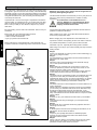
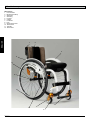
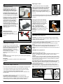
Helium
Directions for use
2
Helium Rev. 1
Table of contents
Dear Customer,
We are very pleased that you have decided in favour of a highquality SUNRISE MEDICAL product.
This Owner’s manual will provide numerous tips and ideas so that
your new wheelchair can become a trustworthy and reliable partner
in your life.
For Sunrise Medical, it is very important that we have a good
relationship with our customers. We like to keep you up-to-date
about new and current developments at our company. Keeping
close to our customers means: fast service, as little red tape as
possible, working closely with customers. When you need
replacement parts or accessories, or if you just have a question
abour your wheelchair – we are there for you.
We want you to be satisfied with our products and service. At
Sunrise Medical we are constantly working to develop our products
further. For this reason, changes can occur in our palette of
products with regard to form, technology, and equipment.
Consequently, no claims can be construed from the data or pictures
contained in this Owner’s manual.
The management system of SUNRISE MEDICAL is certified to
EN ISO 9001, ISO 13485 and ISO 14001.
As the manufacturer, SUNRISE MEDICAL, declares that the
lightweight wheelchairs conform to the 93/42/EWG guideline.
Please contact your local, authorised SUNRISE MEDICAL dealer if
you have any questions regarding the use, maintenance or safety
of your wheelchair.
In case there is no authorised dealer in your area or you have any
questions, contact Sunrise Medical either in writing or by telephone.
Foreword about wheelchairs
General safety notes and driving limits . . . . . . . . . . . . . . . . . . . 4 – 5
Guarantee . . . . . . . . . . . . . . . . . . . . . . . . . . . . . . . . . . . . . . . . . . . . 5
Wheelchair components . . . . . . . . . . . . . . . . . . . . . . . . . . . . . . . . . 6
Handling . . . . . . . . . . . . . . . . . . . . . . . . . . . . . . . . . . . . . . . . . . . . . 7
Step tubes . . . . . . . . . . . . . . . . . . . . . . . . . . . . . . . . . . . . . . . . . . . . 7
Brakes . . . . . . . . . . . . . . . . . . . . . . . . . . . . . . . . . . . . . . . . . . . . . . . 7
Footplates . . . . . . . . . . . . . . . . . . . . . . . . . . . . . . . . . . . . . . . . . . . . 8
Castors . . . . . . . . . . . . . . . . . . . . . . . . . . . . . . . . . . . . . . . . . . . . . . 8
Seat . . . . . . . . . . . . . . . . . . . . . . . . . . . . . . . . . . . . . . . . . . . . . . . . . 8
Wheel alignment . . . . . . . . . . . . . . . . . . . . . . . . . . . . . . . . . . . . 8 - 9
Backrest . . . . . . . . . . . . . . . . . . . . . . . . . . . . . . . . . . . . . . . . . . . . . .9
Push handles . . . . . . . . . . . . . . . . . . . . . . . . . . . . . . . . . . . . . . . . . . 9
Lap belt . . . . . . . . . . . . . . . . . . . . . . . . . . . . . . . . . . . . . . . . . . 10 - 11
Anti-tip tubes . . . . . . . . . . . . . . . . . . . . . . . . . . . . . . . . . . . . . . . . . 10
Crutch holder . . . . . . . . . . . . . . . . . . . . . . . . . . . . . . . . . . . . . . . . . 10
Tyres and mounting . . . . . . . . . . . . . . . . . . . . . . . . . . . . . . . . . . . . 11
Maintenance and care . . . . . . . . . . . . . . . . . . . . . . . . . . . . . . . . . . 11
Trouble-shooting . . . . . . . . . . . . . . . . . . . . . . . . . . . . . . . . . . . . . . 12
Disposal / Recycling of materials . . . . . . . . . . . . . . . . . . . . . . . . . .12
Nameplate . . . . . . . . . . . . . . . . . . . . . . . . . . . . . . . . . . . . . . . . . . . 12
Technical data . . . . . . . . . . . . . . . . . . . . . . . . . . . . . . . . . . . . 13 - 15
Torque . . . . . . . . . . . . . . . . . . . . . . . . . . . . . . . . . . . . . . . . . . . . . . 16
Notes . . . . . . . . . . . . . . . . . . . . . . . . . . . . . . . . . . . . . . . . . . . . . . . 17
Sunrise Medical Limited
High Street, Wollaston
West Midlands DY8 4PS
Telephone: 01384 44 66 66
Telefax: 01384 44 66 99
E-mail: [email protected]
Internet: www.sunrisemedical.co.uk
Use
IMPORTANT:
DO NOT USE YOUR
WHEELCHAIR UNTIL
THIS MANUAL HAS
BEEN READ AND
UNDERSTOOD.
Wheelchairs are exclusively for a user who is unable to walk or has
limited mobility, for their own personal use.
Warranty can only be taken on if the product is used under the
specified conditions and for the intended purposes. The expected
life of the wheelchair is 5 years. DO NOT fit or use replacement
parts from other manufacturers with this wheelchair.
The range of fitting variants as well as the modular design mean that
it can be used by those who cannot walk or have limited mobility
because of:
• Paralysis
• Loss of extremity (leg amputation)
• Extremity defect/deformity
• Joint contractures/joint injuries
• Illnesses such as heart and circulation deficiencies, disturbance of
equilibrium or cachexia.
When considering provision, please also note the body size, weight,
physical and psychological constitution, the age of the person, living
conditions and environment.
Helium Rev. 1
3
ENGLISH
Foreword
General safety notes and driving limits
The construction of this wheelchair, as well as the technology used,
is designed to give the maximum level of safety. International safety
standards currently in force have either been fulfilled or exceeded in
parts. Nevertheless, users may put themselves at risk by improperly
using their wheelchairs. For your own safety, the following rules
must always be observed.
ENGLISH
Unprofessional or erroneous changes or adjustments increase the
risk of accident. As a wheelchair user, you are also part of the daily
traffic on streets and pavements, just like anyone else. We would
like to remind you that you are, therefore, subject to any and all
traffic laws.
Maximum user weight: 120 kg. Please note the weight limits for
separately fitted lightweight options.
This wheelchair should be used exclusively to convey one person at
a time. Any other use beyond this limit is in violation of safety
regulations.
Your wheelchair is not suitable for use in
vehicles. DO NOT sit on the wheelchair during
any transportation in a vehicle; always use a
properly secured vehicle seat!!
Be careful during your first ride in this wheelchair. Get to know your
wheelchair.
Only permanently installed seats and seat belts will offer sufficient
protection in hazardous situations.
Before each use, the following should be checked:
• Quick-release axles on the rear wheels
• Velcro on seats and backrests
• Tyres, tyre pressure and wheel locks.
When vehicles are in motion, unoccupied wheelchairs should be
secured using appropriate means.
Before changing any of the adjustments of this wheelchair, it is
important to read the corresponding section of the Owner’s manual.
It is possible that potholes or uneven ground could cause this
wheelchair to tip over, especially when riding uphill or downhill.
Before changing any of the adjustments of this wheelchair, it is
important to read the corresponding section of the Owner’s manual.
When riding over a step or up an incline frontally, the body should be
leaning forward.
> 10°
> 10°
4
Helium Rev. 1
Danger!
Secure your wheelchair on uneven ground or when transferring (e.g.
into a car) by using the brakes.
Danger!
For high amputees you must position the rear wheels towards the
back and/or use anti-tip tubes.
Danger!
With active centre of gravity adjustment, the wheelchair may tip
over, so anti-tip tubes should be used.
Danger!
Before setting off, check that your tyre pressure is correct. The
correct tyre pressure is printed on the edge of the wheel, for rear
wheels it should be at least 3.5 bar ( 350 kPa).
All brakes will only work if there is sufficient tyre pressure and if the
correct setting has been made (see the Chapter on "Brakes").
Danger!
The wheel locks are not intended to brake your wheelchair. They are
only there to ensure that your wheelchair does not begin rolling
unintentionally. When you stop on uneven ground/floors, you should
always use the wheel locks to prevent such rolling. Always apply
both wheel locks, otherwise your wheelchair could tip over.
Caution!
The wheel locks have not been designed to be used as brakes for a
moving wheelchair.
Always make use of elevators and ramps. If these are not available,
you can reach your destination with the aid of two attendants. They
should grip the wheelchair at securely mounted parts. If your
wheelchair is equipped with anti-tip tubes, these should be folded
away. A wheelchair should never be lifted with an occupant; it should
only be pushed.
Danger!
Do not lift or carry your wheelchair on back tubes or push handles.
Danger!
If the seat and back sling are damaged, you must replace them
immediately.
Danger!
Be careful with fire, in particular with burning cigarettes. Seat and
back slings can set on fire.
Danger!
To avoid injuries to the hand when operating the wheelchair, do not
grip between the rear wheel and brakes.
Danger!
If a journey in a specially fitted vehicle for disabled people is
required, the user should use the seats in the vehicle and the
appropriate restraint system.
Danger!
Always make sure that the quick-release axles on the rear wheels
are set properly. If the button on the quick-release axle is not
pressed in, the rear wheel cannot be removed.
Note: This guarantee cannot be transferred.
4) The guarantee also covers all repaired or replaced parts for the
remaining period of the guarantee for the wheelchair.
5) For spare parts which are fitted after the start of the original
guarantee, we give a further 24-month guarantee.
6) Consumable parts are normally excluded from the guarantee,
except in the case that premature wear of the part is the direct result of a manufacturing fault. These parts include, amongst others,
upholstery, tyres, inner tubes and similar parts.
7) The guarantee conditions above cover all product parts for
models which were purchased at full sales price.
8) Normally we do not accept responsibility if a repair or replacement of the wheelchair is required for one of the following reasons:
a) The product or part has not been maintained or serviced in accordance with the manufacturer's recommendations as shown in
the User Instructions and/or the Service Instructions. Accessories
have been used which are not specified as original accessories.
b) The wheelchair or a part of the wheelchair was damaged
through neglect, accident or improper use.
c) Alterations to the wheelchair or parts, which are not in accordance with the manufacturer's specifications or the carrying out of
repairs before informing the authorised dealer.
Operating conditions:
The wheelchair can be used indoors as well as outdoors on dry,
relatively smooth surfaces. It should not be used in heavy rain, on
snow-covered and/or slippy surfaces.
Guarantee
Guarantee
THIS DOES NOT AFFECT YOUR LEGAL RIGHTS IN ANY WAY.
Guarantee conditions
1) Repair or replacement is carried out by the authorised Sunrise
Medical dealer.
2) To fulfil the guarantee conditions, should servicing need to be
carried out on your wheelchair under this agreement, contact the
designated Sunrise Medical authorised dealer immediately, with
precise details on the type of difficulty. Should you be using the
wheelchair outside the area covered by the designated Sunrise
Medical authorised dealer, the work will be carried out under
"guarantee conditions" by another dealer as designated by the
manufacturer.
3) Should a part or parts of the wheelchair require repair or replacement within 24 months (5 years for frame and cross-brace)
Helium Rev. 1
5
ENGLISH
Danger!
In particular when using lightweight metal handrims, fingers will
easily become hot when braking from a high speed or on long
inclines.
Danger!
If the wheelchair is subject to direct sunlight for a long period of
time, then parts of the wheelchair (e.g. frame, legrests, brakes and
sideguard) may become hot (>41°C).
Note!
When using the chair outside, always wear leather gloves which
will increase your grip and protect the fingers from dirt and
overheating.
Note!
The effect of the brakes as well as the general driving
characteristics are dependant on tyre pressure. The wheelchair is
significantly lighter and easier to manoeuvre when the rear wheels
are pumped up correctly and both wheels have the same pressure.
Note!
Make sure that your tyres have sufficient tread!
Please note that you are subject to any and all traffic laws when
driving in public traffic.
Note!
Before using the wheelchair for the first time, the user must receive
the necessary instruction.
Note!
When it is dark, please wear light clothing or clothing with
reflectors, so that you can be seen more easily. Make sure that the
reflectors on the side and back of the wheelchair are clearly visible.
We would also recommend that you fit an active light.
Note!
Do not use the wheelchair on slopes > 10°.
Do not use the wheelchair on muddy or icy ground.
Only use the wheelchair in areas which are permitted for
pedestrians.
Note!
When working with or making adjustments to your wheelchair, be
careful not to get your fingers caught!
Please keep a note of your local service agent's address and
telephone number in the space provided.
In the event of a breakdown, contact them and try to give all
relevant details so they can help you quickly.
The wheelchairs shown and described in this user guide may not
correspond in every detail exactly to your own model. However, all
instructions are completely relevant, regardless of possible detail
differences.
The manufacturer reserves the right to alter without notice any
weights, measurements or other technical data shown in this
manual. All figures, measurements and capacities shown in this
manual are approximate, and do not constitute specifications.
after transfer of ownership to the original purchaser, and provided
that this person is still the owner of the wheelchair as a result of a
specific manufacturing or material defect, the part or parts will be
repaired or replaced free of charge, if the wheelchair is returned to
the authorised Sunrise Medical dealer.
Wheelchair components
ENGLISH
Wheelchairs:
1. Push handles
2. Backrest upholstery
3. Sideguard
4. Seat sling
5. Footrest
6. Castors
7. Footboard
8. Fork
9. Quick-release axle
10. Wheel locks
11. Handrim
12. Rear wheel
1
2
3
4
11
9
5
12
7
8
10
6
Helium Rev. 1
6
Quick-release axles on rear wheel
The rear wheels are equipped with
quick-release axles.
The wheels can, therefore, be
installed or removed without using
tools.
To remove a wheel, simply depress
the quick-release button on the axle
(1) and pull it out (Fig. 1).
Options - Brakes
Fig. 1
CAUTION:
1
Hold the quick-release button on
the axle depressed when inserting
the axle into the frame to mount the rear wheels.
Release the button to lock the wheel in place. The quick-release
button should snap back to its original position
Fig. 2
Transporting the chair
Removing the rear wheels will keep
the chair as compact as possible. The
backrest can be folded down by
pulling the cord (1) (see picture 3)
located on the backrest (Fig. 2 + 3).
Fig. 3
1
Options – Step Tubes
Step Tubes
Step tubes are used by attendants to push a wheelchair over an
obstacle. Simply step on the tube to push a wheelchair, for example,
over a kerb or step.
Getting into your wheelchair on your own
Fig. 4a
• Push the wheelchair to a wall or a solid piece
of furniture;
• Apply the brakes;
• The user can lower themselves into the
wheelchair;
• Then position the feet in front of the heel
straps (Fig. 4a).
Getting out of your wheelchair on your own
• Apply the brakes;
Fig. 4b
• With one hand on the wheel or sideguard, the
person should lean forwards slightly, to
transfer the body weight to the front edge of
the seat and then push up to an upright
position with both feet firmly on the floor and
one foot behind the other (Fig. 4b).
CAUTION – Braking power can be
affected by incorrect fitting and
adjustment of the brakes, as well as
tyre pressure which is too low.
Fig. 5
Wheel locks
Your wheelchair is equipped with two
wheel locks. They are applied directly
against the tyres. To engage, press both
brake levers forward against the stops. To
release the locks, pull the levers back to
their original positions.
Braking power will decrease with:
• Worn tyre tread
• Tyre pressure that is too low
• Wet tyres
• Improperly adjusted wheel locks.
Fig. 6
The wheel locks have not been designed
to be used as brakes for a moving
wheelchair. The wheel locks should
therefore never be used to brake a
moving wheelchair. Always use the handrims for braking. Make sure that the gap
3 mm
between the tyres and wheel locks
complies with given specifications. To
re-adjust, loosen the screw and set the appropriate gap. Then
re-tighten the screw (Fig. 5 and 6).
ENGLISH
Handling
CAUTION:
After each adjustment of the rear wheels, check the wheel lock
gap and re-adjust if necessary.
Brake lever extension
The longer lever helps to minimise the
effort needed to set the wheel locks.
The brake lever extension is screwed to the
brakes. By raising this, it can be flipped
forward (Fig. 7).
Fig. 7
CAUTION:
Mounting the wheel lock too close
towards the wheel will result in a higher
effort to operate. This might cause the
brake lever extension to break!
Leaning onto the brake lever extension while transferring will
cause the lever to break! Splashing water from tyres might
cause the wheel lock to malfunction.
CAUTION:
Incorrect mounting of the wheel lock will result in a higher
effort to operate.
This might cause the wheel lock extension lever to break.
Compact brakes
Compact brakes are underneath the seat
sling and are operated by pulling the
brakes towards the rear, in the direction of
the tyre. For the brakes to work properly,
this must be pulled until it reaches the
stops.
Fig. 7
Helium Rev. 1
7
Adjusting the castor
Options - Footplate Adjustment
Adjusting the footrest
CAUTION: Do not stand on the
footboard! Even if the user is
sitting in the chair, there is still a
risk of tipping over and injury.
To ensure that both forks are set parallel,
simply count the teeth visible on both sides.
After setting the castor fork, the teeth will
guarantee a secure position, allowing an
adjustment of 16° in 2° increments. Use the
flat side on the front of the castor fork to
check for a right-angled position to the ground
(Fig. 11)
Fig. 8
1
CAUTION: When transferring, do
not stand on the footboard, there
is a risk of tipping over and injury.
ENGLISH
Releasing the screw (1) will allow you
to adjust the footrest to correspond to
the length of your lower leg and
re-attach the footrest. The angle of
the footrest may be individually
adjusted by loosening screws (2).
The side protection (3) on the
footrest prevents the feet slipping off
accidentally. Make sure that after any
adjustment work, all screws are
tightened correctly (see the page on
torque) (Fig. 8).
Fig. 11
The patented design allows the castor fork to be turned, so that it
can be reset at right-angles to the ground when the seat angle is
changed.
Fig. 8
Setting the directional stability
3
Release the Allen screws (1) on the
underside of the fork. You can then
undo the screw (2). You can now turn
the black socket (3) left or right.
Left – chair pulls to the left
Right – chair pulls to the right
Then tighten up the screw (2) again.
Please set a 90° angle from the fork to
the floor.
Now tighten up the screw (1) again.
(Fig. 12).
2
High-mount footrest
Fig. 9
The high-mount footrest is fitted on
the inner part of the frame
and permits a higher footrest position
(Fig. 9).
Fig. 12
2
3
1
Options - Wheel alignment
Adjusting the wheel alignment
Important: To achieve the very best movement, the rear wheels
must be adjusted to their optimum position, which means correctly
adjusting the wheel alignment.
Options – Seat
Adjusting the seat height
To adjust the rear seat height release
the Allen screws (1) (one on each side),
which fix the clamp to the axle stem (2).
Remove the spacer bracket (3), to
adjust the seat height +/- 1 cm. For
large adjustments, reduce the length of
the axle stem as required.
Tighten the 2 Allen screws to 7 Nm.
(Fig. 10).
Fig. 10
2
1
3
NOTE:
An adjustment to the castor angle may be necessary when adjusting
the rear seat height .
Seat sling
To tighten the upholstery, please use the straps below the
upholstery.
Options - Castors
Castor, Castor adapter, Castor fork
From time to time the wheelchair may veer slightly to the right or left,
or the castors may flutter. This may be caused by the following:
• The forward or reverse wheel motion has not been set properly.
• The castor angle has not been adjusted properly.
• Castor and/or rear wheel air pressure is incorrect; wheels do not
turn smoothly.
The optimum adjustment of the castors is required for the
wheelchair to run in a straight line.
Castors should always be adjusted by an authorized dealer. The
castor plates must be re-adjusted, and the wheel locks must be
checked any time the rear wheel position has been altered.
8
Helium Rev. 1
To do this, measure the distance between both wheels front and rear
to ensure that they are parallel to one another.
The difference between both measurements should not exceed
5 mm.
To adjust the wheels to make them parallel, loosen the screws and
turn the axle sleeve accordingly. Make sure that after any
adjustment work, all screws are tightened correctly (see the page on
torque).
HELIUM tracking adjustment
Setting the toe-in/toe-out to zero
NOTE: A wheelchair with 0° camber cylinders cannot have toe-in or
toe-out. This setting is necessary only with 3° and 6° camber
cylinders.
The term "toe-in or toe-out" defines how well the rear wheels of the
chair are aligned in relation to the ground. This determines how well
the chair will run. Normal resistance or rolling resistance is present
when toe-in is set to zero.
To set toe-in/toe-out to zero: loosen the Allen screws (1) (1 on each
side), which secure the angle tube clamp. Check the ball in the
horizontal (2) plane and turn the angle tube (3) until the ball is in the
centre. Toe-in is now zero.
Before tightening the screws (1), check that the camber tube is
centred left-to-right. The gap should be the same on both sides, or
there should be no gap at all. Tighten the screws to 7 Nm. (Fig. 13 15).
Fig. 13
Fig. 14
1
Fig. 15
Adjusting the rear wheelbase width
The rear wheelbase is defined as the distance between the upper
side of the rear wheels and the backrest tubes, and is represented
by factory setting (1.25 cm). This has to be increased if a larger gap
between the tyres and the optional height-adjustable armrests has to
be created (Fig. 16).
NOTE: When adjusting the rear wheelbase, adjust first one wheel
then the other. If both sides are
Fig. 16
loosened at the same time, this will
alter the toe-in/toe-out adjustment. To
adjust the rear wheelbase, the parts of
the camber (4) move telescopically into
5
4
or out of the camber tube (5), and lock
6
into place when they reach the end.
Loosen screw (6) (located closest to the
camber tube) on the left side of the
chair. Move the quick-release axle inwards or outwards to achieve
the desired wheelbase. Tighten the screws to 7 Nm. Repeat
this procedure on the right side of the chair and adjust the gap so
that it is the same amount as on the left side.
Adjustable back sling
The adjustable back sling can be
adjusted for tension by using several
straps.
The back sling upholstery can be
accessed from the inside via an
opening and can be padded to suit
individual tastes (Fig. 19).
Height-adjustable backrest
The backrest may be set to various
back heights, in 2.5 cm steps. The
adjustment ranges are 25- 30 cm, 3035 cm, 35- 40 cm and 40- 45 cm.
Release the screws (1+2) and set the
backrest to the desired height. Tighten
up the screws again (see the page on
torque). (Fig. 20).
Fig. 19
Fig. 20
2
1
Angle-adjustable back
Fig. 17
The backrest angle is adjusted by
2
altering the position of the pin in
the backrest mounting. The pin (1)
1
must be completely clicked into
place in the hole pattern on both
sides, this gives you an angle
adjustment of 8.5°.
Fit the red plastic pins into the
unused holes. To reach a smaller angle increment (3.5°), you open
the allen key screw (2) and re-set the screw into the second hole.
Please use the relevant torque force (see matrix) to tighten the
screw (2).
This gives you 12° change in the back angle. Then move the pin (1)
in the opposite direction to the next hole, which gives you 12° - 8°=
3.5° change. (Fig. 17)
To reduce the play in the backrest,
Fig. 18
the nut (1) can be released, then the
optimal position can be set using the
set screw (2). Then re-tighten the
1
2
nut (1). (Fig. 18).
CAUTION: The screws must be
re-tightened. Otherwise the angle
adjustment will be lost.
Folding backrest
Release the backrest by pulling the cord. At the same time, push it
forward to fold it down. To return the backrest to its original position,
this must be pulled back as far as possible, until it locks into place
on both sides.
CAUTION: When folding the backrest down, please make sure
that your fingers do not get caught.
ENGLISH
Options - Backrest
Options – Push Handles
Height-adjustable push handles
Fig. 21
These handles are secured with pins to
prevent them from sliding out unintentionally.
2
Opening the quick-release lever (1) makes it
possible to adjust the height of the push
handles (2) to meet your individual needs. As
you move the lever, you will hear a locking
mechanism; you can now easily position the
1
push handle as desired. The nut on the
tension lever determines how tightly the push
handles are clamped into place. If the nut is
loose after adjusting the tension lever, the push handle will also be
too loose. Turn the push handle from side to side before use to
make sure that it is clamped securely enough into place. After
adjusting the handle height, always clamp the tension lever (1)
securely into place. If the lever is not secure, injuries could result
when ascending stairs. (Fig. 21).
NOTE – If the height-adjustable push handles are not fitted properly,
there is a risk that these will develop "play" or that they move out of
position. Please make sure that the relevant screws are tightened
correctly.
Fold-down push handles
If the push handles are not in use, they
can be folded down depressing the
button (2). When they are needed
again, simply flip them back up until
they click into place. (Fig. 22).
Fig. 22
Helium Rev. 1
9
Options – Anti-Tip Tubes
Sunrise Medical recommends anti-tip
tubes for all chairs. When fitting anti-tip
tubes, use a torque of 7 Nm.
Options – Lap belt
Fig. 23
1. Slotting the anti-tip tubes into the
clamp:
a. Press the rear button on the anti-tip
tube on the anti-tip tube adapter, so
that both release pins are drawn
inwards
.b. Slot the anti-tip tubes (1) into the
anti-tip tube adapter.
c. Turn the anti-tip tubes downwards until the release pin locks into
the clamp.
d. Fit the second anti-tip tube in the same way.
ENGLISH
2. Adjusting the anti-tip tubes
To achieve the correct ground clearance of approx. 1" to 2" (2.5 cm
to 5.0 cm), the anti-tip tubes must be raised or lowered.
Press the anti-tip tube release button, so that both release pins are
drawn inwards. Move the inner tube up or down to slot into the
height holes provided. Release the button. Fit the second anti-tip
wheel in the same way. Both wheels should be at the same height.
(Fig. 23).
Danger!
If the anti-tip tubes are not fitted, or have been fitted incorrectly,
there is a risk of tipping over and of injury.
Before using your wheelchair ensure
the lap belt is worn.
Fig. 24
The lap belt must be checked on a daily
basis to ensure it is free from any
obstruction or adverse wear.
Always make sure that the lap belt
is correctly secured and adjustedprior to use. Too loose a strap could
cause the user to slip down and risk
suffocation or cause serious injury.
The lap belt is fitted to the wheelchair as
shown in the illustrations. The seat belt
comprises 2 halves. They are fitted using the
existing seat stay retaining bolt fitted through
the eyelet on the belt. The belt is routed
under the rear of the side panel. (Fig. 24)
Fig. 25
Adjust the belt position so buckles are in the
centre of the seat. (Fig. 25)
Adjust lap belt to suit the user’s needs as follows:
To reduce the belt
length
To increase the belt length
Options – Crutch holder
Crutch holder
This device permits crutches to be transported directly on the
wheelchair. It has a Velcro loop to fasten crutches or other aids.
CAUTION!
Never try to use or even remove the crutches or other aids
while moving.
Feed free belt back Feed free belt through slide adjusters and
through male buckle male buckle to provide more belt length.
and slide adjusters.
Ensure belt is not
looped at male
buckle.
When fastened check space
between the lap belt and user.
When correctly adjusted it should
not be possible to insert more than
the flat of the hand between the
lap belt and the user. (Fig. 26)
Fig. 26
The lap belt should be fixed so that the belt
sits at an angle of 45 degrees across the users
pelvis. The user should be upright and be as
far back as possible in the seat when correctly
adjusted. The lap belt should not allow the user
to slip down in the seat.
(Fig. 27)
10
Helium Rev. 1
Fig. 27
Maintenance and care
To release belt:
Press exposed sides of male
buckle and push towards centre
whilst gently pulling apart.
If in doubt about the use and operation of the lap belt
then ask your healthcare professional, wheelchair
dealer, carer or attendant for assistance.
Advice to client
The lap belt must only be fitted by an approved Sunrise Medical
dealer / agent. The lap belt should only be adjusted by a
professional, or a Sunrise Medical approved dealer / agent.
The lap belt must be checked on a daily basis to ensure it is
adjusted correctly and free from any obstruction or adverse wear.
Sunrise Medical does not encourage the transportation of any
person in a vehicle using this lap belt as a method of restraint.
Please see Sunrise Medical transit booklet for further advice on
transportation.
Maintenance:
Check lap belt, and securing components, at regular intervals for
any sign of frays or damage. Replace if necessary.
NOTE:
The lap belt should be adjusted to suit the end user as detailed
above. Sunrise Medical recommend that the length and fit of the belt
be checked on a regular basis to reduce the risk of the end user
inadvertently re-adjusting the belt to an excessive length.
Tyres and Mounting
Solid rubber tyres are standard.
With pneumatic tyres always make sure that the tyres have the
correct air pressure, as otherwise the performance of the wheelchair
may be affected. If the tyre pressure is too low, rolling resistance will
increase, requiring more effort to move the chair forward. Low tyre
pressure also has a negative impact on manoeuvrability. If the tyre
pressure is too high, the tyre could burst. The correct pressure for a
given tyre is printed on the surface of the tyre itself.
CAUTION:
Sand and sea water (or salt in the winter) can damage the
bearings of the front and rear wheels. Clean the wheelchair
thoroughly after exposure.
The following parts can be removed and sent back to the
manufacturer/dealer for repair:
• Rear wheels
• Armrest
• Footrest holder
• Anti-Tip tubes
ENGLISH
To fasten buckle:
Firmly push male buckle into
female buckle.
• Check the tyre pressure every 4 weeks. Check all tyres for wear
and damage.
• Check the brakes approximately every 4 weeks to make sure that
they are working properly and are easy to use.
• Change tyres as you would an ordinary bicycle tyre.
• All of the joints that are critical to using your wheelchair safely are
self-locking nuts. Please check every three months to make sure
that all bolts are secure (see the section on torque). Safety nuts
should only be used once and should be replaced after use.
• Please use only mild household cleansers when your wheelchair is
dirty. Use only soap and water when cleaning the seat upholstery.
• If your wheelchair should ever get wet, please dry it afterwards.
• A small amount of sewing-machine oil should be applied to quickrelease axles approximately every 8 weeks. Depending on the
frequency and type of use, we recommend taking your wheelchair to
your authorised dealer every 6 months to have it inspected by
trained personnel.
These components are available as spare parts. For further
information, please see the spare parts catalogue.
Hygiene measures when being re-used:
Prior to the wheelchair being re-used, it must be carefully prepared.
All surfaces which come into contact with the user must be treated
with a disinfection spray.
To do this, you must use a disinfectant from the DGHM list, e.g.
Antifect Liquid (Schülke & Mayr) for rapid alcohol-based disinfection
for medical products and medical devices, which must be disinfected
quickly.
Please take into account the manufacturer's instructions for the
disinfectant you are using.
In general, a complete disinfection cannot be guaranteed on seams.
We therefore recommend that you dispose of seat and back slings
to avoid microbacterial contamination with active agents according
to § 6 infection protection law.
Tyres are mounted the same way as an ordinary bicycle tyre. Before
installing a new inner tube, you should always make sure that the
base of the rim and the interior of the tyre are free of foreign objects.
Check the pressure after mounting or repairing a tyre. It is critical to
your safety and to the wheelchair’s performance that regulation air
pressure be maintained and that tyres be in good condition.
Helium Rev. 1
11
Disposal / Recycling of materials
If the wheelchair has been made available to you free of charge,
then it does not belong to you. If it is no longer required, then
follow the instructions to return it as given by the organisation
that made the wheelchair available to you.
Nameplate
Nameplate
The nameplate is located on either the cross-tube assembly or the
transverse frame tube, as well as on a label in the owner’s manual.
The nameplate indicates the exact model designation and other
technical specifications. Please provide the following pieces of
information whenever you have to order replacement parts or to file
a claim:
• Serial number
• Order number
• Month/Year
ENGLISH
In the following section, there is a description of the materials used
on the wheelchair, in view of the disposal or recycling of the
wheelchair and its packaging.
Particular regulations with regard to disposal or recycling may be in
force locally and these must be taken into account when performing
disposal. (This can include the cleaning or decontamination of the
wheelchair prior to disposal).
Aluminium: Castor forks, wheels, sideguards for the chassis,
armrest frame, footrest, push handles
Steel: Fixing points, quick-release axle
Plastic: Handles, tube stoppers, castors, footplates, armpads and
12” wheel/tyre
Packaging: Plastic bags made of soft polyethylene, cardboard
Upholstery: Polyester fabric with PVC coating and highlyflammable foam.
Disposal or recycling should be carried out by a disposal company
or at a public disposal point. You can also return your wheelchair to
your dealer for disposal.
Trouble-shooting
Wheelchair pulls to one side
• Check tyre pressure
• Check to make sure wheel turns easily (bearings, axle)
• Check the castor angle
• Check to make sure both castors are making proper contact with
the ground
Castors begin to wobble
• Check the castor angle
• Check to make sure all bolts are secure; tighten if necessary (see
the section on torque)
• Check to make sure both castors are making proper contact with
the ground
Wheelchair / Cross-tube assembly does not snap into position
in the seat saddle
• Chair is still new, i.e., the seat or backrest upholstery is still very
stiff. This will improve with time.
Wheelchair is difficult to fold up
• Adjustable backrest upholstery is too stiff. Loosen it accordingly.
Wheelchair squeaks and rattles
• Check to make sure all bolts are secure; tighten if necessary (see
the section on torque)
• Apply small amount of lubrication to spots where movable parts
come into contact with one another
Wheelchair begins to wobble
• Check angle at which castors are set
• Check tyre pressure
• Check to see if rear wheels are adjusted differently
12
Helium Rev. 1
Technical Data
Overall width:
With standard 25" wheels, including handrims with 6° camber: SW + 30 cm
Overall length: 91 cm with SD 48
Overall height: 112 cm with BH 45
Weight in kg: from 6.4 kg
Maximum load:
Helium 120 kg
Norm
min.
max.
Overall length
with footrest
770 mm
1050 mm
Overall width
620 mm
Folded length
Norm
min.
max.
Seat surface
angle
0°
15°
760 mm
Effective seat
depth
340 mm
480 mm
N/A
N/A
Effective seat
width
320 mm
460 mm
Folded width
N/A
N/A
Seat height at
the front edge
430 mm
550 mm
Folded height
N/A
N/A
Backrest angle
60°
115°
Total weight
6.4 kg
13.0 kg
Back height
250 mm
450 mm
Weight of
the heaviest
individual part
-
2.1 kg with
24" rear
wheel
Distance from
the footrest to
the seat
350 mm
500 mm
Static stability downhill
10°
10°
Angle from leg
to seat
95°
110°
Static stability
- uphill (with
anti-tip tube)
10°
10°
Distance from
the armrest to
the seat
N/A
N/A
Static stability sidewards
10°
10°
Front position
of the armrests
N/A
N/A
Dynamic
stability uphill Power
consumption
N/A
N/A
Handrim
diameter
540 mm
567 mm
Overcoming
obstacles
N/A
N/A
Horizontal axle
position
+ 56 mm
+ 11 mm
The wheelchair conforms to the following standards:
a) Requirements and tests for static strength, impact resistance and fatigue strength (ISO 7176-8) b) Drive and control systems for power wheelchairs, requirements and test (ISO 7176-14) c) Environmental test in accordance with ISO 7176-9 d) Flammability resistance of upholstered parts in accordance with ISO 7176-16 (EN 1021-1/2)
ENGLISH
Seat heights:
The choice of frames, forks and castors, as well as the rear wheel size (24", 25") determines the seat heights
which can be achieved.
Yes •
n.a. •
n.a. •
Yes •
Helium Rev. 1
13
Technical Data
Castor
Fork
Type of frame
low
98 mm x 32 mm
high
3"
low
111 mm x 32 mm
ENGLISH
high
low
98 mm x 32 mm
high
low
111 mm x 32 mm
high
4"
low
111 mm x 45 mm
high
low
123 mm x 45 mm
high
14
Helium Rev. 1
Front seat height
in cm
43
44
45
47
48
49
44
45
46
48
49
50
44
45
46
48
49
50
45
46
47
49
50
51
45
46
47
49
50
51
45
46
47
48
49
50
51
52
Rear seat height
in cm
43 - 30
44 - 31
45 - 32
47 - 34
48 - 35
49 - 36
44 - 31
45 - 32
46 - 33
48 - 35
49 - 36
50 - 37
44 - 31
45 - 32
46 - 33
48 - 35
49 - 36
50 - 37
45 - 32
46 - 33
47 - 34
49 - 36
50 - 37
51 - 38
45 - 32
46 - 33
47 - 34
49 - 36
50 - 37
51 - 38
45 - 32
46 - 33
47 - 34
48 - 35
49 - 36
50 - 37
51 - 38
52 - 37
Technical Data
Fork
Type of frame
low
98 mm x 32 mm
high
low
111 mm x 32 mm
high
5"
low
111 mm x 45 mm
high
low
123 mm x 45 mm
high
low
6"
123 mm x 45 mm
high
Front seat height
in cm
46
47
50
51
46
47
48
50
51
52
47
48
51
52
47
48
49
50
51
52
53
54
50
51
54
55
Rear seat height
in cm
46 - 33
47 - 34
50 - 37
51 - 38
46 - 33
47 - 34
48 - 35
50 - 37
51 - 38
52 - 39
47 - 34
48 - 35
51 - 38
52 - 39
47 - 34
48 - 35
49 - 36
50 - 37
51 - 38
52 - 39
53 - 40
54 - 41
50 - 37
51 - 38
54 - 41
55 - 42
Helium Rev. 1
ENGLISH
Castor
15
ENGLISH
Torque
Torque
If no other information is given, the torque for M6 screws is
7 Nm.
16
Helium Rev. 1
ENGLISH
ENGLISH
Notes
Helium Rev. 1
17
Sunrise Medical GmbH & Co.KG
Kahlbachring 2-4
69254 Malsch/Heidelberg
Germany
Tel.: +49 (0) 7253/980-0
Fax: +49 (0) 7253/980-111
www.sunrisemedical.com
Sunrise Medical Limited
High Street Wollaston
West Midlands DY8 4PS
England
Tel.: +44 (0) 1384446688
www.sunrisemedical.com
Sunrise Medical S.L.
Polígono Bakiola, 41
48498 Arrankudiaga – Vizcaya
España
Tel.: +34 (0) 902142434
Fax: +34 (0) 946481575
www.sunrisemedical.com
Sunrise Medical S.A.
13, Rue de la Painguetterie
37390 Chanceaux sur Choisille
France
Tel.: +33 (0) 247554400
Fax: +33 (0) 247554403
www.sunrisemedical.com
Sunrise Medical Srl
Via Riva 20, Montale
29100 Piacenza (PC)
Italy
Tel.: +39 0523-573111
Fax: +39 0523-570060
www.sunrisemedical.com
Sunrise Medical A.G.
Lückhalde 14
3074 Muri bei Bern
Switzerland
Tel.: +41 (0) 31-958-3838
Fax: +41 (0) 31-958-3848
www.sunrisemedical.com
Sunrise Medical AS
Rehabsenteret
1450 Nesoddtangen
Norway
Tel.: +47 (0) 66963800
Faks: +47 (0) 66963838
www.sunrisemedical.com
Sunrise Medical AB
Britta Sahlgrens gata 8A
421 31 Västra Frölunda
Sweden
Tel: +46 (0) 31-748 37 00
Fax: +46 (0) 31-748 37 37
www.sunrisemedical.com
Sunrise Medical B.V.
Groningenhaven 18-20
3433 PE Nieuwegein
Nederlands
Tel.: +31 (0) 3060-82100
Fax: +31 (0) 3060-55880
www.sunrisemedical.com
G2 A/S
Graham Bells Vej 21-23 A
8200 Arhus N
Denmark
Tel.: +45 87 41 31 00
Fax: +45 87 41 31 31
www.G2.dk