1
AN-COMM-500
Eurotherm Controls Inc.
TU/TC Series
Intelligent SCR Assemblies
with
Profibus DP Communications
to
S-S Technologies Inc.
5136-PFB-ISA
Direct-Link™
Profibus Interface Card
and the
PFBDDEM1 DDE Server
to
Wonderware’s InTouch
Prepared By:
Eurotherm Controls Inc
(703) 471-4870
www.eurotherm.com
January 1999
HA136387
Issue 1.2
AN-COMM-500
5136-PFB-ISA to TU/TC Series
COPYRIGHTS and TRADEMARKS
Series 2000 is a trademark of Eurotherm Controls, Inc.
Microsoft, Windows, Windows 95, Windows 98, and Windows NT are registered trademarks of Microsoft
Corporation.
Direct-Link is a trademark of SST
Profibus is a registered trademark of the Profibus Trade Organization (PTO)
Wonderware and InTouch are trademarks of Wonderware Corporation
Eurotherm has used all reasonable resources and efforts to indicate and supply information regarding
trademarks used in this application note. The absence of a trademark identifier is not a representation that a
particular word or technology is not a trademark.
Copyright © Eurotherm Controls Inc 1998, 1999. All rights strictly reserved.
No part of this document may be duplicated in any form or by any means without prior written permission
from Eurotherm Controls Inc. Every effort has been taken to ensure the accuracy of this document.
However, in order to maintain our technological lead, we are continuously improving our products which
could, without notice, result in amendments or omissions to this document. We cannot accept
responsibility for damage, injury, loss, or expenses resulting therefrom.
CONTACT INFORMATION
Company
Eurotherm Controls Inc.
Address
11485 Sunset Hills Road
Reston, Virginia 20190
S-S Technologies (SST)
50 Northland Road
Waterloo, Ontario N2V 1N3
Canada
PTO-USA Branch Office
16101 N. 82nd Street
Suite 3b
Scottsdale, Arizona 85260
Corporate Headquarters
100 Technology Drive
Irvine, California 92618
Profibus User Group
Wonderware Corporation
HA136387
i
Numbers/Web
Tel: (703) 471-4870
Fax: (703) 787-3436
www.eurotherm.com
Tel: (519) 725.5136
Fax: (519) 725.1515
www.sstech.on.ca
Tel: (602) 483-2456
Fax: (602) 482-7202
www.profibus.com
Tel: (949) 727-3200
Fax: (949) 727-3270
www.wonderware.com
Issue 1.2
AN-COMM-500
5136-PFB-ISA to TU/TC Series
Introduction
This application note describes a series of steps to configure the Eurotherm TU and TC
Series thyristor (or Silicon Controlled Rectifier - SCR) assemblies with Profibus DP
communications as Slaves to the S-S Technologies (SST) 5136-PFB-ISA Direct-Link
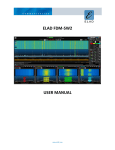
interface card as a Master in a host PC. The TC3001 and TU 1471 are shown in Figure 1.
Subsequently are steps on the configuration of the PFBDDEM1 DDE Server to the 5136PFB-ISA and to Wonderware’s InTouch.
Figure 1. TU/TC Series
The TU Series consists of the 1170/71, 1270/71, 1450/51, 1470/71 and 2170. The 1170
range offers single load capability, the 1270 range offers dual independent load
capability, and the 1450 range offers quad independent load capability – all are capable
of driving into simple or complex loads. This capability is provided by the multi-mode
firing of the units SCR’s which may be single cycle, fast cycle, phase angle, or phase
angle start then fast cycle. The TU 2170 range is designed for 3-phase resistive loads.
All TU Series are capable of V-squared or VxI power control.
HA136387
Page 1 of 37
Issue 1.2
AN-COMM-500
5136-PFB-ISA to TU/TC Series
The CCC (control and comms board) option must be included when ordering the TU
Series for Profibus DP communications.
In the TC Series only the TC3001 is currently available with Profibus DP
communications. The TC3001 is a 3-phase SCR assembly designed to provide precision
control and firing of virtually any type of load whether it is resistive, inductive,
capacitive, 3-wire wye or delta, 4-wire wye, or 6-wire delta.
Hardware/Software Used
The following hardware and software shown in Tables 1 & 2 were used in the generation
of this application note.
Table 1. Hardware Used
Hardware
TU1471
5136-PFB-ISA
PC
Description
Quad SCR Assembly with Profibus DP
communications.
ISA Interface Card for Profibus DP, FDL,
FMS, and MPI interfaces. Card is ¾ length 16
bit ISA bus compatible.
Any PC capable of running the Microsoft
Windows 32 bit operating systems – NT V4.0
(with SP3) or greater is recommended.
Supplier
Eurotherm Controls
SST
N/A
Table 2. Software Used
Software
GSD File Editor
PFBWin32
PFBDDEM1
InTouch
Windows NT
HA136387
Description
Software tool to generate Eurotherm
instrument GSD files. Version 1.10 used.
Profibus Configuration software used to
generate and download interface module
binary file(s). Version 1.08 used.
Master DDE server for the 5136-PFB-ISA
card. Version 1.10 used.
Windows visualization configuration and
run-time software. Version 7.0 (FS2000)
used.
Operating system for PC. Version 4 with
SP3 used.
Page 2 of 37
Supplier
Eurotherm Controls
SST
SST
Wonderware
Corporation
Microsoft
Issue 1.2
AN-COMM-500
5136-PFB-ISA to TU/TC Series
Step-By-Step
The following steps detail the configuration of the hardware and software listed in Tables
1 & 2.
1) Install the PFBWin32 software.
A copy of the SST Profibus Configuration software comes with every 5136-PFB-ISA
interface card or is available for download from the SST web-site. It is a ZIP file that
requires extraction to a temporary subdirectory. The filename is PFBWIN32.ZIP. Unzip
and run setup to install. SST recommends using the default directories.
The SST Profibus Configuration software is a 32-bit application and runs satisfactorily on
the Microsoft Windows 95 or Windows 98 operating system. However, we recommend
installing it on a host computer running Microsoft Windows NT, version 4, with SP3 or
higher.
2) Install 5136-PFB-ISA Direct-Link Profibus interface card – hereafter referred to
as interface card, into the host computer or PC.
The interface card is a ¾ length 16-bit ISA bus card. Be sure that the installer uses
appropriate anti-static precautions before handling the card for installation into the host
computer. Never touch the backplane connectors or pins.
Installation of the interface card requires computer resources in the form of I/O port
address space (8 bytes), 16Kb shared memory segment, and optionally a host interrupt
value. The default I/O base memory address of the interface card is 250, the default
memory segment base address is 0xD000, and the ICR (interrupt) register has a value of
‘none’ which disables interrupts. For this application note, the Transmit (JP5) and Flash
Write (JP6) enable jumper were left in the default position – or enabled (jumpered).
Since only 1 interface card was used the Shared Interrupt (JP3) was left at default –
disabled (open). These settings should work in the majority of installations.
For installations requiring these settings to be modified, jumpers on the interface card set
the I/O base address while the 16KB memory window and interrupt setting require the
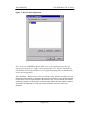
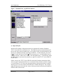
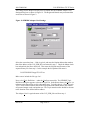
use of the Direct-Link Configuration program – see Figure 2. This program may be
located in the Configuration Tools folder as Direct-Link Configuration.
The Direct-Link Configuration program enables interface card properties to be edited,
new interface cards to be added – for example in a multiple card installation, or existing
interface cards to be deleted. Selecting the Properties command button for the card of
interest brings up the Edit Card Config dialog box shown in Figure 3 that is used to
configure the resource settings the interface card requires.
HA136387
Page 3 of 37
Issue 1.2
AN-COMM-500
5136-PFB-ISA to TU/TC Series
Figure 2. Direct-Link Configuration
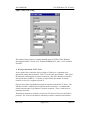
Note: To use the PFBDDEM1 Master DDE server as this application note does, an
interrupt level must be set. Figure 3 shows an Interrupt of 11. Simply click on OK on
both the Edit Card Config and Direct-Link Configuration dialog boxes to automatically
set the card configuration.
The Card Name – shown as Driver250, is a reference to the interface card that is used in
subsequent configuration. It cannot be changed once an interface card configuration has
been created, saved, and downloaded to the interface card. Be sure that the I/O Address
matches the jumpers on the interface card and ensure that the Memory Address segment
start address and Interrupt Level do not conflict with other resources of the host
computer.
HA136387
Page 4 of 37
Issue 1.2
AN-COMM-500
5136-PFB-ISA to TU/TC Series
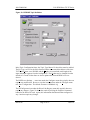
Figure 3. Edit Card Config
The setting of these properties is further detailed in the 5136-PFB, 32-Bit Windows
Development Guide, Version – 0.10, filename PFBWIN.DOC, April 1, 1997 available
from SST.
3) Wiring to Eurotherm TU/TC Series.
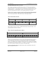
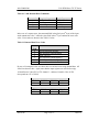
As the speed of this connection may be as high as 12Mb/sec it is important to use
appropriate cabling and termination. Table 3 lists the cable specifications. Table 4 lists
the maximum cable length with respect to baud rate. Stub lines should be avoided for
data speeds above 500kb/sec. A repeater is required when the number of stations
(masters or slaves) in 1 segment exceeds 32.
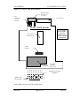
Figure 4 shows the wiring diagram between the interface card and the TU Series. The
interface card has 2 connectors for Profibus network connections – a standard DB9
female connector and a 5-pin Phoenix Combicon connector. These 2 connectors are
internally connected.
The Phoenix connector is not shown wired to the TU Series in Figure 4 as the DB-9 is
preferred. The TU Series terminals to which they would be connected if the Phoenix
HA136387
Page 5 of 37
Issue 1.2
AN-COMM-500
5136-PFB-ISA to TU/TC Series
connector is used is shown in Figure 4. As the Phoenix connector does not have a shield
connection attach the cable shield to a convenient earth ground preferably at the PC end.
Though the Profibus specification recommends that the shield (braiding and if present
shield foil using shield clamps) be connected at both ends, care must be taken to ensure
that differences in local earth potential do not allow circulating currents to flow. If in
doubt, connect the shield at one end only – preferably at the interface card, and that any
cable segments have their shields connected.
It is important that the network cable be terminated at both ends. To use the internal
terminations on the interface card when using the DB-9 or Phoenix connector, jumper 1
to 2 and 4 to 5 on the Phoenix connector.
Table 3. Recommended Profibus Cabling
Characteristic
Impedance:
Cable
capacitance:
Core diameter:
Cable type:
Resistance:
Shielding:
Type A cable
135 to 165Ω at a frequency of 3 to 20
MHz.
< 30 pF per Meter
Type B cable
135 to 165Ω at a frequency of > 100 kHz
Max. 0.34 mm², corresponds to AWG 22
Twisted pair cable. 1x2 or 2x2 or 1x4 lines
< 110 Ohm per km
Copper shielding braid or shielding braid
and shielding foil
Max. 0.22 mm², corresponds to AWG 24
Twisted pair cable. 1x2 or 2x2 or 1x4 lines
Copper shielding braid or shielding braid
and shielding foil
typical < 60 pF per Meter
Belden (belden.com) 3097A or 9182 is recommended, but other choices are available.
For more information refer to the ‘Profibus Product Guide’ produced by the Profibus
User Group – see www.profibus.com.
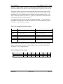
Table 4. Maximum Cable Length
Baud rate (kbit/sec)
Type A cable
Type B cable
HA136387
9.6
1200m
1200m
19.2
1200m
1200m
93.75
1200m
1200m
Page 6 of 37
187.5
1000m
600m
500
400m
200m
1500
200m
-
12000
100m
Issue 1.2
AN-COMM-500
5136-PFB-ISA to TU/TC Series
Figure 4. TU Series Profibus Wiring Diagram
TU Series #1
Bus termination
resistors
ON
OFF
5136-PFB-ISA
Interface Card
(MASTER)
61
62
63
64
65
66
ON
OFF
Profibus
Card DB-9F
Top SHLD 1
B3
IGND 5
IV+ 6
A8
B A 0V A B 5V
Phoenix
Combicon
Term A 5
A4
IGND 3
B2
Term B 1
To TU
TU Series #n
Bus termination
resistors
Terminal 62 (A)
Terminal 61 (B)
ON
OFF
System
Status
61
Comms
Status
62
63
64
65
66
ON
OFF
B A 0V A B 5V
The bus termination resistors should be ‘ON’ for only the last TU/TC Series on the
Profibus DP network.
HA136387
Page 7 of 37
Issue 1.2
AN-COMM-500
5136-PFB-ISA to TU/TC Series
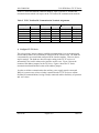
As the TC Series has different connector numbers, Table 5 lists the TC Profibus DP
communication terminals with respect to the TU Profibus DP communication terminals.
Table 5. TU/TC Profibus DP Communication Terminal Assignments
Interface Card
DB-9F
Function
3
B
8
A
TU Series
J4 Connector
61
62
63
64
65
66
Function
B
A
0V
A
B
5V
TC Series
J4 Connector
1
2
3
4
5
6
Function
B
A
0V
A
B
5V
4) Configure TU/TC Series
The only necessary jumper setting to establish communications is to set an unassigned
comms address that is set to match those configured in the interface card. The baud rate
is automatically set to match that configured in the interface module. There are data or
stop bit settings. The baud rate does not require setting in the TU/TC series as it
automatically sets itself to whatever the interface card is set to. Figure 5 shows the
location of the address jumpers for the TU Series. Figure 6 shows the TC Series
communication board and the location of the address jumpers.
In order to validate communications the auxiliary power supply must be connected.
While it is not necessary to have a load(s) connected to the TU/TC Series to validate
Profibus DP communications, having a load(s) connected enables familiarity of operation
and ‘real’ values.
HA136387
Page 8 of 37
Issue 1.2
AN-COMM-500
5136-PFB-ISA to TU/TC Series
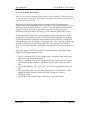
Figure 5. TU Series Control Board Address
TU CONTROL BOARD
Communication
Connector J4
(6 screws)
!!!CAUTION!!!
Do not install or
remove the
Interface board
with the Thyristor
Unit powered
Control Board
Microprocessor
PROFIBUS
Interface
(additional board)
ST16
ST15
ST14
ST13
ST12
ST11
ST23
ST22
ST10
ST9
Address
Selection
Not used
(Communication always active)
1
0
MSB not used
with PROFIBUS
Baud-Rate not used with
PROFIBUS
Address 18 is shown in the example above.
HA136387
Page 9 of 37
Issue 1.2
AN-COMM-500
5136-PFB-ISA to TU/TC Series
Figure 6. TC Series Comm. Board Address
Communication
Connector J4
(6 screws)
Bus
termination
resistors
selection
User connector
TC3001 COMM. BOARD
!!!CAUTION!!!
Do not install or
remove the
Interface board
with the Thyristor
Unit powered
Control Board
Microprocessor
Address
Selection
PROFIBUS
Interface
KD1
KD2
KD3
KD4
KD5
KD6
KD7
KD8
KD9
(additional board)
Baud-Rate not used with
PROFIBUS
1
0
MSB not used
with PROFIBUS
Again, address 18 is shown in the example above.
HA136387
Page 10 of 37
Issue 1.2
AN-COMM-500
5136-PFB-ISA to TU/TC Series
5) Create or Modify the GSD file.
GSD is an acronym of a German phrase meaning ‘Device Database’. GSD files provide
a clear and concise definition of the parameter characteristics of an automation device in
a precisely defined file format.
Determine if the GSD files shipped with the Eurotherm GSD file editor meet the
requirements for the intended application. One GSD for a TU and one GSD for a TC are
shipped as part of the GSD file editor – see Table 6. The Eurotherm GSD file editor is
available for free download at the Eurotherm web-site or the GSD files may be
downloaded from the Profibus User Groups web-site under the GSD Library section.
If the standard GSD files do not meet the application requirements generate a suitable
configuration using the GSD file editor. No manual editing of the GSD file is required.
It is then recommended – though not required, that the saved GSD file be copied to the
GSD subdirectory in the SST Profibus Configurator tools. This is normally located in the
subdirectory Dlink32/5136-pfb/Common/Pbc/Gsd – if the standard file locations are
used. This causes the automatic importing of GSD files into the Slaves hierarchical tree
view.
Some notes about the TU/TC Series Profibus DP implementation with regards to the
GSD file in the Parameterization section:
•
•
•
•
•
There is a maximum of 16 (32 bytes) input words. The Module input word setting
therefore may be no greater than 0x5F.
There is a maximum of 4 (8 bytes) output words. The 4 output words are used only
for demand data (data-exchange). The Module output word setting must remain
0x63.
For example: Module = “TU” 0x5F, 0x63. TU/TC Series supports only 2 bytes are
here.
You cannot enter in the User_Prm_Data output addresses in the GSD file – either
through the GSD file editor or using a text editor. Doing so will cause a
configuration error.
The function of the 4 output words is detailed in a subsequent section.
HA136387
Page 11 of 37
Issue 1.2
AN-COMM-500
5136-PFB-ISA to TU/TC Series
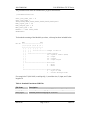
The parameterization from the standard Euro_tu.gsd is shown below.
; Parameterization:
User_Prm_Data_Len = 9
User_Prm_Data =
0x00,0x00,0x04,0x00,0x05,0x00,0x06,0x00,0x07
Max_Input_Len = 32
Max_Output_Len = 8
Max_Data_Len = 40
Module = "TU" 0x53,0x63
Endmodule
To decode the meaning of the Module byte values, a bit map has been included below.
Bit-No
MSB
LSB
+-----------------------+
|7 |6 |5 |4 |3 |2 |1 |0 |
+-----------------------+
| | | | | | | |
| | | | +--+--+--+------| | | |
| | +--+------------------| |
| |
| |
| |
| |
| +------------------------|
|
|
+----------------------------
length of data +1
input/output:
00 - special format (DPV1)
01 - input
10 - output
11 - input/output
data size
0 - Byte
1 - Word
Data consistency
0 - byte or word
1 - entire message frame
For example 0x53 (0101 0011) would specify; 1) word data size, 2) input, and 3) data
length of 4.
Table 6. Standard Eurotherm GSD Files
File Name
Euro_tc.gsd
Euro_tu.gsd
HA136387
Description
Standard parameter mapping for TC Series – see Figure 7.
Standard parameter mapping for TU Series.
Page 12 of 37
Issue 1.2
AN-COMM-500
5136-PFB-ISA to TU/TC Series
Figure 7. Standard Euro_tc.gsd File Parameters
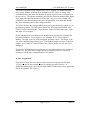
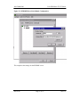
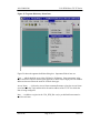
6) Import GSD file.
Start the SST Profibus Configuration software to automatically load the Eurotherm
TU/TC Series GSD files to the Slaves list. The GSD files may not automatically load if
they are not in the expected subdirectory or are invalid. If they do not automatically load
they may be added by manually importing the GSD file. To add a GSD file, first select
the Device menu title, then select the Add Device menu item. An Add Profibus devices
dialog box appears. Make sure to Look in: the GSD subdirectory – or subdirectory where
the GSD files are stored, and select the Euro_tc.gsd file or other TU/TC series GSD file
of your choice.
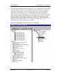
If done correctly, the TU/TC Series GSD files under the Eurotherm Automation folder
will now appear in the hierarchical tree view under the Slaves branch as shown in Figure
8. By selecting a TU/TC Series unit and right clicking, the Properties dialog is enabled
allowing one to view the contents of the GSD file in a tabular dialog box. For example,
under the Parameters tab are the hex values of the input words selected in the Eurotherm
GSD file editor software tool.
HA136387
Page 13 of 37
Issue 1.2
AN-COMM-500
5136-PFB-ISA to TU/TC Series
The GSD files are ASCII files and may be opened using a text editor. However, it is not
immediately obvious what all the data in the GSD file is for without a suitable reference
guide.
Figure 8. Profibus Device Hierarchical Tree
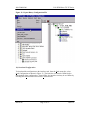
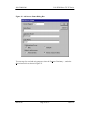
7) Add a Profibus DP Master.
The 5136-PFB-ISA interface card acts as a Profibus DP master to scan up to 96 slaves or
devices. More than 32 slaves require a repeater to achieve the 96 slaves. The interface
card supports up to 244 bytes of input data and 244 bytes of output data per slave. The
interface card supports a total of 16Kbytes input data and 16Kbytes output data for all
slave data. It is permissible to have multiple interface cards in the same host computer.
HA136387
Page 14 of 37
Issue 1.2
AN-COMM-500
5136-PFB-ISA to TU/TC Series
To add a Profibus DP Master from the hierarchical tree view expand the Masters and SST
branch and drag the 5136-PFB-ISA MASTER object to the right hand pane. Do this by
left clicking and holding the left mouse button down anywhere on the 5136-PFB-ISA
MASTER row and dragging it across to the right-hand pane and release the mouse
button. Doing so causes a Master device to be added to the Profibus-DP hierarchical tree
and the SST 5136-PFB-ISA MASTER dialog box to appear where the name, card name,
description, Master Station address, and the scan cycle time under the Parameters tab
may be configured. Figure 9 shows the interface card renamed as ‘SST_5136_PFB’ and
the Master Station address changed to 4. A master device must be added to the
configuration before any slave devices can be added.
Figure 9. Profibus Master and 2 TU1471 Slaves Configured.
HA136387
Page 15 of 37
Issue 1.2
AN-COMM-500
5136-PFB-ISA to TU/TC Series
8) Add Eurotherm TU/TC Series(s) as Slaves.
As with the Profibus master, drag a TU/TC Series object over to the right-hand pane. In
our example a TU Series is added shown as ‘TU Series Thyristor Unit’ in Figure 8 in the
left-hand pane. A TU Series Profibus-DP slave is added to the hierarchical tree and the
TU Series Thyristor Unit properties dialog box shown in Figure 10 appears where the
name, description, address, modules, parameters, and more may be configured.
The Module must be configured which is under the Modules tab. To configure the
Module click on the Modules tab then click the ‘Add’ command button to add the TU
Module under the Modules tab as shown in Figure 10. The single available Module is
named TU in our example.
To add more TU’s to the Profibus network simply drag the TU Series Thyristor Unit
object over to the right-hand pane. Rename it if desired and make sure the slave address
is correct – it auto-increments from the last lowest open address. Figure 9 shows 2 TU
Series renamed to ‘TU1471#1’ and ‘TU1471#2’. The slave station addresses are 10 and
11 respectively as shown by the number followed by a colon just before the name of the
TU Series.
Right clicking on the slave device in the right-hand pane brings up the properties dialog
box.
Figure 10. Properties Dialog Box
HA136387
Page 16 of 37
Issue 1.2
AN-COMM-500
5136-PFB-ISA to TU/TC Series
The GSD file imported in Step 6 defines one (TU/TC supports one module definition
only) or more Module definitions for an automation device. These are shown in the
Available Modules pane under the Modules tab and are required for the configuration of
the slave device. The Module definition in the GSD file defines the Module name, length
of the input and output data and the size of this data – as byte or word in length. This
information is decoded and displayed in the Configured Data Areas under the Modules
tab. Some automation devices have multiple Modules.
The Name column of the Configured Data Areas pane represents the type and the size of
the Module by default. The Description column lists the original name defined in the
GSD file for the selected Module. Some Modules consist of multiple data areas – input
and output in our example.
On the right-hand side of the Modules tab, Module: means the number of modules that
have been configured. In our example, 1 of 1 means the TU/TC Series supports 1
Module. The Input: is the size of the configured input data in bytes. The Output: is the
size of the configured output data in bytes. If the Modular Station check box is checked
modules may be added or removed from the slave device. In this case only one can be
configured.
The Remove command button is used to remove a selected module from the configured
modules list. The name in the Configured Data Areas data must first be selected by
clicking on if the Remove command button is not enabled.
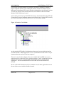
9) Save Configuration
Under the File menu title, select the Save menu item, enter an appropriate file name –
TU1471 was used for this example, in the Save dialog box and select Save. A
subdirectory named Apps was created under the Dlink32 subdirectory to store application
files in this example. See Figure 11.
HA136387
Page 17 of 37
Issue 1.2
AN-COMM-500
5136-PFB-ISA to TU/TC Series
Figure 11. Saved Configuration Files
Note from Figure 11 the TU1471.bss file. This file is needed for the PFBDDEM1 DDE
server configuration. To generate, from the File menu title, select Export Binary as
shown in Figure 12. The file name defaults to the current saved or loaded configuration.
HA136387
Page 18 of 37
Issue 1.2
AN-COMM-500
5136-PFB-ISA to TU/TC Series
Figure 12. Export Binary Configuration File
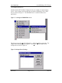
10) Download Configuration
To download the configuration to the interface card, from the Card menu title, select
Load Configuration as shown in Figure 13. The interface card must be Offline before
downloading of the configuration. If not Offline, the interface card may be set Offline by
selecting the Offline menu item from the Card menu title.
HA136387
Page 19 of 37
Issue 1.2
AN-COMM-500
5136-PFB-ISA to TU/TC Series
Figure 13. Load Configuration
The SST Profibus Configuration software will download the saved configuration to the
interface card. If successful, the word CONFIGURED is displayed after the Master in
parenthesis as shown in Figure 14.
HA136387
Page 20 of 37
Issue 1.2
AN-COMM-500
5136-PFB-ISA to TU/TC Series
Figure 14. Interface Card Configured
11) Set Interface Card Online
Again, from the Card menu title, to set interface card Online, select Online as shown in
Figure 15.
Figure 15. Set Interface Card Online
HA136387
Page 21 of 37
Issue 1.2
AN-COMM-500
5136-PFB-ISA to TU/TC Series
If successful, the CONFIGURED is replaced by ONLINE in parenthesis as shown in
Figure 16 and the interface starts scanning the network. At this time both the System
Status and Comms Status LED’s on the interface card should now be solid green in color.
To check the operation of the Profibus network, the DP Monitor software under the
Monitor Utilities folder may be used.
It is not always necessary to go ONLINE at this stage. In particular when using OPC, the
Client side will cause an automatic connect to the interface card. If using DDE, normally
the Client side prompts to start the DDE server if it is not already running.
Figure 16. Interface Card Online
At this point the SST Profibus Configuration software may be exited with the interface
card left ONLINE. What happens now? How is visualization achieved? How do we get
instrument data into and out of the host computer?
There are 3 ways for this to happen. There are available OPC and DDE servers, and
proprietary drivers written for specific software packages. These 3 technologies provide
interface to the majority of popular HMI and application software available in the
marketplace. The next sections show the use of a DDE Server and Wonderware’s
InTouch.
Be sure to check the Eurotherm web site (eurotherm.com) for other application notes on
the use of these servers with the Profibus network.
HA136387
Page 22 of 37
Issue 1.2
AN-COMM-500
5136-PFB-ISA to TU/TC Series
12) Configure DDE Server
Included with the SST Profibus Configurator tools are a number of communications
servers. In this example select from the Servers folder the DP Master Class 1 DDE
Server as shown in Figure 17. The PFB DDE Server is used for Profibus slave
applications.
Figure 17. Starting the PDBDDEM1 Server
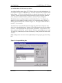
The first step is to select Board Configuration… under the Configure menu title. The
Adapter Board Settings dialog box appears. Select New to add an adapter board
configuration as shown in Figure 18.
Figure 18. Adapter Board Settings
HA136387
Page 23 of 37
Issue 1.2
AN-COMM-500
5136-PFB-ISA to TU/TC Series
The settings for the adapter card may now be entered into the PFBDDE Adapter Card
Settings dialog box as shown in Figure 19. The Registered Boards entry must match the
card name as shown in Figure 2.
Figure 19. PFBDDE Adapter Card Settings
Select the correct baud rate – 12mb is typical, and enter the Station address that matches
that of the address of the 5136_PFB_ISA card entered in step 7. Check the Master check
box and uncheck the Slave check box. Then enter the full path and file name of the
exported binary file from step 9. In this example the full path and file name is:
D:\SST\DLINK32\Apps\TU1471.bss
Make sure to include the file type ‘bss’.
Next, select Topic Definition… under the Configure menu title. The PFBDDE Topic
Definition dialog box appears as shown in Figure 20. In the Names frame, the Topic: is a
reference name that will be used in subsequent steps. Typically there is a Topic for each
TU/TC Series on the Profibus node as the Topic defines the station address, the number
of input and output words, and update rate. The Topic name therefore should be relevant
to the function of the defined station address.
The Adapter Card: is again the name of the 5135_PFB_ISA card from step 1.
HA136387
Page 24 of 37
Issue 1.2
AN-COMM-500
5136-PFB-ISA to TU/TC Series
Figure 20. PFBDDE Topic Definition
In the Topic Configuration frame, the Topic Type Master I/O check box must be enabled.
The I/O Type: set to I/Os, the Slave Station Number set to match the address of the slave
TU/TC, the Format: set to WORD, and the Length: set to match the total length of the
input and output registers from the configuration. The Update may be changed from the
default of 1 second if either faster or slower update times from the DDE server are
desired.
The DDE Server Settings… menu item under the Configure menu title typically does not
require any modification. Be sure to visit the last menu item under the Configure menu
title, Save Configuration. The default file name is Pfbddem1.cfg.
The SSConfig menu item under the Direct Link Registry menu title typically does not
require any changes. Figure 21 shows the results of pressing the Properties command
button for the Driver250 card. Again, this information should match that configured in
step 1 and not require any changes.
HA136387
Page 25 of 37
Issue 1.2
AN-COMM-500
5136-PFB-ISA to TU/TC Series
Figure 21. PFBDDE Direct-Link Card Configuration
Figure 22 shows the Direct-Link Modules configuration. For each 5136_PFB_ISA card
in the PC, a module file named pciprofi.ss1 or pfbprofi.ss1 is required. In this example,
the PC has 1 ISA card so the pciprofi file has been deleted. The Module ID for the
5136_PFB_ISA card is BB01 as shown in Figure 22 – do not change.
The settings under Driver and General tabs do not require any changes unless it is resired
to manually start the PFBDDE server rather than automatically. This setting is under the
Driver tab.
HA136387
Page 26 of 37
Issue 1.2
AN-COMM-500
5136-PFB-ISA to TU/TC Series
Figure 22. PFBDDE Direct-Link Module Configuration
This completes the settings for the PFBDDE server.
HA136387
Page 27 of 37
Issue 1.2
AN-COMM-500
5136-PFB-ISA to TU/TC Series
13) Configuring InTouch Tags
This section does not go into detail on configuring and creating a display(s) in InTouch.
It is assumed that the expertise necessary for that is available. Rather, this section covers
the basics in the configuration of the Access names and the creation of input and output
tags.
After creating a new application, Access names are necessary to be able to reference the
Topic names in created step 12. Figure 23 shows how to access the Access Names…
menu item. There is an Access Name for each Topic used.
Figure 23. Access Names… Menu Item
From the Access Names dialog box select the Add… command button to create a new
Access Name. The Add Access Names dialog box appears as shown in Figure 24. Enter
into the Access Name: text box a name used to reference the Application and Topic that
are entered in next. Typically the access name is the same as the topic name though it
does not need to be. The Application Name: is PFBDDEM1. Enter into the Topic Name:
text box the name of a topic created from step 12.
HA136387
Page 28 of 37
Issue 1.2
AN-COMM-500
5136-PFB-ISA to TU/TC Series
Figure 24. Add Access Names Dialog Box
To create tags for read and write purposes select the Tagname Dictionary… under the
Special menu title as shown in Figure 25.
HA136387
Page 29 of 37
Issue 1.2
AN-COMM-500
5136-PFB-ISA to TU/TC Series
Figure 25. Tagname Dictionary Menu Item
Figure 26 shows the tagname definition dialog box. Important fields of note are:
Type: … which should be set to either I/O Real or I/O Integer. Some parameters in the
Series 2000 have implicit decimal point positions or IEEE 4 byte single precision modbus
addresses that necessitate the need for I/O Real data types.
Access Name: … click on the Access Name command button to select the Access Name
associated with the Topic and therefore the station address of the TU/TC for which the
Item is being configured.
Item: … to address a register in the 5136_PFB_ISA card, a pre-defined format must be
used for each item.
HA136387
Page 30 of 37
Issue 1.2
AN-COMM-500
5136-PFB-ISA to TU/TC Series
An item format includes: item type, register within configured topic, then optional bit
number and display format. The first letter represents the item type. The item names are
not case sensitive, so capital letters could also have been used.
q
i
d
p
means the item is type of an output from Master
means the item is type of an input to Master
means the item is type of diagnostic to Master
means the item is type of parameter from Master
The register is the number within configured length of the parent topic and follows item
type. As the length was defined as a Word in the Topic definition, one separates each
item register. This is shown in Table 7.
The next part of the item name is the optional bit offset separated with a forward slash
("/"). Value of the bit can be (0-7) when topic data configured as BYTE and (0-15) when
topic data configured as a WORD.
The last part of the item name is the optional display format. These qualifiers must be
separated from the register by a space.
S or SIGNED treats the value as a signed 8-bit for BYTE FORMAT number (-128 to
127) or 16-bit for WORD FORMAT number (-32768 to 32767)
4 or 4BCD
3 or 3BCD
the value is treated as a 4-digit BCD number (0 to 9999)
the value is treated as a 3-digit BCD number (0 to 999)
For integer format of the item no bit number is to be defined nor slash ("/") character
present.
HA136387
Page 31 of 37
Issue 1.2
AN-COMM-500
5136-PFB-ISA to TU/TC Series
Figure 26. Tagname Definition
For our example Table 7 shows the Tag names and Item names for the 4 input and 4
ouput registers.
Table 7. Example Item Definition
Tagname:
RZ1MV
RZ1OP
RZ1LV
RZ1LC
WZ1CMD
WZ1RS1
WZ1RS2
WZ1VAL
HA136387
Item:
i0
i1
i2
i3
o0
o1
o2
o3
Description
Read Zone 1 Measured Value
Read Zone 1 Output Power
Read Zone 1 Load Voltage
Read Zone 1 Load Current
Write Zone 1 Command/Parameter Address
Write Zone 1 Reserved 1
Write Zone 1 Reserved 2
Write Zone 1 Value
Page 32 of 37
Issue 1.2
AN-COMM-500
5136-PFB-ISA to TU/TC Series
14) Using Demand Data in the TU/TC Series
The 4 output words defined in the GSD file do not have TU/TC parameter addresses
associated with them. These output words are instead reserved for demand data or dataexchange purposes – a request/response scenario. This allows parameters to be read
which are not defined in the GSD file or any writeable parameter to be written.
In other words, by entering a command, a parameter address and optionally a parameter
value for a write command, a request to read or write any addressable parameter in the
TU/TC Series may be made. Table 8 details the 4-word output structure.
Table 8. Demand Data Structure
Word
0
1
Byte (or Octet)
0
1
2
Reserved
Command &
Parameter Address
2
3
3
4
5
6
Value
7
The command word (bytes 0 and 1) is further broken down as shown in Table 9. The
valid commands are shown in Table 10.
Table 9. Word 0 Command/Parameter Address
Byte
0
Bit
15 14 13 12
Command
1
11 10
Reserved
9
8
7
6
5
4
Parameter Address
3
2
1
0
Whenever the command becomes a non-zero value indicating demand data, the input or
read words defined in the GSD file are replaced by the response to the demand data
request. The mapping of the read registers duplicates that of the 4 output words though
the meaning of the command is different. For example, if an invalid request is made the
hex value 70 would be returned in the first byte of the input words.
For those configurations where more than 4 input words are defined the values of all
input words greater than 4 is 0.
HA136387
Page 33 of 37
Issue 1.2
AN-COMM-500
5136-PFB-ISA to TU/TC Series
Table 10. Valid Demand Data Commands
Command
0
1
2
7
Request (Outputs)
No Command
Read Request
Write Request
N/A
Reply (Inputs)
N/A
Ack Read
Ack Write
Reject Request
In the case of a request error, the command field in the first byte (0th byte) of the input
word contains the value 7 while the value field in the 6th byte contains the error code
value. Error codes are shown in the Table 11 below.
Table 11. Demand Data Error Codes
Error
Code
0
1
2
3
4
5
Description
Invalid Parameter Number
RO Parameter (Write Request)
Data >0x7FFF
WO Parameter (Read Request)
Not 8 Bytes in the Configuration
Command not Valid for this Unit
By way of 4 examples below are shown how to read and write using demand data. All
values are shown in hex. Again, note that the input registers are used for the reply.
1) Read Process Value (PV) of TU channel 1 – address 04 (0x04). Here 03 E8
corresponds to a PV of 100.0)
HA136387
Request
WZ1CMD
10 04
WZ1RS1
00 00
WZ1RS2
00 00
WZ1VAL
00 00
Reply
RZ1MV
10 04
RZ1OP
00 00
RZ1LV
00 00
RZ1LC
03 E8
Page 34 of 37
Issue 1.2
AN-COMM-500
5136-PFB-ISA to TU/TC Series
2) Read Power Demand (OP) of TU channel 3 – address 35 (0x23). Here 00 F5
corresponds to an OP of 24.5
Request
WZ1CMD
10 23
WZ1RS1
00 00
WZ1RS2
00 00
WZ1VAL
00 00
Reply
RZ1MV
10 23
RZ1OP
00 00
RZ1LV
00 00
RZ1LC
00 F5
3) Write Local Setpoint (SL) of TU channel 1 – address 1 (0x01). Here 01 F4
corresponds to a SL of 50.0.
Request
WZ1CMD
20 01
WZ1RS1
00 00
WZ1RS2
00 00
WZ1VAL
01 F4
Reply
RZ1MV
20 01
RZ1OP
00 00
RZ1LV
00 00
RZ1LC
01 F4
4) Write Current Limit Setpoint (CL) of TU channel 4 – address 33 (0x21). Here 02 EE
corresponds to a CL of 75.0.
Request
WZ1CMD
20 21
WZ1RS1
00 00
WZ1RS2
00 00
WZ1VAL
02 EE
Reply
RZ1MV
20 21
RZ1OP
00 00
RZ1LV
00 00
RZ1LC
02 EE
The parameter addresses may be found in the following manuals:
TU Series: Digital communications for TU range thyristor units; Communications
manual; Part No. HA173688, Issue 2 or greater
TC Series: Three phase power thyristor unit with digital communications; User Manual;
Part No. HA173941, Issue 2 or greater
HA136387
Page 35 of 37
Issue 1.2
AN-COMM-500
5136-PFB-ISA to TU/TC Series
15) Problems
No Communications:
• Check the wiring carefully, paying particular attention to the continuity of the A and B
connections to the interface card. Ensure that the correct terminals have been wired to.
• Ensure that a Profibus Communication board is installed. The Model number should
include the CCC and PFB option. It can be identified by the PROFIBUS legend on
the CPU on the Communication board and the Profibus interface daughter-board that
plugs into the Communication board.
• Check that the Node Address set by the jumpers on the TU/TC Series Communication
board is correct for the interface card configuration in use.
• Ensure that the interface card is correctly configured and the configuration has been
downloaded correctly to the Profibus master.
• Verify the GSD file in use is correct by loading it into the SST Profibus Configuration
tool again. This will check the format. Verify that no output word addresses have
been defined in the GSD file.
• Verify that the maximum line length for the baud rate in use is not exceeded (see table
4).
• Ensure that the last device (not necessarily a TU/TC Series) in the network segment is
correctly terminated (see wiring diagram).
• Ensure that no devices other than those at the end of a segment have termination
networks fitted.
• If possible, replace faulty device with a duplicate and retest.
HA136387
Page 36 of 37
Issue 1.2
AN-COMM-500
5136-PFB-ISA to TU/TC Series
Notes:
HA136387
Page 37 of 37
Issue 1.2