1
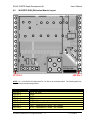
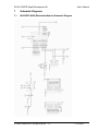
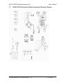
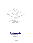
RK-Wi.232DTS User’s Manual
Rev 1.0.3
207 Industrial Blvd
Moore, OK 73170
405-794-7730
© 2004 Radiotronix Inc, all rights reserved
-i-
RK-Wi.232DTS Rapid Development Kit
User’s Manual
Document Control
Created By
Engineering Review
Marketing Review
Approved Engineering
Approved - Marketing
Gordon Hudson
5/17/04
Revision History
Revision
1.0.0
1.0.1
1.0.2
1.0.3
Author
GWH
GWH
GWH
TRM
Date
5/17/04
5/27/04
6/17/04
11/30/04
© 2002-4 Radiotronix Inc, all rights reserved
Description
Document Created
Added PCB Layouts and Schematics
Updated PCB Layouts and Schematics
Corrected RK-Wi.232DTS Schematic
-1-
12/14/2004
RK-Wi.232DTS Rapid Development Kit
User’s Manual
Table of Contents
1
Description ...............................................................................................................................3
2
RApid Development Kit Setup .................................................................................................3
3
Using the RK-Wi.232DTS Evaluation Software.......................................................................4
3.1
COM Port Setup and Selection. ..................................................................................... 4
3.2
Wireless Chat Page. ...................................................................................................... 4
3.3
Non-Volatile Register Page............................................................................................ 5
3.4
Volatile Register Page.................................................................................................... 5
4.
Using the Evaluation Software.................................................................................................6
4.1
Setting Register Values.................................................................................................. 6
4.2
Transceiver Mode........................................................................................................... 6
4.3
Transmit Diagnostic. ...................................................................................................... 6
4.4
Receive Diagnostic. ....................................................................................................... 6
5
Notes........................................................................................................................................7
5.1
Microsoft Windows / Hilgraeve HyperTerminal. ............................................................. 7
5.2
Loopback Mode.............................................................................................................. 7
6
PCB Layout Diagrams .............................................................................................................8
6.1
RK-Wi.232DTS Evaluation (Rapid Development) Board Layout ................................... 8
6.2
Wi.232DTS EVM (EValuation Module) Layout .............................................................. 9
7
Schematic Diagrams..............................................................................................................11
7.1
Wi.232DTS EVM (EValuation Module) Schematic Diagram........................................ 11
7.2
RK-Wi.232DTS Evaluation (Rapid Development) Schematic Diagram. ...................... 12
8
NOTES...................................................................................................................................13
© 2002-4 Radiotronix Inc, all rights reserved
-2-
12/14/2004
RK-Wi.232DTS Rapid Development Kit
User’s Manual
1 Description
The RK-Wi.232DTS is a rapid-development/evaluation kit for the Wi.232DTS data transceiver.
Included in the kit is:
•
1-Rapid Development Case.
•
1-Rapid Development Utility and Documentation CD.
•
2-Wi.232DTS Rapid Development Boards.
•
2-Wi.232DTS Transceiver Modules, mounted on EVM’s*.
•
2-900 MHz antennas.
•
2-RS-232 cables.
•
2-USB cables.
•
6-AAA batteries.
•
Startup Guide.
•
An EVM is a Wi.232DTS module pre-mounted on a small PCB with onboard antenna connector
and power supply regulator.
2 RApid Development Kit Setup
•
Insert the AAA batteries into the evaluation PCB, observing the correct polarity.
•
Insert an EVM into one of the evaluation boards, observing the correct orientation (see later in
this document). The correct orientation of the EVM is with the antenna connector closest to the
edge of the evaluation board. Make sure the module is seated fully and correctly.
•
Insert the other EVM into the other evaluation board, also observing the correct polarity.
•
Connect antennas to EVM’s.
•
Connect evaluation boards to computers. If using USB communications, populate USB jumpers
and remove RS-232 jumpers. If using RS-232 communications, populate RS-232 jumpers and
remove USB jumpers.
•
Install the RK-Wi.232DTS Windows software. If already installed, skip this step.
•
Run the RK-Wi.232DTS software, select 2400 baud operation and navigate to the “Wireless
Chat” tab.
•
Power-On both evaluation boards, verifying that the version/copyright information is echoed to the
screen from both modules.
•
Chat back and forth between evaluation boards, verifying that serial and RF communications are
successful.
•
IMPORTANT NOTE FOR HYPERTERMINAL USERS: See section 4.1
© 2002-4 Radiotronix Inc, all rights reserved
-3-
12/14/2004
RK-Wi.232DTS Rapid Development Kit
User’s Manual
3 Using the RK-Wi.232DTS Evaluation Software
The software supplied with the RK-Wi.232DTS RadKit is used to read and set the volatile and non-volatile
registers with the Wi.232DTS module. Refer to the Wi.232DTS Users Manual for more information on the
register settings.
3.1
COM Port Setup and Selection.
Upon starting the RK-Wi.232DTS evaluation software, you will be
presented with a COM port selection dialog box. If you are using the
USB interface, make sure that the evaluation board is already
connected to the computer via the USB cable before you start the
software. This will ensure that the virtual COM port which is assigned
to the USB to UART bridge controller by Windows is visible in the
COM port selection list.
The first time you start the RK-Wi.232DTS evaluation software, the
Baud Rate should be left at 2400 baud, since this is the factory default
baud rate setting for the module.
Tip: There is no way for the RK-Wi.232DTS evaluation software to
detect which baudrate the module is set to. If you have changed the
Non-Volatile Data Rate register, you will have to select the baud rate
you set this register to when you start the RK-Wi.232DTS evaluation
software.
3.2
Wireless Chat Page.
The Wireless Chat page in the RK-Wi.232DTS evaluation software demonstrates the capability of the
Wi.232 to be used as a wireless communications link. The Rapid Development kit works as a wireless
chat link with no register changes required, out of the box.
To Use Wireless Chat:
Type a message in the
lower text field and press
Enter. The text you typed
will be displayed on the
remote system, prefixed
with a Node Identifier if
you specified one.
© 2002-4 Radiotronix Inc, all rights reserved
-4-
12/14/2004
RK-Wi.232DTS Rapid Development Kit
3.3
User’s Manual
Non-Volatile Register Page.
The Non-Volatile Register
page in the evaluation
software allows you to
change the default
settings which will be
loaded when the module
is powered on.
It is important to note that
data rates in excess of
19.2kbps cannot be
achieved in LP mode due
to bandwidth limitations.
Tip: If you change the
Non-Volatile Data Rate
setting, you will have to
select the baud rate you
set this register to when
you start the RKWi.232DTS evaluation
software.
3.4
Volatile Register Page
In this page, you can
change the Volatile
settings of the module.
Values programmed into
these registers are lost of
power-down.
The page also provides a
means of switching the
receiver and transmitter
on and off, setting receive
and transmit channels,
transceiver mode and
modulation settings.
It is important to note that
data rates in excess of
19.2kbps cannot be
achieved in LP mode due
to bandwidth limitations.
© 2002-4 Radiotronix Inc, all rights reserved
-5-
12/14/2004
RK-Wi.232DTS Rapid Development Kit
4.
Using the Evaluation Software.
4.1
Setting Register Values.
User’s Manual
On both the Volatile and Non-Volatile pages, the registers are labeled by function. To set a register value,
select the value from the options available for that register and click the “Write” button. To perform a read
of that register, simply click the “Read” button. Descriptions of the register functions can be found in the
Wi.232DTS Users Manual.
4.2
Transceiver Mode.
This selects the mode of both the transmitter and receiver. The mode is not set until “Set TX Diag” or “Set
RX Diag” is pressed.
4.3
Transmit Diagnostic.
Transmit Diagnostic consists of four radio buttons which select the transmit channel. Low, Mid and High
are quick reference buttons which can be used to select the lowest, the middle, or the highest channel.
Any specific channel can be selected by using the controls below the “Set RX Diag” button.
The “Set RX Diag” button switches on the receiver using the channel and mode set up using the channel
selector and transceiver mode controls.
If a “…1010101010101…” bit pattern is being received at the frequency and baudrate set up in the
relevant registers, a BER test will be performed and the number and percent of bit errors is displayed in
the panel otherwise populated with the text “Unknown”.
4.4
Receive Diagnostic.
Receive Diagnostic consists of four radio buttons which select the transmit channel. Low, Mid and High
are quick reference buttons which can be used to select the lowest, the middle, or the highest channel.
Any specific channel can be selected by using the controls above the “Set TX Diag” button.
The “Set TX Diag” button switches on the transmitter using the channel and mode set up using the
channel selector and transceiver mode controls.
A “…1010101010101…” bit pattern is transmitted for bit error testing with another system. This is not a
true pseudo-random sequence BER test.
© 2002-4 Radiotronix Inc, all rights reserved
-6-
12/14/2004
RK-Wi.232DTS Rapid Development Kit
5
Notes
5.1
Microsoft Windows / Hilgraeve HyperTerminal.
User’s Manual
The RK-Wi.232DTS Evaluation Kit can be used with HyperTerminal to receive and transmit RS-232 data
and send files using file transfer protocols such as ZMODEM. HyperTerminal and many other terminal
programs assert RTS by default. On the evaluation board, the RTS line is tied to the CMD pin on the
module. When the CMD pin is held low, which is the case when the RTS line is asserted, the module will
be placed in command mode.
In command mode, all UART data sent to the module will be interpreted as commands and will NOT be
sent to the RF engine for transmission. Additionally, if an evaluation board is switched on in the presence
of an asserted RTS line, it will perform a full hardware and flash reset to the factory defaults.
To use the evaluation board with HyperTerminal or other terminal program, you must first remove the
jumpers from pins 7+8 of JP2, if you are using an RS-232 connection to your PC, or JP3, if you are using
a USB connection to your PC. Removing this jumper will disconnect the RTS line from the CMD pin on
the module, allowing normal operation.
5.2
Loopback Mode.
The RK-Wi.232DTS kit can be operated in a loopback mode by configuring the COM jumpers in such a
way as to link together the TXD and RXD lines to and from the module in the remote evaluation board.
Using this mode, the user can send data from their local evaluation board and have it re-transmitted back
to them by the remote evaluation board. The maximum baud rate allowed in loopback mode is 38400
baud for point to point communications only.
Loopback mode using the RS232 jumpers:
© 2002-4 Radiotronix Inc, all rights reserved
-7-
12/14/2004
RK-Wi.232DTS Rapid Development Kit
User’s Manual
6
PCB Layout Diagrams
6.1
RK-Wi.232DTS Evaluation (Rapid Development) Board Layout
© 2002-4 Radiotronix Inc, all rights reserved
-8-
12/14/2004
RK-Wi.232DTS Rapid Development Kit
6.2
User’s Manual
Wi.232DTS EVM (EValuation Module) Layout
JP1 Pin 1
JP2 Pin 1
NOTE: Pin 1 of the EVM’s JP2 aligns with Pin 1 of JP6 on the evaluation board. The following table lists
the pin numbers and their assignments
Pin Name
JP2 Pin 1
JP2 Pin 2
JP2 Pin 3
JP2 Pin 4
JP2 Pin 5
JP2 Pin 6
JP2 Pin 7
JP2 Pin 8
Pin Description
4V to 12V Vdd
RxD0
TxD0
CTS0
CMD (Active Low)
RxD1 – Reserved for Future – No Connect
TxD1 – Reserved for Future – No Connect
RTS1 – Reserved for Future – No Connect
© 2002-4 Radiotronix Inc, all rights reserved
-9-
12/14/2004
RK-Wi.232DTS Rapid Development Kit
Pin Name
JP2 Pin 9
JP2 Pin 10
JP2 Pin 11
JP2 Pin 12
JP1 Pin 1
JP1 Pin 2
JP1 Pin 3
JP1 Pin 4
JP1 Pin 5
JP1 Pin 6
JP1 Pin 7
JP1 Pin 8
JP1 Pin 9
JP1 Pin 10
JP1 Pin 11
JP1 Pin 12
User’s Manual
Pin Description
DTR1 – Reserved for Future – No Connect
DTR1* - Reserved for Future – No Connect
GND
GND
GND
GND
AD1 – Reserved for Future – No Connect
AD0 – Reserved for Future – No Connect
RSSI – Reserved for Future – No Connect
PD5 – Reserved for Future – No Connect
PD4 – Reserved for Future – No Connect
PD3 – Reserved for Future – No Connect
PD2 – Reserved for Future – No Connect
PD1 – Reserved for Future – No Connect
GND
GND
Table 1, EVM Module Pinout
© 2002-4 Radiotronix Inc, all rights reserved - 10 -
12/14/2004
RK-Wi.232DTS Rapid Development Kit
7
Schematic Diagrams
7.1
Wi.232DTS EVM (EValuation Module) Schematic Diagram
© 2002-4 Radiotronix Inc, all rights reserved - 11 -
User’s Manual
12/14/2004
RK-Wi.232DTS Rapid Development Kit
7.2
User’s Manual
RK-Wi.232DTS Evaluation (Rapid Development) Schematic Diagram.
© 2002-4 Radiotronix Inc, all rights reserved - 12 -
12/14/2004
RK-Wi.232DTS Rapid Development Kit
8
User’s Manual
NOTES
© 2002-4 Radiotronix Inc, all rights reserved - 13 -
12/14/2004