1
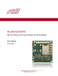
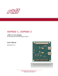
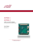
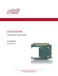
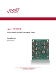
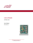
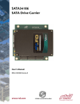
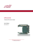
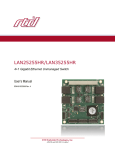
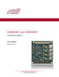
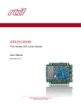
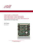
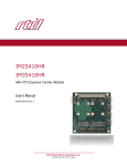
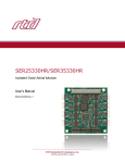
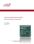
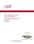
BRG2110 PCI Express to PCI Bridge User’s Manual BDM-610020084 Rev. A RTD Embedded Technologies, Inc. AS9100 and ISO 9001 Certified RTD Embedded Technologies, Inc. 103 Innovation Boulevard State College, PA 16803 USA Telephone: 814-234-8087 Fax: 814-234-5218 www.rtd.com [email protected] [email protected] Revision History Rev A Initial Release Advanced Analog I/O, Advanced Digital I/O, aAIO, aDIO, a2DIO, Autonomous SmartCal, “Catch the Express”, cpuModule, dspFramework, dspModule, expressMate, ExpressPlatform, HiDANplus, “MIL Value for COTS prices”, multiPort, PlatformBus, and PC/104EZ are trademarks, and “Accessing the Analog World”, dataModule, IDAN, HiDAN, RTD, and the RTD logo are registered trademarks of RTD Embedded Technologies, Inc (formerly Real Time Devices, Inc.). PS/2 is a trademark of International Business Machines Inc. PCI, PCI Express, and PCIe are trademarks of PCI-SIG. PC/104, PC/104-Plus, PCI-104, PCIe/104, PCI/104-Express and 104 are trademarks of the PC/104 Embedded Consortium. All other trademarks appearing in this document are the property of their respective owners. Failure to follow the instructions found in this manual may result in damage to the product described in this manual, or other components of the system. The procedure set forth in this manual shall only be performed by persons qualified to service electronic equipment. Contents and specifications within this manual are given without warranty, and are subject to change without notice. RTD Embedded Technologies, Inc. shall not be liable for errors or omissions in this manual, or for any loss, damage, or injury in connection with the use of this manual. Copyright © 2010 by RTD Embedded Technologies, Inc. All rights reserved. RTD Embedded Technologies, Inc. | www.rtd.com iii BRG2110 User’s Manual Table of Contents 1 2 3 4 5 Introduction 6 1.1 Product Overview........................................................................................................................................................................ 6 1.2 Board Features ........................................................................................................................................................................... 6 1.3 Ordering Information ................................................................................................................................................................... 6 1.4 Contact Information .................................................................................................................................................................... 7 1.4.1 Sales Support 7 1.4.2 Technical Support 7 Specifications 8 2.1 Operating Conditions .................................................................................................................................................................. 8 2.2 Electrical Characteristics ............................................................................................................................................................ 8 Board Connection 9 3.1 Board Handling Precautions ....................................................................................................................................................... 9 3.2 Physical Characteristics .............................................................................................................................................................. 9 3.3 Connectors and Jumpers .......................................................................................................................................................... 10 3.3.1 External I/O Connectors 10 3.3.2 Bus Connectors 10 CN1(Top) & CN2(Bottom): PCIe Connector 10 CN16: PCI Connector 10 3.3.3 Jumpers 11 JP1: -12V Control 11 JP300: PCI Vio Select 11 3.4 Steps for Installing .................................................................................................................................................................... 12 IDAN Connections 13 4.1 Module Handling Precautions ................................................................................................................................................... 13 4.2 Physical Characteristics ............................................................................................................................................................ 13 4.3 Connectors................................................................................................................................................................................ 13 4.3.1 External I/O Connectors 13 4.3.2 Bus Connectors 13 CN1(Top) & CN2(Bottom): PCIe Connector 13 CN16: PCI Connector 14 4.4 Steps for Installing .................................................................................................................................................................... 14 Functional Description 15 5.1 Block Diagram........................................................................................................................................................................... 15 5.2 PCIe to PCI Bridge ................................................................................................................................................................... 15 5.2.1 PCI Bus Masters 15 5.2.2 Wake from PCI Devices 15 5.2.3 Compatibility with PCI-to-ISA Bridges (BRG17088) 15 5.3 Power ........................................................................................................................................................................................ 15 5.3.1 -12V Power Supply 16 6 Troubleshooting 17 7 Additional Information 18 8 7.1 PC/104 Specifications ............................................................................................................................................................... 18 7.2 PCI and PCI Express Specification .......................................................................................................................................... 18 Limited Warranty RTD Embedded Technologies, Inc. | www.rtd.com 19 iv BRG2110 User’s Manual Table of Figures Figure 1: BRG2110AHR (Above CPU) ..................................................................................................................................................................... 6 Figure 2: BRG2110BHR (Below CPU) ..................................................................................................................................................................... 6 Figure 3: Board Dimensions ..................................................................................................................................................................................... 9 Figure 4: Board Connections .................................................................................................................................................................................. 10 Figure 5: Example 104™Stack ............................................................................................................................................................................... 12 Figure 6: IDAN Dimensions .................................................................................................................................................................................... 13 Figure 7: Example IDAN System ............................................................................................................................................................................ 14 Figure 8: BRG2110 Block Diagram ........................................................................................................................................................................ 15 Table of Tables Table 1: Ordering Options ........................................................................................................................................................................................ 6 Table 2: Operating Conditions .................................................................................................................................................................................. 8 Table 3: Electrical Characteristics ............................................................................................................................................................................ 8 Table 4: JP1 Settings .............................................................................................................................................................................................. 11 Table 5: JP300 Settings .......................................................................................................................................................................................... 11 RTD Embedded Technologies, Inc. | www.rtd.com v BRG2110 User’s Manual 1 Introduction 1.1 Product Overview The BRG2110 is designed to provide a PCI Express (PCIe) to PCI Bridge. It uses a PCIe x1 link to interface to the CPU module, and provides a full PCI interface to PC/104-Plus and PCI-104 peripheral cards. This allows the addition of a PCI bus segment to the 104™ system which can support four more peripheral cards. It is compatible with all PCI Express cpuModules. 1.2 Board Features 1.3 PCI Express (PCIe) x1 Upstream Interface to CPU PCI Downstream Interface to Peripheral Cards Power rails (+5V, +3.3V, +12V) connected between the PCIe and PCI bus PCI Express Bus: o Provides 2.5 Gbps in each direction o Single lane and single Virtual Channel operation Compatible with multi-Virtual Channel chipsets o Packetized serial traffic with PCI Express Split Completion protocol o Data Link Layer Cyclic Redundancy Check (CRC) generator and checker o Automatic Retry of bad packets o In-band interrupts and messages o Message Signaled Interrupt (MSI) support PCI Bus: o 32-bit, 33 MHz PCI Bus o PCI Master Controller allows PCI Express access to PCI Target Devices o PCI Target Controller allows full transparent access to PCI Express resources o Message Signaled Interrupt (MSI) support o Legacy Interrupt support o Four Bus Masters o Jumper selectable VIO 5V or 3.3V signal level o Jumper selectable -12V @ 500 mA power supply to PCI bus Ordering Information The BRG2110 is available with the following options: Table 1: Ordering Options Part Number BRG2110AHR BRG2110BHR IDAN-BRG2110AHRS IDAN-BRG2110BHRS Description PCIe to PCI Bridge for Above the CPU PCIe to PCI Bridge for Below the CPU PCIe to PCI Bridge for Above the CPU in IDAN enclosure PCIe to PCI Bridge for Below the CPU in IDAN enclosure Figure 1: BRG2110AHR (Above CPU) Figure 2: BRG2110BHR (Below CPU) The Intelligent Data Acquisition Node (IDAN™) building block can be used in just about any combination with other IDAN building blocks to create a simple but rugged 104™ stack. This module can also be incorporated in a custom-built RTD HiDAN™ or HiDANplus High Reliability Intelligent Data Acquisition Node. Contact RTD sales for more information on our high reliability systems. RTD Embedded Technologies, Inc. | www.rtd.com 6 BRG2110 User’s Manual 1.4 Contact Information 1.4.1 SALES SUPPORT For sales inquiries, you can contact RTD Embedded Technologies sales via the following methods: Phone: E-Mail: 1.4.2 1-814-234-8087 [email protected] Monday through Friday, 8:00am to 5:00pm (EST). TECHNICAL SUPPORT If you are having problems with you system, please try the steps in the Troubleshooting section of this manual. For help with this product, or any other product made by RTD, you can contact RTD Embedded Technologies technical support via the following methods: Phone: E-Mail: 1-814-234-8087 Monday through Friday, 8:00am to 5:00pm (EST). [email protected] RTD Embedded Technologies, Inc. | www.rtd.com 7 BRG2110 User’s Manual 2 Specifications 2.1 Operating Conditions Table 2: Operating Conditions Symbol Vcc5 Vcc3 Vcc12 Vcc-12 Ta Ts RH MTBF 2.2 Parameter 5V Supply Voltage 3.3V Supply Voltage 12V Supply Voltage -12V Supply Voltage Operating Temperature Storage Temperature Relative Humidity Mean Time Before Failure Test Condition Non-Condensing 23C Min 4.75 n/a n/a n/a -40 -55 0 TBD Max 5.25 n/a n/a n/a +85 +125 90% Unit V V V V C C % Hours Min Max Unit W mA V mA A A A Electrical Characteristics Table 3: Electrical Characteristics Symbol P Icc5 VOUT12 IOUT12 IBUS5 IBUS3.3 IBUS12 Parameter Power Consumption 5V Input Supply Current -12V Output Supply Voltage -12V Output Supply Current 5V Current between buses 3.3V Current between buses 12V Current between buses VIH3.3 VIL3.3 VIH5 VIL5 IIL IOZ VOH3.3 VOL3.3 VOH5 VOL5 PCI 3.3V Input High Voltage PCI 3.3V Input Low Voltage PCI 5V Input High Voltage PCI 5V Input Low Voltage PCI Input Leakage PCI Hi-Z Leakage PCI 3.3V Output High Voltage PCI 3.3V Output Low Voltage PCI 5V Output High Voltage PCI 5V Output Low Voltage Test Condition Vcc5 = 5.0V Active JP1 = 1-2 (ON) JP1 = 1-2 (ON) PCI Bus JP300 = 1-2 (3.3V) JP300 = 1-2 (3.3V) JP300 = 2-3 (5V) JP300 = 2-3 (5V) 0<VI<VIO 0<VI<VIO JP300 = 1-2 (3.3V), IOUT = -0.5mA JP300 = 1-2 (3.3V) , IOUT = 1.5mA JP300 = 2-3 (5V) , IOUT = -12mA JP300 = 2-3 (5V) , IOUT = 12mA PCIe Bus Differential Output Voltage DC Differential TX Impedance Differential Input Voltage DC Differential RX Impedance Electrical Idle Detect Threshold RTD Embedded Technologies, Inc. | www.rtd.com -13.2 1.65 0 2.0 0 -10 3.3 0.7 5.5 0.8 10 10 0.4 V V V V uA uA V V V V 1.2 116.9 3.3 115.8 173 V Ω V Ω mV 2.97 0.33 2.4 0.8 95.2 0.175 92.7 61 8 0.5 100 -10.8 500 8.0 3.0 1.0 BRG2110 User’s Manual 3 Board Connection 3.1 Board Handling Precautions To prevent damage due to Electrostatic Discharge (ESD), keep your board in its antistatic bag until you are ready to install it into your system. When removing it from the bag, hold the board at the edges, and do not touch the components or connectors. Handle the board in an antistatic environment, and use a grounded workbench for testing and handling of your hardware. 3.2 Physical Characteristics Weight: Approximately 55 g (0.12 lbs.) Dimensions: 90.17 mm L x 95.89 mm W (3.550 in L x 3.775 in W) Figure 3: Board Dimensions RTD Embedded Technologies, Inc. | www.rtd.com 9 BRG2110 User’s Manual 3.3 Connectors and Jumpers CN16: PCI Connector JP1: -12V Control JP300: PCI Vio Select CN1 & CN2: PCIe Connector Figure 4: Board Connections 3.3.1 EXTERNAL I/O CONNECTORS There are no external I/O connectors on the BRG2110. 3.3.2 BUS CONNECTORS CN1(Top) & CN2(Bottom): PCIe Connector The PCIe connector is the connection to the system CPU. The position and pin assignments are compliant with the PCI/104-Express Specification. (See PC/104 Specifications on page 18) The BRG2110 is a “Universal” board, and can connect to either a Type 1 or Type 2 PCIe/104 connector. CN16: PCI Connector The PCI connector is the connection to PCI peripheral modules. The position and pin assignments are compliant with the PCI/104-Express Specification. (See PC/104 Specifications on page 18) RTD Embedded Technologies, Inc. | www.rtd.com 10 BRG2110 User’s Manual 3.3.3 JUMPERS On all jumpers, pin 1 is designated by a thick white silkscreen line, and a square pad on the PCB. JP1: -12V Control JP1 is used to enable and disable the -12V power supply to the PCI bus. See the “-12V Power Supply” section on page 16 for more details. Table 4: JP1 Settings Setting 1-2 2-3 Description BRG2110 supplies -12V to the PCI bus. BRG2110 does not supply -12V to the PCI bus. (factory default) NOTE: When the BRG2110 is supplying -12V to the PCI bus (i.e. JP1 = 1-2), there must not be any other -12V power supplies on that PCI bus segment. JP300: PCI Vio Select JP300 is used to set the voltage of the VIO pins on the PCI bus. It does not change the actual signal level that the BRG2110 uses. When selecting a VIO voltage, be sure that all of the PCI peripheral cards on the PCI bus of the BRG2110 are compatible with the selected voltage. Table 5: JP300 Settings Setting 1-2 2-3 Description PCI bus VIO pins set to 3.3V (factory default) PCI bus VIO pins set to 5V RTD Embedded Technologies, Inc. | www.rtd.com 11 BRG2110 User’s Manual 3.4 Steps for Installing 1. 2. 3. 4. 5. 6. 7. 8. 9. 10. 11. 12. Always work at an ESD protected workstation, and wear a grounded wrist-strap. Turn off power to the PC/104 system or stack. Select and install stand-offs to properly position the module on the stack. Remove the module from its anti-static bag. Check that pins of the bus connector are properly positioned. Check the stacking order; make sure all of the busses used by the peripheral cards are connected to the cpuModule. Hold the module by its edges and orient it so the bus connector pins line up with the matching connector on the stack. Gently and evenly press the module onto the PC/104 stack. If any boards are to be stacked above this module, install them. Attach any necessary cables to the PC/104 stack. Re-connect the power cord and apply power to the stack. Boot the system and verify that all of the hardware is working properly. Figure 5: Example 104™Stack RTD Embedded Technologies, Inc. | www.rtd.com 12 BRG2110 User’s Manual 4 IDAN Connections 4.1 Module Handling Precautions To prevent damage due to Electrostatic Discharge (ESD), keep your module in its antistatic bag until you are ready to install it into your system. When removing it from the bag, hold the module by the aluminum enclosure, and do not touch the components or connectors. Handle the module in an antistatic environment, and use a grounded workbench for testing and handling of your hardware. 4.2 Physical Characteristics Weight: Approximately 0.21 Kg (0.46 lbs.) Dimensions: 151.972 mm L x 129.978 mm W x 16.993 mm H (5.983 in L x 5.117 in W x 0.669 in H) Figure 6: IDAN Dimensions 4.3 Connectors 4.3.1 EXTERNAL I/O CONNECTORS There are no external I/O connectors on the BRG2110 4.3.2 BUS CONNECTORS CN1(Top) & CN2(Bottom): PCIe Connector The PCIe connector is the connection to the system CPU. The position and pin assignments are compliant with the PCI/104-Express Specification. (See PC/104 Specifications on page 18) The BRG2110 is a “Universal” board, and can connect to either a Type 1 or Type 2 PCIe/104 connector. RTD Embedded Technologies, Inc. | www.rtd.com 13 BRG2110 User’s Manual CN16: PCI Connector The PCI connector is the connection to PCI peripheral modules. The position and pin assignments are compliant with the PCI/104-Express Specification. (See PC/104 Specifications on page 18) 4.4 Steps for Installing 1. 2. 3. 4. 5. 6. 7. 8. 9. 10. 11. 12. Always work at an ESD protected workstation, and wear a grounded wrist-strap. Turn off power to the IDAN system. Remove the module from its anti-static bag. Check that pins of the bus connector are properly positioned. Check the stacking order; make sure all of the busses used by the peripheral cards are connected to the cpuModule. Hold the module by its edges and orient it so the bus connector pins line up with the matching connector on the stack. Gently and evenly press the module onto the IDAN system. If any boards are to be stacked above this module, install them. Finish assembling the IDAN stack by installing screws of an appropriate length. Attach any necessary cables to the IDAN system. Re-connect the power cord and apply power to the stack. Boot the system and verify that all of the hardware is working properly. Figure 7: Example IDAN System RTD Embedded Technologies, Inc. | www.rtd.com 14 BRG2110 User’s Manual 5 Functional Description 5.1 Block Diagram The Figure below shows the functional block diagram of the BRG2110. The various parts of the block diagram are discussed in the following sections. PCIe to PCI Bridge 32-bit, 33 MHz PCI Bus PCI Bus PCIe Bus PCIe x1 Link +3.3V +12V +5V On-Board Power Supplies -12V Power Supply -12V Figure 8: BRG2110 Block Diagram 5.2 PCIe to PCI Bridge The PCI Express to PCI Bridge allows legacy PCI devices to be used with newer PCI Express chipsets. It utilizes a single PCIe x1 link to communicate with the host, and a 33 MHz, 32-bit PCI bus to attach to peripheral cards. It appears in the system as a standard PCI to PCI Bridge, and therefore requires no software changes to operate. 5.2.1 PCI BUS MASTERS The BRG2110 supports four bus masters on the PCI bus segment. The bus masters can access targets on the PCI bus, as well as targets on PCIe side of the bridge. Note that most chipsets only support system memory as the target for accesses – peer-to-peer transactions between PCIe devices is not supported. Peer-to-peer transactions between two PCI devices that are on the same bus segment are always supported. Contact your CPU vendor or RTD technical support for more information. 5.2.2 WAKE FROM PCI DEVICES A device on the PCI bus of the BRG2110 is not capable of waking the system from standby. 5.2.3 COMPATIBILITY WITH PCI-TO-ISA BRIDGES (BRG17088) The BRG2110 does not support a PCI to ISA Bridge (i.e. BRG17088) on its PCI bus. A PCI-to-ISA bridge must be attached to the primary PCI bus of the CPU. Contact RTD technical support for more information. 5.3 Power The main power rails (+5V, +3.3V, and +12V) are connected between the PCIe and PCI bus. The ATX control signals are also connected between the two busses. Therefore, the system power supply may be located on either the PCIe or PCI side of the BRG2110. Regardless of where the power supply is located in the system, the amount of current that can be supplied across the bridge is shown in Table 3: Electrical Characteristics on page 8. The BRG2110 only requires +5V to operate. RTD Embedded Technologies, Inc. | www.rtd.com 15 BRG2110 User’s Manual 5.3.1 -12V POWER SUPPLY Since there is a -12V pin on the PCI bus, but not on the PCIe bus, the BRG2110 provides a -12V supply to the PCI bus. This may be used when the system power supply is not on the BRG2110’s PCI bus, and a module on the PCI bus requires -12V. The -12V Supply may be enabled or disabled with JP1 as shown in Table 4 on page 11. NOTE: When the BRG2110 is supplying -12V to the PCI bus (i.e. JP1 = 1-2), there must not be any other -12V power supplies on that PCI bus segment. RTD Embedded Technologies, Inc. | www.rtd.com 16 BRG2110 User’s Manual 6 Troubleshooting If you are having problems with your system, please try the following initial steps: Simplify the System – Remove modules one at a time from your system to see if there is a specific module that is causing a problem. Perform you troubleshooting with the least number of modules in the system possible. Swap Components – Try replacing parts in the system one at a time with similar parts to determine if a part is faulty or if a type of part is configured incorrectly. If problems persist, or you have questions about configuring this product, contact RTD Embedded Technologies via the following methods: Phone: E-Mail: +1-814-234-8087 [email protected] Be sure to check the RTD web site (http://www.rtd.com) frequently for product updates, including newer versions of the board manual and application software. RTD Embedded Technologies, Inc. | www.rtd.com 17 BRG2110 User’s Manual 7 Additional Information 7.1 PC/104 Specifications A copy of the latest PC/104 specifications can be found on the webpage for the PC/104 Embedded Consortium: www.pc104.org 7.2 PCI and PCI Express Specification A copy of the latest PCI and PCI Express specifications can be found on the webpage for the PCI Special Interest Group: www.pcisig.com RTD Embedded Technologies, Inc. | www.rtd.com 18 BRG2110 User’s Manual 8 Limited Warranty RTD Embedded Technologies, Inc. warrants the hardware and software products it manufactures and produces to be free from defects in materials and workmanship for one year following the date of shipment from RTD Embedded Technologies, Inc. This warranty is limited to the original purchaser of product and is not transferable. During the one year warranty period, RTD Embedded Technologies will repair or replace, at its option, any defective products or parts at no additional charge, provided that the product is returned, shipping prepaid, to RTD Embedded Technologies. All replaced parts and products become the property of RTD Embedded Technologies. Before returning any product for repair, customers are required to contact the factory for a Return Material Authorization (RMA) number. This limited warranty does not extend to any products which have been damaged as a result of accident, misuse, abuse (such as: use of incorrect input voltages, improper or insufficient ventilation, failure to follow the operating instructions that are provided by RTD Embedded Technologies, “acts of God” or other contingencies beyond the control of RTD Embedded Technologies), or as a result of service or modification by anyone other than RTD Embedded Technologies. Except as expressly set forth above, no other warranties are expressed or implied, including, but not limited to, any implied warranties of merchantability and fitness for a particular purpose, and RTD Embedded Technologies expressly disclaims all warranties not stated herein. All implied warranties, including implied warranties for merchantability and fitness for a particular purpose, are limited to the duration of this warranty. In the event the product is not free from defects as warranted above, the purchaser's sole remedy shall be repair or replacement as provided above. Under no circumstances will RTD Embedded Technologies be liable to the purchaser or any user for any damages, including any incidental or consequential damages, expenses, lost profits, lost savings, or other damages arising out of the use or inability to use the product. Some states do not allow the exclusion or limitation of incidental or consequential damages for consumer products, and some states do not allow limitations on how long an implied warranty lasts, so the above limitations or exclusions may not apply to you. This warranty gives you specific legal rights, and you may also have other rights which vary from state to state. RTD Embedded Technologies, Inc. | www.rtd.com 19 BRG2110 User’s Manual RTD Embedded Technologies, Inc. 103 Innovation Boulevard State College, PA 16803 USA Telephone: 814-234-8087 Fax: 814-234-5218 www.rtd.com [email protected] [email protected] Copyright 2010 by RTD Embedded Technologies, Inc. All rights reserved.