1
SixPakPlu@
Memory
=-pi3iä?
and l/o card
IBM Personal Computer. PC XT. and
Other I BM-Compatible Computers
User's Manual
000490-00't A
April 1987
AST.RESEARCH, INC.
lrulne, California
(714) 863-1333
First Edition (April 1987)
AST and SixPakPlus are registered trademarks of AST Research.
lnc. SuperPak,
SuperSpool, fASTdisk, MonoGraphPlus. Preview, and SuperDrive are
trademarks ol AST Research, lnc.
IBM is a registered trademark ol lnternalional Business Machines Corporation.
Compaq ls a regislered trademark of Compaq Compuler Corporatlon. Epson ls
a fegistered lrademark of Epson Corporation. Crosstalk ls a registered
trademark of Microstuf, lnc.
ln view of demonstrated producl reliability and comprehensive warranty policies,
AST Research, lnc. does not normally provide schematics or material lists. AST
recognizes that some cuslomers with a large installed base ol AST producls
wanl suppoftive documenlatiorì lor their own service organizalions. ln such
cases, customers should contacl AST Research corporate oflices to consider an
appropriate nondisclosure agreement to obtain this documenlation.
Changes are periodically made to the inlormation contained in lhis manual;
these changes will be incorporated into new eclitions,
A Product Comment Form is provided at the back of this publication. lf this form
has been removed, please address your commenls to: AST Research, lnc,, Attn:
Product Marketing, 2121 Alton Ave,. lrvine, CA92714. AST Research may use or
distribute any of the information you supply in any it deems appropriate without
incurring any obligations whatsover.
Copyright(c) 1987 AST Research. lnc. All rights are reserved. including those to
reproduce this book or parts thereof in any lorm without permission in writing
from AST Research. lnc.
WARNING
This manual is protected by United Slates Copyright law (Title
l7
United States
Code). Unauthorized reproduction and/or sales may resull in imprisonment ol
up to one year and fines of up to $10,000 (17 USC 506). Copyright infringers
may be subject to civil liability.
CONTENTS
INTRODUCING SIXPAKPLUS.
Standard Features
Available Options
ABOUT THIS MANUAL
xil
How to Find What You're Looking For
xil
Format Notation.,
xilt
Related Documentation
XV
PART I. BASIC INSTALLATION
1. BEFORE YOU BEGIN . .
.
1-1
'1.1 Checking the
Contents
1-2
1.2 Compatibility and System Requirements
12
1.3 What You Need to Know Before You Start
1-3
1-5
1
.3. 1
Configuration Checklist.
2. CONFIGURATION AND INSTALLATION
2-1
2.1 Factory Configuration
2-3
2.2 SixPakPlus Configuration
2.2.1 Quick Configuration for Switch SWl...
2.2.2 SixPakPlus Starting Memory Address
2.2.3 Amount of SixPakPlus Memory.
2-5
2-5
2-6
2-7
it¡
CONTENTS
2.2.4 Parity Check Enable
2.3 Getting Your PC Heady
2.3.1 PC System Board Switch Settings
2.3.2PC XT, Portable PC, and 3270 PC
System Board Switch Settings.
2.3.3 Setting SW1 for the Number of
Floppy Drives
2-8
2-9
2-11
2-14
2-16
2.4 lnstalling SixPakPlus into Your PC
2-18
2.5 Testing the New lnstallation
2-23
2.6 Quick Reference Configuration
2-24
PART II. ADVANCED CONFIGURATION
3. CLOCK/CALENDAR
3.1 Configuring the Clock/Calendar
3.1 .1 Disabling the Clock/Calendar
3-1
.3-1
3.2 Preparing Your PC Boot Disk.
3-2
3.3 Setting the Time and Date
3-4
3.4 The Clock/Calendar Battery
3-7
3.5 Technical lnformation
3-9
4. MEMORY CONFIGURATION
4-1
4.1 lnstalling Multiple Memory Boards
into Your PC
4.1.1 lnstalling a Board "Below" lhe
SixPakPlus
4.1.2 lnstalling a Board "Above" the
SixPakPlus
lv
41
4-2
4-3
CONTENTS
4.2 lnstalling Additional Memory on
the SixPakPlus
4.2,1 64KB RAM Upgrade Chips
4.2.2256 KB RAM Upgrade Chips
4.2.3 lnstalling RAM Chips
4.3 Troubleshooting Memory Problems...
5. SERIAL PORT
5.1 Configuring the SixPakPlus
Serial Port
5.1.1 lnstalling Multiple Serial
Ports in a PC
5.1.2 Configuring the RS-292C
lnterface Lines
5.1.3 Disabling the Serial Pofl
4-4
4-6
4-7
4-8
-10
5-1
5-1
52
5-3
5-6
5.2 Programming the Serial Port.
56
5.3 Serial l/O Address Assignments
and Pinouts
5-7
5.4 Serial Port Diagnostic Testing
5-8
6. PARALLEL PORT
6-1
6.1 Conf iguring the Parallel Port
6.1.1 lnstalling Multiple Parallel
Ports in a PC
6.1.2 Monochrome Adapter Boards
6.1 .3 Disabling the Parallel Porl
62
6.2 Programming the Parallel Port
6-3
6.3 Parallel Port liO Addresses and
Pinouts
6-3
6.4 Parallel Port Diagnostic Testing
6-5
6-1
6-2
63
CONTENTS
6.5 lnterrupt-Driven Parallel Printer
Software
6-6
7-1
7. GAME PORT
7.1 Configuring the SixPakPlus Game Poft
7-1
7.2 Software Compatibility
7-2
7.3 Game Port Technical lnformation
7.3.1 Game Port l/O Address Assingnment
7.3.2 Game Poft Pinouts
7-3
7.4 Game Port Diagnostic Testing
7-5
7.5 Adding the Game Poft to Your
SixPakPlus
7-5
7-3
PART III. APPENDICES
A. TROUBLESHOOTING AND REPAIR PROCEDURE.......... A-1
4.1 Troubleshooting
A-1
A.2 Product Repair Procedure
A-4
B-1
B. SERIAL INTERFACES
8.1 RS-232C lnterface Standard
8.2 lntedacing DTE
1o
DCE
B-2
B-3
8.3 lntedacing DTE to DTE
("Null Modem")
8.4 Design Aids
B-6
B-11
C. SWITCHING BETWEEN PARALLEL
PRINTER PORTS
vl
c-1
CONTENTS
C.1 Switching Between LPT1 and LPT2
c-2
C.2 Restoring LPT1 to LPTI and
LPT2 to LPT2
C.3 Switching Between LPTl and LPTS.
C.4 Restoring LPTI to LPT1 and
LPT3 to LPT3
D. INSTALLING SIXPAKPLUS IN THE OLDER
64-KB IBM PC
D-1
FIGURES
Figure 1 -1. lnstallation Overview.
Figure 2-1. SixPakPlus lnstallation Overuiew
Figure 2-2. SixPakPlus Board Layout
Figure 2-3. Standard Settings for Switch SW1........
Figure 2-4. Starting Address Settings.
Figure 2-5. SixPakPlus Memory Size Settings
Figure 2-6. Parity Check Enable Setting. ..
Figure 2-7. Removing the PC Cover....
Figure 2-8. PC System Board Layout
Figure 2-9. PC System Board Switch Settings.
Figure 2-10. PC XT System Board Layout.
Figure 2-11.PC XT, Pofiable PC, or 3270PC
2-2
2-4
2-6
2-6
2-7
2-8
2-10
2-12
2-13
2-14
System Board Switch Settings. .
2-15
Figure 2-12. System Board Switch Settings
for Floppy Drives and SuperDrives............2-1 7
Figure 2-13. SixPakPlus Ribbon Cab|es.........
.......2-19
Figure 2-'14. lnstalling the Ribbon Cable onto SixPakPlus. .......2-20
Figure 2-15. lnstalling Your SixPakPlus Board.
...2-21
Figure 2-16. Example lnstallation (One Ribbon Cable). ............2-22
Figure 2-17. lnstalling Cables.
...........2-29
Figure 2-18. Quick Reference Configuration. ............................2-25
Figure 3-1 . Clock/Calendar Factory Conf iguration. ..... ................ 3-2
Figure 3-2. Removing the SixPakPlus Clock/Calendar Battery...3-9
vii
CONTENTS
Figure 4-1 . Memory Configuration. ........................
Figure 4-2. SixPakPlus Memory Banks.
4-5
4-10
Figure 5-1. Serial Poft Factory Configuration.
Figure 5-2. Creating a "Forced True" State.
Figure 5-3. Serial Port Loopback Plug Configuration
5-5
5-9
Figure 6-1. Parallel Pofi Factory Configuration.
Figure 6-2. Parallel Porl Loopback Plug Configuration
Figure 6-3. lRQT Enabled.
6-5
6-6
Figure 7-1. Game Poft Enable/Disable
Figure 7-2. lnstalling the Game Adapter Port lCs.
7-7
5-2
6-2
DTE{o-DCE lnterface. ..........,......
......,. B-5
Example #1: Null Modem (DTE-Io-DTE) lnterface,. B-7
Example #2: Null Modem 1nterface...............,......... B-B
Example #3: Null Modem lnterface.
.. B-10
FigureB-5.SeriallnterfaceForm........... ....,.........8-12
Figure
Figure
Figure
Figure
B-1.
B-2.
B-3.
B-4.
Figure D-1. Switch Setting SW2 for Total Memory in the PC..... D-2
Figure D-2. Switch Setting SW1 for Number of Disk Drlves
(lf lnstalling SuperDrive).
TABLES
3-B
Table 4-1. Compatible 64-KB Memory Chips
lable 4-2. Compatible 256-KB Memory Chips.
Table 5-1. l/O Addresses and IRQ lnterrupt Bequests.
Table 5-2. J1 Pinouts
4-7
4-8
.
5-7
5-8
Table 6-1. Parallel Port l/O Addresses.
Table 6-2. Parallel Port Pinouts
6-3
Table 7-1. SixPakPlus Game Poft Pinouts
7-4
vilt
INTRODUCING SIXPAKPLUS
The AST SixPakPlu@is a flexible ancl powerful multifunction
enhancement product for members of the IBM Personal
Computer (PC) family. The SixPakPlus includes these features:
r
Memory expansion from 64 kilobytes (KB) to the
maximum addressable user memory in the IBM pC and
PC XT systems.
o
Real{ime clock/calendar with battery backup.
r
RS-232C asynchronous serial communications porl.
o
Parallel printer port.
o
Optionalgame porl.
.
New compact size.
Your SixPakPlus comes with these valuable SuperPakla utility
programs:
.
SuperDriveya, a disk emulation program that allows you
to use part of your memory as a superfast',electronic dlsk
drive".
o
SuperSpoo/rra, an intelligent print spooler that allows you
to output files to a printer while freeirrg your PC for other
tasks.
RAMCLEAB, a memory initialization program that clears
your PC's random access memory (RAM) of any false
parity errors.
ASTCLOCK, the real-time clock-calendar program that
frees you from havirrg to reenter the time and date every
time you turn on your PC.
tx
lntroclucing SixPakPlus
¡
fÁSfdlskrra, a program that simulates fixecl clisks in RAM.
Like SuperDrive, fASTdisk allows you to store and retrieve
data and programs at RAM speeds.
Your SuperPak diskette may also include other software; any
programs that apply to SixPakPlus are documented separately.
For uplo-date information orr SuperPak programs, list the
BEADME file on your SuperPak diskette (see your SuperPak
User's Manual).
Standard Features
Standard SixPakPlus features include:
r
An RS-232C serial port. You can use the serial pon to
interface to a modem, serial printer, remote display
terminal, or other serial device. You can also use the
serial pofi as an asynchronous communications port to
another computer or peripheral operating under separate
asynchronous communications software control.
NOTE
The SixPakPlus does not support a current loop
teletype interface.
A parallel printer port. You can use the parallel poñ to
connect a parallel printer or plotter to the PC.
A realìime clock-calendar with battery backup. Battery
backup frees you from having to re-enter the time and
date every time you stan your system. The battery power
is only used when your system is turned off.
The SuperPak utility diskette including SuperDrive,
SuperSpool, fASTdisk, RAMCLEAB, and ASTCLOCK.
lntroducing SixPakPlus
NOTE
You must use a version 5.1 (or later) SuperPak
diskette with SixPakPlus. For information on the
SuperPak utilities, see your SuperPak User's
Manual.
Available Options
These options are available for your SixPakPlus:
o
Memory expansion is available in 64- or 256-KB
increments up to 576 KB. This allows you to increase
your PC's memory to the 640-KB maximum, no matter
how much memory is on the system board. For
example, the 576 KB on the SixPakPlus board added to
the 64 KB on the system board gives you 640 KB.
Each 64-KB upgrade consists of one 64-KB Memory
Upgrade kit (AST Model No. MP-0009). Each 256-KB
upgrade consists of one 256-KB Memory Upgrade kit
(AST ModelNo. MP-150).
r
A game pon (AST Model No. SPK-000G) that can be
used with one or two IBM-compatible joysticks. Section 7
provides further game port information.
You can purchase these options onboard or install them at a later
date. Upgrade kits are available from your dealer.
xt
lntroducing SixPakPlus
NOTES
xil
ABOUT THIS MANUAL
This manual ls deslgned as a user's manual. Paft l, "Baslc
lnstallatlon" will show you how to lnstall SixPakPlus ln your PC.
For most systems, thls ls allthe informatlon you'll need to get
SixPakPlus up and running. For informatlon on changlng
SlxPakPlus' conflguratlon or using its special features, refer to
Paft ll, "Advanced Conflguratlon", Part lll, "Appendlces", provldes
background technlcal lnformatlon.
How to Flnd What You're Looking For
For lnformation on Compatibility and System Requirements:
Section 1 provldes lmportant consideratlons for lnstalllng
SlxPakPlus.
To lnstall the S¡xPakPlus Board:
Sectlon 2 describes the default configuratlon of the
SlxPakPlus board and glves you instructlons on lnstalllng
It.
To Change a Conf iguration or Use SxPakPlus Features:
SlxPakPlus features are described in detail ln the
following chapters:
Clocklcalendar: Section
Memory: Sectlon 4.
3.
port: Section 5,
Parallel port: Sectlon 6.
Game port; Sectlon 7.
Serial
For lnformation on Troubleshooting and Product Repair
Procedures:
Appendlx A describes how to troubleshoot common
problems wlth the SlxPakPlus, and outllnes the
procedure for returning the SlxPakPlus to the factory for
repalrs,
xlll
About this Manual
For Technical lnformation on the Serial lntertace:
Appendix B gives general serial port wlring information.
For lnformation on Switching Between ParallelPrinter Porfs:
Appendix C provides a program that routes printer output
from one parallel port to another.
For lnformation on lnstalling SixPakPlus in the Older 64-KB
System Board PC:
Appendix D tells you how to configure the SixPakPlus
and PC system board when installing the SixPakPlus in
the original (64-KB system board) IBM PC.
Format Notation
This manual uses the following format notation:
o
Uppercase characters indicate items that you enter
exactly as shown. However, you can enter those items ln
any combination of upper- or lowercase letters.
o
Boldface lndicates the information that you enter, as
contrasted with system prompts or messages (which are
shown ln regular typeface). A boldface entry can be a
parameter such as a file name or a key to press.
o
o
.
(.
,)tell you to press a key. For
Angle brackets
example, < Esc > tells you to press the "Esc" key. You do
not have to pressthe <Enter> key unless you are
specifically told to do so.
Lowercase /etfers identify variable informatlon (such as
filenames) that you must supply.
Square brackets ([/) indicate an optional term you can
lnclude or omlt at your discretion. The brackets are not
entered.
r
xlv
System prompts and messages are shown in color.
About thls Manual
o
Hexadecimal numbers are indicated with a leading zero
(0) and a trailing ''h" (for example, 0207h).
Related Documentation
Your SixPakPlus comes with a SuperPak diskette (version 5.1 or
lateQ. You can find detailed information on the SuperPak utilities
in the SuperPak User's Manual.
This manual assumes you are familiar with DOS and the IBM PC
and PC XT. You can find this information in these manuals for
your IBM PC:
Guide to Operations
TechnicatReference
I
Disk Operating System
BAS/C
xv
About this Manual
NOTES
xvl
PART I. BASIC INSTALLATION
1, Before You Begln . .
.
2. Configuratlon and lnstallation
NOTES
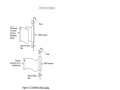
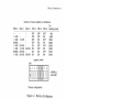
BEFORE YOU BEGIN...
This section presents information you'll need before you install
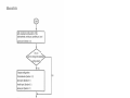
the SixPakPlus. Flgure 1-1 shows an overview of the steps you'll
take as you follow the instructions in Pa¡1 l, ,'Basic lnstallation,,.
Check package contents and system
requirements (Section 1 ).
Verify the factory configuration of the board
(Sections 2.1 and2.2).
Prepare your PC for installation (Section 2.3).
lnstall SixPakPlus in your PC (Section 2.4).
Test your installation (Section 2.S).
Figure 1-1. lnstallation Overview.
1-1
Basic lnstallation
1.1 Checking the Contents
Before you get started, check that your SixPakPlus package
includes the following:
¡
SixPakPlus circuit board.
SixPakPlus parallel intedace cable and bracket.
SuperPak diskette (version 5.1 or later).
SixPakPlus User's Manual (AST part number
000490-001 ).
SuperPak User's Manual (AST part number 000300-001).
Game port ribbon cable and bracket (if the game poñ
optlon is included on your SixPakPlus board).
1.2 Compatibility and System Requirements
To install SixPakPlus, you need an IBM PC, PC XT or fully
IBM P0-compatible computer wilh at least one unused full-length
expansion slot.
All references to operating system commands in this manual
assume operation under Disk Operating System (DOS) version
2.0 or later. SixPakPlus hardware is completely IBM-compatible
and willfunctlon properly under other IBM-approved operating
system software. Of course, conliguring the l/O porls under
another operating system requires the use of commands specific
to that operating system. See your operating system manual for
the appropriate command syntax.
1-2
Belore You Begln.,.
1.3 What You Need
to Know Before You Start
This section tells you what info¡'mation you need before you begin
installing SixPakPlus. You may have to make some modifications
to the SixPakPlus board configuration depending on how your
system is currently configured. A checklist appears at the end of
this section. Fill out the checklist as y6¡ answer each question.
A. How much memory is on the system board?
The system board on the PC, PC XT and most
compatibles can have a maximum of 256 KB. lf your
system board has less thalr 256 KB, you will need the
AST Research Memory Upgrade kit to increase the
memory on your SlxPakPlus board.
lf you have the older 64 KB PC system board, you will
have to expand the SixPakPlus' memory to the full
576 KB. See Appendix D for more information.
B. Do you have another memory board in your PC?
SixPakPlus willwork with other memory boards in your
PC as long as they do not conflict and their total
configured memory does not exceed the 640 KB
maximum. See Section 4 for more details.
C. How do you plan to use the serial port?
SlxPakPlus contains a serial port that allows your PC to
communicate with serial devices such as modems, mice
or serial printers (most printers are parallel). DOS
assigns each serial port in the PC a name; lhe first serial
port is called COM1, and the second (if present) is called
coM2.
lf your PC does not already have a serial port,
SixPakPlus' serial porl should be assigned to COM1.
Because this is the default setting lthe setting as
configured at the factory), you do not have to do
anything specialto make this assignrnent. lf your PC
already has a serial port (as is the case with the PC XT),
1-3
Basic lnstallation
you may want to assign the SixPakPlus' serial pon to
COM2 or disable it completely. See Section S for more
information.
D. How do you plan to use t/re parallel port?
SixPakPlus contains a parallel port that allows your PC to
communicate with parallel printers and other devices.
DOS assigns each parallel port in the PC a name. The
first parallel port is called LPT1, the second is LPT2 and
the third is LPT3.
lf your PC does not already have a parallel port, you
should assign the SixPakPlus' parallel port to LPT1.
Because this is the default settirrg (the setting as
configured at the factory), you do not have to do
anything special to make this assignment. lf you already
have a parallel port in your PC, you should configure the
SixPakPlus' parallel port as LPT2 (for the second port),
LPT3 (for the third port), or disable it. See Section 6 for
more information.
E. Do you want to use the ClocklCalendar?
The Clock/Calendar is a battery-run device that updates
the date and time while the PC is off, so you don't have to
"set it each time you boot the system. By default, the
Clock/Calendar is enabled and ready to use with the
ASTCLOCK software on the SuperPak diskette. lf you
already have a Clock/Calendar in your PC, you may
disable the Clock/Calendar on the SixPakPlus. See
Section 3 for more information.
F. Do you want to use the game port?
The game port is an optional accessory that lets you
connect IBM-compatible joysticks to your PC. Game
ports are available from your dealer. For more
information, see Section 7.
1-4
Belore You Begin...
1.3.1 Configuration Checklist
A. How much memory is already on the system board?
B.
Do you have another memory board in your PC?
nYesEruo
lf yes, how much memory is on the board?
C.
Use the serial port as (COM1, COM2 or disabled):
D.
Use the parallel porl as (LPT1, LPT2; LPT3, or disabled):
E.
Do you want to use the Clock/Calendar?
F.
Do you want to use the game port?
!
YesENo
!Yesnruo
1-5
tsasic lnstallalion
NOTES
1-6
CONFIGURAT¡ON AND INSTALLATION 2
Thls sectlon tells you how to conflgure your SlxPakPlus and lnstall
It ln your PC, Flgure 2-l summarlzes the SlxPakPlus installatlon
procedure.
2.1
Basic lnslallation
Verily standard conliguration of the
clock/calendar, serial port, parallel port, and
-wanl to change the standard
Change conflguration:
Clock/calendar (Section 3. 1)
Serial port (Section 5.1)
Parallel port (Section 6.1)
Game port (Section z.l)
Conligure the SixPakPlus board for starting
address, memory slze, and parity checklng
Get your IBM PC reâdy to lnstall the
SixPakPlus (Section 2.
lnstall the SlxPakPlus into your PC
(Section 2.4).
Test the new lnstallatlon (Section 2.S).
Flgure 2-1. SixPakPlus lnstallatlon Overview.
2-2
Conliguration and lnstallation
Section 2.6 provides a quick reference for the switch settings on
the SixPakPlus and the system board for the most common
configuration.
2.1 Factory Configurat¡on
The SixPakPlus is shipped from the factory in this configuration:
o
SixPakPlus has 64 KB installed. lf you purchased a
SixPakPlus with 384 KB installed, you may have to
change the switch settings. See Section 2.2.3.
r
Clock/calendar enabled (Section 3 tells you how to
change the clock/calendar configuration).
¡
Serial port configured as COMl, using interrupt line lRQ4
(Section 5 tells you how to change the serial pofi
configuration or disable it if you already lrave a serial porl
installed.)
.
All serial port input lines driven by the connected device
(Section 5 tells you how to change the serial porl
configuration or disable it if you already have a serial porl
installed.)
o
Parallel pofi configured as LPT1 (Section 6 tells you how
to change the parallel port configuration).
¡
Game port enabled, if the optional game port lOs are
installed (Section 7 tells you how to change the game
port configuration).
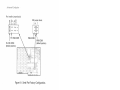
To verify standard f actory conf iguration, check that your
SixPakPlus board is configured as shown in Figure 2-2.
2-3
Basic lnstallation
RS-232C jumper block
Factory conf igurat¡on:
CM1: COM1 (enabled)'
Factory conf iguration:
1 Forced true (disabled)
2 Normal (enabled)'
1 Forced true (disabled)
2 Normal (enabled)'
1 Forced true (disabled)
2 Normal (enabled)'
DsR I
CM2: COM2 (disabled)
LPl: LPT1 (enabled)'
LP2: LPT2 (disabled)
GME: Game port (enabled)-
DcD
CLK: Clock/calendar (enabled)'
crs
{
{
. Jumper installed
'Jumper installed
Switch SWl
Standard
Factory conf iguration:
Pin 3: lRQ3 - COM2 (disabled)
Pin 4: lRQ4 - COM1 (enabled).
Pin 7: |RQT - LPTI (enabled)'
'
Jumper installed
settings:
Starting
memofy
-!SixPakPlus
address:
installed:
64 KB
256 KB
SWl-1: OFF
RAM
SWl-2: ON
SW1-4: OFF
SWI-S: OFF
SW1-3: ON
SWl-6: ON
Figure 2-2. SixPakPlus Board Layout.
2-4
Parity
Enabled:
SWl-8: ON
Conf iguration and lnstallation
2.2 SixPakPlus Configuration
Switch SW1, the memory configuration switch (Figure 2-3) on the
SixPakPlus, controls three different memory functions:
¡
The starting address of the SixPakPlus (Section 2.2.11.
¡
The amount of memory installed on the SixPakPlus
(Section 2.2.2).
r
Parity checking enabled or disabled (Section 2.2.31.
Section 4 of this manual tells you how to configure your board if
you are installing multiple memory expansion boards in your PC,
how to install additional memory onto yor.rr SixPakPlus, and how
to troubleshoot memory problems.
2.2.1 Quick Conliguration lor Switch SWI
This section outlines the switch settings for SW1 that are
appropriate for most users. You can use these settings if
r
:
The factory configuration described in Section 2.1 is
satisfactory.
¡
Your PC currenlly has 256 kilobytes (KB) of memory.
lf these conditions apply, skip Sections 2.2.2lhrough 2.2.4 and
set SW1 as shown in Figure 2-3. lf these conditions do not apply,
follow the instructions in Sections 2.2.2 through 2.2.4.
2-5
Basic lnstallation
Standard settings for sw¡tch SWl
sw1-1 swl-2 sw1-3 sw1-4 sw1-5 swl-6 sW1-7
OFF ON ON OFF OFF ON
ON
SW1-8
ON
Figure 2-3. Standard Settings lor Switch SW1.
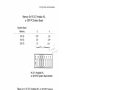
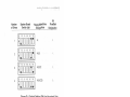
2.2.2 SixPakPlus Starting Memory Address
The SixPakPlus card must be configured to indicate how much
memory is inslalled below it -- that is, what its starling address
should be. Positions 1 through 3 of SW'l set the SixPakPlus
starling address as shown in Figure 2-4.
SixPakPlus Starting Memory Address
Starting
address SWl-l SW1-2 SWl-3
OFF
OFF
l:30000) OFF
(:a0000) OFF
(:50000) ON
384 KB (:60000) ON
448 KB (:70000) ON
512 KB (:80000) ON
. Factoryconfigura#
64 KB
128 KB
192 KB
-256 KB
320 KB
(:10000)
(:20000)
OFF
OFF
ON
ON
OFF
OFF
ON
ON
OFF
ON
OFF
ON
OFF
ON
OFF
ON
Maximum RAM
on SixPakPlus
s76
512
448
384
320
256
KB
KB
KB
KB
KB
KB
192 KB
128 KB
swl
SixPakPlus
Switch
Figure 2-4. Starting Address Settings.
2-6
1
Configuration and lnstallalion
Set the SixPakPlus staning address to the setting in Figure 2-4
that corresponds to the amount of memory installed on the
system boarcl. For example, if your PC has 192 KB installed on its
system board, set the SixPakPlus starting address to 192 KB
(SW1-1 OFF, SW1-2 ON, and SW1-3 OFF).
NOTE
The SixPakPlus staning address should be above
256 KB only if another memory expansion card is
installed "below" the SixPakPlus board. Section 4
tells you how to install other memory boards into
your PC along with the SixPakPlus.
2.2.3 Amount ol SixPakPlus Memory
You must set SW1 positions 4 through 6 to tell the SixPakPlus
how much memory is installed on it (see Figure 2-5).
Number of banks installed on SixPakPlus
Bank
64
64
256
64
64
256
64
0
KB
KB
KB
KB
KB
KB
KB
Bank
1
Bank
_KB _
64
256
64
256
256
KB
KB
KB
KB
2
sw1-4 sw1-5 swl-6 lïtÊl*r,r"
3FF 3FF
OFF
OFF
ON
256 KB ON
ON
256 KB ON
SW1
ON
ON
OFF
OFF
ON
ON
3['
OFF
ON
OFF
ON
OFF
ON
.
,o"
.î [3.
128 KB
256 KB
320
384
512
576
KB
KB
KB
KB
Factory conf¡guration
SixPakPlus
switch SW1
Figure 2-5. SixPakPlus Memory Size Settings.
When the staning address is 320 KB or higher, the SixPakPlus
automatically limits the amount of usable memory on the card.
This prevents conflicts with areas of rrrernory reserved for the
2-7
Basic lnslallation
monochrome or color display cards. This occurs even if SWl
positions 4 through 6 are configured for more memory than the
maximum indicated in Figure 2-5.
NOTE
Position 7 on SixPakPlus switch SWl is not used,
and it can be ON or OFF.
2.2.4 Parily Check Enable
SW1 position I on your SixPakPlus (see Figure 2-6) enables or
disables full parity error checking. To erìsure the highest possible
data integrity, you should always enable the parity check function
by leaving SW1-B ON. However, if you want to disable parity
checking, set position I OFF.
swl
SW1-8 ON = Parity enabled
SWl-8 OFF = Parity disabled
Figure 2-6. Parity Check Enable Setting.
2-8
Conf iguration and lnstallation
2.3 Gett¡ng Your PC Ready
Before you can install the SixPakPlus, you must turn off your PC,
renìove its cover, and verify the switch settings on the system
board.
CAUTION
Be sure that the power switch is off and the
power cord is removed from the system unit.
Turn off any other equipment connected to the
computer. lnstalling any component while the
power is on can permanently damage your
computer and its components.
You will need a flathead screwdriver or nut driver to perform the
following procedure.
STEP 1
Remove cover: Bemove the cover retaining screws on the rear
panel of the PC and pull the PC cover off (see Figure 2-7).
2-9
Basic lnstallation
Figure 2-7. Removing the PC Cover.
STEP 2
Set the PC DIP switch:
PC: See Section 2.3.1.
PC XT, Portable PC, and 3270 PC: See Section 2.3.2.
lf you are installing SuperDrive at thls time: See Section
2.3.3.
2-10
Configuration and lnstallation
You can also refer to the IBM Guide to Operations manual for
your PC model.
NOTE
lf you have an IBM Expansion Unit, you must set
the Extender Card DIP switch to reflect the total
amount of memory installed (system memory
plus SixPakPlus memory).
2.3.1 PC System Board Switch Settings
You must tell the PC how much total memory (including any
expansion memory, such as the SixPakPlus) is installed in the
computer. Do this by setting the PC system board switch SW2 as
described below. Figure 2-8 shows the position of SW2 on the pC
system board.
2-11
Basic lnstallation
sw2
Figure 2-8. PC System Board Layout.
the amounl of memory on the system board and the amount
of memory on the SixPakPlus. Set PC system board switch SW2
to the total as shown in Figure 2-9.
AcJci
2-12
Conliguration and lnstallation
Total Memory lnstalled
Total
Memory SW2-1 SW2-2 SW2-3 SW2-4
64 KB
'128 KB
192 KB
256 KB
320 KB
384 KB
448 KB
512 KB
576 KB
640 KB
ON
ON
ON
ON
ON
ON
ON
ON
ON
ON
ON
OFF
ON
OFF
ON
OFF
ON
OFF
ON
OFF
ON
ON
OFF
OFF
ON
ON
OFF
OFF
ON
ON
ON
ON
ON
ON
OFF
OFF
OFF
OFF
ON
ON
SW2-s
ON
ON
ON
ON
ON
ON
ON
ON
OFF
OFF
PC System Board
Switch
2
Figure 2-9. PC System Board Switch Settings.
2-13
Basic lnstallation
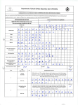
2.3.2PC XT, Portable PC, and 3270PC System Board Switch
Settings
Switch SWl (positions SW1-3 and SW1-4) in the PC XT, Porlable
PC, or 3270 PC tells the computer only how much memory is
installed on the systen'ì board itself. Expansion memory on the
SixPakPlus willautomatically be recognized. The system board
used in these computers does not have to be fully populated to
use expansion memory. Figure 2-10 shows the position of SW1
on the PC XT. Verify that the system board switch is properly set
as shown in Figure 2-11.
Iilil
Figure 2-10. PC XT System Board Layout.
2-14
Conliguration and lnstallation
Memory On PC-XT, Portable PC,
or 3270 PG System Board
System Board
Memory
128 KB
192 KB
3
OFF
ON
4
ON
OFF
256 KB
PC XT, Portable PC,
o¡ 327O PC System Board Swltch
Flgure 2-11. PC XT, Podable PC, or 3270 PC System
Board Switch Settlngs.
2-15
Basic lnslallation
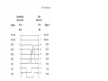
2.3.3 Setting SWI for The Number of Floppy Drives
Your SixPakPlus cornes standard with the SuperDrive disk drive
simulation program. lf you will be using SuperDrive, you must set
the system board switch SWl (posilions SW1-'1, SW1-7, and
SW1-8) at this tims for the number of floppy drives in your PC, as
shown in Figure 2-12.'fhe position of switch SW1 on the PC
system board is shown in Figure 2-8. The position of switch SW1
on the PC XT system board is shown in Figure 2-10. SuperDrives
appear to the system as floppy drives, so include them in your
count; if your system has a fixed (hard) disk, do not include it in
the count.
For further information on the SuperDrive program (or any of the
other SuperPak programs), see your SuperPak User's Manual.
2-16
Conliguration ancl lnstallalion
Configuration and lnstallation
Number
of
IBM
drives System Board Floppy/SuperDrive Fixed Disk
Designations Designation
and SuperDrives Switch #1
floppy
ffi
ffi
ffi
ffi
A:
C:
A:B:
C:
A:B:C:
D:
A:B:C:D:
E
Figure 2-12. System Board Switch Setlings for Floppy
Drives and SuperDrives.
2-17
Basic lnslallation
2.4 lnstalling SixPakPlus into Your PC
You can installthe SixPakPlus card in any unused full-length
expansion slot orr the systenr board.
CAUTION
Be sure that the power is off and that the power
cord is removed from the PC before installing or
removing any equipment.
STEP 1
This step is required only if you plan to use the game or parallel
printer ports mounted on tlre supplied brackets. lf rrot, go cJirectly
to STEP
2.
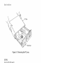
lnstall the ribbon cable(s): Find the ribbon cable(s) for the
parallel port and/or the game port (shown in Figure 2-13). The
parallel pon ribbon cable is about 1-114 inches wide, with a
rectangular connector at otle end and a DB25S connector at the
other end. The game port ribbon cable is about 3/4 inches wicJe,
with a rectangular connector at one end and a DBI53 connector
at the other end.
Each ribbon cable comes with a brackel. Use the hardware
supplied with each D-shell connector to rnount the connector on
its bracket. Parallel port:Plug the rectangular connector onto
connector J2. Game port: Plug the rectangular connector onto
connector J3. (Figure 2-2 shows the locations of conneclors J2
and J3.)
2-18
Configuration and lnstallation
Rectangular
Connector
(to J2 on
SixPakPlus
board)
Rectangular
Connector (to J3 on
OB155 Connector
SixPakPlus board)
Figure 2-13. SixPakPlus Ribbon Cables.
Plug the connector onto the board so that pin 1 on the
rectangular connector (indicated by a triangle and the stripe on
the ribbon cable) is closest to pin 1 on the J2 or J3 connector
(indicated by the "1" silkscreened in white on the boarcl), as
shown in Figure 2-14.
2-19
Basic lnstallation
Ribbon Cable
Silkscreened "1
"
Figure 2-14. lnstalling the Ribbon Cable onto
SixPakPlus.
STEP 2
Se/ect an open expansion s/ot; The SixPakPlus board requires
one full-length slot. You will need an additional slot (not
necessarily full-size) if you use the parallel port bracket or the
game pon bracket.
STEP 3
Bemove brackets: Locate the metal bracket that covers the
cutout in the back panel of the PC chassis for the slot that you
2-20
Configuration and lnstallat¡on
have selected. Remove and save the l¡racket retaining screw
using a smallflathead screwdriver. Remove the bracket.
STEP 4
lnstallthe SixPakPlus board: Lower the card until its edge
connector is resting on the expansiorr slot receptacle. Using an
evenly distributed pressure, press the SixPakPlus straight down
until it seats in the expansion slot (Figure 2-15).
SixPakPlus
Board
Card Guide
Figure 2-15. lnstalling Your SixPakPlus Board.
2-21
Basic lnstallation
STEP 5
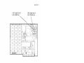
lnstall parallel port andlor game port: lnstall the bracket(s) with
the D-shell connector(s) into the cutout(s) you have chosen.
Figure 2-16 illustrates an example installation, including one
ribbon cable.
NOTE
To avoid wear on the ribbon cable when you
remove and replace the PC cover, route the
parallel port and garne port cables under other
boards in the PC whenever possible.
Secure Brackets With Scrows
Parallel Port Connector
T
1|ilililll
llll
NOTE: Thls ls an example only: you can lnstall the SlxPakPlus and lts parallel
port lnto any open slots ln the PC. (SlxPakPlus boârd requlres tull-slze slot)
Figure 2-16. Example Installation (One Ribbon Cable).
2-22
Corrf
iguration and lnstallation
STEP 6
Reinstall the bracket retaining screwls)j Secure the bracket(s) to
the rear of the PC chassis.
STEP 7
Replace PC cover: You can replace the system unit cover now,
or you can wait until you've checked the new installation
(Section 2.5).
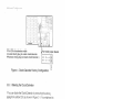
STEP 8
lnstallcables: Replace the power cord to the system unit and be
sure that the keyboard and the monitor connectors are plugged in
(Figure 2-17).
Keyboard
Cabte --
Figure 2-17. lnstalling Cables.
2.5 Testing the New lnstallation
Test your new installation with the following procedure.
STEP
1
With the power off, insert an IBM Disk Operating System (DOS)
diskette in drive A, and turn on the power. lf the installation was
done correctly, the system will boot normally. Because there is
now more memory installed in your PC, the PC will take longer to
boot up than before.
2-23
Basic lnstallation
STEP 2
Run the IBM diagnostic routines to check out the features you
have just installed. See your IBM Guide to Operations manual for
instructions. The diagnostic routines do not test the
clockicalendar feature.
STEP 3
Use the clock/calendar software (inclucled on your SuperPak
diskette) to set the correct time and date on your SixPakPlus.
Section 3 tells you how to set your SixPakPlus clock/calendar.
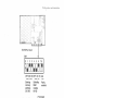
2.6 Quick Reference Configuration
Figure 2-18 summarizes lhe switch settings for the most common
configuration. The settings in this section are appropriate if:
r
The factory configuration described in Section 2.1 is
installed.
¡
The PC has 256 KB of memory, and the SixPakPlus has
64 KB.
The SixPakPh.¡s is installed in a PC (not a PC XT) which
has 256 KB on the system board.
The PC has two floppy drives and one SLrperDrive (the
presence or lrumber of hard drives is irrelevant).
2-24
Configuration and lnstallation
OFF ON ON OFF OFF ON ON
\--
.#
Starting SixPakPlus
-\,,memory RAM
address: installed:
256 KB
64 KB
Parity
enabled
lilll
PC System Board
Switch SWl
OFF
Switch SW2
ON
3 Floppy
Drives
OFF
ON OFFON ON OFF
256 KB on System Board
Figure 2-18. Quick Reference Configuration.
2-25
Basic lnstallation
NOTES
2-26
3. Clock/Calendar
4. MemoryConfiguration
5.
Serial Port
6.
Parallel Poft
7, Game Pofi
NOTES
CLOCK/CALENDAR
3
The SixPakPlus Clock/Calendar can answer the TIME and DATE
prompts that the Disk Operating System (DOS) issues each time
you boot the system. The PC is not aware of the existence of any
expansion card clÖck unless you use the clock software supplied
on your SuperPak dlskette.
NOTE
You must use a version 5.1 (or later) SuperPak
diskette with your SixPakPlus.
The standard SixPakPlus Clock/Calendar features include:
o
24-hour clock, maintained in an advanced
microprocessor chip on the SixPakPlus board.
o
Battery backup power supply (with a battery life of
approximately one year).
.
Replaceable lithium battery.
¡
Full PC-DOS compatibility.
o
Automatic accounting for leap year.
3.1 Configur¡ng the Clock/Calendar
SixPakPlus is shipped from the factory with the clock/calendar
enabled. To confirm the default configuration, check that a
shorting plug is installed at position CLK of the Port Enable
Jumper Block, as slrown in Figure 3-1.
3-1
Aclvanced Configuration
Pin CLK-clock/calendar enable
(lnstall shorting plug to enable clock/calendar.
Remove short¡ng plug to disable clock/calendar.)
Port enable jumper block
Figure 3-1. Clock/Calendar Factory Conliguration.
3.1.1 Disabling the Clock/Calendar
You can disable the Clock/Calendar by removing the shorting
plug from position CLK as shown in Figure 3-1. You might want to
disable the Clock/Calendar to avoid a conflict between the l/O
addresses used by the SixPakPlus clock and other devices
installed in your PC. The SixPakPlus Clock/Calendar uses l/O
addresses 02C0h through O2C7h.
Section 3.5 provides furlher technical information on the
SixPakPlus Clock/Calendar.
3.2 Prepar¡ng Your PC Boot Disk
Once you've installed your SixPakPlus card, you can prepare
your PC boot disk to automatically initialize the time ancj clate
each time that you boot the system. This subsection tells you how
to prepare your DOS disk to automatically invoke the
Clock/Calendar.
3-2
Clock/Calendar
STEP 1
lf you have not already done so, copy rhe ASTCLOCK.COM
program from a SuperPak diskette (version 5.1 or later) to your
PC boot disk.
lf you are unsure how to COPY a file, consult your DOS Manuat.
STEP 2
lf your working DOS diskette already has an AUTOEXEC.BAT file,
you tnust alter that file to include the ASTCLOCK command. To
see the current contents of your AUTOEXEC file, enter this
command (with AUTOEXEC.BAT in the default drive):
TYPE AUTOEXEC.BAT < Enter >
Your screen will display the contents of your AUTOEXEC file. Now
you must create a new AUTOEXEC file in which the command
ASTCLOCK precedes these other command(s). Enter thls
command sequence:
COPY CON: AUTOEXEC.BAT< Enter>
ASTCLOCK< Enter>
.
(other commands)
ifunct¡on
key F6> <Enter> or <Ctrl-Z> <Enter>
lf your working DOS disk has no AUTOEXEC fite, use the
sequence above to create one (the only command in the file will
be ASTCLOCK).
For more information about AUTOEXEC files or the DOS COpy
command, see your DOS Manual.
3-3
Advanced Conliguration
NOTE
lf you want ASTCLOCK to display the date in
European format (dd/mm/yy) when you boot the
system, substitute the command ASTCLOCK/E
for ASTCLOCK in your AUTOEXEC file.
Specifying the E parameter in the AUTOEXEC file
only changes how ASTCLOCK shows the date
when you boot the system; it does not affect how
DOS or other software displays the date.
STEP 3
Reboot your PC (press the
sequence).
<Ctrl>-<Alt>-< Del> key
The ASTCLOCK command will dlsplay the time and date on the
screen. lf necessary, use the ASTCLOCK /R parameter to set the
TIME and DATE on the SixPakPlus as detailed in Section 3.3.
3.3 Setting the Time and Date
This section tells you how to set the time and date in the
SixPakPlus clock chip.
NOTE
You must use a version 5.1 (or later) SuperPak
diskette to set the SixPakPlus clock chip.
Once you have copied ASTCLOCK to your PC boot disk, you can
update the Clock/Calendar on the SixPakPlus internal
microprocessor chip. DOS TIME and DATE commands only
update the system's time and date parameters in memory; they
don't permanently update the values stored in the SixPakPlus
clock chip until you execute this procedure:
STEP 1
Boot the system with a disk that contains the ASTCLOCK.COM
program.
3-4
Clock/Calendar
STEP 2
Enter this command:
ASTCLOCK
/RcEnter>
Your PC will then display a message like this (the actual date and
time will be different):
ASTclock
Versionx.xx
(c) Copyright AST Research, lnc.,
1982,1984,1985.
resident clock/calendar
DATE & TIME processors loaded.
Current date is 05121187
Current time is 0B:07:56.65
NOTE
lf you want ASTCLOCK to display the date in
European format 1Od/mm/VV) when you enter this
command, type ASTCLOCK/R/E instead of
ASTCLOCK/R. Specifying the /E parameter only
changes how ASTCLOCK shows the date when
you enter this command; it does not affect how
DOS or other software displays the date.
STEP 3
Enter this DOS command:
DATE < Enter>
Your PC will display the current date (the actual date displayed
may be different):
Current date is Thurs 5-21-1987
Enter rrew date:
Enter the new month, day, and year as follows:
3-5
Advanced Conliguration
mm-dd-yy< Enter>
where rnm is the one or two-digit month designation, dd
is the day, and yy is the year.
lf you do not want to change the date, press < Enter
>
only.
STEP 4
Enter this DOS command:
TIME < Enter >
Your PC will then display the current time (the actual time
displayed may be different):
Current tirre is B:14'.15 82
Enter new tirne:
Enter the new hour, minute, and second as follows:
hh:mm:ss < Enter >
where hh is the hour, mm is the minute, and ss is the
second. Be sure to use 24-hour format for the hour (lhat
is, 1:00 PM : 13:00,2:00 PM : 14:00, and soon).
Do not enter hundredths of a second, lf you do not want to
change the time, press < Enter > only.
Hint: For maximum accuracy, type in a time that is
10
to
1S
seconds ahead of the actual time, then observe a cligital
watch, and press < Enter > when the seconds reading on
the watch catches up to the value that you typed in.
STEP 5
Fìeboot your computer by pressirrg the < Ctrl > - < Alt > - < Del >
key sequence.
3-6
Clock/Calendar
NOTE
Selecting the ASTCLOCK /B parameter selects
the resident option, which allows you to update
the date and time in both PC memory and the
SixPakPlus clock chip (you cannot update the
clock chip unless a ceftain poftion of the
ASTCLOCK.COM program is resident).
lf you use the ASTCLOCK command without the /R pararneter, it
simply initializes the PC's date and time by reading that
information from the SixPakPlus clock chip, and then "goes
away"; no portion of ASTCLOCK remains resident, so you cannot
update the date and time information in the clock chip.
3.4 The Glock/Calendar Battery
The lithium Clock/Calendar battery should last for about a year,
and is easily replaceable. You can purchase replacement
batteries from your AST product dealer (pan 108-8F2325).
Compatible substitution batteries can also be purchased from
local camera or depaftment stores. Table 3-1 lists compatible
lithium batteries.
3-7
Advanced Conliguration
Table 3-1. Compatible Clock/Calendar Batteries.
Manulacturer
AST
Duracell
General Electric
Panasonic
Ray-O-Vac
Sanyo
Vafia
Radio Shack
Pafl Number
1
08-8R2325
DL2032
8R2325
8R2325
8R2325
cR2032
cR2032
cR2320H*
*Compared to the other batteries listed in this table, the Radio Shack
battery is .5 mm thinner and ratecl at 50 mAh less than the other
batteries listed. lts life expeclancy is approxinrately 9 months
(compared to a yeaf for the other batteries).
Because the battery is used or'ìly when your PC is not operating,
the actual life of your battery will l¡e determined by how much the
PC is used. The clock chip on your SixPakPlus is powered by the
PC system when your PC is on. The battery is used as backup
power only while your PC is off.
To replace tlte battery, slightly lift the retaining clip with your
finger (or a small screwdriver) and use your thumb or another
small screwdriver to slide the silver battery sideways out of the
battery socket (Figure 3-2). Do not rernove tlre battery socket
from the board.
3-8
Clock/Calendar
Lift retaining
clip slightly
+
Push battery
out sideways
Push through slots on
battery socket for
easiest removal
Figure 3-2. Removing the SixPakPlus Clock/Calendar
Battery.
Take care not to damage or bend the retaining clip by lifting it too
far. The clip completes an electrical circuit and must make solid
contact with the positive (+ ) side of the battery. Whenever the
battery is removed, it ls a good idea to check the clip in the
bottom of the battery holder. Be sure tl'ìat it is sticking up high
enough to make good contact with the bottom surface of the
battery. When installing a new battery, make sure it is clean and
dry.
NOTE
lf you replace the battery, be sure to use the
procedure described in Section 3.3 to restore the
proper time and date.
3.5 Technical lnformat¡on
The SixPakPlus Clock/Calendar chip is the RICOH RPsC15, and
uses l/O locations 02C0h through o2C7l't. For more information,
consult the programming information in the R/COH
RP5C01IRPSC15 Application Manual. AST Research calrnot
provide any information other than what is presented here.
3_9
Advanced Conf iguration
NOTES
3-10
MEMORY CONFIGURATION
4
This section tells you how to:
r
lnstall other memory expansiorr boards in your PC along
with tlìe SixPakPlus (Section 4.1).
o
lnstall additional mernory on your SixPakPlus board
(Sectiotr +.2).
r
Troubleslroot memory problems (Sectiorr 4.3).
Section 2 of this manual tells you how to configure your
SixPakPlus board (for stañing address, memory size, and parity
error checking enable/disable) before you install it into your PC.
4.1 lnstalling Multiple Memory Boards into Your
PC
The advanced design of the AST Research SixPakPlus makes it
compatible with most otlrer exparrsion boards available for the
IBM PC. However, when more than one memory expansion board
is installed, you must configure the boards to prevent conflicts
between them.
When you install multiple mernory boards, you must first
determine where each board is to reside in the PC's memory
area. You can usually install your SixPakPlus eitlrer "above" or
"below" the address space occupied by another board:
¡
Section 4.1 .1 tells you how to install anotlrer mernory
board "below" the SixPakPlus.
r
Section 4.1 .2 tells you lrow to install another memory
board "above" tlre SixPakPlr¡s.
4-1
Advanced Conf iguration
4.1.1 lnstalling a Board "Below" the SixPakPlus
To address another memory board "below" the SixPakPlus, follow
this procedure:
STEP
1
Contigure other board to reside immediately "above" the PC
system board memory: Follow the configuration instructions
supplied with the other board.
STEP 2
Disable any unused memory sockets on the other board; lf there
are any unused rows of memory sockets on the other board,
disable them so they won't conflict with the SixPakPlus. Refer to
the other board's manualfor information on how to disable
unused sockets. lf you cannot disable unused memory sockets,
you should address the other board "above" the SixPakPlus (as
described in Section 4.1.2l'.|f the other board has switch settings
for the amount of memory on it, then it will probably automatlcally
disable any unused memory sockets.
STEP 3
Set the SixPakPlus starting address and memory ske: Add the
amount of memory on the other board to the amount of memory
on the PC's system board, and set the SixPakPlus startirrg
address at this value as shown in Figure 2-2 (Section 2 of this
manual). Set the SixPakPlus memory size as shown in Figure 2-3.
STEP 4
PC: Sef the PC system board swifches for the total amount of
memory in your PC; The total amount of memory includes the
system board, the SixPakPlus, and tlre other memory expansion
board.
PC XT, Podable, and 3270 PC: Check that the PC system board
switches are set for the memory installed on the system board
only (do not include the memory on the SixPakPlus or any other
expansion memory board). Unless you have changed the amount
of system board memory, these switch settirrgs should not
change.
4-2
Memory Configuration
NOTE
lf you have an IBM Expanslon Unlt, you must set
the Extender Card switch to reflect the total
amount of memory installed (system memory
plus expansion board memory).
4.1.2lnstalling a Board "Above" the SixPakPlus
To address another memory board "above" the SixPakPlus, follow
these steps:
STEP 1
Set the SxPakP/us starting address and memory size: The
SixPakPlus starting address corresponds to the amount of
nìemory on the PC system board. Set the memory size for the
amount of memory on the SixPakPlus itself (see Figures 2-2 and
2-3).
STEP 2
Set the other board's startrng address and memory s2e: Add the
total memory installed on your PC system board to the amount of
SlxPakPlus memory. Follow the lnstructions supplied with the
other memory board to set its starting address for this total. lf
necessary, also configure the other board for the amount of
memory lnstalled on it.
STEP 3
PC: Sef the PC systern board switches for the total amount of
memory in your PC: The total amount of memory includes the
system board, the SlxPakPlus, and the other memory expanslon
board.
PC XT, Podable PC, and 3270 PC: Check that the PC system
board switches are set f or the memory installed on the sysfem
board only (do not include the memory on the SixPakPlus or any
other expanslon memory board). Unless you have changed the
amount of system memory, these settlngs should not change.
¿t-3
Advanced Configuration
NOTE
lf you have an IBM Expansion Unlt, you must set
the Extender Card swltch to reflect the total
amount of memory lnstalled (system memory
plus expansion board memory).
4.2 ln_stalling Additional Memory on the
SixPakPlus
It is easy to add memory to your SixPakPlus any time; you can
upgrade the SixPakPlus to a maximum 576 kllobytes (KB) of
random access memory (RAM). You may add 64- or 2S6-KB
RAM chip sets, or a combinatlon of both, to conflgure the
SixPakPlus board to the amount of memory you need.
Figure 4-1 shows which RAM chlp sets and swltch settlngs are
required to conflgure your SixPakPlus board to the amount of
memory you want.
4-4
Memory Configuration
Number of banks installed on SixPakPlus
Bank
64
64
256
64
64
256
64
0
KB
KB
KB
KB
KB
KB
KB
Bank
1
KB
256 KB
64 KB
256 KB
256 KB
64
Total
2 SW1-4 SWI-S SWl-6 SixPakptus
OFF
OFF OFF
O KB
OFF
OFF ON
64 KB'
OFF
ON OFF 128 KB
OFF
ON ON 256 KB
ON
OFF OFF 320 KB
256 KB ON
OFF ON 384 KB
ON
ON OFF 512 KB
256 KB ON
ON ON 576 KB
Bank
ffi
RAM
sw1
'
SixPakPlus
switch SW1
Factory conf¡guration
Figure 4-1. Memory Configurat¡on.
RAM upgrade kits are available from AST in either 6a KB (Model
No. MP-0009) or 256 KB (Modet No. Mp-1S0) sers. lf you want ro
upgrade the SixPakPlus with your own chips, see the
specifications in Section 4.2.1Íor 64 KB RAM chips or Section
4.2.2Íor 256 KB.
4-5
Advanced Conf iguration
NOTE
You must use chips that meet the specifications
listed in Sections 4.2.1 and 4.2.2. lÍ you install
chips that do not meet these specifications, your
computer may malf unction.
lf you wish to use the AST memory upgrade kits, you may sklp to
Sectlon 4.2.3 tor installation instructions.
4.2.1 64-KB RAM Upgrade Chips
lf you want to upgrade the SixPakPlus yourself with 64 KB chips,
use dynamic random access memory (DRAM) chips wlth these
characteristics:
150 or 200 nanosecond (ns) access time
Pin 1 not used
+ 5 Volt only
The memory chips listed in Table 4-1 are compatible with the
SixPakPlus and the PC or PC XT system board.
rF6
Memory Configuration
Table 4-1. Compatible 64-KB Memory Chips.
Manulacturer
Part Number
AMD
Fujitsu
4M9064-1 5PC, AM9064-20PC
M88264-1 5P, M88264-20P
HM4864P-2
lM32600P-15
P2164A-15, P2164A-20
MT4264N-2, MT4264N-1 5,
MT4264N-3, MT4264N-20
M5K41 64ANP-1 5, M5K41 64ANP-20
MK4564N-1 5, MK4564N-20
MCM41 648P1 5, MCM6665AP1 5,
MCM6665BP1 5, MCM6665AP20,
MCM6665BP20
uPD41 64C-2, UPD41 64C-3
MSM3764-1 5RS, MSM3764-20RS
TMS41 64-1 5NL, TM341 64_20NL
TMM41 64P-3, TMM41 64P-4,
TMM41 64AP-1 5, TMM4't 6 4AP -20
Hitachi
lnmos
lntel
Micron Technology
Mitsubishi
Mostek
Motorola
NEC
oKt
Texas lnstruments
Toshiba
4.2.2 256 KB RAM Upgrade Chips
lf you want to upgrade the SixPakPlus yourself vuith 256 KB chips,
use dynamic random access mernory (DRAM) chips with these
characteristics:
100, 120 or 150 nanosecond (ns) access time
Pin 1 not used
+5 Volt only
The memory chips listed in Table 4-2 are compatible with the
SixPakPlus.
4-7
Advanced Conf iguration
Table 4-2. Compatible 256 KB Memory Chips.
Manufacturer
Pa¡t Number
AT&T
wcM41256FX-15
Fujitsu
Hitachi
Mitsubishi
Motorola
M881256-15
HM50256P-15
M5M4256P
MCM6256L
D41256C-15
TMS4256-15N1
TMM41256P-15
NEC
Texas lnstruments
Toshiba
4.2.3 lnstalling RAM Chips
Follow this procedure when you add memory to the SixPakPlus:
STEP 1
Shut off the power to the PC and remove the SixPakPlus board
from the PC.
STEP 2
lnstall each additional set of nine 64- or 256-KB memory chips in
the next empty bank on the board. For example (refer to
Figure 4-1) if your SixPakPlus has 64 KB on it now, it has memory
in Bank 0 only. lf you want add 320 KB to SixPakPlus to bring the
memory up to 384 KB, you will inslall one set of 64-KB chips in
Bank 1 and one set of 256 KB chips in Bank 2.
lnstall the new chips carefully, and take care not to bend the legs.
lnstall the new chips so that the notched ends face the same
direction as the other memory chips installed on the board (see
Figure 4-2).lf the memory chip is not notched, install it so that the
pin 1 indicator (a dot in one corner of the chip) faces toward the
lower left corner of the board.
4-8
Memory Configuration
NOTE
Each bank of nine chips must be populated
entirely. Do not intermix 64 KB and 256 KB chips
in the same bank.
STEP 3
Set SixPakPlus DIP switch SW1 for the new total amount of
memory on the board. Figure 4-1 shows you how to set SW1 for
the SixPakPlus memory size.
STEP 4
PC only: Set DIP swiÌch SW2 on the PC system board to the new
total amount of memory installed in the PC (see Figure 2-8). Thls
step is unnecessary for the PC XT, Portal¡le PC, or 3270 PC.
STEP 5
Reinstall the SixPakPlus into the PC and power it up. Now that
there is rnore memory in the PC, the powerup diagnostics will
take longer to run. lf all goes well, the system should operate
normally and show the correct new ìotal amount of memory when
you enter the DOS CHKDSK command.
You can also run the IBM diagnostic routines (see your IBM PC
Guide to Operations manual).
lf you get an error, recheck the installation of the new chips and
the switch settings on both the system board and the SixPakPlus.
lf everything appears to be correctly installed and configured, and
you still get an error, then proceed to Section 4.3 for help in
troubleshooting the problem.
4-9
Advanced Conliguralion
64-KB or
256-KB
äåTil;'hþ"-^" -.
/'o'"n
17
\r,n
r
rndrcator
Figure 4-2. SixPakPlus Memory Banks.
4.3 Troubleshooting Memory Problems
The most common indication of a mernory problem in the pC is a
PARITY CHECK 2 message on powerup. These examples
illustrate the format of error messages you might see.
lf you have a PC, an error message might look like this:
4020 201
4-10
Memory Conliguration
lf you have a PC XT, Portable PC, or 3270 PC, an error message
might look like any of these:
40000 20 201
40000 (S)
40000 (S) 201
????? (s) 2o1
Sometimes you can use the error code to isolate the problem to a
specific memory chip.
The first digit of the error message indicates in which 64-KB bank
the error is occurring. The message 4O2O or 40000 tells us that
the error is occurring in Bank 4 of the PC. Because the computer
numbers its memory banks beginning with Bank 0, Bank 4 is
actually the fifth bank in the system.
the
"20" in the first two examples tell you which chip in the bank
(that is, which bit in the B-bit data byte) is failing. Look at
Figure 4-1: the fourth chip from the top of each memory bank is
numbered "20".
An error code of "4020" or "40000 20" means that the fourth chip
(the chip numbered "20" in Figure 4-1) from the top of the fourlh
memory bank in the PC is failing. lf you have a PC with 256 KB
(Banks 0 through 3) inslalled on its system board, Bank 4 would
be the first bank on the SixPakPlus board, The "201" in the error
message indicates that there is a probiem in memory.
Once you determine which chip you believe is causing the
problem, replace it with a spare chip and see if the error is
corrected (you can tell that the error is corrected wherr you
reboot your PC and il does not display an error message). lf no
spare chip is available, try exchanging the suspect chip with
another one in the same bank which is not failing. lf the error then
moves to the new socket, you definitely have a bad chip. lf the
4-1
1
Advanced Conf iguration
error persists at the original socket, you may have a problem with
the board; contact your dealer for assistance.
lf you get an error message such as "40000 (S) 201", it tells you
that you have a memory problem in Bank 4 in your PC; the "(S)"
simply means that the failing chip is somewhere in the system unit
(that is, somewhere in your computer). The best way to isolate
the problem chip is to swap each chip in the failing bank with a
good chip and see if the error is corrected.
lf you get a"????? 201" error message, it tells you only that you
have a memory problem somewhere in your cotnputer. You can
try to isolate the problem bank by swapping each memory bank
with good memory chips, Once you have delermined which
memory bank is failing, you can replace each of the original chips
and reboot your computer each time you replace a chip. An error
message at boot-up then indicates a faulty chip.
lf the bit number of the error code does not match any of the
values shown in Figure 4-1, you might have more than one failing
memory chip. Thls could be due to a malfunctioning board,
incorrect switch settings, mulliple bad memory chips, or even
something as simple as a dirty gold edge connector.
lf the failing bank number is higher than the amount of memory
installed in the PC, recheck your system board switch settings.
lf you cannot correct the problem, contact your dealer for
assistance.
4-12
SERIAL PORT
5
Your SixPakPlus comes standard with one serial port for
asynchronous communications. You can use the serial porl to
connect your PC to a serial printer, modem, or other device which
uses an RS-232C interface. The SixPakPlus interface is a DTE
type (Data Terminal Equipment) with a male DB25P connector.
This section includes the following information:
¡
Section 5.1 tells you how to reconfigure the serial pott:
changing COMl to COM2, forcing RS-232C inputs true,
and disabling the SixPakPlus serial port.
¡
Section 5.2 discusses serial poft programming.
o
Section 5.3 gives serial pott l/O address assignments and
pinouts,
o
Section 5.4 discusses serial pon diagnostic testing.
5.1 Configur¡ng the SixPakPlus Serial Port
You can install up to two serial potts (called COM1 and COM2)
into your PC. The SixPakPlus serial pott has been factory
configured to respond as COMl (which uses lRQ4). You can
confirm this by checkitrg that shoning plugs are installed at these
positions:
o
Position 1 (CM1) on the Port Enable Jumper Block
¡
Position 4 on the IRQ Enable Jumper Block
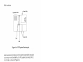
Figure 5-1 illustrates how to configure the SixPakPlus serial port
as COM1 or COM2.
5-1
Advancecl Conliguration
Port enable jumper block
5SiËË:
()(JJJ(9()
Pin CM2-COM2
IRQ lumper block
347
lRo3-coM2
lRQ4-COM1
Pin CM1-COM1
(default posit¡on)
(default position)
Figure 5-1. Serial Port Factory Configuration.
5.1.1 lnstalling Multiple Serial Ports in a PC
lf your PC already has another card with a serial port on it
configured to respond as COMI (such as the PC XT wlth its
standard serial board), you must change the pon on the
SixPakPlus to respond as COM2 as shown in Figure 5-1:
¡
Move the Port Enable Jumper Block shorling plug from
CM1 to CM2.
¡
Move the IRQ Enable Jumper Block shofiing plug from 4
to
3.
The SixPakPlus serial port will now respond as COM2.
5-2
Serial Port
5.1.2 Configuring the RS-232C lnterface Lines
SixPakPlus conforms to the Electronic lndustries Association
(ElA) BS-232C communication standard, which describes the
intedace between DTE and Data Communication Equipment
(DCE). That means that all inputs to an AST serial port (with the
exception of Ring lndicator, pin 221 must be connected to a
signal, even if the connected device does not use one or more of
the interface lines at connector J1.
NOTE
SixPakPlus does not support the current loop
teletype intedace.
ln the default configuration, SixPakPlus expects the connected
device to drive all input signals to its serial ports.
You do not need to change the SixPakPlus default configuratlon
as long as the connected devices drives these serial inputs: Clear
to Send (CTS), Data Set Ready (DSR) and Data Carrier Detect
(DCD). The device's instructions willtell you if it does not drive
these inputs.
lf your serial device does not drive these serial port inputs, you
can configure the SixPakPlus RS-232C jumper block to "force
true" these inputs to the serial port.
The SixPakPlus HS-232C jumper block is divided into three pairs
of jumpers. The first two are labelled DSR for Data Set Ready, the
second two DCD for Data Carrier Detect, and the last two CTS for
Clear to Send. The top jumper of the pair is labelled 1, and it
forces the input true. The bottom jumper of the pair is labelled 2
5-3
Advanced Conf iguralion
and sets the input to normal. To force all of the inputs true, you
would installthe shorting plugs on these pins:
DSR Pin
DCD Pin
CTS Pin
Figure 5-2 illustrates how to force one or more of the above
signals to always be in the true state, Move the corresponding
shorting plug on the RS-232C jumper block (the jumper block
near the top of the SixPakPlus board) from the pair of pins
labelled 2 ("normal") to the pair of pins labelled 1 ("forced true").
For example, to force the DSR input true, move the shorting plug
from position DSR2 to position DSRl.
When you force a signal true, its connection to connector J1 will
not affect the function of the serial porl.
5-4
Serial Port
DSR
lumpers
DCD
jumpers
crs
jumpers
- DSR lorced true
- DSR normal
1 - DCD forced true
2 - DCD normal
1 - CTS forced true
2 - CTS normal
1
2
Normal (default): All input
driven by connected device.
Figure 5-2. Creating a "Forced True" State.
Whether you use the RS-232C jumper block to force certain
inputs true depends on what device you connect to the serial
pott.
You might want to leave the shorting plugs in their "normal"
configuration and instead build a special cable for the serial
device. This would be especially convenient if you will be using
different serial devices on the pon at different times.
5-5
Advanced Conf iguration
Appendix B gives general information on building cables. Also
refer to the manual supplied with your serial device for help in
designing cables.
5.1.3 D¡sabling the SerialPort
You can completely disable the serial port on the SixPakPlus by
removing both of the shorting plugs shown in Figure S-1:
¡
Remove the shorting plugs from positions
on the Port Enable Jumper Block.
o
Remove the shorting plugs from positions 3 or 4 on the
IRQ Enable Jumper Block.
CMl or CM2
You must disable one serial port if your PC already has two serial
poñs installed;this prevents conflicts between multiple ports. Be
sure to save the shorting plugs for possible future use.
5.2 Programm¡ng the Serial Port
The serial pofi on the SixPakPlus is completely under software
control, and must be initialized for correct baud rate, parily,
number of databits, and number of stopbits before it can be used.
You or your software must initialize the serial port each time you
turn on the computer.
Typically, the DOS MODE command initializes the serial port
(refer to your DOS Manualfor a detailed explanation of this
command). A typical MODE command might look like this:
MODE COMI :1200,N,8,1,P < Enter>
The above command initializes serial port COMl for 1200 Baud,
no parity, I databits, and 1 stopbit. The "P" is optional and tells
DOS that you will be using the porl with a serial printer. you can
also use a similar command to establish communication
parameters for serial pon COM2.
5-6
Serial Port
Many applications programs (such as word processors)
automatically handle port initialization, making it unnecessary to
use the MODE command. Refer to your software manual; if it
does not mention the MODE command, it is probably safe to
assurne that you can omit that step. lf you are unsure, it will rrot
harm anything to go ahead and use the MODE command
anyway.
lf you are using the serial port to operate a serial printer, you may
also need to redirect printer output from LPT1 to COMl or COM2.
This is because DOS always assumes that printer output goes to
parallel port LPTI unless told otherwise. You can use the MODE
command to redirect printer output from a parallel port to a serial
port. For example:
For printer output to COMl:
MODE LPT1: = COMl : < Enter>
For printer output to COM2:
MODE LPT1: = COM2: < Enler >
A redirection command should follow the flrst MODE command
that sets up the Baud rate, parity, and so forth. Again, it is
possible that your applications program is handling this
redirectlon automatically. lf so, you can eliminate this step as well.
5.3 Serial !/O Address Ass¡gnments and P¡nouts
The serial port on the SixPakPlus uses the system l/O addresses
and IRQ interrupt request lines shown in Table 5-1.
Table 5-1. l/O Addresses and IRQ lnterrupt Requests.
Port Conliguration
l/O Addresses
IBQ Line
coMl
O3FB-O3FFh
coM2
02F8-02FFh
IRQ4
IBQ3
5-7
Advanced Conf iguration
Table 5-2 gives the pinouts for the SixPakPlus serial pon
connector J1.
Table 5-2. J1 Pinouts.
Jl
Pin
#
1
2
3
4
5
6
7
I
20
22
Signal Name
Chassis Ground
TX (Transmit Data)
RX (Receive Data)
BTS (Request to Send)
CTS (Clear to Send)
DSR (Dataset Ready)
SG (Signal Ground)
DCD (Carrier Detect)
DTR (Data Terminal Ready)
Rl (Ring lndicatofl
Direction
Output
lnput
Output
lnput
lnput
lnput
Output
lnput*
* Ring lndicator connection is not required
5.4 Serial Port Diagnost¡c Testing
Whenever there is any question about the operation of the
SixPakPlus serial port, we recommend that you run the IBM
diagnostics, preferably the advanced diagnostics supplied with
the IBM Hardware Maintenance Manual.
For proper diagnostics operation, disconnect any device
connected to the SixPakPlus serial port (such as a modem or
serial printer). Also, make sure that the CTS, DSR, and DCD
jumpers (Figure 5-21 are in the normal (not "forced true") setting.
You can use a "wrap plug" on the J1 connector to pedorm a very
thorough test of the serial port with the advanced diagnostics. To
build this wrap plug, you need a female DB25S conrrector, such
as a Winchester Electronics P/N 49-1 125S. Jumper the connector
pins as follows:
5-8
Serlal Port
Pln 2 to Pln 3 (IX to RX)
Pln 4 to Pln 5 & 22 (RTS to CTS & Rl)
Pin 20 to Plns 6 & I (DTR to DSR & DCD)
These lumpers are shown ln Figure 5-3.
123
OH
45
oooooo
14 15 16 17 18 19
8i8r¡i38
ooo
23 24 2s
FIgure 5-3. Serial Port Loopback Plug Configuratlon.
When you ready to run the diagnostic program, attach thls plug to
the SixPakPlus' J1 connector. Run the diagnostlc program and
answer the Advanced Diagnoslics loopback plug question wlth Y.
Certaln versions of the IBM dlagnostics may fall on the flrst pass.
You should therefore ignore the results of the first pass if an error
occurs.
5-9
Advanced Conf iguration
NOTES
5-10
PARALLEL PORT
6
The SixPakPlus comes standard with a parallel port for interfacing
the PC to a parallel printer (such as the Epson FX-BST¡{). This port
is completely lBM.compatible wlth the IBM PC and uses the same
female DB25S connector as an lBfil port.
o
Section 6.1 tells you how to conflgure the parallel port.
o
Section 6.2 discusses parallel pofi programming.
r
Section 6.3 gives parallel port l/O address assignments
and pinouts.
¡
Section 6.4 discusses parallel port diagnostic testing.
r
Section 6.5 tells you how to configure your Sixpakplus to
allow interrupt-driven parallel printer software to operate
correctly.
Seclion 3 of this manual tells you how to install the parallel port
ribbon cable onto your SixPakPlus board, and how to install the
board and the parallel port into your PC.
6.1 Configur¡ng the Parallel Port
You can install a maximum of three parallel por.ts in the IBM pC
(called LPT1, LPT2, and LPT3). The parallel porr orr rhe
SixPakPlus has been configured at the factory to respond as
LPTI (LPT2 when a display adapter with a built-in parailel port is
present; see Section 6.1.2l'. You can confirm that the parallel port
is configured as LPTl by checkirrg that a shorting plug is lnstallecl
at position LP1 of the Port Enable Jumper Block (see Figure 6-1).
6-1
Aclvanced Conf iguration
Port Enable Jumper Block
Pin LP1 - LPT1 (Default)
L--
+*
Pin LP2 - LPr2
NOTE: When IBM or AST Monochrome Card
is ¡nstalled, SixPakPlus LPTI automalically
responds as LPT2, and SixPakPlus LPT2
automaticallY resPonds as LPT3.
Figure 6-1. Parallel Port Factory Configurat¡on.
6.1.1 lnstalling Multiple Parallel Ports in a PC
lf your PC already has another card with a parallel port on it
configured to respond as LPTI you must change one of the
boards to respond as LPT2 (this avoids conflicts between the two
ports). Display adapters with a built-in parallel port always
respond as LPT1 and cannot be changed. To reconfigure the
SixPakPlus, move the shorting plug from position LP1 to posltion
LP2 (see Figure 6-1). The parallel port on the SixPakPlus will now
respond as LPT2.
6.1.2 Monochrome Adapter Boards
The built-in parallel port on certain display adapter boards (such
as the IBM monochrome display/printer adapter or the AST
Research MonoGraphPlusrM or Preview!rM) always respond as
LPTI and cannot be changed. lf you have such a board in your
PC, the SixPakPlus parallel port will automatically respond as
LPT2 in lts factory default configuration. Do not reconfigure the
SixPakPlus to respond as LPT2. lf you do reconfigure the
SixPakPlus for LPT2 when a parallel port that always responds as
LPT1 is installed in your PC, the SixPakPlus parallel port will
respond as LPT3.
6-2
Parallel Porl
6.1.3 Disabling the Parallel Port
You can disable the SixPakPlus parallel port by removing the
shorting plug shown in Figure 6-1. You can disable the parallel
port to avoid conflicts when you have several parallel adapters
installed in your PC. Save the shoning plug for possible future
use.
6.2 Programm¡ng the Parallel Port
The IBM PC always sends printer output to parallel porl LPTl
unless specifically told otherwise. Unfonunately, PC-DOS 1.0 and
1.1 do not allow you to redlrect output from one parallel port to
another. Appendix C of this manual tells you how you can cause
the PC to redirect printer output from LPTl to LPT2 or LPT3.
Although it is not required, you can use the DOS MODE
command to set the line width and the number of lines per page.
Refer to your IBM DOS Manual for nrore information.
6.3 Parallel Port l/O Addresses and Pinouts
The SixPakPlus parallel port uses the PC l/O addresses shown in
Table 6-1.
Table 6-1. Parallel Port l/O Addresses.
Port Configuration
LPT1
*
LPf2*
l/O Addresses
0378-037Fh
0278-027Fh
*When you use a display adapter with a built-in parallel port,
the PC sees a SixPakPlus parallel port configured for LPTl
as LPT2, and a SixPakPlus parallel port conflgured for
LPT2 as LPT3.
6-3
Advanced Configuration
You can use the standard IBM Parallel Prlnter Cable to connect
the SlxPakPlus to an IBM or IBM-compatible printer. You can also
use the information ln Table 6-2 to help build a cable for your
parallel prlnter.
Table 6-2. Parallel Port Pinouts.
AST Adapter Cable
Output IBM Matrix Printer
J2 Pin
DB25S Centronics Interface
Line
Name
.STBOBE
DO
D1
D2
D3
D4
D5
D6
D7
-ACK
BUSY
PE
SLCT
-AUTOFD
-ERROR
-INIT
-SLCT IN
GROUND
(q
11
32
53
74
95
11
137
158
179
19
21
23
25
214
415
616
817
1
2
3
4
5
6
6
7
I
9
10
10
11
11
12
13
12
13
14
32
31
12,14,16,
(18-25)
36
(16,1e-30 33)
18,2Q 22,24)
NOTE
A dash in front of the line name denotes lines
which are functionally active when low.
6-4
Parallel Port
6.4 Parallel Port Diagnostic Test¡ng
The parallel port on your SixPakPlus is compatible with the IBM
diagnostics. However, you must configure the parallel port as
LPT1 so that the port can be recognized by the diagnostlcs.
To rurr the diagnostics you must provide incoming signals to the
port by installing a wrap plug in the parallel port connector. To
construct a wrap plug connect the following pins on a DB25P
(male) connector. Use 30AWG (minimum) wire to make the
connections.
Pin 1 to Pin 13
Pin 2 to Pin 15
Pin 10 to Pin 16
Pin 11 to Pin 17
Pin 12 to Pin 14
These jumpers are illustrated in Figure 6-2.
1
2
345
ooo
14151
1
6
7
o o
:
I
o a
19 20
ooo
22 23 24
o
25
Figure 6-2. Parallel Port Loopback Plug
Conliguration.
6-5
Advanced Configuration
NOTE
You cannot peÉorm the IBM diagnostics on the
parallel port if you have installed the IBM
Monochrome Display/Printer Adapter.
lf you run the matrix printer test, your printer must be 100o/o
compatlble with an Epson MX-80 or errors can be generated.
6.5 lnterrupt-Dr¡ven Parallel Printer Software
lnterrupt-driven parallel printer software uses lRQ7. To ensure that
your lnterrupt-driven parallel printer software operates correctly,
you must enable IRQT on the SixPakPlus, as shown in Flgure 6-3.
It wlll not harm anything to enable |RQT even if you do not run
lnterrupt-driven software for your parallel printer.
IRQ Jumper Block
347
Figure 6-3. lRQT Enabled.
6-6
GAME PORT
7
The SixPakPlus game port provides an interface for connecting
one or two joysticks to your PC. With appropriate software, the
joystick can be used for cursor control, as well as graphics
development and interactive games.
This section includes the following:
o
Section 7.1 tells you how to enable or disable the game
pon.
¡
Section 7.2 discusses software compatibility.
r
Section 7,3 gives the l/O address assignment and pinouts
for the game port.
¡
Section 7.4 discusses game poÌl diagnostic testing.
¡
Section 7.5 gives you the information you need to
upgrade the SixPakPlus to add the game port.
7.1 Configur¡ng the SixPakPlus Game Port
To enable the game hardware: The game port ribbon cable must
be installed on your SixPakPlus board (as described in Section 2
of this manual), and the proper shofting plug must be installed on
the Port Enable Jumper Block Pin GME, as shown in Figure 7-1.
The game port hardware must be installed on the board (Sectlon
7.5 provides information on adding the port to your SlxPakPlus).
7-1
Advanced Conf iguration
Port enable jumper block
u¡
=
o
Pin GME
-
Game port enable
(lnstall shorting plug to enable game port.
Remove shorting plug to disable game port.)
Figure 7-1. Game Port Enable/Disable.
To completely disable the SixPakPIus game porf.' Remove the
jumper shown in Figure 7-1.
7.2 Software Compatibility
The game port ls totally software-compatible with the IBM game
adapter. Because joystlcks are analog devices, the functlon of
some software can vary with the loystlck used, even though the
game port is functioning properly. To compensate for differences
7-2
Game Port
between joysticks, use software that includes a joystick centering
function.
You can use tl'ìe program listing in Section 7.4 to test the correct
operation of the SixPakPlus game poñ.
7.3 Game Port Techn¡ca¡ lnformation
This section provides technical lnformation about the Sixpakplus
game pon.
7.3.1 Game Port l/O Address Assignment
The game port uses l/O address 0201h. This information is for
technical reference only; you do not need to kn,-'rur the l/O
address to use the game port.
7.3.2 Game Port Pinouts
The SixPakPlus game port uses a DB155 (socket or female)
intedace connector to enable the connection of up to two
joysticks. Table 7-1 summarizes the game pon pinouts.
7-3
Advanced Conf iguration
Table 7-1. SixPakPlus Game Pofl Pinouts.
SixPakPlus
J3 Pin
Joystick A
No.
DBI5S Pin
Number
1
1
3
5
2
7
I
11
13
15
3
4
5
6
7
I
Signal
Narne
+5VDC
Button 1
X Axis
Ground
Ground
Y Axis
Button 2
+5VDC
Joystick B
2
4
10
+5VDC
Button 1
6
11
X Axis
12
Ground
Y Axis
I
10
12
14
9
13
14
15
Button 2
+5VDC
You can connect one joystick directly to the DB155 connector.
To connect two loysticks, you will need a Y-connector adapter
cable. The adapter cable should have one DB15S connector (to
the SixPakPlus) and two DB15P connectors (to the Joysticks).
Pins 1 through 8 on the DB155 should connect to one DB15P,
and pins 9 through 15 to the other, as shown ln Table 7-1 . Consult
your dealer for further information.
7-4
Game Port
7.4 Game Port Diagnost¡c Testing
You can use the IBM diagnostics to test the SixPakPlus game
adapter poñ. Because of a problem in tlre diagnostic program,
however, the port may not always show up on the listlng of
installed devices. You might prefer to use the program below to
test out the port. This program requires the use of BASICA (not
BASrC).
1O DEFINT A.Z:KEY OFF:CLS:STFiIG ON:SCRËEN 2
20 PRINT " X1"," Y1"r" X2"," Y2"," S1";" 52";" S3"
30 Xl = STICK(O):Y1 = STICK(1):X2 = STICK(2):Y2 = STICK(s)
40 A = STRIG
(1
)
:C = STRIG (s) :C = STRIG (3) :D = STRIG (7)
50 LOCATE 3:PRINT X1,Y1,X2,Y2,4;B;C;D
60 GOTO 30
When you run the above program, moving the joystick in the Xplane (left-right) causes a change in the "X1" readout, while
moving the Joystick in the Y-plane (up-down) causes a change in
the "Y1" readout. Pressing the switch (either one or two,
depending on your joystick) causes a change in the "S1" or "S3"
readouts from 0 to -1. Note that, depending on the quality of your
joystick, you may not be able to get a zero reading in the X and Y
planes when running the program. This is normal and no cause
for alarm.
7.5 Adding the Game Port to Your SixPakPlus
AST Research offers an upgrade kit for field installation of the
SlxPakPlus game porl. To order the game port upgrade kit: order
model number SPK-000G through your AST dealer. The upgrade
kit consists of a 16-pin lC (No. 558CP) and a 20-pin lC (No.
74L5244). To install the game poft, follow the procedure
described below.
7-5
Aclvanced Conf iguration
CAUTION
Be sure the power switch is off and the power
cord is removed from the system unit. Turn off
any other equipment connected to the computer.
lnstalling any component while the power is on
can permanently damage your computer and its
components.
STEP 1
Remove the PC's system unit cover: Follow the instructions in
STEP 1 and STEP 2 of Section 2.3.
STEP 2
Remove deyices attached to the SixPakPlus board: lf you have
installed the parallel pon, remove the the ribbon cable attached to
the SixPakPlus board. Disconnect any serial device connected to
the serial port.
STEP 3
Remove the SixPakPlus boarC: Remove the bracket retaining
screw from the bracket securing the SixPakPlus board to the PC
chassis. With a steady, evenly dist¡ibuted upward tenslon, remove
the SixPakPlus board from its slot.
STEP 4
lnstall the game port lCs: Your game port upgrade kit comes with
two lCs: a 16-pin and a 20-pin lC. Each lC is labelled with a notch
or a small dot to identify the bottom left. lnsefi the lOs as follows.
It is very impoftant that you do not bend arry pins when you lnseft
your lCs.
With the notch (or dot) on the bottom left, insert the 16-pin lC in
socket U37, as shown in Figure 7-2.
With the notch (or dot) on the bottom left, inseft the 20-pin lC in
socket U38, as shown in Figure 7-2.
7-6
Game Port
U37: lnstall 16-pin lC
(No. 558CP) here.
Notch points
away from
bracket
U38: lnstall 20-pin lC
(No. 74LS244) here.
Pin 1 indicator (if present)
in lower left corner
Figure 7-2. lnstalling the Game Adapter Port lCs.
7-7
Advanced Configuration
NOTE
lf the lC seems too wide to allow the pins to
properly line up with their socket receptacles,
place the lC on its side on a flat surface and
gently angle it under both thumbs to slightly
bend the pins inward. You may find this same
technique usefulwhen actually inserting the lC
into the socket on the boarcl. Angle the lC, and
slightly insert one row of pins, then bring the
other row down into position and slightly start its
pins ln the socket. Once you have both sides
started, you can evenly clepress the entire lC until
it is firmly seated.
STEP 5
Enable the game port: Make sure the shorting plug ls lnstalled
across Pin GME of the port enable jumper block, as shown in
Figure 7-1.
STEP 6
Replace the SixPakPlus Board: Follow the instructions in
Section 2.4. Make sure to plug the game pon connector onto
connector J3, as described in STEP 1 of Section 2.4.
STEP 7
Conf igure the game
7-8
port: Follow the instructions in Section 7.1.
PART III. APPENDICES
A. Troubleshootlng and Repalr Procedure
B. Serlallnterface
C. Switchlng Between Parallel Ports
D, lnstalling SlxPakPlus
(r
in the Otder 64-KB IBM pC
NOTES
TROUBLESHOOTING AND
REPAIR PROCEDURE
A
This section outlines some simple procedures for troubleshooting
when you have a problem with your SixPakPlus. lt also describes
the procedure for returning your SixPakPlus to the factory should
it require repairs.
4.1 Troubleshooting
The following outlines some suggestions for solving common
difficulties with the SixPakPlus.
PROBLEM: Power-up Self Test fails.
ACTION: A parity error or interrupt conflict can prevent the self
test from successfully completing. To determine the area of
difflculty, dlsable allfeatures on the SixPakPlus by removlng the
appropriate jumpers plugs on the port enable jumper block (refer
to Figure 2-2l.Then enable each feature one by one, rerunning
the self test each time, until you isolate the problem area.
PROBLEM: Parallel port doesn't work.
ACTION: Check the following:
¡
Check that the device connected to the port works and ls
powered on.
r
Check cabling: Check cables between the parallel port
and peripheral device; check that the ribbon cable to the
parallel pon connector is securely attached to the
SixPakPlus board.
.
Check that the software you are using is sending output
to the correct device. SixPakPlus is usually configured so
that the parallel pon appears as LPTl. Go over the
A-1
Appendices
procedures in Section 6lo make certain the port is
configured as you indented. Check your software to see
to which device it is sending output.
¡
Make sure the parallel pon is enabled. Check that the
shorting plug shown irr Figure 6-1 is installed (Section
6.1 .3).
r
Check that lRQT is enabled (Section 6.5).
PROBLEM: Serial Port doesn't work.
ACTION: Check the following:
¡
Check that the device connected to the serial port ls
powered on and working
¡
Check cabling: check cabling between the serial port and
the peripheral device (see Appendlx B).
¡
Check that the software you are using is sending output
to the correct device. The SixPakPlus is usually
configured so that the serial pon appears as COM1. The
port expects the colìnected device 1o drive all serlal
inputs. Go over the procedures in Section 5.1 to make
ceftain the port is configured as you expect. Check your
software to see to which device it is sending output. lf
you are using a serial prinler, you may need to direct
printer output from LPT1 to COM1 or COM2 (see Section
5.2l..
A-2
¡
Check the jLrmper positions on the'Port Enable Jumper
Block, and the IRQ Jumper Block (Section 5.1).
¡
Make certain the serial port is correctly initialized (Section
5.2). Check that the Baud rate, parity, number of data
bits, and number of stop bits for the peripheral device
match what you specified in your DOS MODE command,
or what your software specified for you.
Troubleshooting
PROBLEM: Game port doesn't work.
ACTION: Check the following:
¡
Check that the device connected to the game port is
powered on and working.
o
Check cabling: check cabling between the game port
and the peripheral device; check that the ribbon cable to
the game port connector is securel)¿ attached to the
SixPakPlus board.
o
Make ceftain the game port is installed and enabled.
Section 7.1 describes the jumper plug that should be
installed, lOs should l¡e installed in sockets U37 and U3B
(Section 7.5).
PROBLEM: Memory errors.
ACTION: Check the following:
¡
Check settings on SixPakPlus switch SW1 (Section 2.2).
o
Check settings on PC system boards (Section 2.3).
o
Perform procedures outlined in Section 4.3,
PBOBLEM: DOS or ASTCLOCK displays incorrect tlme or date.
ACTION: Do the following:
r
Set the correct time and date as described in Section 3.3,
r
Replace the clock-calendar battery (Section 3.4), then
reset the clock (Section 3.3).
A-3
Appendices
4.2 Product Repa¡r Procedure
lf your AST Hesearch product ever requires repair, contact your
dealer first. The dealer from whom you originally purchased the
product can usually service the product. lf you must return a
hardware product to the factory for service, follow these
guidelines to ensure rapid, accurate turnaround:
1.
Call AST Besearc/r Technical Support for a Return
Authorization Number (BAN): A technician will discuss
the problem with you; if factory service is required, the
lechnician will give you a Return Authorizatlon Number
(nAN). Always refer to the RAN when you return anything
for service. AST Research will return anything without a
RAN to the sender.
lf the product is covered under an AST Research
warranty: There is no charge for pans or labor involved ln
the repair. Please include a copy of your original
purchase receipt as the proof of date of purchase for all
warranty repairs.
lf the product is not covered under an AST Besearch
warranty: Contact your dealer or AST Research Technical
Support for further information.
Parts not covered under the warranty: Dealer- or userinstalled parts (such as RAM chips) are not covered
under the terms of the warranty, Dealer-installed pafis are
warranted by the dealer; parts that you install are covered
only by the pafis suppliers' warranties. lf we find that your
dealer or user-installed parts are defective, we can
identify which parts are defeclive, but we will not replace
parts unless you specifically authorize us to do so in
writing when you send the board 1o us. The parts charges
and any applicable labor charges will be billed COD.
Describe the problem and return any related
accessories: Please include a brief but explicit written
description of the problem when you return your AST
A-4
ïroubleshooting
product to the factory for repair. Also return any
accessories that might relate to the problem. For
example, if the the parallel port does not function
correctly, be sure to return the parallel port adapter cable
with the board.
Be sure to provide a return shipping address that UPS
can deliver to and include your RAN: UPS cannot
normally deliver to post office boxes. Beference the RAN
issued to you by AST Technical Support on all
correspondence. Securely package all materials to
prevent shipping damage. Shipping charges must be
prepaid; CODs will not be accepted. Ship the materials to
the following address:
AST Research, lnc.
Customer Service RAN xxxx
2722 Michelson Drive
lrvine, CA 92715
where xxxx is your assigned Return Authorization
Number.
6
Once your product is repaired, we will return it to you by
UPS or UPS Blue Label service, whichever is appropriate
for your geographical location. We will return items
covered by warranty at our expense. Shipping costs
and repair expenses for items not covered by warranty
will be billed COD. lf you prefer overnight service (UPS
Red Label), the shipping charges will be billed COD. lf
you want us to ship Federal Express, please give us your
Federal Express account number for billing purposes.
A-5
Appendices
NOTES
A-6
SERIAL INTERFACES
B
This appendix provides general itformation on wiring the
SixPakPlus serial port to other serial devices (such as printers,
plotters, or modems), including:
¡
The RS-232C serialinterface standard (Section 8.1).
o
lnterfacing DTE to DCE (Section B.2).
¡
lntedacing DTE to DTE -- "null modem" (Section 8.3).
r
Designing your own serial inteface (Section B.4).
The SixPakPlus serial port is completely IBM-compatible. ln mosl
cases, you can connect your remote device to the SixPakPlus
serial port with a cable provided with the device itself. Simply refer
to the instructions provided with the device or with the software
for driving it.
ln some cases, your instructions will specify how your remote
device uses RS-232C line signals and which pin numbers supply
which signals. With this information, plus the information in this
appendix, you can construct an intedace cable yourself.
NOTE
Serialdevices use RS-232C signals in different
ways. AST Research cannot lell you how to
connect a particular device to your serial port.
You must refer to the manufacturer's instructions
that came with that device.
The SixPakPlus serial port does not support the
current loop teletype intedace.
B-1
Appendices
8.1 RS-232C lnterface Standard
SixPakPlus connects to other serial devices according to the
Electronic lndustry Association (ElA) RS-232C intedace standard.
The RS-232C standard describes the sequence of signals that
travel between two serialdevices. The signals controlthe
exchange of data between serial devices. RS-232C defines 20
signals (although few applications use all 20), and each signal
travels separately on a predefined wire.
The RS-232C standard classifies communications devices as:
o
Data terminal equipment (DTE): Equipment associated
wlth the user, such as a PC or a mainframe computer.
The SixPakPlus serial port is a DTE device.
o
Data communications equipment (DCE): Equipment
associated with transmission facilities, such as a modem.
The RS-232C standard describes the ideal case, where a DTE
device connects to a DCE device. Before sending data, the
SixPakPlus serial port must send and receive RS-292C signals in
this order:
Some DCE devices use the Ring lndicator (Hl) signal to
alert SixPakPlus that incoming data is due.
2
SixPakPlus sends Data Terminal Ready (DTH) to signal a
request for a communications link.
3
SixPakPlus receives Data Carrier Detect (DCD) and Data
Set Ready (DSR) -- these signals indicate that the DCE is
ready.
B-2
4
SixPakPlus sends Ready To Send (RTS) -- this signal tells
the DCE that SixPakPlus is ready to send data.
5
SixPakPlus receives Clear To Send (CTS) -- a signal from
the DCE to go ahead and transmit data.
Serial lnterfaces
6.
SixPakPlus then starts transmitting data via the Transfer
Data (TxD) signal. SixPakPlus receives data via the
Receive Data (RxD) signal.
To prevent damage to either device, the chassis ground and
signal ground signals must always be connected. For the
SixPakPlus serial port, connecting to pin 1 or pin 7 or both makes
the connection to chassis ground and sigttal ground.
You can think of certain pins on one side of the intedace as
"functional pairs":
DTE
DCE
DTR
RTS
DSR and DCD
TxD
CTS
RxD
8.2 Interfacing DTE to DCE
An example of a DTE{o-DCE intedace that conforms to the RS232C standard would be to connect the SixPakPlus serial port
(DTE) to a telephone modem (DCE). A correclly configured
DCE/DTE interface is wired straight across: DTE pin 20 wired to
DCE pin 20, pin 2 to pin 2, and so forth.
Two serial devices interact in a ceftain sequence -called
"handshaking" -to function properly:
1.
Some modems (DCE) have an automatic answer mode
that uses the signal Rl to aleft the DTE that incoming data
is due. SixPakPlus (the DTE) would then use DTR to
respond to Rl.
2.
When the SixPakPlus serial port (DTE) wants to send or
receive data it raises the voltage on pin 20; pin 20 carries
the DTR signal. This voltage travels to DCE pin 20 where
the modem interprets it to mean that a communications
link is being requested by the DTE device.
B-3
Appendices
3
lf an open phone line exists, the DCE brings up two lines
on its side of the interface: DSR and DCD.
4
When the DTE sees high voltage at its pins 6 and 8, it can
then bring up pin 4, RTS. RTS tells the DCE that the DTE
has data to transmit to it.
5.
The DCE checks that it is ready to receive data; if so, it
brings up pin 5, CTS.
6
Once the DTE sees voltage on its pin 5, it can transmit
data on the wire connected to pin 2, TxD -or it can
receive data via RxD.
CAUTION
To help protect your equipment from damage, be
sure to connect the ground wires (plns 1 and/or
71.
Figure B-1 shows an ideal DTE{o-DCE interface, including
signals, signal directions, and sequence (top to bottom), The
interface must handle these signals before the DTE can transmit
or receive data:
.
.
B-4
DCD, DSB, CTS, and RxD are input slgnals to the
SixPakPlus.
DTR and RTS are output signals from the SixPakPlus.
Serial lnterlaces
DTE
Signal
Pin #
DCE
Pin #
(Rt)
(Rt)
DTR
Signal
Chassis
Ground
Signal
Ground
Chassis
Ground
Signal
Ground
20
DTR
DCD
DCD
DSR
DSR
RTS
RTS
CTS
CTS
TxD
TxD
RxD
Rxd
Figure B-1. DTE-Io-DCE Interface.
Figure B-1 shows the intedace signals in order of occurrence (top
to bottom). From the DTE's standpoint, it must send DTR, see
DCD, see DSR, send RTS, and see CTS before transmittlng or
receiving data.
The DTE inputs must have voltage applied to them for the
interface to become operational (the DTE outputs are necessary
only because they are inputs to the DCE side of the interface).
The DTE hardware does not release data to the communications
link until it has received the proper set and sequence of signals.
B-5
Appendices
B.3 lnterfac¡ng DTE to DTE ("Null Modem,,)
Many devices (such as serial printers) are set up as DTE. To
output data from the SixPakPlus serial port (also DTE) to another
DTE serialdevice, you must wire a DTE to DTE (or,,null modem")
intedace. A DTE{o-DTE interface is also called a null modem
connection because it does not include a DCE device such as a
modem. Other examples of null modem connections include
connecting two PCs, or connecting a PC to a mainframe.
A null modem interface must provide',response" inputs to either
side of the intedace -- just as if a DCE device were present. The
input voltages to each DTE device must occur in the correct
sequence (the correct sequence varies from device to clevice).
Each side of a null modem intedace acts like the DTE side of a
DTE{o-DCE interface. Both sides of the null modem interface
must send and receive these signals in this sequence before
sending or receiving data:
Send DTR
Receive DCD and DSR
Send BTS
Receive CTS
Figure B-2 shows a standard null modem configuration, including
signal directions and sequence.
B-6
Serial lnterlaces
SixPakPlus
Serial Port
Signal
Pin #
DTE
Other
Serial Port
Pin #
Signal
DCE
1
Ground
7
7
Ground
DTR
20
20
DTR
DCD
I
I
DCD
DSR
6
6
DSR
RTS
4
4
RTS
t
J
Â
¿
2
3
3
Ground
,l
Ground
CTS
TxD
RxD
CTS
TxD
RxD
Figure B-2. Example #1: Null Modem (DTE-Io-DTE)
lnterface.
B-7
Appendices
Figure B-3 illustrates another null modem intedace, including the
direction and sequence of the signals.
SixPakPlus
Seria! Port
Signal
Pin #
DTE
Example
Printer
Pin #
Signal
DCE
Ground
1
1
Ground
Ground
7
7
Ground
DTR
20
20
DTR
DCD
B
I
DCD
DSR
6
6
DSR
RTS
4
4
RTS
CTS
5
5
CTS
TxD
2
2
TxD
RxD
3
3
RxD
Figure B-3. Example #2: Null Modem lnterface.
Notice that the necessary input signals are supplied to both sides
DCD, DSR, and CTS have voltage applied to them on either sicle.
The example shown in Figure B-3 changes the ideal sequence by
having the printer DTR signal drive PC signal CTS. The chip rhat
B-8
Serial lnterfaces
controls the SixPakPlus serial port (an 8250 UART chip) is fairly
flexible in reading the sequence of inputs.
The input sequence in Figure B-3 is changed because the printer
in the example drops its DTR signal when its receive buffer is
about to fill up. To avoid losing data when the printer's receive
buffer ovedlows, the intedace halts PC data output immediately
by dropping the CTS input to the PC side immediately. The
remainder of the interface then "idles" until the printer raises DTR
again. Remember that this is a specific case for this particular
printer.
Figure B-4 shows another example of lrow to interface a serial
printer to a SixPakPlus serial port.
B-9
Appendices
SixPakPlus
Serial Port
Signal
Pin #
DTE
Other
Serial Port
Pin
#
Signal
DCE
Ground
I
I
Ground
Ground
7
7
Ground
2Q
20
DTR
DCD
B
(J
DCD
DSR
6
6
DSR
RTS
4
19
SRTS
CTS
5
C
CIS
TxD
2
RxD
J
DTR
TxD
J
RxD
Figure B-4. Example #3: Null Modem Interface.
ln this case, the printer uses SRTS (Secondary Request to Send,
pin 19) lnstead of pin 4 (RTS); apart front that exception, Figure
B-3 follows the ideal DTE lnput and sequence rules.
The advantage of the interface shown in Figure B-4 is that every
pin is driven by its functional counterpaft on the other slde of the
intedace; the functionally related signal pairs include DTR/DSR,
RTS/CTS, and TxD/RxD. This should also hold true for the
interface you design.
B-10
Serial lnterfaces
8.4 Design A¡ds
Your serial device manual tells you how the device uses the
RS-232C line signals and which pirr numbers supply which
signals. You can also contact the device manufacturer for fufther
information on interfacing to an IBM PC asynchronous serial porl.
Serial ports on allAST Research boards are IBM-compatible.
Your dealer can direct you to a parts store that carries the
products you need to construct an intedace cable. You must use
the correct type of 25-pin connectors (male or female) to connect
both ends properly. The SixPakPlus serial port end plugs into a
DB25S (female/socket type) connector.
To wire your serial intedace signals properly, we suggest you use
the form shown in Figure B-5 as a design aid.
B-11
Appendices
AST Serial Port
IBM PC Side
Signal
Pin #
Serial Peripheral
Device
Pin
#
Signal
Ground
1
Ground
Ground
7
Ground
Output
lnput
lnput
DTR
20
DCD
DSR
6
Output
RTS
4
lnput
CTS
5
Data
Out
TxD
2
Data
ln
RxD
J
Figure B-5. Serial Interface Form.
lf you plan to use several different serial devices on your serial
port, you can make a separate intedace assembly for each
devlce. That way you can use the same long cable to connect
your PC to any of these devices.
B-12
SWITCHING BETWEEN PARALLEL
PRINTER PORTS
c
This appendix gives you programs you can use in a batch file to
direct printer output normally designated for the device attached
to port LPT1, to instead be routed to the device attached to port
LPT2 or LPT3. (The program also directs output, normally
designated for the device attached to port LPT2 or LPTO, to
instead be routed to the device attached to port LPT1.) For more
information on creating a batch file, see your IBM DOS Manual.
The programs in this appendix are parlicularly useful if your
applications program (a word processing program, for example)
ls capable of sendlng print output to only one parallel port. You
might also use this program when your LPTI printer (call it printer
#1) is down for seruice, or when you want to take advantage of
the type style or speed of the printer attached to LPT2 or LPT3
(call it printer #2 or #3). This program allows you to quickly
switch between outputs without having to alter your hardware
inteÍace or change each line in programs where LPT1, LPT2, or
LPT3 appear as your output port designation.
lf your prlnters are not configured to the same parameters, as
defined in the DOS MODE command, you must add two MODE
statements when switching devices.
Notice that the "swap" program below is written in BASIC. Since
the printer port swap is best handled in DOS, BASIC is invoked
within the .BAT file. No RUN command ls required when the
BASIC call and the program file name occur on the same line
(BASIC LPTSWAP). Consult your IBM BAS/C Manualif you have
any questions about entering and saving the LPTSWAP.BAS
program.
c-r
Appenclices
C.1 Switching Between LPTI and LPT2
The following DOS batch file and BASIC program redirects printer
output from LPTI to LPT2 or vice versa, depending on which port
is being used at the time.
LPTSWAP.BAT (or a name of your choosing) with the following:
MODE LPT1:[parameters lor printer +2 (if needed)l
MODE LPT2:[parameters lor pr¡nter #1 (if needed)]
BASIC LPTSWAP
LPTSWAP is a BASIC program, as shown below. The comments
are lncluded for clarification and need not be included in the
actualprogram.
10 DEF SEG =
&H40
20 A= PEEK (8): B= PEEK
'
(9)
30 POKE I,PEEK (10): POKE 9,PEEK
40 POKE 10,4: POKE
50
11,8
SYSTËM
flnds port address table
'save LPTI address
(1
1)
' LPT2 address to LPT1
'LPT1 addressto LPT2
'return to DOS
Omit statement 50 if you will be LPR|NTing from BASIC.
C.2 Restoring LPTI to LPT1 and LPT2 to LPT2
Use the same program, LPTSWAP, to restore your parallel printer
ports to their original arrangement. Be sure to restore the proper
parameters uslng a new batch file and MODË statements.
LPTRSTR.BAT is as follows:
MODE LPT1:[parameters lor printer #1 (if needed)l
MODE LPT2:[parameters lor pr¡nter #2 (if needed)]
BASIC LPTSWAP
c-2
Switching Between Pafallel Pofts
C.3 Switching Between LPTI and LPT3
The following DOS batch file and BASIC program redlrects printer
output from LPT1 to LPT3 or vice versa, dependlng on which port
is being used at the time.
LPTSWAP.BAT (or a name of your choosing) with the following:
MODE LPT1:[parameters for printer #3 (if needed)]
MODE LPT3:[parameters lor pr¡nter #t (if needed)l
BASIC LPTSWAP
LPTSWAP is a BASIC program, as shown below. The comments
are included for clarification and need not be included in the
actual program:
10 DEF
SEG:
&H40
B=PEEK(9)
'finds port address table
'saveLPTIaddress
20A:PEEK(8):
30 POKE I,PEEK (12): POKE I,PEEK
40 POKE 12,A: POKE
50
13,8
SYSTEM
(13)
' LPTS address to LPT1
' LPT1 address to LPTS
'return to DOS
Omit statement 50 lf you will be LPR|NTing from BASIC.
C.4 Restoring LPT1 to LPTI and LPT3 to LPT3
Use the same program, LPTSWAP, to restore your parallel printer
ports to their original arrangement. Be sure to restore the proper
parameters using a new batch file and MODE statements.
LPTRSTR.BAT is as follows:
MODE LPTl:[parameters for pr¡nter #t (if needed)]
MODE LPT3:[parameters lor printer #3 (if needed)]
BASIC LPTSWAP
c-3
Appendices
NOTES
c-4
INSTALLING SIXPAKPLUS IN THE
OLDER 64-KB IBM PC
D
This appendix provides instructions for configuring and installlng
SixPakPlus if you have an original (64 kilobyte (KB) system board)
IBM PC.
Def inition: The original PC has 64 KB of memory on its system
board. The system board switches on the 64-KB PC can be set for
a maximum oÍ 544 KB. However, it is possible to install up to 640
KB in the 64-KB PC; you must installthe IBM BIOS ROM Upgrade
Kit (lBM P/N 1S01005) to enable a full 640 KB to be recognlzed.
Conf iguration and installafion: Follow this procedure to conflgure
and install SixPakPlus in the older PC:
STEP
1
Conf igure SixPakPlus f or the start¡ng address (64 KB), the
amount of SixPakPlus memory, and parity check enableldisable.
Section 2 tells you how to configure the SixPakPlus.
The only special instruction for the 64-KB PC ls that the
SlxPakPlus staning address is always 64 KB (unless another
memory expansion board is installed startlng at 64 KB). lf another
memory board is installed starting at 64 KB, set the SixPakPlus
starting address at the end of installed memory.
STEP 2
Open the PC. Section 2 (as wellas the IBM PC Guide ro
Operatlons) tells you how to open the PC. The procedure for
openlng the original PC ls the same as for the latter (2S6-KB
system board) PC.
STEP 3
Sef the PC system board switches for the total amount of
memory and the number of disk drives (if you are adding
SuperDrive). Set switch SW2 (shown ln Flgure D-1) on the system
D-1
Appendices
board for the total amount of memory in the PC (including system
memory and all expansion memory).
Memory SW2-1 SW2-2 SW2-3
64 KB
ON
ON
ON
128 KB
ON
OFF
ON
192 KB
ON
ON
OFF
256 KB
ON
OFF
OFF
320 KB
ON
ON
ON
384 KB
ON
OFF
ON
448 KB
ON
ON
OFF
512 KB
ON
OFF
OFF
544 KB
OFF
OFF
OFF
Total
SW2-4
ON
ON
ON
ON
OFF
OFF
OFF
OFF
OFF
Figure D-1. Switch Setting SW2lor Total Memory in
the PC.
Some applications programs available for the PC do not work
correctly when the su¡itches are set lor 544 KB. You should
therefore use the 512-KB setting even if you have more than 512
KB installed in your 64-KB PC. SuperDrive and SuperSpool (as
well as cefiain other programs) can still use the excess beyond
the 512-KB setting.
lf your original PC is equipped with the IBM Expansion Unit and
has the new read-only memory basic input output system (ROM
BIOS) installed, you can address a full 640 KB, and you should
use the switch settings for the latter (256-KB) PC (see Section 2).
Set SW-1 (Figure D-2) on the system board for the number of disk
drives (including floppy and SuperDrives).
D-2
lnstalling SixPakPlus in a 64-KB IBM PC
IBM
Number
of Drives
uperDrive
tions
System Board
Switch SW1
ffi
ffi
ffi
ffi
Fixed Disk
A:
C:
A:B:
C:
A:B:C:
D:
A:B:C:D:
E
Figure D-2. Switch Setting SWI for Number of Disk
Drives (lf Installing SuperDrive).
STEP 4
lnstall the SixPakPlus board in your PC. The procedure for
installing SixPakPlus in the older 64-KB PC is the same as for the
later (256-KB system board) PC.
Troubleshooting Memory Problems: The troubleshootirrg
procedure for memory problems (described in Section 4.3) is the
same for the 64-KB PC as for other PCs.
D-3
Appendices
The only special point to remember is that the first 64-KB memory
bank (Bank 0) in your PC willalways be system memory. All other
memory banks will then refer to expansion memory.
For example, if you have a 64-KB PC that includes a SlxPakPlus
with 384 KB of memory:
Bank 0 ls on the system board.
Banks 1 through 6 are on the SlxPakPlus.
An error message llke "3020 20 7" would polnt to the fourth bank in
an 64-KB PC. Bank 0 ls on the system board. Banks 1 and above
are on the SlxPakPlus. The fourth bank ln the PC ls the third bank
on the SixPakPlus.
D-4
LIMITED WARRANTY
AST Research, Inc. n'arrants to the original purchaser of this AST
Research, Inc. product that it is to be in good working order for
a period of 2 years from the date of purchase from AST Research,
Inc. or an authorized AST Research, Inc. dealer. Should this
¡'rroduct, in AST Research, Inc.'s opinion, malfunction during the
rvarrantv period, AST lvill, at its option, repair or replace it at no
charge, providecl that the product has not been subjected to nisuse,
abuse, or r-ron-AST authorized alterations, modifications, and/or
repairs.
Products rerluiring Limited Warrarrty service during the war.ranty
period should be delivered to AST n'itlr proof of purchase. If the
deliverv is bv nail, \'ou agree to insure the product or assunre risk
of loss or damage irr transit. You also agree to prepay shipping
charges to AST.
ALL EXPRESS
AND IMPLIED WARRANTIES FOR THIS
PRODUCT INCLUDING, BUT NOT LIMITED TO, THE
WARRANTIES OF MERCFIANTABILITY AND FITNESS FOR A
PARTICULAR PURPOSE ARE LIMITED IN DURATION TO THE
ABOVE 2 YEAR PERIOD. Sonre states do rrot allow limitations on
hort long an implied n'arrantv lasts, srt the above linritations nray
not apply ttl 1,1'¡¡-,.
UNDER NO CIIìCUMSTANCES WILL AST RESEARCH, INC.
BE LIABLE IN ANY WAY TO THE USER FOR DAMAGES,
INCLUDING ANY LOST PROFITS, LOST SAVINGS OR OTHER
INCIDENTAL OR CONSEQUENTIAL DAMAGES ARISING OUT
OF THE USE OF, OR INABILITY TO USE, SUCH PRODUCT.
Sonre states do uot allon, tlre exclusiolr or linritation of inciderrtal
()r c()ltsecluerrtial danra¡¡es frtr consuller'
¡rrodtrcts, so the .rbove linritations or exclusiolr rìlay n()t alrfrly to vtlu.
THIS WARRANTY CIVES YOU SÍ)ECIFIC LECAL RIG}JTS, AND
YOU MAY ALSO HAVE OTI{ER IìIG}ITS WTJICH MAY VARY
FROM STAIE TO STATE.
The linrited rvarrantv a¡r¡rlies kl lrardn,are products only.
AST RESEARCH, INC.
Product Comment Form
SixPakPlus@
User's Manual
000490-001 A
We appreciate your comments regarding any problems or
suggestions related to AST Research products. Please use
this form to communicate any observations that you have
concerning the improvement of either the product itself or
the product documentation provided in this manual.
Submitter lnformation
Submitter's name:
Address:
Product/Manual Comments and Suggestions
Please mail this form to:
AST Research, lnc.
Attn: Product Marketing
2121 Alton Ave.
lrvine, CA 92714-4992
o
o
o