1
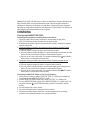
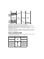
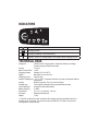
MULTI US 3300
Battery Charger
For lead-acid batteries 2–90Ah
User Manual and Guide to professional
charging of starter and deep cycle batteries.
US
INTRODUCTION
The MULTI US 3300 is a primary switch mode battery charger with pulse maintenance.
The MULTI US 3300 is designed to offer maximum life for the battery. MULTI US 3300 is
a member of a family of professional chargers from CTEK SWEDEN AB. It represents the
state-of-the-art of today’s technology for battery charging. Please read these operating
instructions carefully before operating the MULTI US 3300.
IMPORTANT SAFETY INSTRUCTIONS
California Proposition 65
WARNING: This product contains chemical known to the state of California to cause
cancer or reproductive toxicity.
1. SAVE THESE INSTRUCTIONS – This manual
2.
3.
4.
5.
6.
7.
8.
9.
10.
contains important safety and operating instructions for battery charger models
MULTI US 3300.
When charging, batteries can emit explosive gases, therefore it is essential
WRSUHYHQWÀDPHVDQGVSDUNV7KHFKDUJHULVGHVLJQHGIRUFKDUJLQJOHDGDFLG
batteries from 2 to 90Ah. Do not use for any other purpose.
Always provide good ventilation when charging.
Use of an attachment not recommended or sold by the battery charger
PDQXIDFWXUHUPD\UHVXOWLQDULVNRI¿UHHOHFWULFVKRFNRULQMXU\WRSHUVRQV
To reduce risk of damage to electric plug and cord, pull by the plug rather than cord
when disconnecting charger.
An extension cord should not be used unless absolutely necessary. Use of
LPSURSHUH[WHQVLRQFRUGFRXOGUHVXOWLQDULVNRI¿UHDQGHOHFWULFVKRFN,IDQ
extension cord must be used, make sure that: a) Pins on plug of extension cord are
the same number, size and shape as those of plug on charger; b) Extension cord is
properly wired and in good electrical condition; and c) Wire size is large enough for
DFDPSHUHUDWLQJRIFKDUJHUDVVSHFL¿HGLQ³WHFKQLFDOGDWD´
Do not operate charger with damaged cord or plug – return the charger to the
place where purchased.
Never operate the charger if it has received a sharp blow, been dropped or
RWKHUZLVHGDPDJHGLQDQ\ZD\WDNHLWWRDTXDOL¿HGVHUYLFHPDQ
'RQRWGLVDVVHPEOHFKDUJHUWDNHLWWRDTXDOL¿HGVHUYLFHPDQZKHQVHUYLFHRU
repair is required. Incorrect reassembly may result in a risk of electrical shock or
¿UH
To reduce risk of electric shock, unplug charger from AC outlet before attempting
any maintenance or cleaning. Turning off controls will not reduce the risk.
11. WARNING - RISK OF EXPLOSIVE GASES
a) WORKING IN VICINITY OF A LEAD-ACID
BATTERY IS DANGEROUS. BATTERIES
GENERATE EXPLOSIVE GASES DURING
NORMAL BATTERY OPERATION. FOR THIS
REASON, IT IS OF UTMOST IMPORTANCE
THAT, YOU FOLLOW THE INSTRUCTIONS
EACH TIME YOU USE THE CHARGER.
b) To reduce risk of battery explosion, follow these instructions and those published
by the battery manufacturer and the manufacturer of any equipment you intend
to use in vicinity of battery. Review cautionary marking on these products and on
engine.
12. PERSONAL PRECAUTIONS
a) Consider have some one close enough by to come to your aid when you work near
a lead-acid battery.
b) Have plenty of fresh water and soap nearby in case battery acid contacts skin,
clothing or eyes.
c) Wear complete eye protection and clothing protection. Avoid touching eyes while
working near battery.
d) If battery acid contacts skin or clothing, wash immediately with soap and water.
,IDFLGHQWHUVH\HLPPHGLDWHO\ÀRRGH\HZLWKUXQQLQJFROGZDWHUIRUDWOHDVW
minutes and get medical attention immediately.
e) 1(9(5VPRNHRUDOORZDVSDUNRUÀDPHLQYLFLQLW\RIEDWWHU\RUHQJLQH
f) Be extra cautious to reduce risk of dropping a metal tool onto battery. It might spark
or short-circuit battery or other electrical part that may cause explosion.
g) Remove personal metal items such as rings, bracelets, necklaces, and watches
when working with lead-acid battery. A lead-acid battery can produce a short-circuit current high enough to weld a ring or the like to metal, causing a severe burn.
h) Use charger for charging a LEAD-ACID battery only. It is not intended to supply
power to a low voltage electrical system other than in a starter-motor application.
Do not use battery charger for charging dry-cell batteries that are commonly used
ZLWKKRPHDSSOLDQFHV7KHVHEDWWHULHVPD\EXUVWDQGFDXVHLQMXU\WRSHUVRQVDQG
damage to property.
i) Never charge a frozen battery.
13. PREPARING TO CHARGE
a) If necessary to remove battery from vehicle to charge, always remove grounded
WHUPLQDOIURPEDWWHU\¿UVW0DNHVXUHDOODFFHVVRULHVLQWKHYHKLFOHDUHRIIVRDV
not to cause an arc.
b) Be sure area around battery is well ventilated while battery is being charged.
c) Clean battery terminals. Be careful to keep corrosion from coming in contact with
eyes.
d) $GGGLVWLOOHGZDWHULQHDFKFHOOXQWLOEDWWHU\DFLGUHDFKHVOHYHOVSHFL¿HGE\EDWWHU\PDQXIDFWXUHU'RQRWRYHU¿OO)RUDEDWWHU\ZLWKRXWUHPRYDEOHFHOOFDSVVXFK
as valve regulated lead acid batteries, carefully follow manufacturer’s recharging
instruction.
e) 6WXG\DOOEDWWHU\PDQXIDFWXUHU¶VVSHFL¿FSUHFDXWLRQVZKLOHFKDUJLQJDQGUHFRPmended rates of charge.
f) Determine voltage of battery by referring to car owner’s manual and make sure that
WKHRXWSXWYROWDJHVHOHFWRUVZLWFKLVVHWDWFRUUHFWYROWDJH,IFKDUJHUKDVDGMXVWDEOH
charge rate, charge battery initially at lowest rate.
14. CHARGER LOCATION
a) Locate charger as far away from battery as dc cables permit.
b) Never place charger directly above battery being charged; gases from battery will
corrode and damage charger.
c) 1HYHUDOORZEDWWHU\DFLGWRGULSRQFKDUJHUZKHQUHDGLQJHOHFWURO\WHVSHFL¿FJUDYLW\
RU¿OOLQJEDWWHU\
d) Do not operate charger in a closed-in area or restrict ventilation in any way.
e) Do not set a battery on top of charger.
15. DC CONNECTION PRECAUTIONS
a) Connect and disconnect dc output clips only after setting any charger switches to
³RII´SRVLWLRQDQGUHPRYLQJDFFRUGIURPHOHFWULFRXWOHW1HYHUDOORZFOLSVWRWRXFK
each other.
b) Attach clips to battery and chassis as indicated in 16(e), 16(f), 17(b) through 17(d).
16. FOLLOW THESE STEPS WHEN BATTERY
IS INSTALLED IN VEHICLE. A SPARK
NEAR BATTERY MAY CAUSE BATTERY
EXPLOSION. TO REDUCE RISK OF A SPARK
NEAR BATTERY:
a) Position AC and DC cords to reduce risk of damage by hood, door or moving
engine part.
b) 6WD\FOHDURIIDQEODGHVEHOWVSXOOH\VDQGRWKHUSDUWVWKDWFDQFDXVHLQMXU\WR
persons.
c) Check polarity of battery posts. POSITIVE (POS, P, +) battery post usually has
larger diameter than NEGATIVE (NEG, N, -) post.
d) Determine which post of battery is grounded (connected) to the chassis. If negative post is grounded to the chassis (as in most vehicles) see (e). If positive post is
grounded to the chassis, see (f).
e) For Negative-grounded vehicle, connect POSTIVE (RED) clip from battery charger to POSITIVE (POS, P, +) ungrounded post of battery. Connect NEGATIVE
(BLACK) clip to vehicle chassis or engine block away from battery. Do not connect
clip to carburetor, fuel lines, or sheet-metal body parts. Connect to a heavy gage
metal part of the frame or engine block.
Charger connection.
1. Connect positive charger clip (red) to positive battery terminal.
2. Connect negative charger clip (black) to a good metal engine ground away from
the battery. Do no connect clip to fuel lines or sheet-metal body parts.
3. Connect the AC cord to the socket. The red alarm indication light will indicate
a battery which is connected to reverse polarity.
f) For Positive grounded vehicle, connect NEGATIVE (BLACK) clip from battery
charger to NEGATIVE (NEG, N, –) ungrounded post of battery. Connect POSITIVE
(RED) clip to vehicle chassis or engine block away from battery. Do not connect
clip to carburetor, fuel lines, or sheet-metal body parts. Connect to a heavy gage
metal part of the frame or engine block.
Charger connection.
1. Connect negative charger clip (black) to negative battery terminal.
2. Connect positive charger clip (red) to a good metal engine ground away from the
battery. Do no connect clip to fuel lines or sheet-metal body parts.
3. Connect the AC cord to the socket. The red alarm indication light will indicate
a battery which is connected to reverse polarity.
g) When disconnecting charger, turn switches to off, disconnect AC cord, remove clip
from vehicle chassis, and then remove clip from battery terminal.
h) See operating instructions for length of charge information.
17. FOLLOW THESE STEPS WHEN BATTERY
IS OUTSIDE VEHICLE. A SPARK NEAR
BATTERY MAY CAUSE BATTERY
EXPLOSION. TO REDUCE RISK OF
A SPARK NEAR BATTERY:
a) Check polarity of battery terminals. POSITIVE (POS, P, +) battery post usually has
a larger diameter than NEGATIVE (NEG, N, -) post.
b) Attach at least a 24-inch-long 6-gauge (AWG) insulated battery cable to
NEGATIVE (NEG,N,–) battery post.
c) Connect POSITIVE (RED) charger clip to POSITIVE (POS, P, +) battery of post.
d) Position yourself and free end of cable as far away from battery as possible – then
connect NEGATIVE (BLACK) charger clip to free end of cable.
e) 'RQRWIDFHWKHEDWWHU\ZKHQPDNLQJWKH¿QDOFRQQHFWLRQ
f) When disconnecting charger, always do so in reverse sequence of connecting
SURFHGXUHDQGEUHDN¿UVWFRQQHFWLRQZKLOHDVIDUDZD\IURPEDWWHU\DVSUDFWLFDO
g) When disconnecting charger, disconnect in reverse sequence from connecting
procedure. See operating instructions for charge information.
h) A marine (boat) battery must be removed and charged on shore. To charge it on
board requires equipment specially designed for marine use.
The battery charger must be connected to the battery according to
the instructions above.
IMPORTANT SAFETY INFORMATION!
The MULTI US 3300 cannot be used to restore a fully worn out battery.
If the MULTI US 3300 does not switch to maintenance charge after three days (green light
illuminated), there is a fault. Possible causes:
• The battery is probably worn out and should be replaced.
• Some large antimony batteries may behave different and can allow the MULTI US 3300
to charge the battery for too long, which can lead to overcharging. See caution!
• ,IKHDY\SRZHUFRQVXPHUVOLNH¿WWHGDODUPVDQGQDYLJDWLRQFRPSXWHUVDUHFRQQHFWHGWR
the battery, the charging process takes longer and this can also overcharge the battery.
• $VXOSKDWHGEDWWHU\ZLOORQO\DFFHSWFXUUHQWZLWKGLI¿FXOW\DQGFRQVHTXHQWO\WKHFKDUJing process takes a particularly long time. A worn out battery cannot be fully charged.
Therefore you should always check whether the charger has been switched to maintenance charge before you leave it turned on or unobserved for any length of time.
Caution: If the MULTI US 3300 does not switch to maintenance charge mode after three
days, manually switch it to pulse maintenance mode. If the set has been switched to
maintenance charge, then everything is in order. Note: A battery that hasn’t changed to
maintenance charge after three days is most likely worn out and needs to be replaced. All
other batteries can be maintained for a very long time.
CHARGING
Connecting the MULTI US 3300:
&RQQHFWLQJWKHHTXLSPHQWWRDEDWWHU\ÀWWHGLQWKHYHKLFOH
1. When the battery cable is being connected or disconnected, the plug of the
MULTI US 3300 must be disconnected from the power socket.
2. Establish which terminal is ground (connected to the chassis). Normally the negative
terminal is grounded.
3. Charging a battery grounded to the negative terminal: Negative-grounded vehicle
Charger connection.
a) Connect positive charger clip (red) to positive battery terminal.
b) Connect negative charger clip (black) to a good metal engine ground away from the
battery. Do not connect clip to fuel lines or sheet-metal body parts.
c) Connect the AC cord to the socket. The red alarm indication light will indicate a
battery which is connected to reverse polarity.
4. Charging a battery grounded to the positive terminal: Positive grounded vehicle
Charger connection.
a) Connect negative charger clip (black) to negative battery terminal.
b) Connect positive charger clip (red) to a good metal engine ground away from the
battery. Do not connect clip to fuel lines or sheet-metal body parts.
c) Connect the AC cord to the socket. The red alarm indication light will indicate a
battery which is connected to reverse polarity.
Connecting the MULTI US 3300 to an out of vehicle battery:
1. Check polarity of battery terminals. POSITIVE (POS, P, +) battery post usually has
larger diameter than NEGATIVE (NEG, N, -) post.
2. Connect POSITIVE (RED) charger clip to POSITIVE (POS, P, +) battery post.
3. Connect NEGATIVE (Black) charger clip to NEGATIVE (NEG, N, -) battery post. The
red alarm indication light will indicate a battery, which is connected to reverse
polarity.
4. Connect charger’s AC cord to socket.
5. 'RQRWIDFHWKHEDWWHU\ZKHQPDNLQJWKH¿QDOFRQQHFWLRQ
6. When disconnecting charger, disconnect in reverse sequence from connecting
procedure. See operating instructions for charge information.
Starting the charging process
1. 6HWWKHFRUUHFWFKDUJHPRGHE\SUHVVLQJWKHPRGHEXWWRQ<RXFDQ¿QGRXWKRZWR
select the correct charge mode to be used for charging your battery in the section on
³6(77,1*6´
2. Once you have established that the battery cable has been correctly connected you
can start the charging process. To do so, insert the charger plug into the AC socket.
3. Now either the charge indicator
or the maintenance charge indicator
lights
up. When the maintenance charge indicator lights up, the battery is fully charged. If
the battery voltage drops, the charger sends a pulse to the battery. The length of the
pulse depends on how much charge the battery has lost. The MULTI US 3300 may be
connected for months at a time. However it is recommended to monitor batteries on
charge.
4. If nothing happens: If the indicator for the set voltage is still illuminated, but no other
indicator is illuminated, the connection to the battery or the chassis could be faulty, or
the battery could be defective. If the charging process has not started, this could be
due to the fact that the power socket is not supplying a current.
5. The charging process can be interrupted at any time. In addition pull the plug of the
charger out of the power socket or put the charger on Stand-by/Power On . Always
remove the plug of the charger from the power socket before disconnecting the battery
FDEOH,I\RXLQWHUUXSWWKHFKDUJLQJSURFHVVRIDEDWWHU\¿WWHGLQDYHKLFOHWKHEDWWHU\
FDEOHPXVWDOZD\VEH¿UVWGLVFRQQHFWHGIURPWKHFKDVVLVDQGWKHQIURPWKHRWKHU
battery cable.
6. If the indicator for charge
and maintenance charge DUHÀDVKLQJDOWHUQDWHO\WKLV
may have the following causes:
• Interruption of the charging process because a cable has become loose or because
the battery is not conducting.
• 7KHEDWWHU\LVVXOSKDWHG,IWKHLQGLFDWRUÀDVKHVIRUPRUHWKDQPLQXWHVWKHEDWWHU\
may be defective and should be replaced.
• ,IWKHÀDVKLQJVLJQDOLVÀDVKLQJDWLQWHUYDOVRIPRUHWKDQVHFRQGVWKHQWKHUHLVD
high self discharge of the battery, indicating a bad battery.
BATTERY TYPES AND SETTINGS
MULTI US 3300 can easily be set for different types of batteries or conditions. The following recommendations should however only be seen as guidelines. Please consult the
battery manufacturer for further instructions.
6HWWLQJVDUHPDGHE\SUHVVLQJWKH´02'(EXWWRQ´DQGVWHSSLQJIRUZDUGRQHSUHVVDWD
time until the required mode is reached, the button is then released. The selected mode is
saved in a memory in the charger and remains there even if the charger is switched off.
Mode 14.4V/0.8A
This mode is normally used for batteries <14Ah.
Mode 14.4V/3.3A
Normal setting for wet batteries, maintenance free and for most Gel batteries.
Some gel batteries prefer a slightly lower voltage. Please consult the battery
manufacturer when in doubt.
Mode 14.7V/3.3A
This setting is recommended for a battery at temperatures <41°F. It is also
recommended for many AGM batteries like Optima, Maxxima and Odysses.
Consult your battery manufacturer when in doubt.
CHARGING CYCLE
MULTI US 3300 operates in a four step fully automatic cycle. It starts the charging with
an almost constant current (0.8A or 3.3A) until maximum voltage (14.4V or 14.7V) is
reached. At this point the charger switches to constant voltage, and the current supply
to the battery is gradually reduced. If the current drops to 0.4A, the charger switches to
pulse maintenance. If the battery is charged and the terminal voltage of the battery falls to
9WKHFKDUJHUDXWRPDWLFDOO\VWDUWVDJDLQDWWKH¿UVWVWHSRIWKHFKDUJHFKDUDFWHULVWLF
The MULTI US 3300 measures both voltage and current in order to determine out whether
WKHFKDUJLQJSURFHVVLV¿QLVKHGRUZKHWKHUDQHZFKDUJLQJF\FOHPXVWEHVWDUWHG9DULRXV
methods are used, depending on the time of the measurement; see table:
When?
Reading
Yes
No
Before the start or
after changing the
charging mode.
Voltage higher than
12.9V?
Green indicator lit
until the voltage
<12.9V.
Orange indicator,
charging process.
During the charging
process.
Current greater than Orange indicator,
0.4A?
charging process.
Green indicator
illuminated until the
voltage <12.9V.
Desulphation: Desulphation with pulsing for sulphated batteries.
Bulk: Charging where about 80% of the energy is returned. The charger delivers an
almost constant current until the battery voltage reaches the set level.
Absorption: Charging up to almost 100%. The charge current tapers and the voltage is
kept constant at the set level.
Pulse: Maintenance charge. The charging process ranges between 95% and 100%. The
battery receives a pulse if the voltage falls. This stage will keep your battery in a good
condition if it is not being used.
BULK CHARGING TIME
The table shows the duration of the Bulk step up to about 80% state of charge. The time
for the Absorption should be added.
Battery size (Ah)
Mode
Time (h)
2
2–3
8
8–10
14
3–4
50
12–14
90
23–26
INDICATORS
Incorrect polarity.
Charging process
Charging completed. Pulse maintenance.
Standby / Power on. Charger ready to use, please select charging function.
TECHNICAL DATA
Voltage AC
120VAC, 60Hz. Output power is reduced at lower input voltage.
A perfect charge will still be achieved.
Current
1.1A rms
Back Current Drain* 1.3mA
Charging Voltage
Nominal: 12V 14.4/14.7V
Ripple**
Max 50mV rms, max 0.13A.
Charging Current
0.8/3.3A max
Ambient Temperature - 4°F to +122°F. Automatic reduction of power at increased ambient
temperature.
Cooling
Natural convection. Do not cover the charger.
Charger type
Four step fully automatic with pulse maintenance mode.
Type of batteries
All types of lead-acid batteries.
Battery Capacity
2–90Ah
Dimensions
61/2 x 23/8 x 11/2 inches (L x W x H)
Enclosure
Splashproof/Rainproof.
Weight
1.1 lbs
*) The back current drain is the current that the charger uses from the battery when the
wall plug is not connected. The reverse current of the MULTI US 3300 is very low and
corresponds to 1Ah per month.
**)The ripple wave describes how many disturbances are exhibited by current and voltage.
A rippled voltage can cause damage to other equipment connected to the battery. The
MULTI US 3300 supplies voltage and current with very low voltage rippling. This increases
the life of the battery and ensures that equipment connected to it will not be damaged.
Recommended Minimum AWG Size for AC Extension cords
Length of cord feet (m)
25 (7.6)
50 (15.2)
100 (30.5)
150 (45.6)
AWG Size of cord
18
18
18
16
OVERHEATING PROTECTION
The MULTI US 3300 is equipped with overheating protection. In high ambient temperatures the output power is reduced. Do not cover the charger.
BATTERY CABLES
MULTI US 3300 is equipped with a set of battery cables with battery terminal clips and
one set of battery cable with eyelet terminals.
MAINTENANCE
The MULTI US 3300 is maintenance-free. The charger must not be opened; doing so will
invalidate the warranty. If the power cable is damaged it must be replaced by CTEK or it’s
authorized representative. The charger casing can be cleaned using a damp cloth and
mild cleaning agent. Remove the plug from the power socket before cleaning.
CTEK
CAR BATTERIES