1
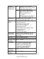
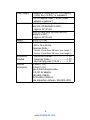
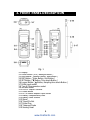
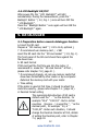
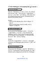
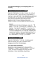
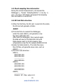
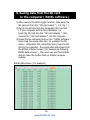
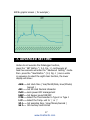
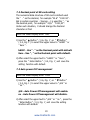
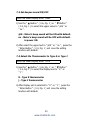
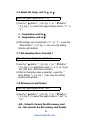
USER MANUAL
Hot Wire Anemometer
ATE-1034
www.tmatlantic.com
TABLE OF CONTENTS
1. FEATURES................................................................................ 1
2. SPECIFICATIONS...................................................................... 2
3. FRONT PANEL DESCRIPTION..................................................... 6
3-1 Display............................................................................... 6
3-2 Power Button ( ESC, Backlight Button )................................. 6
3-3 Hold Button ( Function Button, Next Button )........................ 6
3-4 REC Button ( Enter Button, Unit Button )............................. 6
3-5 SET Button ( ˑ Button, Time check Button )......................... 6
3-6 Logger Button ( ˏ Button, Sampling time check Button )....... 6
3-7 Probe input socket.............................................................. 6
3-8 Type K/J Probe Input Socket............................................... 6
3-9 SD card socket.................................................................... 6
3-10 RS-232 Output Terminal.................................................... 6
3-11 Reset Button..................................................................... 6
3-12 DC 9V Power Adapter Input Socket..................................... 6
3-13 Battery Compartment/Cover............................................... 6
3-14 Battery Cover's Screws...................................................... 6
3-15 Stand............................................................................... 6
3-16 Tripod Fix Nut................................................................... 6
3-17 Probe Plug........................................................................ 6
3-18 Telescope Probe............................................................... 6
3-19 Sensing Head................................................................... 6
4. MEASURING PROCEDURE.......................................................... 7
4-1 Function selection .............................................................. 7
4-2 Air velocity/Temp. measurement.......................................... 8
4-3 Type K/J thermometer ....................................................... 10
4-4 Data Hold...........................................................................11
4-5 Data Record ( Max./ Min. reading ).......................................11
4-6 LCD Backlight ON/OFF.........................................................12
5. DATALOGGER...........................................................................12
5-1 Preparation before execute datalogger function.....................12
5-2 Auto Datalogger ( Set sampling time ʁ 1 second )...............13
5-3 Manual Datalogger ( Set sampling time = 0 second )............ 14
5-4 Check time information........................................................14
5-5 Check sampling time information..........................................15
5-6 SD Card Data structure........................................................15
6. Saving data from the SD card to the computer............................ 16
7. ADVANCED SETTING.................................................................17
7-1 Set clock time ( Year/Month/Date, Hour/Minute/ Second )......18
7-2 Decimal point of SD card setting...........................................19
7-3 Auto power OFF management .............................................19
7-4 Set beep Sound ON/OFF..................................................... 20
7-5 Select the thermometer type to Type K or Type J.................. 20
7-6 Select the temperature unit to ɗ or ə ...............................21
7-7 Set sampling time ..............................................................21
7-8 SD memory card format...................................................... 21
8. POWER SUPPLY from DC ADAPTER............................................ 22
9. BATTERY REPLACEMENT...........................................................22
10. SYSTEM RESET.......................................................................23
11. RS232 PC serial interface.........................................................23
12. Optional Type K Temp. probe.................................................. 25
www.tmatlantic.com
1. FEATURES
* Combination of hot wire and standard thermistor,
deliver rapid and precise measurements even at low
air velocity value.
* Slim probe, ideal for grilles & diffusers.
* Air velocity : m/s, Ft/min, Km/h, Knot, Mile/h,
* Air temperature ( ɗ, ə )
* Air Temp. used thermistor sensor, fast response time.
* Type K, Type J thermocouple thermometer.
* Real time SD memory card Datalogger, it Built-in Clock
and Calendar, real time data recorder , sampling time set
from 1 second to 3600 seconds.
* Manual datalogger is available ( set the sampling
time to 0 ), during execute the manual datalogger
function, it can set the different position ( location ) No.
( position 1 to position 99 ).
* Innovation and easy operation, computer is not need
to setup extra software, after execute datalogger, just
take away the SD card from the meter and plug in the
SD card into the computer, it can down load the all the
measured value with the time information (
year/month/date/ hour/minute/second ) to the Excel
directly, then user can make the further data or graphic
analysis by themselves.
* SD card capacity : 1 GB to 16 GB.
* LCD with green light backlight, easy reading.
* Can default auto power off or manual power off.
* Data hold, record max. and min. reading.
* Microcomputer circuit, high accuracy.
* Power by UM3/AA ( 1.5 V ) x 6 batteries or DC 9V adapter.
* RS232/USB PC COMPUTER interface.
* Separate probe, easy for operation of different
measurement environment.
1
www.tmatlantic.com
* Applications : Environmental testing, Air conveyors,
Flow hoods, Clean rooms, Air velocity, Air balancing,
Fans/motors/blowers, Furnace velocity, Refrigerated case,
Paint spray booths.
2. SPECIFICATIONS
2-1 General Specifications
Circuit
Custom one-chip of microprocessor LSI
circuit.
Display
LCD size : 52 mm x 38 mm
LCD with green backlight ( ON/OFF ).
Measurement Air velocity:
Unit
m/s (meters per second)
Km/h ( kilometers per hour )
Ft/min ( FPM, feet per minute )
Knots ( nautical miles per hour )
Mile/h ( mph, miles per hour )
Air temperature:
ɗ, ə
Type K/ Type J thermometer.
ɗ, ə
Sensor
Air velocity & Air flow :
Structure
Tiny glass bead thermistor.
Air temperature :
Thermistor.
Type K, Type J thermometer :
Type K/J thermocouple probe.
* Probes are optional.
2
www.tmatlantic.com
Datalogger
Auto
Sampling Time
Setting range
Manual
1 second to 3600 seconds
@ Sampling time can set to 1 second,
but memory data may loss.
Push the data logger button
once will save data one time.
@ Set the sampling time to
0 second.
@ Manual mode, can also select the
1 to 99 position ( Location ) no.
Memory Card
Advanced
setting
SD memory card. 1 GB to 16 GB.
* It recommend use memory card ʀ 4 GB.
* Set clock time ( Year/Month/Date,
Hour/Minute/ Second )
* Decimal point of SD card setting
* Auto power OFF management
* Set beep Sound ON/OFF
* Set thermometer type to Type K or Type J
* Set temperature unit to ɗ or ə
* Set sampling time
* SD memory card Format
Temperature
Compensation
Automatic temp. compensation for the
Anemometer function and the type K/J
thermometer.
Data Hold
Freeze the display reading.
Memory Recall Maximum & Minimum value.
Sampling Time Approx. 1 second.
of Display
Data Output
RS 232/USB PC computer interface.
* Connect the optional RS232 cable
UPCB-02 will get the RS232 plug.
* Connect the optional USB cable
USB-01 will get the USB plug.
Operating
0 to 50 ɗ.
Temperature
Operating
Less than 85% R.H.
Humidity
3
www.tmatlantic.com
Power Supply
Power Current
Weight
Dimension
* AAlkaline or heavy duty DC 1.5 V battery
( UM3, AA ) x 6 PCs, or equivalent.
* ADC 9V adapter input. ( AC/DC power
adapter is optional ).
Normal operation ( w/o SD card save
data and LCD Backlight is OFF) :
Approx. DC 30 mA.
When SD card save the data and LCD
Backlight is OFF) :
Approx. DC 50 mA.
515 g/ 1.13 LB.
Main instrument :
203 x 76 x 38 mm
Telescope Probe :
Round, 12 mm Dia x 280 mm ( min. length ).
Round, 12 mm Dia x 940 mm ( max. length ).
Accessories
Included
Optional
Accessories
* Instruction manual........................1 PC
* Telescope Probe........................... 1 PC
* Hard carrying case ( CA-06 )..........1 PC
SD Card ( 1 G )
SD Card ( 2 G )
Type K thermocouple probe.
AC to DC 9V adapter.
USB cable, USB-01.
RS232 cable, UPCB-02.
Data Acquisition software, SW-U801-WIN.
4
www.tmatlantic.com
2-2 Electrical Specifications (23± 5 ɗ)
Air velocity
Measurement Range
Resolution Accuracy
m/s
0.2 to 5.0 m/s
0.01 m/s
± ( 5% + a )
5.1 to 25.0 m/s
0.1 m/s
reading
Km/h
0.70 to 18.00 km/h 0.01 Km/h
18.0 to 72.0 km/h 0.1 Km/h
or
Mile/h
0.50 to 11.20 mph 0.01 mph
± ( 1% + a )
( mph )
11.2 to 44.7 mph 0.1 mph
full scale
Knot
0.40 to 9.70 knot 0.01 Knot
9.7 to 38.8 knot
0.1 Knot
Ft/min
40-3940 ft/min
1 Ft/min
@ a = 0.1 m/s, 0.3 km/h, 0.2 mile/h, 0.2 knot, 20 ft/min
Note:
m/s - meters per second
km/h - kilometers per hour
ft/min - feet per minute
knot - nautical miles per hour
mile/h - miles per hour
(international knot)
Air temperature
Measuring Range
Resolution
Accuracy
0 ɗ to 50 ɗ/32 ə to 122 ə
0.1 ɗ/0.1 ə
± 0.8 ɗ/1.5 ə
Type K/J thermometer
Sensor
Type
Type K
Resolution
Range
Accuracy
0.1 ɗ
-50.0 to 1300.0 ɗ
± ( 0.4 % + 0.5 ɗ )
-50.1 to -100.0 ɗ
± ( 0.4 % + 1 ɗ )
0.1 ə
-58.0 to 2372.0 ə
± ( 0.4 % + 1 ə )
-58.1 to -148.0 ə
± ( 0.4 % + 1.8 ə )
Type J
0.1 ɗ
-50.0 to 1100.0 ɗ
± ( 0.4 % + 0.5 ɗ )
-50.1 to -100.0 ɗ
± ( 0.4 % + 1 ɗ )
0.1 ə
-58.0 to 2012.0 ə
± ( 0.4 % + 1 ə )
-58.1 to -148.0 ə
± ( 0.4 % + 1.8 ə )
@ Above specification tests under the environment RF Field Strength
less than 3 V/M & frequency less than 30 MHz only.
5
www.tmatlantic.com
3. FRONT PANEL DESCRIPTION
Fig. 1
3-1 Display
3-2 Power Button ( ESC, Backlight Button )
3-3 Hold Button ( Function Button, Next Button )
3-4 REC Button ( Enter Button, Unit Button )
3-5 SET Button ( ˑ Button, Time check Button )
3-6 Logger Button ( ˏ Button, Sampling time check Button )
3-7 Probe input socket
3-8 Type K/J thermometer socket
3-9 SD card socket
3-10 RS-232 Output Terminal
3-11 Reset Button
3-12 DC 9V Power Adapter Input Socket
3-13 Battery Compartment/Cover
3-14 Battery Cover Screws
3-15 Stand
3-16 Tripod Fix Nut
3-17 Probe Plug
3-18 Telescope Probe
3-19 Sensing Head
6
www.tmatlantic.com
4. MEASURING PROCEDURE
4-1 Function selection
1) Turn on the meter by pressing the " Power Button "
( 3-2, Fig. 1 ) momentarily.
* Pressing the " Power Button " ( 3-2, Fig. 1 )
continuously and > 2 seconds again will turn off the
meter.
2) The meter can select 2 kind function as :
a. Air velocity/Temp.
d. Type K/J Thermometer
Pressing the " Function Button " ( 3-3, Fig. 1 )
continuously ( not release the button ), the Display
will show the following text in sequence :
Air
tP
Air velocity/Temp. measurement
Type K/J Thermometer measurement
Until the Display show the desired mode ( Function ),
just release the " Function Button " ( 3-3, Fig. 1 ), the
meter will execute this function with default.
7
www.tmatlantic.com
4-2 Air velocity/Temp. measurement
1) Important information of using the Telescope Probe
* When the probe is not used, the " Sensor cover "
should slide to the up position.
When the probe is not used, the
" Sensor cover " should slide to the
up position.
Fig. 2
Probe Handle
* When begin to use the probe,
a. Slide the sensor cover to the down position, let the
air velocity sensor to contact the air, refer Fig. 3.
b. Extent the telescope probe to the convenient length
,refer to Fig. 3
air velocity sensor
( do not touch by
fingers or tools )
Fig. 3
" Sensor cover "
slide to the low
position when
make the
measurement
Probe Handle
8
www.tmatlantic.com
* Do not use the fingers or any tools to touch the air
velocity sensor, otherwise the meter may happen
the permanent damage without warranty.
* Direction of the sensor head :
There is a mark on the top of the " Sensor Head ",
When make the measurement, then this mark should
against the measured wind, refer Fig. 4.
When sensor head face against the measurement air,
then the upper display will show the air velocity value.
The lower display will show the temperature value.
Direction mark should face
the measured wind.
sensor head ( side view )
Fig. 4
Probe Handle
2) Function select to " Air velocity/Temp. " measurement.
3) Plug the " Probe Plug " ( 3-17, Fig. 1 ) into the " Probe
Input Socket " ( 3-7, Fig. 1 ).
Power on the meter by pressing the " Power Button "
( 3-2, Fig. 1 ) once,
4) Hold the " Telescope Probe " ( 3-18, Fig. 1 ) by hand and
let the " Sensing Head " ( 3-19, Fig. 1 ) face against the
measuring air flow source, then the Display ( 3-1, Fig. 1 )
will show air velocity directly. At the same time, the
lower Display will show the air temperature value.
9
www.tmatlantic.com
Measuring Consideration :
The mark on the sensor head indicates the
direction that " need to face against the air
flow.
Change the Air velocity unit
Air velocity unit are :
m/s, FPM ( Ft/min ), Km/h, Knots, mph ( Mile/h )
If intend to change the Air velocity unit, press the
Unit Button " ( 3-4 ) continuously, the unit will
change from m/s to Km/h, mph, Knot, FPM in
sequence, until the desired unit is present on the
Display release the " Unit Button ", the
select unit will save into the memory with default.
Change the temperature unit ( ɗ, ə )
The meter Temp. display unit is defaulted to " ɗ ".
If intend to let the meter's temperature unit default
to " ə " , then please refer chapter 7-6 ( page 21 ).
4-3 Type K/J thermometer
1) Function select to " Type K/J thermometer "
2) Plug the Thermocouple Temp. Probe ( Type K Temp.
probe pr Type J Temp. probe, optional ) into " Type
K/J Probe Input Socket " ( 3-8, Fig. 1 )
The Display will show the measuring value that
sensing from the Temp. probe.
3) If the Display show the indicator " K ", it is ready
for Type K thermometer.
If the Display show the indicator " J ", it is ready
for Type J thermometer.
10
www.tmatlantic.com
Remark :
The meter is defaulted to " Type K thermometer ".
If intend to select the " Type J thermometer with
default , please refer chapter 7-5 ( page 20 ).
4-4 Data Hold
During the measurement, press the " Hold Button " ( 3-3,
Fig. 1 ) once will hold the measured value & the LCD will
display a " HOLD " symbol.
Press the " Hold Button " once again will release the data
hold function.
4-5 Data Record ( Max., Min. reading )
1) The data record function records the maximum and
minimum readings. Press the " REC Button " ( 3-4, Fig.
1 ) once to start the Data Record function and there
will be a " REC " symbol on the display.
2) With the " REC " symbol on the display :
a) Press the " REC Button " ( 3-4, Fig. 1 ) once, the
" REC MAX " symbol along with the maximum value
will appear on the display.
If intend to delete the maximum value, just press
the " Hold Button " ( 3-3, Fig. 1 ) once, then the
display will show the " REC " symbol only & execute
the memory function continuously.
b) Press the " REC Button " ( 3-4, Fig. 1 ) again, the
" REC MIN " symbol along with the minimum value
will appear on the display.
If intend to delete the minimum value, just press
the " Hold Button " ( 3-3, Fig. 1 ) once, then
the display will show the " REC " symbol only &
execute the memory function continuously.
c) To exit the memory record function, just press the
" REC " button for 2 seconds at least. The display will
revert to the current reading.
11
www.tmatlantic.com
4-6 LCD Backlight ON/OFF
After power ON, the " LCD Backlight " will light
automatically. During the measurement, press the "
Backlight Button " ( 3-2, Fig. 1 ) once will turn OFF the
" LCD Backlight ".
Press the " Backlight Button " once again will turn ON the
" LCD Backlight " again.
5. DATALOGGER
5-1 Preparation before execute datalogger function
a. Insert the SD card
Prepare a " SD memory card " ( 1 G to 16 G, optional ),
7 It recommend use memory card ʀ 4 GB.
insert the SD card into the " SD card socket " ( 3-9, Fig. 1).
The front panel of the SD card should face against the
the down case.
b. SD card Format
If SD card just the first time use into the meter, it
recommend to make the " SD card Format " at first. ,
please refer chapter 7-8 ( page 21 ).
* It recommend strongly, do not use memory cards that
have been formatted by other meter or by a computer.
Reformat the memory card with your meter.
c. Time setting
If the meter is used at first time, it should to adjust the
clock time exactly, please refer chapter 7-1 ( page 18 ).
d. Decimal format setting
The numerical data structure of SD card is
default used the " . " as the decimal, for
example "20.6" "1000.53" . But in certain
countries ( Europe ...) is used the " , " as the
decimal point, for example " 20, 6 "
"1000,53". Under such situation, it should
change the Decimal character at first, details
of setting the Decimal point, refer to Chapter
7-2, page 19.
12
www.tmatlantic.com
5-2 Auto Datalogger ( Set sampling time ʁ 1 second )
a. Start the datalogger
Press the " REC Button ( 3-4, Fig. 1 ) once , the LCD will
show the text " REC ", then press the " Logger Button " (
3-6, Fig. 1 ), the " REC " will flashing, at the same time
the measuring data along the time information will be
saved into the memory circuit.
Remark :
!+ How to set the sampling time, refer to Chapter 7-7,
page 21.
!+ How to set the beeper sound is enable, refer to
Chapter 7-4, page 20.
b. Pause the datalogger
During execute the Datalogger function , if press the
" Logger Button " ( 3-6, Fig. 1 ) once will pause the
Datalogger function ( stop to save the measuring data
into the memory circuit temporally ). In the same time
the text of " REC " will stop flashing.
Remark :
If press the " Logger Button " ( 3-6, Fig. 1 ) once again
will execute the Datalogger again, the text of " REC " will
flashing .
c. Finish the Datalogger
During pause the Datalogger, press the " REC Button " (
3-4, Fig. 1) continuously at least two seconds, the " REC "
indication will be disappeared and finish the Datalogger.
13
www.tmatlantic.com
5-3 Manual Datalogger ( Set sampling time = 0
second )
a. Set sampling time is to 0 second
Press the " REC Button ( 3-4, Fig. 1 ) once , the LCD will
show the text " REC ", then press the " Logger Button " (
3-6, Fig. 1 ) once, the " REC " will flashing once and Beeper
will sound once, at the same time the measuring data
along the time information will be saved into the
memory circuit. The lower Display will show the
Position ( Location ) no. and saved into the SD card too.
Remark :
During execute the Manual Datalogger, press the " ˑ
Button " ( 3-5, Fig, 1 ) the lower no. ( position no. ) will
flashing. It can use the " ˏ Button " ( 3-6, Fig. 1) or "
ˑ Button " ( 3-5, Fig. 1 ) to set the measuring position (
1 to 99, for example room 1 to room 99 ) to identify the
measurement location , the lower Display will show P x (
x = 1 to 99 ). After the position no. is selected, t press
the " Enter Button " ( 3-4, Fig. 1 ) to confirm.
b. Finish the Datalogger
Press the " REC Button " ( 3-4, Fig. 1) continuously at
least two seconds, the " REC " indication will be
disappeared and finish the Datalogger.
5-4 Check time information
During the normal measurement ( not execute the
Datalogger ), If press " Time check Button " ( 3-5, Fig. 1
) once , the lower LCD display will present the time
information of Year, Month/Date, Hour/Minute
14
www.tmatlantic.com
5-5 Check sampling time information
During the normal measurement ( not execute the
Datalogger ), If press " Sampling Button " ( 3-6, Fig. 1 )
once , the lower LCD display will present the Sampling
time information in second unit.
5-6 SD Card Data structure
1) When the first time, the SD card is used into the meter,
the SD card will generate a folder :
AHA01
2) If the first time to execute the Datalogger,
under the route AHA01\, will generate a new
file name AHA01001.XLS.
After exist the Datalogger, then execute again,
the data will save to the AHA01001.XLS until
Data column reach to 30,000 columns, then
will generate a new file, for example AHA01002.XLS
3) Under the folder AHA01\, if the total files more
than 99 files, will generate anew route, such as
AHA02\ ........
4) The file's route structure :
AHA01\
AHA01001.XLS
AHA01002.XLS
.....................
AHA01099.XLS
AHA02\
AHA02001.XLS
AHA02002.XLS
.....................
AHA02099.XLS
AHAXX\
.....................
Remark : XX - Max. value is 10.
15
www.tmatlantic.com
6. Saving data from the SD card
to the computer ( EXCEL software )
1) After execute the Data Logger function, take away the
SD card out from the " SD card socket " ( 3-9, Fig. 1 ).
2) Plug in the SD card into the Computer's SD card slot
( if your computer build in this installation ) or
insert the SD card into the " SD card adapter ". then
connect the " SD card adapter " into the computer.
3) Power ON the computer and run the " EXCEL software ".
Down load the saving data file ( for example the file
name : AHA01001.XLS, AHA01002.XLS ) from the SD
card to the computer. The saving data will present into
the EXCEL software screen ( for example as following
EXCEL data screens ) , then user can use those EXCEL
data to make the further Data or Graphic analysis
usefully.
EXCEL data screen ( for example )
16
www.tmatlantic.com
EXCEL graphic screen ( for example )
7. ADVANCED SETTING
Under do not execute the Datalogger function,
press the " SET Button " ( 3-5, Fig. 1 ) continuously at
least two seconds will enter the " Advanced Setting " mode.
then press the " Next Button " (3-3, Fig. 1 ) once a while
in sequence to select the eight main function, the lower
display will show :
dAtE......Set clock time ( Year/Month/Date, Hour/Minute/
Second )
dEC....... Set SD card Decimal character
PoFF......Auto power OFF management
bEEP..... Set beeper sound ON/OFF
tYPE......Select the Thermometer to Type K or Type J
t-CF.......Select the Temp. unit to ɗ or ə
SP-t...... Set sampling time ( Hour/Minute/Second )
Sd F..... SD memory card Format
17
www.tmatlantic.com
Remark :
During execute the " Advanced Setting " function,
if press " Esc Button " ( 3-2, Fig. 1 ) once will exit
the " Advanced Setting " function, the LCD will
return to normal screen.
7-1 Set clock time ( Year/Month/Date,
Hour/Minute/ Second )
When the lower display show " dAtE "
1) Press the " Enter Button " ( 3-4, Fig. 1 ) once,
Use the " ˏ Button " ( 3-6, Fig. 1 ) or " ˑ Button "
( 3-5, Fig. 1 ) to adjust the value ( Setting start from
Year value ). After the desired value is set, press the
" Enter Button " ( 3-4, Fig. 1 ) once will going to
next value adjustment ( for example, first setting
value is Year then next to adjust Month, Date, Hour,
Minute, Second value ).
2) After set all the time value ( Year, Month, Date, Hour,
Minute, Second ),
the screen will jump to " Decimal point of SD crad setting "
screen ( Chapter 7-2 ).
Remark :
After the time value is setting, the internal clock will
run precisely even Power off if the battery is under
normal condition ( No low battery power ).
18
www.tmatlantic.com
7-2 Decimal point of SD card setting
The numerical data structure of SD card is default used
the " . " as the decimal, for example "20.6" "1000.53" .
But in certain countries ( Europe ...) is used the " , " as
the decimal point, for example " 20,6 " "1000,53".
Under such situation, it should change the Decimal
character at first.
When the lower display show " dEC "
1) Use the " ˏ Button " ( 3-6, Fig. 1 ) or " ˑ Button "
( 3-5, Fig. 1 ) to select the upper value to " bASIC " or
" Euro ".
bASIC - Use " . " as the Decimal point with default.
Euro - Use " , " as the Decimal point with default.
2) After select the upper text to " bASIC " or " Euro ",
press the " Enter Button " ( 3-4, Fig. 1 ) will save the
setting function with default.
7-3 Auto power OFF management
When the lower display show " PoFF "
1) Use the " ˏ Button " ( 3-6, Fig. 1 ) or " ˑ Button "
( 3-5, Fig. 1 ) to select the upper value to " yES " or
" no ".
yES - Auto Power Off management will enable.
no - Auto Power Off management will disable.
2) After select the upper text to " yES " or " no ", press the
" Enter Button " ( 3-4, Fig. 1 ) will save the setting
function with default.
19
www.tmatlantic.com
7-4 Set beeper sound ON/OFF
When the lower display show " bEEP "
1) Use the " ˏ Button " ( 3-6, Fig. 1 ) or " ˑ Button "
( 3-5, Fig. 1 ) to select the upper value to " yES " or
" no ".
yES - Meter's beep sound will be ON with default.
no - Meter's beep sound will be OFF with default.
is power ON.
2) After select the upper text to " yES " or " no ", press the
" Enter Button " ( 3-4, Fig. 1 ) will save the setting
function with default.
7-5 Select the Thermometer to Type K or Type J
When the lower display show " tYPE "
1) Use the " ˏ Button " ( 3-6, Fig. 1 ) or " ˑ Button "
( 3-5, Fig. 1 ) to select the Display unit to " K " or
" J ".
K - Type K thermometer
j - Type J thermometer
2) After Display unit is selected to " K " or " J ", press the
" Enter Button " ( 3-4, Fig. 1 ) will save the setting
function with default.
20
www.tmatlantic.com
7-6 Select the Temp. unit to ɗ or ə
When the lower display show " t-CF "
1) Use the " ˏ Button " ( 3-6, Fig. 1 ) or " ˑ Button "
( 3-5, Fig. 1 ) to select the upper Display text to " C " or
" F ".
C - Temperature unit is ɗ
F - Temperature unit is ə
2) After Display unit is selected to " C " or " F ", press the
" Enter Button " ( 3-4, Fig. 1 ) will save the setting
function with default.
7-7 Set sampling time ( SecondS )
When the lower display show " SP-t "
1) Use the " ˏ Button " ( 3-6, Fig. 1 ) or " ˑ Button "
( 3-5, Fig. 1 ) to adjust the value ( 1, 2, 5, 10, 30,60,
120, 300, 600, 1800,3600 seconds ).
2) After teh Sampling value is selected, press the "
Enter Button " ( 3-4, Fig. 1 ) will save the setting
function with default.
7-8 SD memory card Format
When the lower display show " Sd F "
1) Use the " ˏ Button " ( 3-6, Fig. 1 ) or " ˑ Button "
( 3-5, Fig. 1 ) to select the upper value to " yES " or
" no ".
yES - Intend to format the SD memory card
no - Not execute the SD memory card format
21
www.tmatlantic.com
2) If select the upper to " yES ", press the " Enter Button
" ( 3-4, Fig. 1 ) once again, the Display will show text
" yES Enter " to confirm again, if make sure to do the
SD memory card format, then press " Enter Button "
once will format the SD memory clear all the existing
data that already saving into the SD card.
8. POWER SUPPLY from DC
ADAPTER
The meter also can supply the power supply from the
DC 9V Power Adapter ( optional ). Insert the plug of
Power Adapter into " DC 9V Power Adapter Input Socket
" ( 3-12, Fig. 1 ). The meter will permanent power ON
when use the DC ADAPTER power supply ( The power
Button function is disable ).
9. BATTERY REPLACEMENT
1) When the left corner of LCD display show "
", it
is necessary to replace the battery. However, in-spec.
measurement may still be made for several hours after
low battery indicator appears before the instrument
become inaccurate.
2) Loose the screws of the " Battery Cover " ( 3-14, Fig. 1 )
and take away the " Battery Cover " from the instrument
and remove the battery.
3) Replace with DC 1.5 V battery ( UM3, AA,
Alkaline/heavy duty ) x 6 PCs, and reinstate the cover.
4) Make sure the battery cover is secured after changing
the battery.
22
www.tmatlantic.com
10. SYSTEM RESET
If the meter happen the troubles such as :
CPU system is hold ( for example, the key button can
not be operated... ).
Then make the system RESET will fix the problem.
The system RESET procedures will be either following
method :
During the power on, use a pin to press the " Reset
Button " ( 3-11, Fig. 1 ) once a while will reset the
circuit system.
11. RS232 PC SERIAL INTERFACE
The instrument has RS232 PC serial interface via a 3.5
mm terminal ( 3-10, Fig. 1 ).
The data output is a 16 digit stream which can be
utilized for user's specific application.
A RS232 lead with the following connection will be
required to link the instrument with the PC serial port.
23
www.tmatlantic.com
Meter
PC
(9W 'D" Connector)
Center Pin..........................Pin 4
(3.5 mm jack plug)
Ground/shield.......................Pin 2
2.2 K
resistor
Pin 5
The 16 digits data stream will be displayed in the
following format :
D15 D14 D13 D12 D11 D10 D9 D8 D7 D6 D5 D4 D3 D2 D1 D0
Each digit indicates the following status :
D0
End Word
D1 & D8 Display reading, D1 = LSD, D8 = MSD
For example :
If the display reading is 1234, then D8 to
D1 is : 00001234
D9
Decimal Point(DP), position from right to the
left
0 = No DP, 1= 1 DP, 2 = 2 DP, 3 = 3 DP
D10
Polarity
0 = Positive 1 = Negative
D11 & D12 Annunciator for Display
ɗ = 01
Knot = 09
mile/h = 12
ə = 02
Km/h = 10
m/s = 08
ft/min = 11
D13
When send the upper display data = 1
When send the lower display data = 2
D14
4
D15
Start Word
24
www.tmatlantic.com
RS232 FORMAT : 9600, N, 8, 1
Baud rate
Parity
Data bit no.
Stop bit
9600
No parity
8 Data bits
1 Stop bit
12. Optional Type K Temp. probe
(Type K) TP-01
Thermocouple
Probe
(Type K), TP-02A
Thermocouple
Probe
(Type K), TP-03
Surface Probe
(Type K), TP-04
* Max. short-tern operating
Temperature: 300 ɗ (572 ə).
* It is an ultra fast response
naked-bead thermocouple
suitable for many general purpose
application.
* Measure Range: -50 ɗ to 900 ɗ,
-58 ə to 1650 ə.
* Dimension:12cm tube, 3.2mm Dia.
* Measure Range: -50 ɗ to 1100 ɗ,
-58 ə to 2012 ə.
* Dimension: 13.6cm tube, 8mm Dia.
* Measure Range: -50 ɗ to 400 ɗ,
-58 ə to 752 ə.
* Size :
Temp. sensing head - 15 mm Dia.
Probe length - 120 mm.
25
www.tmatlantic.com