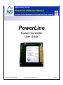
1
High Country Tek, Inc.
PowerLine User Guide
Power-Line (PLD) User Manual
Electronic Control Solutions for the Global Fluid Power Industry
,
PowerLine
System Controller
User Guide
Part No:- 021-00155 RevD7
PowerLine System Controller User Guide
Page | 1
PowerLine User Guide
Welcome to the High Country Tek Inc. ( HCT ) PowerLine system controller user guide, and thank you for
selecting this HCT controller to use in your application
The following information is designed to allow you to connect, set-up and optimize the PowerLine module.
If you have used HCT products before, you will recognize some of the instructions and settings. For those of you
that are new to HCT, please read the directions with care and be sure that if you have any questions regarding
this industry unique controller, then please contact us using one of the numbers given on the back page of this
manual.
We value our customers, their experience and abilities and ask that if you would like to see any additions,
subtractions or find any errors in this publication, that you contact HCT’s customer service so that we can
correct the information and make sure that our programming community is using the latest information.
If you require urgent support, more information or would like specific programming areas clarified, you can
contact us on the customer support number at 1 530 265 3236 or E-mail us through our website at
www.hctcontrols.com, giving details of your issue and how we can contact you.
Introduction:
This manual is designed to provide information needed for the installation and use of the Power Line Valve
Controller. Its intended user is qualified trained service personnel that understand the hazards involved in an
electromechanical environment. It is recommended that this manual be read in its entirety before installation is
begun with particular attention paid to caution and safety information.
Cautions:
Changing setup values and limits under computer control while the machine is operating may cause sudden
machine movement, which may lead to possible injury or death. It is strongly recommended that any moving
parts are disabled prior to any alignment procedure whenever possible. In any case, caution should be
exercised during any procedure and work should be completed only by qualified trained personnel.
Warranty Information:
High Country Tek Inc. Guarantees this product to be free of defects in materials and workmanship for a period
of one year extending from the date the unit was shipped from the factory. Within this time frame, High Country
Tek will provide evaluation of warranted items free of charge. Warranty repair or replacement will be at the
factory’s discretion. If necessary, contact the factory for return authorization by phone (530) 265-3236, Fax
(530) 265-3275, E-Mail [email protected] or by writing our service department at, High Country Tek,
Service Dept., 208 Gold Flat Court, Nevada City, CA 95959. To help us serve you better, please have the units
full Model / Part Number and Serial Number available when contacting the factory for any reason. Do not return
products to the factory without prior authorization and a RMA number attached.
Part No:- 021-00155 RevD7
PowerLine System Controller User Guide
Page | 2
PowerLine User Guide
Manual Index:
Introduction: ........................................................................................................................... 2
Cautions: ............................................................................................................................................................ 2
Warranty Information: ........................................................................................................................................ 2
Manual Index: ......................................................................................................................... 3
Product Application Guidelines: ........................................................................................... 4
PowerLine flexible configurations: ....................................................................................... 5
Module Familiarity: ................................................................................................................. 6
Module Compatibility and Valve Settings:............................................................................ 8
Module Connections: ........................................................................................................... 11
PowerLine Dimensional Information: ................................................................................. 13
Electrical Specification Overview: ...................................................................................... 14
Opto 3000: USB serial Interface .......................................................................................... 15
Software PowerLine Installation ......................................................................................... 16
System Requirements ...................................................................................................................................... 16
Using The PowerLine application ....................................................................................... 17
File ( Memory Options ): ...................................................................................................... 17
Control Logic: ....................................................................................................................... 18
Manual PWM% ................................................................................................................................................ 19
Horse Power Limiter & Anti-Stall Mode ............................................................................................................ 20
Horse Power Limiter & Anti Stall Mode with Reverse ...................................................................................... 21
Horse Power Limiter & Anti Stall with Max Command ..................................................................................... 22
Proportional Valve Driver Mode ....................................................................................................................... 23
Setup: .................................................................................................................................... 24
Help: ...................................................................................................................................... 32
Exit the program (GUI) ..................................................................................................................................... 32
Troubleshooting: .................................................................................................................. 33
Application Connection Examples:..................................................................................... 36
Ordering Guide: .................................................................................................................... 38
Default Files and Set-up tips: .............................................................................................. 39
Valve Driver Settings: .......................................................................................................... 40
Dual Coil Valve Driver ...................................................................................................................................... 40
Command Input: .............................................................................................................................................. 40
Process Setup:................................................................................................................................................. 41
Coil Setup: ....................................................................................................................................................... 41
Single Coil Valve Driver ................................................................................................................................... 42
Command Input Command Input: .................................................................................................................... 42
Process Setup:................................................................................................................................................. 42
Coil Setup: ....................................................................................................................................................... 42
Horse Power Limiter & Anti-Stall Mode .............................................................................. 43
Dual Coil Driver ................................................................................................................................................ 43
Pulse Input: ...................................................................................................................................................... 43
Command Input: .............................................................................................................................................. 43
Process Setup:................................................................................................................................................. 44
Coil Setup: ....................................................................................................................................................... 44
Anti-Stall with Max Command: ......................................................................................................................... 44
Need More Information ? ................................................................................................................................. 45
Part No:- 021-00155 RevD7
PowerLine System Controller User Guide
Page | 3
PowerLine User Guide
Product Application Guidelines:
ALWAYS do the following:
•
•
•
•
•
•
•
•
•
•
•
•
•
•
•
•
Take a few minutes to FULLY read THESE information / data sheets BEFORE starting.
Keep High Voltage AC cables separate from Low Voltage DC signal and supply cables.
Make sure the unit supply voltage is the same as the coils on the valve being driven !
Ensure that you are aware of the adjustments and consequences on the electronics and hydraulics.
Make sure you have the correct tools to do the intended job ( i.e. Opto unit, P.C., software ) e.t.c.
‘Isolate’ this unit from all other equipment BEFORE any form of welding takes place.
Check ALL connections to and from this unit to ensure NO short or OPEN circuits.
Check the units supply voltage is CORRECT, ‘ ELECTRICALLY CLEAN ’ and STABLE.
Operate the units within specified operating temperature for best & reliable performance.
Ensure that any unused wires / terminals are terminated safely and not shorted together.
Use screened cables wherever possible for best immunity to external interference.
Use cables that are capable of carrying the required voltage and current for your products and application.
Isolate the controller if ANY form of battery charging or battery boosting takes place on the vehicle.
Ensure ALL valve connectors are wired correctly, secure, locked and connected to correct coils.
Observe the set-up procedures in this manual for best operational results.
Follow and abide by local and country health & safety standards – protect yourself and others !
NEVER do the following:
•
•
•
•
•
•
•
•
•
Arc Weld or Charge Batteries with this driver unit connected as damage can occur.
Attempt to use this unit if you are unsure of electrical OR hydraulic connections or expected operation.
Attempt to use this unit in Areas where other AC or DC coils HAVE NOT been fully suppressed.
Use a power supply that is not rated for the correct required O/P current under full load.
Allow wires TO or FROM the unit to short circuit ( to each other or chassis/cabinet e.t.c. ).
Attempt to use this unit in areas of intense RF without adequate screening measures.
Disconnect or connect wires to or from this unit unless it isolated from the power supply.
Use this unit in temperatures that exceed those specified as operation may be effected.
Start this unit without ensuring ALL work areas are clear of personnel !
Software Safety:
The software has been carefully written to give the user the maximum system configuration flexibility while being
transparent in operation and easy to use, even for novice system builders and operators.
To ensure safety when using the software and to prevent accidental connection to another module that is not a
PowerLine, rules have been written into the software to ensure correct operation at all times:
When the PC running the GUI is first connected to a powered PowerLine, and before any data exchange can be
allowed, a ‘Handshake’ takes place that confirms the internal software ( BIOS ) is compatible, the serial number and
the PowerLine part number. The GUI then checks to ensure that its own revision is compatible with the module
software and only then allows the PC and the module to communicate and share data.
If at any point during the process above an error or mis-match is detected, the GUI software will NOT allow
communications and will inform the user of the problem via a clear message in the ‘Status’ window.
Part No:- 021-00155 RevD7
PowerLine System Controller User Guide
Page | 4
PowerLine User Guide
PowerLine flexible configurations:
The PowerLine module is ideally suited for today’s hydraulic OEM, distributor or system builder. With both
mechanical and electrical robustness paramount in the design priority, Windows™ compatible easy to use setup software and full CE compliance means this one product can through , the many configurations and features
available, be used across multiple platforms, markets and applications.
This units cost effectiveness will become quickly apparent through the reduction in inventory costs and stocking
needs as well as in the reduced costly engineering time taken usually associated with the design to delivery
cycle.
The PowerLine has five (5) basic configurable modes of operation available within the one module.:
1) Manual control of the output current through the graphical user interface.
This mode is typically used during system start-up and commissioning. Used to prove control and
direction of motion as well as correct hoses and fittings are leak free.
2) Horse Power Limiter & Anti-Stall – automotive style prime mover protection.
Used to protect an engine from stalling by progressively reducing the hydraulic load either by valve or
pump control, effectively de-coupling the load from the motor. The active nature of this mode allows the
machine to find the optimized work rate and still support healthy engine RPM.
2a) Horse Power Limiter & Anti-Stall with Reverse –
Ideal for system such as auto-feed wood chippers or any applications that need a reverse feature if the
engine starts to stall because of a forced load.
3) Horse Power Limiter & Anti-Stall with Max Command Used to protect an engine from stalling by progressively reducing the hydraulic load either by valve or
pump control, effectively de-coupling the load from the motor. Extra Features are provided to allow the
user to vary the maximum command signal with a pot or joystick during Anti-Stall operations.
4) Valve Driver – Direct open loop control of single or dual coil valves or pump controls.
The last mode provides a quick, easy method of controlling single or dual coil valves or pump strokers.
This unit will drive all the major OEM products and can be set easily to interface with a simple joystick or
work from an external command signal of either voltage or current.
Part No:- 021-00155 RevD7
PowerLine System Controller User Guide
Page | 5
PowerLine User Guide
Module Familiarity:
Wiring:
Use 16 AWG wire for power and coil wiring. Use of shrouded coil connectors is always recommended.
Shielded cables are preferred for the pulse and command inputs as these are typically low level, analog signals.
This will minimize potential cross talk between cables that are bundled or in a cable harness.
Additional noise protection can be obtained by shielding the coil and power cables. The shields should be
grounded only at the unit end of the cable.
Long cable runs with any other cables, especially high voltage or those carrying switching type signals in close
proximity of each other should be avoided.
Take extra care to isolate any cable that are connected to high voltage AC electric motors, variable frequency or
variable voltage drives.
Protecting the unit’s pulse input from external noise is very important and can save a lot of time in
troubleshooting.
NOTE:
The unit MUST be installed with an in-line fuse in the positive supply cable. Use only an AGC-5 fuse.
Locate the fuse as close to the power supply as possible to provide protection to both the wiring and
the unit. Failure to use a fuse invalidates the warranty, can be dangerous to the system and also the
PowerLine unit.
Part No:- 021-00155 RevD7
PowerLine System Controller User Guide
Page | 6
PowerLine User Guide
INPUT ERROR LED blink code descriptions:
LED
Condition
OFF
Input or feedback signal operation is normal
Blinking
Error detected or loss of feedback
Solution
Check command or feedback signal for
connection, signal level and polarity and
correct as required
Power LED blink code description:
LED
OFF
ON
Blinking
Condition
Power Supply below 9VDC
Power supply between 9VDC and 30VDC
Power supply above 30VDC
Solution
Increase power supply to >9VDC
NO action – normal operation
Reduce power supply to <30VDC
PWM% A and PWM% B Output LED blink code description:
LED
OFF
GREEN
RED
ORANGE
Flash RED 2Hz
Flash GREEN 1Hz
Condition
NO output or not in use
Respective output fully ON
Respective output fully OFF
Respective output in transition or under control
Respective output SHORT circuited, module turns OFF PWM
output
Respective output OPEN circuited turns OFF PWM output
Solution
Check power supply or module fuse
Turn OFF power and clear short circuit,
turn power back on
Turn OFF power and re-connect open
circuit turn power back on
SHORT and OPEN CIRCUIT ERROR DETECTION:
If power is applied to the controller while connected to an existing short circuit, the module will not detect this or
show an error led and will output PWM current equivalent to the Imax setting.
The module ( which should be protected by an AGC5 fuse as reccomended ) will be regulating and will not
damage itself in this mode, but the issue can only be diagnosed by using the GUI and observing that the current
is changing but the PWM% is only moving to a max of ~5% of max output.
If power is applied to the controller while connected to an existing open circuit, the module will not detect this or
show an error led until the PWM output is commanded to control current.
Part No:- 021-00155 RevD7
PowerLine System Controller User Guide
Page | 7
PowerLine User Guide
Module Compatibility and Valve Settings:
Valve Type
PSL/V – (Size 2)
PSL/V – (Size 2)
PSL/V(F) – (Sizes 3 & 5)
PSL/V(F) – (Sizes 3 & 5)
EM 21 D(S)E
EM 21 D(S)E
EMP 21 S
EMP 21 S
EMP 21 V
EMP 21 V
EMP 21 S10
EMP 21 S10
EMP 21 V10
EMP 21 V10
EMP 31 S
EMP 31 S
EMP 31 V
EMP 31 V
EMP 31 S10
EMP 31 S10
EMP 31 V10
EMP 31 V10
EMP 41 S
EMP 41 S
EMP 41 V
EMP 41 V
PMV
PMV
PDM, PDV
PDM, PDV
PM(Z)
PM(Z)
SE - (Sizes 2 & 3)
SE - (Sizes 2 & 3)
SEH - (Sizes 2 & 3)
SEH - (Sizes 2 & 3)
SWS 2
SWS 2
V30D "V" Controller
Coil
Voltage
(V)
12
24
12
24
12
24
12
24
12
24
12
24
12
24
12
24
12
24
12
24
12
24
12
24
12
24
12
24
12
24
12
24
12
24
12
24
12
24
24
IMin
(mA)
IMax
(mA)
~450 mA
~225 mA
~620 mA
~310 mA
~50 mA
~25 mA
~550 mA
~240 mA
~500 mA
~200 mA
~40 mA
~20 mA
~400 mA
~200 mA
~240 mA
~120 mA
~400 mA
~200 mA
~150 mA
~75 mA
~400 mA
~200 mA
~100 mA
~200 mA
~100 mA
~200 mA
~200 mA
~100 mA
~190 mA
~110 mA
~200 mA
~100 mA
~380 mA
~190 mA
~250 mA
~130 mA
~400 mA
~260 mA
~250 mA
~1,160 mA
~580 mA
~1,260 mA
~630 mA
~1,200 mA
~630 mA
~1,100 mA
~480 mA
~1,000 mA
~500 mA
~1,300 mA
~650 mA
~1,380 mA
~690 mA
~1,200 mA
~600 mA
~1,000 mA
~500 mA
~1,200 mA
~600 mA
~1,560 mA
~780 mA
~870 mA
~1,750 mA
~870 mA
~1,750 mA
~1,260 mA
~630 mA
~1,200 mA
~680 mA
~1,260 mA
~630 mA
~1,900 mA
~950 mA
~1,260 mA
~630 mA
~1,350 mA
~880 mA
~750 mA
Dither
Frequency
(Hz)
40 - 70 Hz (55)
40 - 70 Hz (55)
40 - 70 Hz (55)
40 - 70 Hz (55)
50 - 150 Hz
50 - 150 Hz
50 - 150 Hz
50 - 150 Hz
50 - 150 Hz
50 - 150 Hz
50 - 150 Hz
50 - 150 Hz
50 - 150 Hz
50 - 150 Hz
50 - 150 Hz
50 - 150 Hz
50 - 150 Hz
50 - 150 Hz
50 - 150 Hz
50 - 150 Hz
50 - 150 Hz
50 - 150 Hz
50 - 150 Hz
50 - 150 Hz
50 - 150 Hz
50 - 150 Hz
60 - 150 Hz
60 - 150 Hz
50 - 150 Hz
50 - 150 Hz
50 - 150 Hz
50 - 150 Hz
60 - 150 Hz
60 - 150 Hz
60 - 150 Hz
60 - 150 Hz
50 - 150 Hz
50 - 150 Hz
80 - 100 Hz
Dither
Amplitude
(%)
20 - 35%
20 - 35%
20 - 35%
20 - 35%
20 - 40%
20 - 40%
20 - 40%
20 - 40%
20 - 40%
20 - 40%
20 - 40%
20 - 40%
20 - 40%
20 - 40%
20 - 40%
20 - 40%
20 - 40%
20 - 40%
20 - 40%
20 - 40%
20 - 40%
20 - 40%
20 - 40%
20 - 40%
20 - 40%
20 - 40%
20 - 40%
20 - 40%
20 - 40%
20 - 40%
20 - 40%
20 - 40%
20 - 40%
20 - 40%
20 - 40%
20 - 40%
20 - 40%
20 - 40%
20 - 40%
Note: Final optimized settings are valve size and system/application dependent. Consult valve manufacturer for full details
as required.
Part No:- 021-00155 RevD7
PowerLine System Controller User Guide
Page | 8
PowerLine User Guide
Valve Type
Coil
Voltage
(V)
IMin
(mA)
IMax
(mA)
Dither
Frequency
(Hz)
Dither
Amplitude
(%)
Note: Final optimized settings are valve size and system/application dependent. Consult valve manufacturer for full details
as required.
Valve Type
70 size / Proportional Coil
70 size / Proportional Coil
EHPR / Proportional coil
EHPR / Proportional coil
Coil
Voltage
(V)
12
24
12
24
IMin
(mA)
IMax
(mA)
~<100
~<100
~<100
~<100
1500
750
~1100 -1200
~550 - 600
Dither
Frequency
(Hz)
~200
~200
~200
~200
Dither
Amplitude
(%)
50 – 100
50 – 100
50 – 100
50 – 100
Note: Final optimized settings are valve size and system/application dependent. Consult valve manufacturer for full details
as required.
Valve Type
F5C
VP014VP014VP014RP01
9A – Pump stroker coil
4DP01 – single OR dual coil
4DP01 – single OR dual coil
4DP02 – single OR dual coil
4DP02 – single OR dual coil
3DP03 – single OR dual coil
3DP03 – single OR dual coil
3DP06 – single OR dual coil
3DP06 – single OR dual coil
Coil
Voltage (V)
IMin
(mA)
IMax
(mA)
12
24
12
24
24
24
12
24
12
24
12
24
12
24
~200
~250-500
~100-300
~200
~150
~250
~250
~250
~250
~400
~200
~400
~200
~220-250
~800
~2700
~1500
~800
~350
~2300-2500
~1100-1300
~2200-2700
~1250-1500
~1500-1700
~550-750
~1500-1700
~550-750
Dither
Frequency
(Hz)
70
140
250
250
140
250
250
250
100
100
250
140
250
140
Dither
Amplitude
(%)
50 - 100
50 – 100
50 – 100
50 – 100
50 – 100
50 – 100
50 – 100
50 – 100
50 – 100
50 – 100
50 – 100
50 – 100
50 – 100
50 - 100
Note: Final optimized settings are valve size and system/application dependent. Consult valve manufacturer for full details
as required.
Part No:- 021-00155 RevD7
PowerLine System Controller User Guide
Page | 9
PowerLine User Guide
Valve Type
DAAL, DBAL, DLDA, DMDA, DNDA,
DNDC, DTCA, DTDA, DWDA, FMDA,
FMDB, PRDL, PRDM, PRDN, PRDP,
RBAN, RBAP
DAAL, DBAL, DLDA, DMDA, DNDA,
DNDC, DTCA, DTDA, DWDA, FMDA,
FMDB, PRDL, PRDM, PRDN, PRDP,
RBAN, RBAP
Coil
Voltage
Imin (mA)
12
Imax (mA)
1150mA
24
590
Dither
Frequency
Dither
Amplitude
100 –
250Hz
dependant on
valve size
100 –
250Hz
dependant on
valve size
Note: Final optimized settings are valve size and system/application dependent. Consult valve manufacturer for full details
as required.
Valve Type
HPV – 02 – E1
HPV – 02 – E1
Coil
Voltage
12
24
Imin (mA)
Imax (mA)
~440 – 460
~215 – 235
~810 - 1200
~410 – 600
Dither
Frequency
100 Hz
100 Hz
Dither
Amplitude
Note: Final optimized settings are valve size and system/application dependent. Consult valve manufacturer for full details
as required.
Valve Type
PRM2-04
PRM2-04
PRM2-06
PRM2-06
PVRM1-063/S
PP2P-06
PRM6-10
PRM6-10
PVRM3-10
SR4P-B2
SR4P-B2
Coil
Voltage
12
24
12
24
12
12
12
24
12
12
24
Imin (mA)
Imax (mA)
~600-700
~250-270
~700-850
~270-310
~250-310
~300-330
~600-700
~300-400
~250-290
~150-210
~150-210
~1700
~800
~2500
~1000
~1000-1200
~1000-1100
~1900
~1100
~1500
~1000
~750
Dither
Frequency
90
60
90
60
100
150
90
60
100
160
160
Dither
Amplitude
0-30
0-30
0-30
0-30
0-30
0-30
-
Note: Final optimized settings are valve size and system/application dependent. Consult valve manufacturer for full details
as required.
Part No:- 021-00155 RevD7
PowerLine System Controller User Guide
Page | 10
PowerLine User Guide
Module Connections:
+Power ( connector terminal 1 ):
This is the main + Voltage power supply input for the module. The PowerLine controller will accept 9 to 30VDC.
NOTE:
Make sure the unit has an in-line fuse fitted to protect the system, the module and the warranty.
+Coil A ( Connector terminal 2 ):
This terminal should be connected to the ‘A’ coils positive (+) connection. It is switched ON or OFF to decide
which if any coil will be driven. These terminals should not be connected to +Power.
+Coil B ( Connector terminal 3 ):
This terminal should be connected to the ‘B’ coils positive (+) connection. It is switched ON or OFF to decide
which if any coil will be driven. These terminals should not be connected to +Power.
-Coil A ( Connector terminal 4 ):
Both -Coil A and -Coil B are internally connected together on the card and should be connected to the negative
coil leads. These are used to sense coil current, control the internal feedback circuit that maintains and
regulates current to the coils to recover from heating effects and should never be grounded.
-Coil B ( Connector terminal 5 ):
Both -Coil A and -Coil B are internally connected together on the card and should be connected to the negative
coil leads. These are used to sense coil current, control the internal feedback circuit that maintains and
regulates current to the coils to recover from heating effects and should never be grounded.
Power Com ( Connector terminal 6 ):
This is the main 0 Volts ( GND ) power supply connection for the module.
Sig Com ( Connector terminal 7 ):
This terminal is internally tied to Power Common ( Power Com ) on the card. To provide the best possible
noise resistance Sig Com should be used as the only ground for the pulse and command sensors.
Command In ( Connector terminal 8 ):
This is the analog command input for the controller. The Graphical User Interface (GUI ) allows the user
through software to choose from several selectable ranges including 0 to +5-Volts, 0 to +10-Volts and +4-20mA.
There is also the facility that lets the user choose Uni or Bi-directional operation by setting the inputs so their
respective mid points become the zero crossover point ( i.e. 0-5V becomes 0 – 2.5– 5) with 2.5V representing
NO drive to the valve coils.
This input has an impedance of 100 KOhms when ‘Voltage Mode’ is selected and is internally pulled low to allow
for error detection and avoid spurious signals if not used.
Pulse In ( Connector terminal 9 ):
This is a programmable range input that accepts pulses above up to 30KHz. Pulses must cross the midpoint of
the range selected to be detected and may exceed the range without damage to the unit if less than +/- 30-Volts
Peak. Selectable ranges include –1 to +1V, 0 to 1.25V, 0 to 2.5V, 0 to 5V and 0 to 10V. A GUI software switch
is provided to allow the user to activate an internal 10KOhm pull down resistor on this input. Activation of the
pull down resistor is intended to provide loading for inductive, sourcing or open emitter sensors.
Part No:- 021-00155 RevD7
PowerLine System Controller User Guide
Page | 11
PowerLine User Guide
Module Connections Cont.
NOTE:
Sinking or open collector sensors may require an external pull up resistor.
Pot Ref Out ( Connector terminal 10 ):
Pot Ref Out provides +5VDC through a 1KΩ current limit resistor ( 5mA max ) and is typically used for local
connection to a 10K potentiometer or Joystick.
NOTE:
This output should not be used as a sensor power supply as it will not supply sufficient current.
Enable In ( Connector terminal 11 ):
This is a sinking switch input. Activation is achieved by pulling the input high to either +5-Volts or to the module
+power supply connection.
This input nominal impedance is 10 KOhms.
NOTE:
This input is internally pulled low to prevent a floating input when deactivated or not in use.
Direction ( Connector terminal 12 ):
This is a sinking switch input that may be used to activate ‘Coil B’ remotely.
This innovative feature allows the user to have full resolution of the command source by choosing when to
select the coil ‘B’ drive output rather than offsetting the command input to mid-point.
Activation is achieved by pulling the input high to either +5-Volts or to the modules +power supply connection.
This input nominal impedance is 10 KOhms.
NOTE:
This input is internally pulled low to prevent a floating input when deactivated or not in use.
Part No:- 021-00155 RevD7
PowerLine System Controller User Guide
Page | 12
PowerLine User Guide
PowerLine Dimensional Information:
Housing Type:-
High Country Tek unique ‘encapsulated’ block.
Housing Material:-
None, solid, flameproof epoxy resin block.
Housing Color:-
Black / dark Grey.
Surface Finish:-
Gloss
Housing Thickness:-
12mm ( main module ) 25mm incl. Connectors.
Unit size:-
See above size detail drawings.
Unit Weight:-
Approx.... 400 grams ( including Encapsulation material )
Wire entry:-
Via heavy duty screw type connector.
Encapsulation:-
Flame Resistant, Black , Two Part Epoxy Resin.
Mounting:-
Via through holed ( 3 ) suitable for No. 8 ( 5mm ) screw .
Temperature range:-
- 40 to +85 degrees Centigrade ( operational )
Part No:- 021-00155 RevD7
PowerLine System Controller User Guide
Page | 13
PowerLine User Guide
Electrical Specification Overview:
1
2
3
4
5
6
7
8
9
10
11
12
13
14
15
16
17
18
19
20
21
22
23
24
25
26
27
28
29
30
31
-
Board Style:
Connector Type:
Input Supply Voltage:
Input supply current:
Input supply protection:
User Reference Voltage:
User Reference Voltage current:
Command Input types:
DCV Command input value range:
DC Current Command Input Range
Pulse Command input value range:
Pulse command voltage range:
Enable input value range:
Enable input impedance:
Parameter Adjustments:
Coil ‘A’ current setting range:
Coil ‘B’ current setting range:
Coil ‘A’ & ‘B’ Protection:
Ramp ‘A’ max setting range:
Ramp ‘B’ max setting range:
Dither frequency (Hz ) range:
Dither amplitude max:
Process ‘P’ term scale factor range:
Process ‘I’ term scale factor range:
Industry Compliance:
Environmental:
IP rating:
NEMA rating:
Humidity:
Storage Temp range:
Operating temp range:
Part No:- 021-00155 RevD7
High Country Tek unique size and mounting.
12 way heavy duty screw terminal.
9 – 30VDC ( absolute maximums )
~400mA quiescent + valve currents
User supplied in-line fuse ( AGC5 )
+5VDC ( +/- 10% ) – short circuit protected.
~5mA ( Absolute maximum ) current limited.
DC Voltage and pulse
0 – 5VDC or 0 – 10VDC
4 – 20mA ( 100 Ohm resistor load )
0 – 30 KHz
±0 – ±30V absolute max.
0 – 5V or +module supply
10 KOhm
All through graphical user interface software.
~0 – 3000mA ( with current feedback circuit )
~0 – 3000mA ( with current feedback circuit )
Open and short circuit detect circuit.
~0 – 10 seconds up and down
~0 – 10 seconds up and down
~0 – 250Hz
~0 – 5V Pk-Pk
0-7
0-7
Designed to meet latest CE certification standards
Totally encapsulated unit for mechanical protection.
IP68 ( Module only - derate for connectors as required )
6P ( Module only - derate for connectors as required )
95 – 100% Non condensing
-60 to +90 Deg C ( Max )
-40 to + 85 Deg C ( max )
PowerLine System Controller User Guide
Page | 14
PowerLine User Guide
Opto 3000: USB serial Interface
The Opto 3000 is the newest way to interface with any PC running
Windows™ XP® Professional and Vista Business or Ultimate, to
program or observe operation of the PowerLine module.
The unit is USB compatible comes with all the cables needed to start
work immediately.
The Opto 3000 gets power from the PC USB port so the user should
take care to select a port that can support 5VDC output ( beware of
USB expansion hubs with maximum load limitations ). The unit has
TX and RX LED’s available to allow the user to observe activity on
the communications cable.
The kit has all the parts you will need to connect and/or externally
power the interface as required.
To begin using the Opto 3000, Locate a free USB communications
port on your computer . Connect and secure one end of the supplied
USB cable into the port of the computer, the other end into the Opto3000 connector.
Important NOTE:
The optical interface head that mechanically connects to the PowerLine module has a ‘RED mark’ on
one end - This mark should be facing towards the “PWR OK” indicator.
Part No:- 021-00155 RevD7
PowerLine System Controller User Guide
Page | 15
PowerLine User Guide
Software PowerLine Installation
You are now ready to install and start the PowerLine program by Inserting the software CD and running the
‘setup.exe’ program – follow the on-screen instructions.
After installation, the program will be found in the Start menu group called “HCT Products“.
Once the software has been installed, restart your computer.
Before you find and run the PowerLine software program, ensure all
mechanical and electrical connections are secure between the PC and the
Opto 3000 and that the PowerLine module is connected to a correct power
supply and turned ON.
When the software is started, and depending on your PC software set-up,
the first thing it will do is to find the connected Opto 3000 and may display
the screen on the left while it is doing this operation.
After a few seconds, the available Communications ( COM ) ports will show
up as Green. Select the port being used for communications. If you are
correct, the screen , left will disappear and the main program screen will
replace it – congratulations, you are now communicating with the PowerLine
controller.
In most instances, when using the Opto 3000, the PC will detect the unit as
soon as it is connected, and automatically select a port and start the
PowerLine user interface.
System Requirements
Windows XP Professional, Vista Business or Ultimate
256MB RAM or greater
Serial Port RS232 or USB Adapter
Opto 3000 and USB cable
•
The PowerLine Graphical User Interface part
number is:- P/N: 023-00206
•
Ensure you have the latest version of software for
this module by contacting our customer service
and support personel if required.
•
Run Setup.exe from the install CD.
•
Follow the on-screen instructions as you are
prompted.
Figure 1, Main Screen
Part No:- 021-00155 RevD7
PowerLine System Controller User Guide
Page | 16
PowerLine User Guide
Using The PowerLine application
File ( Memory Options ):
Selection from Menu -> Save Temporary Memory to Permanent Memory
NOTE: It is strongly reccomended that the user cycles power to the PowerLine module after saving any
program changes to ensure that the setting alterations take place and any old setting data is erased by
the controller.
The unit stores all user programmable
settings both in temporary and permanent
memory. The unit reads the values from
permanent memory in the PowerLine “EEprom” into temporary memory only at
power up or when the “Restore Temporary
Memory from Permanent Memory” menu
item is selected. The temporary memory
values, “settings”, are used in operation.
The PowerLine control program allows
altering the values in temporary memory,
which immediately (and temporarily)
affects the unit’s operation. The control
program also allows saving the parameters
in temporary memory into the unit’s
permanent memory by selecting “Save
Temporary to Permanent Memory”.
Changes that are not saved will be lost
when power is turned off or if the Restore Temporary Memory from Permanent Memory is selected.
Caution: The unit does not function while settings are being saved. Use of this selection
temporarily prevents the unit from working in the system. Do not select this option while the machine
is operating.
Selection from Menu -> Save Temporary Memory to Permanent Memory & File
The control program can save and restore all unit settings to or from a file. The temporary and permanent
memory values in the unit are made to be identical during operations to avoid confusion about what was saved
or restored. When the Save Temporary Memory to Permanent Memory & a File is selected, the temporary
settings are saved to permanent memory. Next, the user is prompted for a file name and location to save the
new settings to. This file can be used to program other units identically or act as a backup while adjusting the
unit. This feature also allows a replacement unit to be set up identically to the original without having to
manually determine the required values for a particular installation.
Caution: Use of this selection temporarily prevents the unit from working in the system.
Do not select this option while the machine is operating.
Part No:- 021-00155 RevD7
PowerLine System Controller User Guide
Page | 17
PowerLine User Guide
Selection from Menu -> Restore Temporary Memory from Permanent Memory
Restores settings stored in permanent memory to temporary (operational) memory.
Caution: Use of this selection temporarily prevents the unit from working in the system.
Do not select this option while the machine is operating.
Selection from Menu -> Restore Temporary & Permanent
Memory from a File
When this selection is made, the user is prompted for a file
name and location from which to retrieve settings. The
restored values are placed in temporary and permanent
memory.
Caution: Use of this selection temporarily prevents the
unit from working in the system.
Do not select this option while the machine is operating.
Control Logic:
This drop down menu allows the user to
select what control mode the controller will
operate in:
1. Manual PWM control ( Set-up )
2. Anti-Stall (Reverse option available)
3. Anti-Stall with Max Command
4. Valve Control ( Single or dual coil )
IMPORTANT NOTE – DUAL COIL OPERATION:
The output of either ‘A’ or ‘B’ output will go from the respective ‘I Min’ setting to ZERO (0mA ) when crossing
through command mid-point. The valve outputs do NOT jump from one I Min to the other.
Part No:- 021-00155 RevD7
PowerLine System Controller User Guide
Page | 18
PowerLine User Guide
Manual PWM%
Selection from Menu -> Control Logic-> Manual PWM% Mode
This feature allows the user to manually
control the output current to coils ‘A’ and ‘B’
( PWM% ) by the using the ‘Virtual
Potentiometer’ shown colored as ‘Yellow’
on the screen to the left.
This option can be used for coil and system
setup and is ideal for troubleshooting.
NOTE for information:
The “Current = LOS Current” status message is always displayed ( not seen on this screen shot )
on the GUI when using or in this controller mode.
IMPORTANT NOTE – DUAL COIL OPERATION:
The output of either ‘A’ or ‘B’ output will go from the respective ‘I Min’ setting to ZERO (0mA ) when crossing
through command mid-point. The valve outputs do NOT jump from one I Min to the other.
Part No:- 021-00155 RevD7
PowerLine System Controller User Guide
Page | 19
PowerLine User Guide
Horse Power Limiter & Anti-Stall Mode
NOTE: It is strongly reccomended that the user cycles power to the PowerLine module after saving any
program changes to ensure that the setting alterations take place and any old setting data is erased by
the controller.
Selection from Menu -> Control Logic -> Anti-Stall – Single Coil Operation
The PowerLine will adjust its outputs as a
function of the RPM of a device. Anti-stall,
or load limiting, progressively de-couples
the load as RPM decreases to avoid
stalling the prime mover ( electric motor or
engine ). This method is typically used in
situations where the throttle of the engine
is controlled by the operator and the load
changes independently such as a
propulsion circuit. The Anti-Stall action is
used to prevent a sudden increase in load
from causing the engine to stall before the
operator has a chance to increase the
throttle or decrease the load, or to
automatically adjust the load without
operator intervention.
When the prime mover RPM is less than
the STOP RPM setting, the PowerLine
outputs MIN current and the load will be completely removed. When the RPM is more than the SLOW RPM, the
PowerLine will output Max current. Setting the MAX current value too high can delay the start of load decoupling until an RPM less than the SLOW RPM set point has been reached.
The separation between the SLOW RPM and
STOP RPM determines how aggressively the
load is reduced. This algorithm can be used as
a continuously variable transmission controller
when connected to a variable displacement
pump or motor. Ramps are provided to tune the
response time (PID constants do not affect this
process). This algorithm can cause oscillations if
the ramp times are too short in some systems.
Ramps are easy to tune as there is only one
number to adjust per ramp and there are only
four independently tunable ramps. The ramps
are simply increased from zero until the
oscillation (if any) stops or the desired
smoothness is achieved. Because the ramp
settings are independent, the rate of reducing
the load can be set differently than the rate for
re-applying the load.
Part No:- 021-00155 RevD7
Output
Current[A]
Single Coil Operation
MAX
MIN
Stop RPM
Slow RPM
Figure 2 Coil Current vs. Demand in
Anti Stall Mode
PowerLine System Controller User Guide
Page | 20
PowerLine User Guide
Horse Power Limiter & Anti Stall Mode with Reverse
Selection from Menu -> Control Logic -> Anti-Stall Mode with Reverse
The PowerLine controller has a new useful
function that combines Anti-stall with a
reverse feature.
This feature will allow the user to set up the
anti-stall as normal with ‘SLOW’ and
‘STOP’ limits, with the difference being that
if the monitored RPM reaches the ‘STOP’
limit, the controller will turn the PWM% A
output fully off, then turn the PWM% B on
to offer a reverse feature.
The ramps used for the PWM% A and
PWM% B are set in the process setup
window as shown here.
‘SLOW’
Setpoint
Normal RPM level
RPM
‘STOP’
Setpoint
Ramp set
by rate of
RPM
decline
PWM% A
Output A to
ZERO
PWM% A – Full ON
Ramp
PWM% A
UP setting
Auto Reverse
Time
PWM% B
100mS
Dwell
Ramp
PWM% B
UP setting
Ramp
PWM% B
DOWN
setting
PWM% B – Full OFF
100mS
Dwell
IMPORTANT NOTE: Reverse feature ON/OFF setting
The reverse feature is turned OFF by setting the ‘Auto Reverse Time’ to 0 (ZERO) seconds.
The auto reverse feature is turned ON if there is any time entered in the ‘Auto Reverse Time’ box.
The minimum reverse time is 0.5 seconds while the max is ~85 seconds.
Part No:- 021-00155 RevD7
PowerLine System Controller User Guide
Page | 21
PowerLine User Guide
Horse Power Limiter & Anti Stall with Max Command
Selection from Menu -> Control Logic-> Anti Stall w Max Command
Anti Stall w Max Command is the same as
Anti-Stall except for the addition of the
COMMAND input that adjusts the MAX
current. The effect of the COMMAND
input is exactly the same as changing the
MAX current setting, with the adjustment
range of the analog input being the MIN to
MAX current values set by the Opto 3000.
See the graph in figure 7. Anti Stall w
Max Command mode can be used to give
the operator a joystick controlled load
horsepower, or load speed, adjustment in
addition to the automatic load reduction
process that prevents stalling the engine.
Figure 3 Coil Current V’s.
Command Voltages in Anti
Stall w Max Command Mode
Output
Current[B]
Output
Current[A]
MAX
Slow RPM
deadband
Stop RPM
MIN
Min
Center
Command Input
MAX
IMPORTANT NOTE – DUAL COIL OPERATION:
The output of either ‘A’ or ‘B’ output will go from the respective ‘I Min’ setting to ZERO (0mA ) when
crossing through command mid-point. The valve outputs do NOT jump from one I Min to the other.
Part No:- 021-00155 RevD7
PowerLine System Controller User Guide
Page | 22
PowerLine User Guide
Proportional Valve Driver Mode
Selection from Menu -> Control Logic-> Valve Control Mode
This mode allows you to adjust the coil
current based on the command input. This
method is typically used in situations
where the output current needs to be
controlled directly using a joystick.
The valve driver can operate in either dual
coil or single coil mode. Figure A shows
the characteristics of the valve driver mode
in dual coil mode which is ideal for
directional valve control or for pump swash
control.
Figure 8 shows single coil characteristic
which is ideal for flow or pressure control
operation.
Figure A Coil Current vs. Command Voltages in
Valve Driver Mode with dual coils
Figure B Coil Current vs. Command Voltages in
Valve Driver Mode with single coil
IMPORTANT NOTE – DUAL COIL OPERATION:
The output of either ‘A’ or ‘B’ output will go from the respective ‘I Min’ setting to ZERO (0mA ) when
crossing through command mid-point. The valve outputs do NOT jump from one I Min to the other.
Part No:- 021-00155 RevD7
PowerLine System Controller User Guide
Page | 23
PowerLine User Guide
Setup:
NOTE: It is strongly reccomended that the user cycles power to the PowerLine module after saving any
program changes to ensure that the setting alterations take place and any old setting data is erased by
the controller.
From this screen, the user has access to all of the setup sub-screens and drop downs that will enable the
configuration of the particular control logic mode that has been selected. The following pages describe the
setting available, their limits and what the effect is on the application being worked on.
NOTE:
Each Graphical User Interface screen may have grayed out settings or look different to the pictures
shown in this manual. This is due to the settings regarding the mode of operation and or other user
settings that may render them invalid or require them to be set to a mandatory set point.
Part No:- 021-00155 RevD7
PowerLine System Controller User Guide
Page | 24
PowerLine User Guide
Pulse Input Setup:
Selection from Menu-> Pulse Input Setup
Enable Pull Down Resistor
This check box is used to enable a 10k resistor from the
pulse input to ground for use on systems with open emitter
sensors.
Pulses Per Rev
Number of pulses per revolution
LOS Current (amps) – (Loss Of Signal Current)
The user can set the coil current to drive when a loss of
signal is detected.
Feedback Selection
Used to select a voltage range for the Pulse Input. Pulses
must cross the midpoint of the range selected to be
detected and may exceed the range without damage to the
unit if less than +/- 30-Volts.
RPM Range
Use to select the best range for the application. If more than one range works, select the lowest range that fits
your application.
Configuration Steps:
1.
2.
3.
4.
Enter the number of teeth or pulses per revolution (maximum 255)
Enter LOS (Loss Of Signal) Current
Select voltage range of the pulse input under Feedback Selection
Select a RPM range that best fits the application; choose the range with the highest “lower” RPM
value that will work.
Application Tips
Inductive Pickup - Use 1 to -1v for Feedback Selection value
Hall Effect Pickup- Use 0 – 5v, or 0 – 10v for Feedback Selection value
Part No:- 021-00155 RevD7
PowerLine System Controller User Guide
Page | 25
PowerLine User Guide
Command Input Setup:
Selection from Menu-> Command Input Setup
Command Error Detection
Enabled when checked disabled when
unchecked
Command Error = coils off
(active if command error detection = true)
activates when a command error is detected.
Coils turned off when checked, command
would go to “Command Error Default Volts”
when unchecked.
Command Range
Max - voltage to determine end of joystick travel
Center – Pot/joystick center point voltage
Min - voltage to determine end of joystick travel
Command Selection
0 to +5V or 0 to +10V or 4 to20mA options.
Command Error Default Volts - (active if command error detection = true) activates when a command error is
detected
If the unit senses a command error, this voltage value will be read by the card as the command voltage until the
error is corrected.
Command Error Limits - (active if command error detection = true)
The Command Error Limits feature will detect and report errors on the Command Input that exceed the user
defined set points.
NOTE:
If the command input value is outside the High and Low values entered here, the modules outputs will
be determined by the ‘Command Input Error’ settings
These settings are used when the Command Error Detection check box has been checked.
High - Command Input Error reported when command volts are greater than High.
Low - Command Input Error reported when command volts are less than Low.
Part No:- 021-00155 RevD7
PowerLine System Controller User Guide
Page | 26
PowerLine User Guide
Reference Error Limits - (active if command
error detection = true)
The Reference Error Limits feature will
detect and report errors on the Command
Reference Output of the module that
exceed the user defined set points. These
settings are used when the Command
Error Detection check box has been
checked.
High - Command Input Error reported when
reference volts are greater than High.
Low - Command Input Error reported when
reference volts are less than Low.
Auto Center
The voltage from the joystick is used during power up as the center command voltage, if it is within the Auto
Center limits set below. Check this box to enable auto center detect on power up.
Auto Center + - %
This setting is used to calculate how far a joystick can be out of the center set point in the command range. On
power up and sets limits for the Auto Center feature.
Deadband + - %
This setting installs a Deadband over the center portion of the command voltage range that is plus and minus
percent from Command center. When the Command Input Voltage is in this range, the coil outputs are
disabled.
Auto Calibrate:
This feature is used to gather information about
the input command signal. The command range,
command error limits and reference error limits
are set automatically. The user moves the input
command to minimum and maximum, pausing
momentarily then returns to center and presses
the Ok button. The values are then stored in the
controllers temporary memory. The user must
then select the “Save Temporary Memory to
Permanent
Memory”
menu
option
to
permanently save the calibration settings.
Part No:- 021-00155 RevD7
PowerLine System Controller User Guide
Page | 27
PowerLine User Guide
Advanced Settings:
Selection from Menu-> Advanced Settings
Process P and I Term Scale
These values allow for scaling the P and I term scale.
These values are only editable when the controller is in
RPM Regulation Mode. These values represent the
number of times to divide the effect of the P or I term by
two. Therefore, larger shift values will increasingly reduce
the effects of the P and I terms. The P shift value can be
from 0 to 7 (default = 5). The I shift value can be from 0 to
7 (default = 7). These setting should only be changed
when the use of process P, I and I time values were not
able to tune the process. (Refer to Tuning a PID controller)
NOTE:
These settings are pre-set for optimal response and are only available with the correct password please contact
HCT factory for further information.
Part No:- 021-00155 RevD7
PowerLine System Controller User Guide
Page | 28
PowerLine User Guide
Process Setup
Selection from Menu-> Process Setup
Ramp Up and Ramp Down
The units ( seconds ) are the time taken to
change from minimum output current
to
maximum output current, i.e. 0 – 100%.
Smaller changes within this window, will be a
ratio of this value. Commands to change coils
will be delayed by the ramping process.
In RPM regulation mode, the user can adjust
the speed of the change in the set point due to
changing command input. This does not affect
the speed of process regulation at a given set
point.
In load limiting and horsepower limiting mode
the user can adjust the speed of the change in
current due to changing command input.
Process P, I and I Time
These settings are used to tune the units response to input and output changes.
The P and I values have a range of 0 to 255 with default values of P = 10 and I = 2. The Process I time range is
4 to 512ms, default value 50ms. The default values typically produce a slow response time in the system. A
detailed explanation of these settings can be found in this user guide under the heading “PID -- The Basic
Technique for Feedback Control”.
The user can adjust the process control parameters here to tune the rate and aggressiveness of the speed
change relative to feedback as well as system under /overshoot for the speed regulation mode. Note that the
process setup settings, directly affect the output current value to the coil.
Minimum / Maximum RPM or Stop / Slow
The user can adjust the minimum and maximum RPM that is selected by the command input as it goes from its
minimum to maximum value in RPM Regulation mode. In Anti Stall mode, this is the Stop RPM and Slow RPM
set point.
Part No:- 021-00155 RevD7
PowerLine System Controller User Guide
Page | 29
PowerLine User Guide
More Current = More Speed
This software selectable feature allows the use
of reverse acting single coil valves. When this
box is unchecked, the PowerLine will apply
less current to get higher system speed. This
feature is only available if Disable Coil B is
selected. The current, when the coil is "off",
will be the MAX current in reverse acting
mode.
Enable Active High - (active when enable 'enable'
= true)
When this box is checked the PowerLine logic
is enabled when there is a high or > 5 VDC on
the enable input pin. When the check box is unchecked, the unit is enabled when there is a low or 0 volts on the
enable input pin. The unit is disabled when enable pin is not in the enabled state. This prevents driving the
outputs unless “More Current = More Speed” is unchecked. If unchecked, disabled causes max current. (Note:
The 'Enable Enable' check box must be checked for enable active to operate properly)
Enable the ‘Enable’ Input
When this box is checked the PowerLine will look at the ‘Enable In’ input to enable the controller. When this box
is unchecked, the PowerLine is always enabled.
Enable Direction
Use of the Direction input allows the user to use the full range ( resolution ) of the command input in each
direction when applicable.
This check box enables the (Direction) Coil B H In input to the controller. When selected, Coil B will be active
when the input is pulled high.
Ramp to 0 (zero) if Disabled
This check box determines the units behavior when the enable input is used and changes state. When this box
is checked, the ramp value and method in use with the selected algorithm is applied to turning off the output.
When this box is unchecked, the unit immediately turns off the output.
Anti-Stall - Current to 0 (Zero)
When the input RPM is less than the STOP RPM, the current will stay at MIN unless this box is checked, in
which case the current drops to zero from Imin without ramping. This option is only active in Anti-Stall mode.
Command Reverse Acting
This feature is available in “Anti Stall w Max Command” mode only. When checked, the Command Volts Min in
single coil operation demands 100 percent current and Command Volts Max demands 0 percent current.
Warning: It is dangerous to do this in dual coil operation, the Center Voltage will command 100 percent output.
Part No:- 021-00155 RevD7
PowerLine System Controller User Guide
Page | 30
PowerLine User Guide
Coil Setup
Selection from Menu-> Coil Setup
Minimum and Maximum current
The user can adjust the minimum and maximum
current on a per coil basis. The current output will
not be commanded outside of these ranges when
the coil is on. This feature is useful as it allows for
valve ‘deadband’ to be reduced, making the
system more responsive to small commands
around the zero position or point of a command
source ( i.e. Joystick e.t.c. ). The software has a
limit of zero (0) for minimum and a limit of
3000mA for maximum current.
EDC ( Electronic Displacement Control ) Type Coil
This soft switch changes the PWM frequency to a lower setting for use with low current coils to allow for better
current regulation. Check this box when using EDC coils
Note, Adjusting the max current above recommended OEM values may damage the coil and will reduce the
resolution of the process control
Disable Coil B
This software switch disables coil ‘B’ output. Check this box when using as a single coil valve or uni-direction
motor or open circuit pump.
NOTE:
Always make sure to uncheck the ‘Disable Coil B’ tick box when using a dual coil valve or bidirectional motor or closed circuit pump.
Dither Amplitude and frequency ( Hz )
Dither is commonly used to reduce the effects of valve hysteresis and stiction. These parameters can be
adjusted to suit the hydraulic product being controlled. Optimized values can typically be found in the
manufacturers datasheets.
IMPORTANT NOTE – DUAL COIL OPERATION:
The output of either ‘A’ or ‘B’ output will go from the respective ‘I Min’ setting to ZERO (0mA ) when
crossing through command mid-point. The valve outputs do NOT jump from one I Min to the other.
Part No:- 021-00155 RevD7
PowerLine System Controller User Guide
Page | 31
PowerLine User Guide
Help:
The ‘Help’ dropdown menu offers two
choices. The first opens a window that gives
the user information on the controller
Application and BIOS versions as well as
contact information for High Country Tek,
Inc.
The second option ‘View Help’ will open a
PDF file of this manual to allow the user
immediate access to information regarding
the controller, application, set-up and
troubleshooting.
Software Controls:
Exit the program (GUI)
Click the ‘Exit’ button on the man screen lower right hand corner.
NOTE:
Always use this method of terminating the PowerLine PC program. This cleanly exits the program and
also releases any communications port(s) in use for other applications.
Log Data
A data-logging feature is available to log the RPM, Coil Current and
RPM set point. This feature is useful for system troubleshooting and
remote debugging. The Log Data button is used to start the data
log process. The user is prompted for a file name and location after
the data has been collected. The data log contains 250 samples.
The timer period of the data log is less than a half of a minute on a
fast computer, to several minutes on a slow computer. The log file
is text and may be read into a spreadsheet and graphed.
Part No:- 021-00155 RevD7
PowerLine System Controller User Guide
Page | 32
PowerLine User Guide
Troubleshooting:
General Considerations
The ‘PWR OK’ LED must be steadily on, not flashing, for correct unit operation.
This LED will be off if the power supply is too low, and flashing if the power supply is too high. Intermittent low
power supply conditions also cause flashing. Large noise spikes on the power supply can cause the unit to
temporarily shut down due to over voltage.
The INPUT ERROR LED flashes if there is a fault with the COMMAND IN or PULSE IN inputs.
The PWM%A and B LED’s are on when their coil is driven. They range from red ( driving 0%) through green
(driving 100%). The LED’s flash red/off for shorted coils and green/off for open coils. +COIL leads shorted to
power or ground may be interpreted as either a short or open. -COIL leads shorted to power or ground will be
indicated as a short or open on whichever coil is driven first.
NOTE:
The unit WILL NOT drive coils after a short or open until the controllers power is cycled or disabled
then re-enabled by the ENABLE IN signal.
The trouble-shooting mode of Manual PWM% is available to drive the coils without reference to the pulse input.
This allows using a “Virtual Pot” on the computer to control the coil current. Valve selection for coil A or B is
obtained though the use of a “Soft Switch” next to the virtual pot. Manual PWM% applies 0 to 100% of the
power supply to the selected coil output and does not regulate current against power supply variations or coil
resistance changes.
Note: Care should be exercised when driving coils that are rated for lower voltages than the controllers
supply voltage ( i.e. 12V coil with 24V supply ). Over Driving a valve coil may/will damage the coil by
overheating.
The switch inputs have on screen indicators that toggle when that switch function is enabled.
Running graphs allows the viewing of several input and output signals. The PULSE IN voltage display is useful
to verify that the pulse sensor is providing the expected voltage swing. Note that this signal does not show
pulse shapes, but does indicate the range of amplitudes detected by the unit. These graphs can also be used to
aid in tuning the dynamics of the system regulation.
A LOG button allows saving the unit settings and sampling the inputs to the PC for later analysis. multiple logs
can be saved into the same file. Logs should always accompany trouble reports to the factory if possible.
Part No:- 021-00155 RevD7
PowerLine System Controller User Guide
Page | 33
PowerLine User Guide
On Site Testing:
If the set up procedure does not achieve the desired results, double check the wiring and perform the following
tests. Record the test results.
Tools required
A PC running Windows XP and an Opto 3000 are required for initial set-up, programming or observation of the
controllers operation through the RS232 port.
The PC can also be used for uploading the configured program to new PowerLine modules for series
production.
A battery operated multi-meter is always a good idea for measuring and confirming analog signals and an
oscilloscope would be useful for looking at fast moving or digital signals on the system as well as monitoring the
system power input for transients that could cause intermittent operation.
Check the power input:
The module will not function correctly unless the +POWER supply is at least 9 VDC when driving the coils.
If the supply voltage is below 9VDC, there is a risk of:
a) Module shutting down, b) Module continuously trying to reset or c) Low drive current to valves.
If the supply voltage is more than 30 VDC there is a risk of:
a) Blown in-line AGC5 fuse, b) Module internal damaged or c) Coil damage due to excessive drive voltage.
Check the control inputs:
Verify the control inputs are the correct polarity and are hooked up correctly to the correct module terminals by
monitoring their status with the PowerLine software or testing with a voltmeter or oscilloscope.
Ensure that any external control or command inputs have their respective 0V or GND connected to the modules
power supply 0V or GND terminal.
Verify the coil is not shorted or open:
Disconnect the wires going to the +COIL and -COIL terminals and measure the resistance between the wires.
Verify it is in the expected Ohmic range for the type and voltage of coil being driven. Verify that there is no
voltage between either wire and power or ground (indicating a short circuit to either power or ground).
NOTE:
If a +COIL or -COIL is short circuited or open circuited while being driven, the controller will shut
down its outputs until the user cycles controller power or disables then re-enables the module.
Check the card at full-on and full-off:
Do not try the full on test if the power supply is higher than the coil's rated voltage.
To test the card at full on, use the control software to go to Open Loop PWM mode and set the PWM to 100%.
Full-ON - Measure the voltage across the +COIL and -COIL and from +POWER to POWER COM. The voltage
difference should be no more than approx. one (1) volt if the card is operating correctly.
Full-OFF - To check the card at full off, Enter the GUI and go to the ‘Manual PWM’ screen and set the PWM to
0% in open loop mode. Measure across the +COIL to -COIL voltage which should be zero volts.
Part No:- 021-00155 RevD7
PowerLine System Controller User Guide
Page | 34
PowerLine User Guide
Valve not being driven to maximum:
If the card passes the "full on test" above, the problem is potentially in the system or wiring.
1. Check the controllers ‘I Max’ settings through the GUI and make sure they are correct.
2. Dry test the valves:
a. Turn off the hydraulics pump.
b. Ensure there is NO system flow or trapped pressure.
c. Make the equipment safe to work on for you and others.
d. Command the valves using GUI manual mode to maximum.
e. Measure the voltage at the power supply or battery and ensure this is at least 20% above the
specified coil voltage that you are driving ( see note 1 below )
f. If there is a difference of >1VDC at full load between the measurement at the power supply and
at the module power input, there is excessive voltage drop in the connection wires and they
should be shortened or replaced by bigger wires( larger cross sectional area ).
g. Also check for bad 0V or ground connections as this can also cause large voltage drops.
Note 1:
Ohms Law says that when a coil heats up in use, it increases Ohmic resistance which de-creases the current
flow. Most manufacturers coils, even when hot should still be able to fully shift the valve 100% if their rated
voltage is supplied to them.
In some instances, a voltage slightly greater than the coils rating is needed to maintain the valve 100% position.
On a mobile application, nominal system voltage is quoted as being 12VDC. When the alternator is running, the
fully charged battery voltage should be in the 13.8 – 14.3VDC region. This extra voltage should be sufficient to
enable the valve to drive to 100%.
When an increased supply voltage is not a possible option, you must use a coil rated for less voltage. The
controller will have no trouble driving a 12 V coil from a 24 V supply, or a 10 V coil from a 12 V supply for
example.
If the valve shift is erratic
Electrical interference on the command wires connected to the controller can also cause erratic behavior if the
field is strong enough. Observe the control inputs on the PC GUI. If the electrical noise greater than a few
percent of full scale is noticed on an unchanging PULSE IN or COMMAND IN input, or if the digital inputs are
‘switching’ randomly, try changing the routing of the control wires to see if the problem changes. The use of
shielded signal cables is strongly reccomended to avoid the affects of induced input errors.
Power supply interference or brown-outs ( power supply voltage ‘dips’ as loading increases or when starting an
engine e.t.c. ) can also cause erratic behavior. Observe the power supply on the graph on the PC GUI. If large
dips are noticed, test for a poor supply by running the card off its own fully charged battery.
Further information
Visit our website www.highcountrytek.com for additional documentation and assistance.
Part No:- 021-00155 RevD7
PowerLine System Controller User Guide
Page | 35
PowerLine User Guide
Application Connection Examples:
This first example shows how the controller can be used in a
single proportional valve control application.
The command is coming from a manual source, either a
potentiometer or joystick as shown here.
This example shows how the controller can be used in a single
proportional valve control application.
The command is coming from a remote signal source, possibly
another machine controller
This example shows how the controller can be used in a Dual
proportional valve control application.
The command is coming from a remote signal source,
possibly another machine controller
IMPORTANT NOTE – DUAL COIL OPERATION:
The output of either ‘A’ or ‘B’ output will go from the
respective ‘I Min’ setting to ZERO (0mA ) when crossing
through command mid-point. The valve outputs do NOT
jump from one I Min to the other.
Part No:- 021-00155 RevD7
PowerLine System Controller User Guide
Page | 36
PowerLine User Guide
PID - The Basic Technique for Feedback Control:
The Proportional-Integral-Derivative or “PID” controller looks at the present value of the error, the integral of the
error over a recent time interval, and the derivative of the error signal to calculate how much of a correction to
apply. These calculations are done once every “I Time”, but are fast enough to appear to be continuous to the
system. These three quantities are each multiplied by tuning constants and added together to produce the
controller output.
Error = target-feedback
Pterm = (P * error / 2^Process_P_Scale_Factor)
Iterm = (I * sum_of_error / 2^ Process_I_scale_factor)
Output = Pterm + Iterm
Note: The derivative or D term is not implemented at this time.
Tuning a PID Controller
How to best tune a PID controller depends upon how the process responds to the controller’s corrective efforts.
Consider a sluggish system that tends to respond slowly. If an error is introduced abruptly (as when the set point
is changed) the controller’s initial reaction will be determined primarily by the proportional term. After a while, the
integral term will also begin to contribute to the controller’s output as the error accumulates over time. In fact,
the integral term will eventually come to dominate the output signal, since the error decreases so slowly in a
slow-moving process.
The controller’s output will lead the process. This means that the controller will continue to command everhigher outputs while the process slowly tries to follow. Overshoot of the system can occur if the controller is set
up to be much faster than the system. When the system reaches the desired value, it is responding to the
accumulation of commands over the recent past and its own delay. It can be assumed that the system is
responding to commands issued one “Update delay” ago. Simply freezing the controller’s output when the
system hits the commanded value will cause overshoot as the system catches up to the value that is now
commanded, and goes past the set point. The process variable then overshoots the set point, causing an error
in the opposite direction.
This results in an oscillation of positive and negative error. The PID constants determine the extent (if any) of
this oscillation and how soon it dies out. The smaller the “P” and “I” terms, and the longer the I time, the slower
the controller will respond and the less over shoot and oscillation will occur. “Critical damping” can be achieved
with the process brought smoothly up to the set point with no overshoot at all. The tradeoff of achieving critical
damping is a much slower system response to changes of load or set point. In the opposite extreme, it is
possible to tune the system for continuous and violent oscillation. The user must tradeoff system speed of
response, against the amplitude and decay time of the oscillation.
Now suppose the process responds quickly to the controller’s corrective efforts. The integral term in the
equation will not play as dominant a role in the controller’s response to changes, since the errors will be so
short-lived.
Part No:- 021-00155 RevD7
PowerLine System Controller User Guide
Page | 37
PowerLine User Guide
Ordering Guide:
Valve Coils:
The standard is for DUAL coil output,
with single coil control being selected
through the set-up software.
Current Range:
The standard in-stock current range is
250mA to 3000mA with 3mA
resolution. ‘V’ option is user specific –
please contact factory.
Connector:
The PowerLine
comes with the
integral 12 way terminal block as
standard.
The ‘Q’ option offers a 12 way
WeatherPak connector on 6 inch
leads.
The ‘V’ option is a user specific
connector – please contact factory.
PowerLine
controller shown
here with
standard 12 way
screw terminal
connector
PowerLine controller
with optional
Weatherpack
connectors – use the ‘Q’
connector option when
ordering
NOTE: Manual Control Potentiometers
The PowerLine controller is no longer supplied with a potentiometer.
Please contact our customer service department to order these items separately:
Potentiometers available are:
‘N’ = Conductive film potentiometer, 10KΩ, non weatherproof – plain plastic adjustment knob
‘X’ = Conductive film potentiometer, 10KΩ, weatherproof – numbered bezel and adjustment knob
Part No:- 021-00155 RevD7
PowerLine System Controller User Guide
Page | 38
PowerLine User Guide
Default Files and Set-up tips:
Part No:- 021-00155 RevD7
PowerLine System Controller User Guide
Page | 39
PowerLine User Guide
Valve Driver Settings:
Dual Coil Valve Driver
Default File: ValveDriver 2Coil r0.dat
After installation, your GUI will display the following settings in the various windows.
Command Input:
Command Input is set at 0 – 5 Volt input with a valid
command range of 0.1 – 4.47 Volts.
Valve B range is .10 to 2.24 volts.
Valve A range is 2.24 to 4.47 volts.
In this example, Center is at 2.24 volts and Command
Input error detection is “ON.”
Command Error Default: Exceeding the limits will set the
command input to 2.37 volts, this value falls within the
deadband % (variance around center that is dead) and
therefore 0 current is supplied to coil A. CMD deadband %
is the deadband around center, (2.24 volts) or 0 current.
In the following illustration, 5% of Command Selection is .25V, with the center at 2.24V there will be no output drive
until command volts is above 2.49V or below 1.99V.
Part No:- 021-00155 RevD7
PowerLine System Controller User Guide
Page | 40
PowerLine User Guide
Process Setup:
Sets the Ramp Rate for both coil A and B to 3 seconds
Up or Down.
Sets the following options to True:
• Enable “Enable:” Enable input pin is active
• Enable Active High: +12v at the enable input will
enable unit
• Ramp to 0 if Disabled: Ramps if disabled
• More Current = More speed (This option should be
set True whenever in Dual Coil Valve Driver Mode).
This is forced on in the Dual Coil Valve Driver
mode.
• Enable Direction is set to False. The direction is determined by comparing the Command input voltage to the
Center Volts Setting in the Command Range.
• All other process options are grayed out and disabled while in Valve Driver mode.
Coil Setup:
Sets Maximum and Minimum Coil Current to 1200mA and
120mA respectively.
In this instance, the Dither has been disabled with a value of
0%.
Part No:- 021-00155 RevD7
PowerLine System Controller User Guide
Page | 41
PowerLine User Guide
Single Coil Valve Driver
Default File: ValveDriver 1Coil r0.dat
Sets module to Valve Control Mode using the following settings:
Command Input Command Input:
Sets up the Command Input to act as a 0 – 5 Volt input
with a valid range of 0.1 – 4.47 Volts.
Error detection for the Command Input and Reference
Output are active with a Command Error turning off the
coil.
Deadband is redundant in Single Coil Mode.
Process Setup:
Sets the Ramp Rate to 3 seconds Up or Down.
Sets the following options to True (see previous page for
more information):
• Enable the ‘Enable’ select box
• Enable Active High
• Ramp to 0 if Disabled
• More Current = More speed
• All other process options are disabled while in Single
Valve Driver mode.
Coil Setup:
Disable Coil B is set to True: Puts the module into Single
Coil Valve Mode.
Sets Maximum and Minimum Coil Current to 1200mA and
120mA respectively.
In this instance, the Dither has been disabled with a value
of 0%.
Part No:- 021-00155 RevD7
PowerLine System Controller User Guide
Page | 42
PowerLine User Guide
Horse Power Limiter & Anti-Stall Mode
Dual Coil Driver
Default File: Anti-Stall 2Coil r0.dat
Sets module to Anti Stall Mode using the following settings;
Pulse Input:
Sets module to Anti-Stall Mode using the following settings;
The Pulse Input is set for use with a 0 – 5 Volt Sensor, 120 pulses per
revolution and an operational range of 21 to 4160 RPM.
The 1K ohm Pull down is deactivated but may be set to True for use with
sensors using an open collector type output.
Loss of Signal Current is set to 390mA
Command Input:
Sets up the Command Input to act as a 0 – 5 Volt input
with a valid range of 0.1 – 4.47 Volts.
Center Volts is set to 2.24 Volts.
Error detection for the Command Input and Reference
Output are active with the Command Error Default set to
2.37 Volts (Sets Coil A to Min Current during input error).
Deadband is 5% or ±0.125 Volts.
Part No:- 021-00155 RevD7
PowerLine System Controller User Guide
Page | 43
PowerLine User Guide
Process Setup:
Sets the Ramp Rate for both coil A and B to 3 seconds
Up or Down.
Sets the following options to True:
•
Enable the ‘Enable’ select box
• Enable Active High
• Ramp to 0 if Disabled
• More Current = More speed (This option
mandatory in Anti-Stall Mode and is automatically
set to True then locked by the application software)
• Anti Stall – Current to 0 (Completely shuts coil off
when RPM is below the Stop Set-Point)
RPM Stop and RPM Slow are set to 1500 and 2100 RPM respectively. This sets the Control Range Decoupling the
load from the Prime Mover.
Enable Direction is set to False and direction is determined by comparing the Command input voltage to the Center
Volts Setting in the Command Range.
Auto Reverse is set to zero, see the Power Line User Guide for more information about the Auto Reverse feature.
Coil Setup:
Sets Maximum and Minimum Coil Current to 1200mA and
120mA respectively. Sets Dither to 125Hz, 0 Amplitude
(off).
Anti-Stall with Max Command:
Default File: AntiAnti-StallwMaxCommand 2Coil r0.dat
Sets module to Anti-Stall with Max Command Mode.
This mode and file is the same as Anti-Stall Mode except that the Maximum Current is limited by the Command
Input.
For example, if the Command Input voltage were 3.37 volts, with the above settings in the Command Input and
Coil Setup screens, the max current delivered to the coil when RPM is above the Slow Set Point would be 50% of
Maximum current to Minimum Current or, 660mA
Part No:- 021-00155 RevD7
PowerLine System Controller User Guide
Page | 44
PowerLine User Guide
We currently supply to
virtually all areas of the fluid
power industry, increasing
product integration and
growing our customers
business, by allowing them to
approach new, profitable
electro-hydraulic markets
successfully.
Please contact us to discuss
your next project, product
training or system
application; we would be
pleased to work with you and
your team.
Need More Information ?
For customer service and application support, contact
us through E-mail at [email protected]
www.hctcontrols.com
Part No:- 021-00155 RevD7
PowerLine System Controller User Guide
High Country Tek Inc.
208 Gold Flat Court
Nevada City, CA, 95959.
Customer Service
Phone: 1 530 265 3236
Page | 45