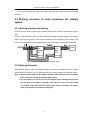
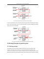
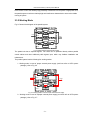
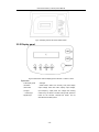
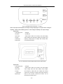
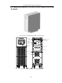
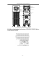
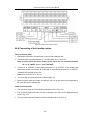
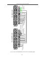
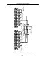
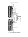
1
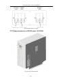
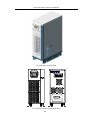
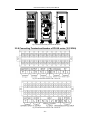
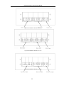
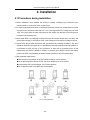
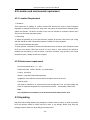
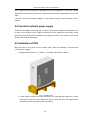
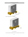
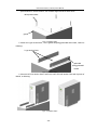
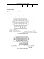
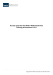
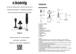
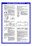
UPS FR-UK Series(
(1-15KVA)
)
Technical Manual
【NOTE】
】
Please carefully read the user’s manual before operation for the sake of
understanding correct operation of the instrument. Please keep the manual
handy for future reference.
WARNING
The input and output of the instrument is with danger high
voltages which may endanger the safety of life. Please strictly
follow the operating description is not allowed to remove the
cover of the instrument.
1. Please keep the instrument connect the ground before connecting instrument。
2. The input & output voltage of the instrument is dangerous which will endanger the safety of
life。
3. Please do not open the cover of the instrument by yourself in view of danger of shock。
4. Please turn off the mains input switch and the battery switch for any urgency。
5. There are many kinds of power sources for the instrument, the line bank or the socket may still
have voltage if only the main power is disconnected.
6. Please remove the cable between the battery & instrument before repairing. It’s necessary to
wait for another 5 minutes for discharging, because of the danger of shock.
7. The wires should be fastened to the terminals. It is prohibited to short the anode and cathode
of battery. It’s prohibited to touch any two of wire connectors or bare end of connecting wires.
Otherwise, it may lead to damage of battery or personal injury.
8. Please keep the battery and battery group away from the fire and all the instrument that may
cause spark to prevent the danger and damage。
9. Please do not open or shatter the battery, the overflow electrolyte is with causticity that may be
harmful to life.
10. Please contact the professional personnel of the local dealer or the special maintenance
station for any trouble-shooting. Random disposal of the trouble is not allowed.
11. This is an A-grade product with electromagnetic compatibility, it may make some radio
disturbance in environment. In this situation, users should adopt some actual and feasible
method for anti-interference.
12. The instrument should be maintained by the service professional.
13. Before usage, confirm that the temperature of the instrument has dropped into the normal run
range. It is recommended still placement for 24 hours in the normal temperature range before
startup.
14. Before you replace the battery of different brand and different type, make sure the charging
voltage is matching with UPS charging voltage due to the different required charging voltage of
different battery, If any doubt, please consult with the manufacturer.
Table of Contents
1. System Overview .......................................................................................................................... 1
1.1Explanation on Model Number............................................................................................... 1
1.2 Brief Introduction of Product ................................................................................................. 1
1.2.1 Product feature ........................................................................................................... 1
1.2.2 Technical Specification ............................................................................................... 3
2. Basic Principles and Structures ................................................................................................. 5
2.1 Working Principles of Single Unit .......................................................................................... 5
2.1.1 Working Principle Drawing ......................................................................................... 5
2.1.2 Working Principles ...................................................................................................... 5
2.1.3 Working Procedure ..................................................................................................... 6
2.2 Working principles of serial connection hot standby system ................................................ 7
2.2.1 Working principles and drawing.................................................................................. 7
2.2.2 Working Procedure ..................................................................................................... 7
2.3 Working Principles of parallel system ................................................................................... 8
2.3.1 Working mode ............................................................................................................. 8
2.3.2 Working Mode ............................................................................................................. 9
2.4 How to Choose the Parallel System or Serial Connection System .................................... 11
2.5 Shape and structure ............................................................................................................ 11
2.5.1 Display panel structure ............................................................................................. 11
2.5.2 Display panel ............................................................................................................ 12
2.5.3 Shape and structure of FR-UK10 series,FR-UK20L ................................................ 14
2.5.4 FR-UK10,FR-UK10L,FR-UK20L connecting terminal .............................................. 15
2.5.5 Shape and structure of FR-UK20,FR-UK30 series,FR-UK series(5~8KVA)....... 16
2.5.6 Connecting terminal and breaker of FR-UK20, FR-UK30 Series, FR-UKSeries
(5~8KVA) ........................................................................................................................... 17
2.5.7 Shape and structure of FR-UK series (10-15KVA) .................................................. 19
2.5.8 Connecting Terminal and breaker of FR-UK series (10-15KVA) ............................. 21
3.Transportation and storage ........................................................................................................ 24
3.1 Transportation ..................................................................................................................... 24
3.2 Storage ................................................................................................................................ 24
4. Installation ................................................................................................................................... 25
4.1 Precautions during installation ............................................................................................ 25
4.2 Location and environment requirement .............................................................................. 26
4.2.1 Location Requirement............................................................................................... 26
4.2.2 Environment requirement ......................................................................................... 26
4.3 Unpacking ........................................................................................................................... 26
4.4 Check the external power supply ........................................................................................ 27
4.5 Installation of UPS............................................................................................................... 27
4.6 Installation of battery cabinet .............................................................................................. 30
4.6.1 Important safety precautions .................................................................................... 30
4.6.2 Installation Procedures ............................................................................................. 30
4.7 Installation of Parallel System ............................................................................................. 30
4.8 Electrical wire connection ................................................................................................... 30
4.8.1 Selection of input breaker ......................................................................................... 30
4.8.2 Selection of the input and output cables .................................................................. 31
4.8.3 Connection of single unit .......................................................................................... 32
4.8.4 Connecting of hot standby system ........................................................................... 34
4.8.5 The Connection of Parallel System .......................................................................... 38
4.9 Checking and Testing of the System .................................................................................. 40
4.9.1 Check the Electrical Wire Connection ...................................................................... 40
4.9.2 UPS Testing .............................................................................................................. 40
4.10 Connect with the load ....................................................................................................... 40
5. Operation..................................................................................................................................... 41
5.1 Precautions during Operation ............................................................................................. 41
5.2 Before Turning on ............................................................................................................... 41
5.3 The Operation of Single Unit............................................................................................... 42
5.4 Operating Sequence of Parallel System ............................................................................. 42
5.4.1 Start up ..................................................................................................................... 42
5.4.2 Switching-off of parallel systems .............................................................................. 43
5.4.3 On-line Launching and Exit of Parallel Systems ...................................................... 43
5.4.4 Redundancy and Expansion of Parallel Systems .................................................... 43
6. Maintenance ................................................................................................................................ 44
6.1 Maintenance of Battery ....................................................................................................... 44
6.1.1 Daily Maintenance of Battery.................................................................................... 44
6.1.2 Replace the battery................................................................................................... 44
6.2 Maintenance Instructions ...................................................................................................... 1
6.2.1 Safety Precautions...................................................................................................... 1
6.2.2 Regular Preventive Maintenance ............................................................................... 1
6.2.3 Analysis and Solution to Common Problems ............................................................. 1
6.3 Trouble-shooting ................................................................................................................... 2
6.3.1 General Description .................................................................................................... 2
6.3.2 Trouble-shooting ......................................................................................................... 3
UPS FR-UK Series (1~15KVA) User’s Manual
1. System Overview
1.1Explanation on Model Number
There are two types of the FR-UK series (1~15KVA) UPS,one type is FR-UK series (1~8KVA) and
the other type is FR-UK series(10~15KVA)。
The description of FR-UK series(1~8KVA)and FR-UK series(10~15KVA)are showed as per Fig.
1-1 & 1-2。
FR-UK ** L
Type of Long Delay
Output Capachity
FR-UK Series Oneline UPS
Fig. 1-1 Explanations on the Meanings of FR-UK series (1~8KVA) Model Numbers
As showed in Fig.1-1,The “FR-UK” means the FR-UK series on-line UPS;“**”means the output
power of the FR-UK series(1~8KVA)products,When it is“30”,it means that the output power is
3000VA;“L” means that this products is with long back up time, and the one without “L” means that
the product is the standard type。
Output Capacity
Output Phase
Intput Phase
Paralleded Type
FR-UK Series Oneline UPS
Fig.1-2 Explanations on the Meanings of FR-UK series (10~15KVA) Model Numbers
As showed in Fig.1-2,The “FR-UK”means the FR-UK series on-line UPS;“/B”shows that the
product is available for parallel operation,without“/B”means that the product is standard type;the
input item“3”means three phase input,“1”means single phase input;the output item“1”means
single phase output,“3”means three phase output;output capacity item“**”,means the output
capacity of the product,When it is“10”,it means that the output capacity is 10KVA。
1.2 Brief Introduction of Product
1.2.1 Product feature
FR-UK(1~15KVA)series UPS is the high performance sine wave on-line UPS, specially designed
-1-
UPS FR-UK Series (1~15KVA) User’s Manual
for the network computer and mini-intellectual instrument (for example: testing equipment,industrial
automatic
instrument
etc),nicety
apparatus
of
such
systems
like
finance,communication,insurance,railway,medical treatment,mine,enterprise etc which is particular
suitable for bad electric environment。
FR-UK(
(1~15KVA)
)series UPS is sine wave on-line high performance uninterruptible power
supply with the following features:
True on-line double conversion structure design
Input and Output are isolated with transformer
Broad Input Voltage Range
The input voltage is 165~275Vac (285~475Vac for three phase),when the load are PC, the input
voltage and frequency is even broader. It can work with village utility and oil generator
LCD Display Panel
Gently touch the button, the UPS input voltage, output voltage, load capacity, battery voltage can
be clearly display on panel.
Accurate Synchronized Utility System
Output voltage frequency has zero phase synchronize with net frequency. It fully meets many
equipments requirements on synchronized power frequency with power net, improve the realibility.
Completed Protection Measurement
Over voltage protection, over current protection, battery low voltage, instant limited current and
short circuits protection etc. these keep the machine away from the wrong operation, and ensure it
works reliably in any conditions.
Intelligent RS232 Communication Function(
(Options)
)
RS232 communication port supporting power software, the power net and UPS status can be
monitored on computer. In additional, it also support SNMP adapter, realize the network
management, improve the reliability of the system.
None-Principle-subordinate adaptive control technique (Only applicable to the parallel
UPS)
Adapt none-principl-subordinate adaptive control technique, realize N units parallel or N+1
redundancy parallel connection, improve the reliability of the system. It realizes UPS unit on-line
launch or quite an heat maintenance for the system.
-2-
UPS FR-UK Series (1~15KVA) User’s Manual
1.2.2 Technical Specification
Table 1-1 FR-UK series(1~8KVA)Technical specification
Model
Specification
FR-UK10/
FR-UK20/
FR-UK10L
FR-UK20L
range
Input
FR-UK30L
FR-UK50L
FR-UK60L
165~ 275
50± 5%
Phase
Single phase three wires
Generator
tracing
tracing the generator when 47~53Hz
function
Battery
voltage
48
(VDC)
Rated power (VA)
1000
96
2000
3000
6000
Sine wave,THD<3%
Wave form
Switch time (ms)
Overload capacity
0
125% of rated load last for 60 second,150% of rated load last for 0.5 second
Three output sockets /Two output sockets +
Output mode
LCD display input voltage, output voltage, load capacity, battery voltage.
LED indicating lights show the working mode
Alarm function
Protection function
Communication
overload, AC input abnormal, low battery
low battery, overload, over temperature, short circuit, output voltage, output low voltage
RS232 communication port support power software,and support SNMP adapter to realize
function(Optional)
Remote
Connecting terminal
connecting terminal
Display panel
control
the network management
independent digital remote control at the distance of 1000 meters supported by RS485,
(Optional)
which realizes remote monitor safe and easy.
Port communication
the port allow to through 2A currency, convenient and safe
(Optional)
Backup time
10 minutes/
5 minutes/any configuration
Battery efficiency
any configuration
>84%
>87%
Working
0~40℃
temperature
0~95%(no condensation)
Relative humidity
Altitude
Meet GB/T 7260.3-2003 standard
Noise (dB)
≤55
(mm)
230×635×690
23 0×62 0 ×4 70
(W×L×H)
Weight
5000
50±0.5%(battery mode)
Frequency (Hz)
Dimension
192
220,Isolated transformer output
Voltage range(Vac)
output
FR-UK60/
50±6%
(Hz)
Other features
FR-UK50/
160~ 280
Voltage range (Vac)
Frequency
FR-UK30/
(Kg)
48/ 36
230×635×690
230×620×470
74/49
-3-
82/56
90/ 52
91/ 53
UPS FR-UK Series (1~15KVA) User’s Manual
Table 1-2 FR-UK Series(10~15KVA)Technical specification
Model
Specification
FR-UK80L
FR-UK1115/
FR-UK3110/
FR-UK3115/
FR-UK/B1110
FR-UK/B1115
FR-UK/B3110
FR-UK/B3115
165~275
Voltage range (Vac)
Input
FR-UK1110/
Frequency range (Hz)
50±5%
Phase
single phase three wires
Battery voltge (VDC)
Rated power(KVA)
Output
Frequency (Hz)
Three phases five wires
192
8
10
15
10
15
220±2%,isolated transformer output
Voltage range (Vac)
Automatic synchronous tracing when power supply normal, at 50±0.5% when power
supply abnormal
Sine wave,THD<3%
Wave form
Switch time (ms)
0
Overload capacity
125% of rated load last for 60 seconds,150% of rated load last for 0.5 seonds
Output mode
Connecting terminal
≤5%(only applicable to the parallel models)
Parallel equal current
Panel
LCD panel display input voltage, output voltage, load capacity, battery voltage.
display
LED indicating lights show the working status
Alarm
mains supply abnormal, low battery, over load
Protection function
Communication
protection for low battery, over load, over temperature, short circuit, output over voltage,
output low voltage
RS232 communication port support power software,and support SNMP adapter to
function(optional)
Remote
control
realize the network management
independent digital remote control at the distance of 1000 meters supported by RS485,
(optional)
Other features
285~475
Port
which realizes remote monitor safe and easy.
communication
the port allow to through 2A currency, convenient and safe
(Optional)
Parallel function
random extending or N+1 redundancy parallel connection(only applicable to the parallel
models)
Back up time
Any configuration
Battery efficiency
>89%
Intellectual MMBM battery control technique, unique multi-charging mode uprising the
Charging
reliability and lengthen life of the battery
Work temperature
0~40℃
Relative humidity
0~95%(no condensation)
Altitude
Meet GB/T 7260.3-2003 standard
Noise (dB)
<60
Dimension
(mm)(W×L×H)
Weight
(Kg)
2 3 0× 6 3 5 × 6 9 0
300×740×700
4 0 0× 8 0 0 × 1 1 8 0
3 0 0× 7 4 0 × 7 0 0
4 0 0 × 8 0 0 × 1 18 0
70
92
155
130
160
◆ Specification are subject to change without prior notice
-4-
UPS FR-UK Series (1~15KVA) User’s Manual
2. Basic Principles and Structures
2.1 Working Principles of Single Unit
2.1.1 Working Principle Drawing
Fig. 2-1 Working Principles Block Diagram of FR-UK series
2.1.2 Working Principles
FR-UK series UPS includes:
FR-UK series UPS includes: AC-DC converter, DC-AC inverter, charger, control drive circuits,
synchronize bypass switch, battery group, LCD display control etc. the high performance UPS has
strict requirement on anti-interference etc. Thus, its choiceness circuits and component ensure all
sections have more voltage and current redundancy. Especially, it adapts IGBT, which has
excellent high temperature on current and bring high performance.
AC-DC Conversion: convert the AC current from power network into DC current by lowering the
voltage in the coupling transformer, whole wave rectifying and filtering, before being supplied to
inverted circuits. AC-DC input is done by soft starting circuits, preventing the impact to the power
network upon turning on.
DC-AC Conversion Circuits: using high powered IGBT module whole bridging conversion circuits,
with very high surplus power, especially low output resistance within active output scope,
characteristic of quick responses. Using high frequency adjusted current-limiting technology,
powered IGBT module reliable high current limit is confirmed, Thus making the inverter safe and
reliable no matter there is sudden change in power supply voltage or loading impact.
Drive control: drive control is the core to fulfilling whole machine function control. It carries out the
control over SPWM sine pulse width adjustment as well as the provision of detection, protection,
synchronism, switches and driving signal displays. Since dual voltage feedback is employed under
static and active conditions, the active features and reliability of the inverter is greatly improved.
-5-
UPS FR-UK Series (1~15KVA) User’s Manual
2.1.3 Working Procedure
In Case of proper external power supply, there is DC voltage in the DC main circuit fro DC/AC
inverter to output steady 230V AC voltage. And external power supply will charge the battery at the
same time. In case of low voltage or sudden failure of external power supply, the battery supplies
power to the DC circuit through the isolating diode. There is no switching interval from grid power
supply to battery power supply. When battery is nearly out of power, UPS will give out light and
sound alarm; restrict the inverter’s operation and give out long sound alarms while the battery is
discharging electricity. UPS also has over-load protection function. In case of overload (125%
rated load), the UPS will switch to bypass status, and come back when the load is normal. In case
of severe overload (≥150% of rated load), the UPS will stop immediately inverter output and switch
to bypass status while the UPS breaker may also switch off automatically. When fault is eliminated,
switch on UPS and resume operation. When UPS is abnormal, it will give out sound and light
alarm, the UPS have alarm and protection function.
Table 2-1 Abnormal status and alarm protection function
UPS status
Buzzer
Panel lights
Protection/Alarm
Inverter light on, line light off,
Normal
Silent
None
bypass light off, fault light off
Overload≥100%
Beeping
every
2
seconds
Overload≥110%
Overload≥125%
Overload≥150%
Beeping
Inverter light on, bypass light
Alarm
off, fault light off
every
1
Inverter light on, bypass light
Alarm
second
off, fault light off
Long Beeping
Bypass light on, inverter light
Protection after one
off after 1 minute, fault light on
minute
Inverter light off, bypass light
Protection
Long Beeping
on, fault light on
Battery voltage to alarm point
Battery voltage to protection point
Beeping every 1.5
Inverter light on, line light off,
seconds
bypass light off, fault light off
Long Beeping
Inverter light off, line light off,
Alarm
Protection
bypass light on, fault light on
utility input abnormal
Over temperature
Beeping
every
5
line light off, inverter light on,
seconds
bypass light off, fault light off
Silent
Inverter light off, line light off,
Alarm
Protection
bypass light on, fault light off
Output over voltage, output low
Long Beeping
Inverter light off, bypass light
voltage, short circuit
on, fault light off
-6-
Protection
UPS FR-UK Series (1~15KVA) User’s Manual
The UPS will start up and charge the battery when the utility come back after low battery
protection.
2.2 Working principles of serial connection hot standby
system
2.2.1 Working principle and drawing
Connect the main UPS’s bypass input to standby UPS output, instead of external power supply
input
In case of main UPS failure, the main UPS is switched to bypass status and standby UPS supplies
power to the load, the load is in UPS inverter protection, so the equipment can run safely. If the
main UPS is in bypass status and the standby UPS failure, the utility supplies power to the load.
Utility
Ni
Bypass
input
Bypass
input
Standby
UPS
Main
UPS
Main input
Main input
Load
No
Fig. 2-2 Principle Diagram of Hot Standby System
2.2.2 Working Procedure
While working properly, main UPS supplies power to the load and standby UPS idly runs hot
standby system. As show in Fig. 2-3, thick lines refer to the power passage of hot standby system
Note: 1. the two units of UPS by hot standby connection mode shall not share one battery
pack, instead, they shall have separate battery packs
2. The AC input(L1,L2,L3,N) of main UPS, the bypass input of standby UPS (L,N) and
the AC input (L1,L2,L3,N) of standby UPS should be from the same utility
(L1,L2,L3,N), at the same time, the order of phas must be consistent. The bypass
input (L,N) should be connected to utility(L2,N).
-7-
UPS FR-UK Series (1~15KVA) User’s Manual
Fig. 2-3 Power Flow Chart of UPS Hot Standby in Normal Condition
In case of main UPS failure, the main UPS is switched to bypass status and standby UPS supplies
power to the load. As show in Fig.2-4, the thick lines refer to the power passage of hot standby
system in case of main UPS failure.
Fig. 2-4 Power Flow Chart of Hot Standby System in case of Main UPS Failure
2.3 Working Principles of parallel system
2.3.1 Working principle
The realization of AC power supply’s paralleling and balanced current is through the rapid
regulation of the single unit’s AC output wave, amplitude and phase to make them in strict
conformity to one another and for the purpose of balanced current. Any voltage amplitude or phase
difference will create very big circumference which in serious case may cause overload or damage
-8-
UPS FR-UK Series (1~15KVA) User’s Manual
to the inverter. Due to the relatively high possibility of interference to the power of high-power UPS,
the parallel system must have relatively high anti-interference characteristic to ensure the reliable
running of system.
2.3.2 Working Mode
Fig. 2-5 shows block diagram of the parallel system
BYPASS
AC
LINE
DC
DC
AC
BATTERY
UPS1
LOAD
BYPASS
AC
DC
DC
AC
BATTERY
UPS2
Fig. 2-5 Block Diagram of the Parallel System
The parallel unit has a separate bypass. Two UPSs can be paralleled directly without parallel
control cabinet and other additional public bypass input, which may facilitate installation and
maintenance.
The parallel system has the following four working modes
1. Working mode in case of proper external power supply (real lines refer to UPS’s power
passage), refer to Fig. 2-6
BYPASS
AC
LINE
UPS1
DC
DC
AC
BATTERY
LOAD
BYPASS
AC
UPS2
DC
DC
AC
BATTERY
Fig. 2- 6 Working Mode in case of Proper External Power Supply
2.Working mode in case of improper external power supply (real lines refer to UPS’s power
passage), refer to Fig. 2-7
-9-
UPS FR-UK Series (1~15KVA) User’s Manual
BYPASS
AC
LINE
DC
DC
AC
BATTERY
UPS1
LOAD
BYPASS
AC
DC
DC
AC
BATTERY
UPS2
Fig. 2- 7 Working Mode in case of Improper External Power Supply
3. Working mode in case of system overload (real lines refer to UPS’s power passage), refer
to Fig. 2-8
BYPASS
AC
LINE
DC
DC
AC
BATTERY
UPS1
LOAD
BYPASS
AC
DC
DC
AC
BATTERY
UPS2
Fig. 2- 8 Working Mode in case of System Overload
4. Working mode in case of one machine of the system is abnormal (real lines refer to UPS’s
power passage), refer to Fig. 2-9. The abnormal machine has no output, while the normal
one supply the power.
natural
machine
BYPASS
AC
LINE
UPS1
DC
DC
AC
BATTERY
LOAD
BYPASS
AC
abnormality
machine
UPS2
DC
DC
AC
BATTERY
Fig. 2- 9 Working Mode in case of one machine abnormality
- 10 -
UPS FR-UK Series (1~15KVA) User’s Manual
2.4 How to Choose the Parallel System or Serial Connection
System
It is suggested to choose serial connection system or parallel system, when the capacity of user’s
need is smaller, and need to advance the system reliability.
It is commonly suggested to choose paralleled system, when the capacity of user’s need is larger.
Paralleled system can be used for free as N piece paralleled to enlarge capacity or N+1 piece
paralleled, in this way the system reliability can be greatly enlarge. And it also can be jumped into
or drop out on line for free, as realizing maintenance on line of paralleled system
FR-UK series 2~5KVA (not include 5KVA) standard UPS is mainly used for single unit system;
5KVA and above 5KVA UPS can be used for single unit system or serial connection hot standby
system; 10KVA and above 10KVA UPS can be used for parallel system. It should be put forward
when order if the user needs the parallel system.
2.5 Shape and structure
2.5.1 Display panel structure
Fig.2-10 Display panel of the FR-UK(1~10KVA)series
- 11 -
UPS FR-UK Series (1~15KVA) User’s Manual
Fig.2-11 Display panel of the FR-UK 15KVA series
2.5.2 Display panel
Fig.2-12 Stand-alone machine display panel of FR-UK(1~10KVA)series
Explanation:
℃,LCD Display panel
℃,fault light
℃,ON button
℃,Select button: When work normally, LCD panel display
℃,OFF button
output voltage. Press this button, display output voltage,
℃,line light
input frequency, output power, DC voltage, UPS working
℃
mode one by one. When in inverter working mode, press this
Inverter light
℃,Bypass light
button for two seconds, eliminate the buzzer, but not
eliminate the low battery alarm.
- 12 -
UPS FR-UK Series (1~15KVA) User’s Manual
Fig. 2-13 paralleled machine of FR-UK(1~10KVA)
Note: If the input is three-phase, the output voltage displaying on the panel is the voltage of
B-phase; if there is hot standby system, it is the voltage of standby unit output voltage.
Explanation:
℃,LCD display panel
℃,fault light
℃,ON button
℃,parallel light
℃,OFF button
℃,Select button: When work normally, LCD panel display
℃,line light
output voltage, press this button, display input voltage, input
℃,inverter light
frequency, output power, DC voltage, UPS working mode,
℃,bypass light
can’t eliminate the buzzer.
Fig. 2-14 Stand-alone machine display panel of FR-UK 15KVA series
Explanation:
℃,LCD Display panel
℃,fault light
℃,ON button
℃,Select button: When work normally, LCD panel display
℃,OFF button
output voltage. Press this button, display output voltage,
℃,line light
input frequency, output power, DC voltage, UPS working
℃
mode one by one. When in inverter working mode, press this
Inverter light
℃,Bypass light
button for two seconds, eliminate the buzzer, but not
eliminate the low battery alarm.
- 13 -
UPS FR-UK Series (1~15KVA) User’s Manual
Fig. 2-15 paralleled machine of FR-UK 15KVA
Explanation:
℃,LCD display panel
℃,fault light
℃,ON button
℃,parallel light
℃,OFF button
℃,Select button: When work normally, LCD panel display
℃,line light
output voltage, press this button, display input voltage, input
℃,inverter light
frequency, output power, DC voltage, UPS working mode,
℃,bypass light
can’t eliminate the buzzer.
2.5.3 Shape and structure of FR-UK10 series,FR-UK20L
Fig. 2-16 the form of FR-UK10/ FR-UK10L/ FR-UK20L
- 14 -
UPS FR-UK Series (1~15KVA) User’s Manual
SNMP
SNMP Interface
(options)
RS232
POWER
NFB2
ON
BATTERY
NFB1
OFF
AC input air breaker
DC input air breaker
RS232 Interface
OUTPUT
Output socket
! CAUTION
When connect wires,please remove the cover-board;
And when working is done,please make sure lock up the cover-board.
LCD Display
Line bank cover
Line bank
Wires tied ring
Fan
Fig. 2-17 the front and rear panel of FR-UK10/ FR-UK10L/ FR-UK20L
2.5.4 FR-UK10,FR-UK10L,FR-UK20L connecting terminal
Fig. 2-18 line bank of FR-UK10/ FR-UK10L/ FR-UK20L
- 15 -
UPS FR-UK Series (1~15KVA) User’s Manual
2.5.5 Shape and structure of FR-UK20,FR-UK30 series,FR-UK series
(5~8KVA)
)
Fig. 2-19 the form of FR-UK20, FR-UK30/30L, FR-UK(5~8KVA)
SNMP
SNMP
interface
(options)
PALL.
BATTERY POWER
NFB1
NFB2
SINGAL
RS232/485
BYPASS
NFB3
RS232/RS485
Communication interface
Paralleled interface
AC input air
breaker
battery air
breaker
LCD display
! CAUTION
When connect wires,please remove the cover-board;
And when working is done,please make sure lock up the cover-board.
Line bank cover
Line bank
Wires tied ring
Fan
Fig. 2-20 the front and rear panel of FR-UK20,FR-UK30/30L
- 16 -
UPS FR-UK Series (1~15KVA) User’s Manual
SNMP
SNMP interface
(options)
PALL.
BATTERY POWER
NFB1
NFB2
DC input are
breaker
AC input air
breaker
LCD dispaly
SINGAL
RS232/485
BYPASS
NFB3
RS232/RS485
Communication interface
Paralleled interface
Bypass air breaker
! CAUTION
When connect wires,please remove the cover-board;
And when working is done,please make sure lock up the cover-board.
Line bank cover
Line bank
Wires tied ring
Fan
Fig. 2-21 the front and rear panel of FR-UK(5~8KVA)
2.5.6 Connecting terminal and breaker of FR-UK20, FR-UK30 Series,
FR-UK Series (5~8KVA)
Fig. 2-22 line bank of FR-UK20/FR-UK30
- 17 -
UPS FR-UK Series (1~15KVA) User’s Manual
Fig. 2-23 line bank of FR-UK30L
Fig. 2-24 line bank of FR-UK50L,FR-UK60L,FR-UK80L
Fig. 2-25 breaker of FR-UK20/FR-UK30/FR-UK30L
- 18 -
UPS FR-UK Series (1~15KVA) User’s Manual
Fig. 2-26 breaker of FR-UK(5~8KVA)
2.5.7 Shape and structure of FR-UK series (10-15KVA)
Fig. 2-27 the form of FR-UK 10KVA
- 19 -
UPS FR-UK Series (1~15KVA) User’s Manual
Fig. 2-28 the form of FR-UK 15KVA
SNMP
PALL.
SIGNAL
POWER
NFB1
RS232/485
BYPASS
NFB2
BATTERY
NFB3
! CAUTION
When connect wires,please remove the cover-board;
And when working is done,please make sure lock up the cover-board.
Fig. 2-29 the front and rear panel of FR-UK 10KVA
- 20 -
UPS FR-UK Series (1~15KVA) User’s Manual
LINE
LI NE
INVE RTER
I NV ER TER
BY PASS
BYP ASS
FAULT
FAUL T
ON
ON
SEL EC T
FAN
SELECT
OF F
OFF
PALL
SIGNAL
PALL.
SIGNAL
RS232/485
SNMP
RS232/RS485
SNAP
BATTERY
PYPASS
POWER
电 池
BATTERY
旁 路
BYPASS
市 电
POWER
FAN
Fig. 2-30 the front and rear panel of FR-UK 15KVA
2.5.8 Connecting Terminal and breaker of FR-UK series (10-15KVA)
Fig. 2-31 the line bank of FR-UK(/B)1110/1115
Fig. 2-32 the line bank of FR-UK(/B)3110/3115
- 21 -
UPS FR-UK Series (1~15KVA) User’s Manual
Fig. 2-33 the breaker of FR-UK(/B)1110
Fig. 2-34 the breaker of FR-UK(/B)1115
Fig. 2-35 the breaker of FR-UK(/B)3110
- 22 -
UPS FR-UK Series (1~15KVA) User’s Manual
Fig. 2-36 the breaker of FR-UK(/B)3115, 1115
- 23 -
UPS FR-UK Series (1~15KVA) User’s Manual
3.Transportation and storage
3.1 Transportation
It should strictly conform to the care signs during transportation, and place the UPS according to
the care signs, to avoid the shake to the UPS. It can’t put the equipment on the open vehicle and
cabin, and should be put together with flammable articles. It is prohibited to put the equipment in
the open air in the midway, and should avoid the drench of the rain, snow or other wet goods, also
machinery damage.
3.2 Storage
Place the equipment according to the care signs. It should part from ground for 20cm, part from
wall, hot source, cold source, windows or air entrance for 50cm
Environment temperature for storage is 0~40℃, relative humidity is 20%~80%, the stock should
not have any baleful gas, flammable and corrosive chemistry, have not strong shake, strike and
magnetic field. The storage period in this condition is for six months, over six months, the
equipment should be checked, and charge the battery every three months.
- 24 -
UPS FR-UK Series (1~15KVA) User’s Manual
4. Installation
4.1 Precautions during installation
1. Before installation, check whether the circuitry is smooth, including every connection point,
electrical outlet, to avoid open circuit or short circuit.
2. For input single phase three wires, it should well grounded, ensure the voltage between neutral
and ground wire should be lower than 5V, if it is not well grounded, the voltage may be reach
100V. If the users have the strict requirement on the voltage, pay attention to the well ground,
to avoid any unnecessary loss.
3. When install UPS, it is prohibited to connect the input and output neutral wires, live wires, and
ground wires wrongly, to avoid short circuit. In the meantime check the input voltage is normal.
4. Please follow the provided instructions and sequences while installing the battery. The wires
should be fastened to the terminals. It is prohibited to short the anode and cathode of battery. It
is prohibited to touch any two of wire connectors or bare end of connecting wires. All the
misconducts may lead to damage of battery or personal injury. Before connect the battery
packs to the UPS, check whether the battery voltage conforms to the UPS specification.
5. UPS installation requirement:
UPS must be evenly placed on the floor (avoid slanting or uneven ground);
Do not place articles on the top of UPS, No one is allowed to sit on top of UPS.
Avoid placing UPS in direct sunlight, rain or humid grounds.
Do not place the UPS in any place with erosive gases.
Fig. 4-1 UPS placement
- 25 -
UPS FR-UK Series (1~15KVA) User’s Manual
4.2 Location and environment requirement
4.2.1 Location Requirement
1. Clearance
There should be no garbage or sundries around UPS because the liquid or metal improperly
deposited or suddenly fall down from other place may cause UPS short-circuit endanger power
system and operator. The dust or sundries on the vent can clumber air circulation influence fan’s
work or may shut down the power system.
2. Fireproofing
To lessen the possibility of on fire and reduce the expense to the least, UPS room’s wall, ceiling
and floor should be made of fireproofing material. Portable CO2 fire extinguisher
3. Air circulation and heat elimination
To easily operator, maintenance Inverter and eliminate Inverter inner heat, there should be at least
50-70 cm room around UPS frame and 50 cm room above it. Also electronic fan should be
installed near the battery to keep the house in good air circulation. Only operate in the normal
temperature (20°C), battery life will be the longest.
4.2.2 Environment requirement
Environment temperature:0℃~+40℃;
Relative humidity:0%RH~95%RH,no condensation;
Cooling:Air-cooled;
Altitude:meet GB/T 7260.3-2003 standard;
Uprightness: there shall be no shock and the inclination shall no be over 5º;
Pollution grade:℃。
UPS must be installed in an environment that has enough wind, cool, not high humidity and
clean air. Operation temperature for recommended is 20~25℃, and humidity is about 50%.
Note:
It is prohibited to be installed in an environment that has metal electric dust.
4.3 Unpacking
Both UPS and its fittings (battery) are packaged in wooden cases or cartons, so when unpack the
UPS, the operator should be careful and see if there is any damage. Before clear away the
package material, make sure all the fittings have been found.
- 26 -
UPS FR-UK Series (1~15KVA) User’s Manual
If the equipment and its fittings have damaged during the transportation or are not fit with the
goods listed in the contract, please note on spot and contact with the representative of our local
office.
If the UPS are found machinery damage, or the external damage, further inspection will be
needed.
4.4 Check the external power supply
Check the load capacity of the power net, to ensure it can meet the equipment’s requirement, and
to make sure it conforms to the voltage and frequency on the equipment’s name plate. Check
whether the load capacity decline because of the aging of the wire. If any doubt, please consult
with the local electricity department.
4.5 Installation of UPS
Move the UPS to the ground from the wooden pallet. Take the installation of FR-UK series
(10-15KVA) for example.
1. Unpack the FR-UK series(1~10KVA),the shape and structure is below:
Fig.4-2 installation step 1
2. Firstly release six (three in the left and three in the right) M8 bolts where the L anchor
frame joins the main unit, then release four (two in the left and two in the right) M8 bolts
where the feet joins the wooden pallet, as following:
- 27 -
UPS FR-UK Series (1~15KVA) User’s Manual
Bolt M8×30
Bolt M8×100
Fig.4-3 installation step 2
3. Remove L type anchor frame, as following:
Fig.4-4 installation step 3
4. Select and arrange the installation location, drive 4 M8 expansion bolts into the ground,
- 28 -
UPS FR-UK Series (1~15KVA) User’s Manual
space between is 301mm×360mm, the revealed height should be within 50mm
M8 expansion bolts
ground
Fig.4-5 installation step 4
5. Mount the L type anchor frame,fix the gasket Φ8,spring gasket Φ8 and nut M8,fasten as
following:
L type anchor frame
gasket Φ8
spring gasketΦ8
nut M8
Fig.4-6 installation step 5
6. Move the UPS into anchor frame, and fix the main UPS with anchor frame with 4 pieces of
M8×30, as following:
Fig.4-7 installation step 6
- 29 -
UPS FR-UK Series (1~15KVA) User’s Manual
4.6 Installation of battery cabinet
For the long time UPS and 10~15KVA UPS, They would be matched battery and battery cabinet
except the main unit.
4.6.1 Important safety precautions
It is prohibited to prize up or break down the battery, because the electrolyte do harm to our skin
and eyes. Please advert the following safe precautions when replacing the battery to avoid to get
an electric shock and short circuit.
1)
Don’t gird the watch, ring or any other metal decorations.
2)
Using the tools with insulated holds.
3)
Don’t put tools and metal articles on the battery.
4)
Keep the fire source away from the battery, no smoking.
4.6.2 Installation Procedures
1. To ensure safe operation and avoid the damage to the equipment, It is required to install the
battery by professional personnel, and implement the following procedures:
1)
Connect the external battery packs, don’t join into the UPS battery input terminal.
2)
Connect the AC Wire into UPS, ensure the polar is correct and the voltage conforms to
the UPS technical specification.
2. Turn on UPS when AC input normal and UPS empty load, check the DC voltage in battery input
terminal.
3. Turn off UPS after checking the charging voltage is normal, join the battery packs, and ensure
the polar is correct of UPS and battery cabinet.
4. Check everything is OK after mounting.
4.7 Installation of Parallel System
1. Assemble the single unit of parallel system separately according to the above installation
procedure, then connect the single unit’s AC output to the distribution box.
Note: the connection and phases of single unit AC input should be strictly consistent, and the
bypass phases of the parallel system should be identical.
2. Connect all the parallel port with the communication wires, and fasten the RS232 with the bolts
4.8 Electrical wire connection
4.8.1 Selection of input breaker
To isolate with the utility, the breaker or distribution box with the adaptive power should be
- 30 -
UPS FR-UK Series (1~15KVA) User’s Manual
equipped before the equipment’s input wire. The breaker should be 1.5~2 times of the UPS
maximal input currency, and can’t adopt the breaker with the creepage protection, to avoid the
wrong operation. It is suggested to make the distribution box by the professional company, please
refer the selection of breaker to Table 4-1
FR-UK10(L)
FR-UK20(L)
FR-UK30(L)
maximal
recommende
maximal
recommende
maximal
recommende
currency(A) d breaker(A) currency(A) d breaker(A) currency(A) d breaker(A)
AC input
18
DC input
23
32
25/32
50/100
43
50
17/23
50/50
30
FR-UK50(L)
FR-UK60(L)
100
50
FR-UK80L
AC input
DC input
maximal
recommende
maximal
recommende
maximal
recommende
currency(A) d breaker(A) currency(A) d breaker(A) currency(A) d breaker(A)
51
100
67
100
86
150
35
100
47
100
59
150
AC input
DC input
maximal
recommende
maximal
recommende
maximal
recommende
currency(A) d breaker(A) currency(A) d breaker(A) currency(A) d breaker(A)
128
200
28
100
43
100
87
150
59
150
87
150
FR-UK1110
FR-UK1115
FR-UK3110
FR-UK3115
AC input
DC input
maximal
recommende
currency(A) d breaker(A)
95.5
125
69
125
Table 4-1 choice of air breaker
4.8.2 Selection of the input and output cables
The selection of UPS AC input cable, output cable and battery connecting cable, please refer to
the recommended sections listed in Table 4-2
2
Table 4-2 choice of cables area(mm )
FR-UK10(L)
FR-UK20(L)
FR-UK30(L)
AC input(live, neutral)
1.5
2.5
4
AC input(ground)
1.5
1.5
2.5
DC input(+, -)
2.5
6
4
AC output(live, neutral)
1.5
1.5
1.5
AC output(ground)
1.5
1.5
1.5
FR-UK60(L)
FR-UK80L
FR-UK1110
AC input(live, neutral)
10
16
16
AC input(ground)
10
10
10
DC input(+, -)
6
10
16
AC output(live, neutral)
6
10
16
AC output(ground)
6
10
10
FR-UK3110
FR-UK3115
AC input(L1\L2\L3\N)
16
25
AC input(ground)
10
10
DC input(+, -)
16
25
- 31 -
FR-UK50(L)
6
6
6
4
4
FR-UK1115
25
10
25
25
10
UPS FR-UK Series (1~15KVA) User’s Manual
AC output(live, neutral)
AC output(ground)
16
10
25
10
The above section is for the wire about 5m, if the wire is above 20m, the section should be
increased accordingly.
4.8.3 Connection of single unit
Connect the provided cables into the corresponding terminal and fasten.
Note: Ensure the connection of input wire and output wire, input terminal and output terminal is
fasten, don’t connect badly and wrongly.
Fig.4-8 connection of FR-UK(1-3KVA)L
Fig.4-9 connection of FR-UK(1-3KVA)
- 32 -
UPS FR-UK Series (1~15KVA) User’s Manual
OUTPUT
BATTERY
-
+
N
L
INPUT
N
GND
L
BY
BYPASS
N
L
N
short wires been
connected before
L
the anode of battery
the cathode of battery
the live wire of output
the neutral wire of output
the live wire of bypass
the neutral wire of bypass
the ground wire of
input & output
the neutral wire of input
the live wire of input
Fig.4-10 connection of FR-UK50L/FR-UK60L/FR-UK80L
OUTPUT
N
L
INPUT
N
GND
L
BY
BYPASS
N
L
N
short wires been
connected before
L
the live wire of bypass
the live wire of output
the neutral wire of output
the neutral wire of bypass
the ground wire of
input & output
the neutral wire of input
the live wire of input
Fig.4-11 connection of FR-UK50/FR-UK60
BATTERY
+
-
OUTPUT
L
N
INPUT
N
L
GND
BYPASS
N
L
BY
N
L
short wires been
connected before
the anode of battery
the cathode of battery
the live wire of output
the neutral wire of output
the neutral wire of input
the live wire of input
the live wire of bypass
the neutral wire of bypass
the ground wire of
input & output
Fig.4-12 connection of FR-UK1110/1115
- 33 -
UPS FR-UK Series (1~15KVA) User’s Manual
Fig.4-13 connection of FR-UK3110/3115
4.8.4 Connecting of hot standby system
4.8.4.1 Connecting steps
1
Dismantle the terminal’s covering board of main UPS and standby UPS.
2
Cancel the wires connection between “L”,“N”of “BYPASS” and“L”,“N”of “BY”
Note: for three phases five wires models, please cancel the wire connection between
“N”,“L2”of “INPUT” and “L”,“N”of “BYPASS”.
3
Connect “L” of “BYPASS” in main UPS terminal and “L” of “OUTPUT” in the standby UPS
terminal by red wire; and connect “N” of “BYPSS” in main UPS terminal and “N” of “OUTPUT”
in standby UPS terminal by blue wire
Note: be sure not connect “L” and “N”.
4
5
The remaining connecting is the same with the single unit.
Check the above steps and confirm everything is OK, lock up the terminal covering board on
the main UPS and the standby UPS.
4.8.4.2 Connecting mode
1
The connecting mode of FR-UK 50/60 hot standby as show in Fig. 4-14.
2
The connecting mode of FR-UK1110/1115 hot standby is the same as FR-UK50L/60L/80L,as
show in Fig. 4-15.
3
The connecting mode of FR-UK3110/3115 hot standby as show in Fig. 4-16.
- 34 -
- 35 -
L
N
OUTPUT
L
GND
N
L
BYPASS
N
BY
L
L
N
OUTPUT
N
L
INPUT
GND
N
L
BYPASS
the main unit
the ground
wire of
the live wire of output
input &
the neutral wire of output
the neutral wire of input
output
the live wire of input
short wires been
connected before
the live wire of bypass
the neutral wire of bypass
the ground wire of input & output
the live wire of input
the neutral wire of input
N
INPUT
the standby unit
L
short wires that
should be
dismantled
N
BY
UPS FR-UK Series (1~15KVA) User’s Manual
Fig.4-14 connection of FR-UK50/60 hot standby system
L
N
OUTPUT
the anode of battery
the cathode of battery
+
BATTERY
L
GND
N
L
BYPASS
N
BY
L
short wires been
connected before
+
-
BATTERY
L
N
OUTPUT
N
L
INPUT
GND
N
L
BYPASS
the main unit
the ground
the live wire of bypass the anode of battery
the cathode of battery
wire of
the neutral wire of bypass
the live wire of output
the ground wire of input & output
input &
the neutral wire of output
the live wire of input
the neutral wire of input
output
the neutral wire of input
the live wire of input
N
INPUT
the standby unit
BY
L
short wires that
should be
dismantled
N
UPS FR-UK Series (1~15KVA) User’s Manual
Fig.4-15 connection of FR-UK50L/60L/80L, FR-UK1110/1115 hot standby system
- 36 -
- 37 -
L
N
OUTPUT
the cathode
of battery
the anode of
battery
+
BAT.
L2
INPUT
L1
L3
GND
N
L
BYPASS
short wires
been
connected
before
the live wire of bypass
the neutral wire of bypass
the ground wire of input & output
the live wire of input(L3)
the live wire of input(L2)
the live wire of input(L1)
the neutral wire of input
N
the standby unit
-
L
N
OUTPUT
N
L2
INPUT
L1
L3
GND
N
L
BYPASS
the ground
the cathode of battery
wire of
the live wire of output
input &
the neutral wire of output
the neutral wire of input
output
the live wire of input(L1)
the live wire of input(L2)
the live wire of input(L3)
the anode of battery
+
BAT.
the main unit
short wires
that should
be
dismantled
UPS FR-UK Series (1~15KVA) User’s Manual
Fig.4-16 connection of FR-UK 3110/3115 hot standby system
L
N
OUTPUT
the anode of battery
the cathode of battery
+
BATTERY
GND
N
N
BY
L
+
-
BATTERY
- 38 the neutral wire of output
the live wire of output
the ground wire
GND
N
L
UPS2(L)
UPS1(L)
Electricity Distribution Cabinet
L
BYPASS
L
N
OUTPUT
the anode of battery
the live wire of input
the cathode of battery
short wires been
the neutral wire of input
connected before
L
INPUT
N
GND
N
L
BYPASS
the live wire of input
the neutral wire of input
L
INPUT
N
BY
L
short wires been
connected before
N
UPS FR-UK Series (1~15KVA) User’s Manual
4.8.5 The Connection of Parallel System
Fig.4-17 connection of FR-UK /B 1110/1115 paralleled system
L
N
OUTPUT
the anode of battery
the cathode of battery
+
BAT.
L1
L2
L3
GND
N
L
BYPASS
short wires
been
connected
before
+
-
BAT.
- 39 the neutral wire of output
the live wire of output
the ground wire
GND
N
L
UPS2(L)
UPS1(L)
L
N
OUTPUT
Electricity Distribution Cabinet
the anode of battery
the live wire of input(L3)
the cathode of battery
the live wire of input(L2)
the live wire of input(L1)
the live wire of bypass
the neutral wire of input
the neutral wire of bypass
N
INPUT
L2
INPUT
L1
L3
GND
L
short wires been
connected before
the live wire of bypass
the neutral wire of bypass
N
BYPASS
the live wire of input(L3)
the live wire of input(L2)
the live wire of input(L1)
the neutral wire of input
N
UPS FR-UK Series (1~15KVA) User’s Manual
Fig.4-18 connection of FR-UK /B 3110/3115 paralleled system
UPS FR-UK Series (1~15KVA) User’s Manual
4.9 Checking and Testing of the System
4.9.1 Check the Electrical Wire Connection
1. Check the AC input wire: if AC input wire’s colour system is standard, if the section of AC input
wire is suitable, if connect with the external control switch, if the connection is correct and
fasten.
2. Check AC output wire: if the AC output wire’s color system is standard, if the section of AC
output wire is suitable, if the connection is correct and fasten.
3. Check the ground wire: if the ground wire connect with the ground wire terminal of the house, if
the connection is fasten and safe.
4. Check the voltage between neutral wire and ground wire, it should be lower than 5Vac
5. Check the connection of RS232 port if the UPS mount remote control monitor.
6. Check if the wiring is neat and tidy, if wire binding complies with technical standards.
7. Check if the installation and wiring is convenient for future modification, expansion and
maintenance.
4.9.2 UPS Testing
Turn off the bypass input switch or AC input switch to simulate the situation of the utility fail, the
“LINE” LED light will turn off and the buzzer will sound for every 5 seconds
4.10 Connect with the load
Connect with the load when the UPS start to work normally, if it displays output power 100%, it
means the UPS is full loaded, and should lessen some load.
- 40 -
UPS FR-UK Series (1~15KVA) User’s Manual
5. Operation
5.1 Precautions during Operation
1. Check the load before turning on, the user’s load should not exceed the UPS rated power,
otherwise, it will result in UPS overload protection or bypass working
2. It is prohibited to use the UPS panel switch as the load power switch, turn on/0ff UPS as
following: turn on UPS panel power switch, then turn on load power switch when starting up,
turn off load power switch, then turn off UPS power switch when turning off. Don’t start up UPS
frequently.
3. Usually one should wait till the UPS is running smoothly before turning on the loaded equipment,
first turning on the higher power equipment, then the lower power equipment. Some equipment
requires very high starting currents (as some brands of monitors), and they might cause overload
protection (as bypassing). Such equipment had better be turned on before other equipment.
4. If the UPS work with generator, turn on generator firstly, turn on UPS after generator work
smoothly, otherwise it will damage to UPS or equipment. Also cut down the connection before
turning off.
5.2 Before Turning on
5.2.1 Calculate loading capacity.
FR-UK-type UPS calculates loading capacity based on 80% resistance loading of nominal rated
power. Usually the largest loaded number N bearable with computer is calculated according to the
following formulae:
n
∑Pi≤P
i=1
in the equation, P stands for UPS output capacity (VA), Pi is VA of No.i load
example: a user has the computer equipment of the following nominal powers:
IBM PC: 230V/1.5A(345VA)
LQ1600K printer: 230V/1.0A(230VA)
14-inch color monitor: 70W
total power: 345VA + 230VA + 70/0.6VA = 691VA
The selected UPS with nominal power of 5KVA will sustain 6~7 sets of above computer
equipment.
5.2.2 In order that the UPS operate normally, make sure of the following before
starting the machine:
1. Input and output are correctly installed;
- 41 -
UPS FR-UK Series (1~15KVA) User’s Manual
2. The breaker on the front of UPS is in OFF position;
3. Input power supply end is connected with rated input power;
4. Output of UPS is not short-circuited and self-loaded capacity is not more than UPS capacity;
5. Make sure the computer or other instruments are turned off;
5.3 The Operation of Single Unit
5.3.1 First-time starting
After making sure that the above items are all correct, please start up UPS by the following
methods:
1. Turn on the switches by the following order:
Power →bypass→battery switches
2. Press UPS display panel ON key, then UPS will start up gradually, Conversion indicator will light
up, after some delay, Bypass light will go out, UPS converts to inversion supplies, by now starting
procedure is finished, UPS begins operation, then turn on the computer or other instruments.
3. Turn on the computer or other instruments to operate on.
5.3.2 Daily Turning on-off
In daily routine uses, please follow the methods below for operation:
press “ON” key on the display panel; after about 20 seconds, turn on the computer or other
instruments.
Before turning off, please turn off the computer or other instruments firstly, then press the OFF on
the display panel for two seconds to turn off.
Usually one should wait till the UPS is running smoothly before turning on the loaded equipment,
first turning on the higher power equipment, then the lower power equipment. Some equipment
requires very high starting currents (as some brands of monitors), and they might cause overload
protection (as bypassing). Such equipment had better be turned on before other equipment.
5.4 Operating Sequence of Parallel System
Do not start up load before the parallel system is not yet started. Make sure that each breaker of
parallel output distribution box is off.
5.4.1 Start up
1
After making sure of correct installation, start up each parallel unit separately as per
single unit’s startup sequence.
2
After each parallel unit has inverted output, measure each unit’s inverter voltage and the
difference between highest and lowest voltages should not be over 5V, switch on the
parallel unit’s breaker on the distribution cabinet, the measured loop current of parallel
- 42 -
UPS FR-UK Series (1~15KVA) User’s Manual
unit should not be fewer than 3A.
3
Switch on the general output breaker and each shunt output breaker, then start up load
equipments one by one.
5.4.2 Switching-off of parallel systems
Normally, it is not recommended to frequently switch on/off the parallel system.
1
Switch off all loads
2
Switch off all parallel units one by one.
3
Switch off relevant breaker of each unit (it can remain on during normal switching on/off).
5.4.3 On-line Launching and Exit of Parallel Systems
1. In case of any parallel unit’s faults, this unit will automatically exit the parallel system with sound
and light alarms; the user can fully launch out this unit by switching off this unit on the panel,
inputting external power into air switch and switching off this unit’s air switch in the parallel
distribution cabinet. On-line hot maintenance and replacement is realized.
2. In order to realize on-line launching of one or several units, what is needed is to finish the input
and output connection of these units, switch on the relevant air switch on parallel distribution
cabinet and then start these units on by one. These units will automatically launch themselves
and work with balanced current.
Note: while the parallel system is working normally, do not launch out a unit without shutting down
the parallel unit, or the equipment running might become abnormal..
5.4.4 Redundancy and Expansion of Parallel Systems
1.
Redundancy
When N+1 redundancy backup design is adopted, the total output power shall not be bigger
than N times single unit rated power. In case of fault of any single unit, this backup unit can
be freely launched in/out without interfering with the system’s running to improve the
system’s reliability. When output goes beyond the above load, the overloaded unit (over
N/(N+1) times of single unit’s rated power) will give out alarm. For example, regarding double
backup system, overload alarm will be given when any single unit is over 50% overloaded.
2.
Expansion
Unless in special cases, total output power is not to be increased by paralleling.
- 43 -
UPS FR-UK Series (1~15KVA) User’s Manual
6. Maintenance
6.1 Maintenance of Battery
6.1.1 Daily Maintenance of Battery
1. Charge the battery for 4 hours every three months if it is not used for a long time
2. Charging the UPS for 4 hours before using, the UPS can be used while charging, but if the utility
fail at that time, the backup time may be less than the standard value.
3. The battery should charge and discharge every four or six months when normally using. The
standard models should charge after overload protection, and the charging time should be less
than 4 hours.
4. In high temperature district, the battery should charge and discharge every two months, the
standard models’ charging time should be less than 4 hours.
5. It is prohibited to mix use different capacity, different type and different manufacturer’s battery.
6. Use the dishcloth with clean water to clean the battery crust, it is not allowed to use oil or
organic chemistry such as gasoline or thinner.
7. Keep the battery or battery pack away from fire source, to avoid any unnecessary losses.
8. Check the charger regularly, to avoid the situation of over-charge or not complete charge. Don’t
over discharge the battery, full charge the battery after discharge (no more than 24 hours), it is
not allowed to discharge the battery when it is not full charge, otherwise I will reduce the battery
capacity, even damage the battery.
9. Turn off the switch after stop using the UPS, to avoid over discharge after power cut.
6.1.2 Replace the battery
1. Don’t throw the battery into water.
2. Don’t open up or break down the battery, the electrolyte will do harm to skin and eyes.
3. Take back the batteries according to the relative explain.
4. Replace the battery with the same type and same grade battery.
5. Replace the whole battery pack, don’t use the new battery with the worn battery.
6. Please note the following items when replace the battery:
Dangerous voltage exist between battery terminal and ground, please test before
touch.
- 44 -
6.2 Maintenance Instructions
Correct maintenance, including preventive and remedy maintenance, is key to optimal operation of
UPS and will prolong the equipment’s life span. Preventive maintenance includes some frequently
executed procedures which are for the prevention of system faults and maximization of system
efficiency; remedy maintenance includes trouble-shooting of the system for effective maintenance.
6.2.1 Safety Precautions
In order to carry out system maintenance safely and successfully, the relevant safety precautions
must be carried out, essential tools and testing equipment shall be used and qualified maintenance
staff shall participate. The following safe operation procedures shall be observed at any time:
1.
Bear in mind that there is dangerous voltage in UPS even if it is not running.
2.
Make sure that the operation and maintenance staff of UPS is familiar with the equipment
and this manual.
3.
Do not wear gold or silver ornaments like rings and watches, etc during operation of UPS.
4.
Do not take for granted the safe operation procedures. If you have any questions, please
consult those who are familiar with the equipment.
5.
Look out for the dangerous voltage in UPS. Before maintenance and adjustment, use a
voltage meter to ensure that the power supply is switched off and it is safe for operation.
6.2.2 Regular Preventive Maintenance
The following are the steps of preventive maintenance which, after execution, will increase the
efficiency and reliability of UPS system.
1.
Maintain a clean environment to avoid dust or chemical pollution to the UPS.
2.
Check once half a year if the input and output terminals have good contact.
3.
Check regularly the operation of draught fans to prevent choking of draught. They shall be
replaced in case of damage.
4.
Check regularly battery voltage and UPS working status.
6.2.3 Analysis and Solution to Common Problems
In case of improper operation after UPS startup, do not diagnose it to be UPS fault, do the
following to see if it works.
Phenomenon 1
External power supply is all right, UPS outputs AC 230V after startup, battery is in inverter status
and buzzer gives off intermittent alarms.
Possible cause: Intermittent AC input due to bad contact between all terminals and sockets, etc.
Phenomenon 2
After installation of UPS, fusing or tripping will occur when power supply is switched on or UPS
“On” button is pressed.
Possible cause: the five input phase wires are wrongly connected, e.g. null wires or live wires are
connected to UPS grounding wires (machine casing), or the three output wires are wrongly
connected.
Phenomenon 3
UPS outputs AC 230V after startup, but it works in bypass status (“Bypass” indicator light is on)
Possible cause: load is bigger than UPS rated power. It is necessary to reduce load or choose
UPS of bigger power capacity. It is still normal operation if bypass status is actuated by startup of
load and disabled automatically.
Phenomenon 4
UPS display and output are proper after startup, but output stops immediately after load is
connected.
Possible cause: UPS is seriously overloaded or output has short circuit. It is necessary to reduce
load to applicable value and find out the cause of short circuit. It is most commonly due to output
transfer socket short circuit or input short circuit due to equipment damage.
Phenomenon 5
UPS has been in proper operation for some time before it shuts down automatically.
Possible cause: Battery unit is not charged in time and it is working and discharging (when
external power supply fails or is not connected). In the end UPS battery under voltage protection is
actuated.
Warning: in case of UPS battery under-voltage protection, all switches shall be
switched off. Restart UPS and recharge battery pack when external power
supply resumes. Long-term low voltage may affect battery’s life span.
Phenomenon 6
UPS has been in operation for some time and input display has been all right before the buzzer
alarms intermittently and battery under-voltage is displayed.
Possible cause: Caused by too low power supply voltage. UPS is working in battery supply status
then trigger battery under-voltage protection.
Phenomenon 7
When external power supply is cut, UPS has no output.
Possible cause: Battery unit is not connected with main unit or battery unit is seriously damaged.
6.3 Trouble-shooting
6.3.1 General Description
In case of any fault, look for the evident damage and try to find out if the fault is caused by the
system itself or external environment (like temperature, humidity and load). All these external
factors shall always be checked before coming to the conclusion that it is due to UPS system
damage.
6.3.2 Trouble-shooting
This part only contains some simple ways for trouble-shooting. If the diagnosis is not quite
sure or the acquired information is not sufficient for solving the problem, please contact local
representative office or distributors.
1.
Buzzer gives off long alarms and fault indicator light is on, UPS is in bypass status and
inverter is not working properly.
Possible cause: (1) Overload or short circuit, UPS is shut down automatically for protection
(2) Drive or power tube fault
(3) Main control panel fault
(4) DC fuse broken
2.
UPS is working properly but can work in case of external power failure.
Possible cause: (1) Battery fault
(2)Battery charger fault and can charge the battery
(3) Battery wires are not connected or wiring terminals have bad contact.
(4) UPS is not working and it is normally in bypass output status
(5) UPS battery control switch is off
3.
UPS input is all right while buzzer still gives out intermittent alarms
Possible cause: Bypass input air switch is not on so that system can detect input signals
from external power supply; input voltage is abnormal which exceeds UPS’s
permitted input voltage range.
4.
UPS is in normal operation with computer load. However, after electricity cut-off, UPS is
still working normally while computer is down.
Possible cause: it has bad grounding. It is due to the high floating voltage between null
wires and grounding wires.
5.
No indicator lights on the panel are on.
Possible cause: bad contact or fault of display control pane