1
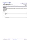
Operating Instructions <Operations and Settings> Camera Control Unit Model No. Model No. Model No. Model No. AK-HCU200P AK-HCU200PS AK-HCU200E AK-HCU200ES How the Operating Instructions are configured <Basics>: The <Basics> describes the procedure for connection with the required equipment and for installation. Before installing this unit, be sure to take the time to read through <Basics> to ensure that the unit will be installed correctly. <Operations and Settings> (this manual): This <Operations and Settings> describes how to operate the unit and how to establish its settings. ENGLISH M1012TY0 -FJ VQT4T42A (E) Contents Picture monitor (PM) displays. . . . . . . . . . . . . . . . . . . . . . . . . . . . . . . Switching the display. . . . . . . . . . . . . . . . . . . . . . . . . . . . . . . . . . . . . . Transition of displays. . . . . . . . . . . . . . . . . . . . . . . . . . . . . . . . . . . . . . Description of information displayed. . . . . . . . . . . . . . . . . . . . . . . . . . 3 3 3 4 Menu operations. . . . . . . . . . . . . . . . . . . . . . . . . . . . . . . . . . . . . . . . . . 9 Displaying and hiding the menus . . . . . . . . . . . . . . . . . . . . . . . . . . . . 9 Basic menu operations. . . . . . . . . . . . . . . . . . . . . . . . . . . . . . . . . . . . 9 Setting menu items. . . . . . . . . . . . . . . . . . . . . . . . . . . . . . . . . . . . . . . TOP MENU. . . . . . . . . . . . . . . . . . . . . . . . . . . . . . . . . . . . . . . . . . . . OPERATION menu. . . . . . . . . . . . . . . . . . . . . . . . . . . . . . . . . . . . . . MAINTENANCE Menu . . . . . . . . . . . . . . . . . . . . . . . . . . . . . . . . . . . 11 11 11 21 About trademarks and registered trademarks zz Microsoft®, Windows®, Windows® 7, and Internet Explorer® are registered trademarks or trademarks of Microsoft Corporation in the United States, Japan, and/or other countries. zz Intel® and Intel® CoreTM are trademarks or registered trademarks of Intel Corporation and its subsidiaries in the United States and/or other countries. zz Adobe® and Reader® are registered trademarks or trademarks of Adobe Systems Incorporated in the United States and/or other countries. zz SDHC logo is a trademark of SD-3C, LLC. zz Other company names and product names appearing in this manual are the registered trademarks or trademarks of their respective companies. Copyrights It is prohibited to transfer, copy, disassemble, decompile, and reverse engineer the software included with the unit, as well as export it in violation of the export laws. Web settings . . . . . . . . . . . . . . . . . . . . . . . . . . . . . . . . . . . . . . . . . . . . Menu operations. . . . . . . . . . . . . . . . . . . . . . . . . . . . . . . . . . . . . . . . Description of menus. . . . . . . . . . . . . . . . . . . . . . . . . . . . . . . . . . . . . Items when the OPERATION menu is selected . . . . . . . . . . . . . . . . Items when the MAINTENANCE menu is selected. . . . . . . . . . . . . . Table of adjustment setting ranges. . . . . . . . . . . . . . . . . . . . . . . . . . 35 Connector pin assignment table. . . . . . . . . . . . . . . . . . . . . . . . . . . . 38 Index. . . . . . . . . . . . . . . . . . . . . . . . . . . . . . . . . . . . . . . . . . . . . . . . . . . 40 Abbreviations The following abbreviations are used in this manual. zz Microsoft® Windows® 7 Professional SP1 32/64-bit is referred to as “Windows 7”. zz Microsoft® Windows® XP Professional SP3 and Microsoft® Windows® XP Home Edition SP3 are referred to as “Windows XP”. zz Windows® Internet Explorer® 8 is referred to as “Internet Explorer”. zz SD memory cards and SDHC memory cards are both referred to as “memory cards”. They are referred to individually in descriptions in which each of them is discussed separately. zz Personal computers are referred to as “computers”. zz Studio handy camera is referred to as “camera”. zz Remote operation panel is referred to as “ROP”. Furthermore, the product numbers of equipment are referred to as follows. Equipment part number AK-HC3800G AK-HC3800GS Illustrations and screen images in this manual zz Illustrations of the unit and screens may appear different from the actual unit and screens. zz The screenshots are used in accordance with the guidelines of Microsoft Corporation. 2 26 26 27 27 31 AK-HRP200G Notation in this manual AK-HC3800 AK-HRP200 AK-HCU200P AK-HCU200PS AK-HCU200E AK-HCU200ES AK-HCU200 Picture monitor (PM) displays Switching the display Display the camera statuses, warnings, and other information on the picture monitor using the operation panel of the ROP. Press the CHARA button of the ROP to display the desired information. The camera statuses, warnings, and other information are cleared when the CHARA button of the ROP is held down. CHARA button ROP: AK-HRP200 Transition of displays When trouble is detected, warning information is automatically displayed on the picture monitor. Even if status information or operation information is already displayed on the picture monitor when trouble is detected, priority is given to the display of the warning information. The descending sequence of priority for the displays on the picture monitor is as follows: WARNING displays → AUTO displays → STATUS displays → REMOTE OPERATION menu displays → CCU menu displays → OPERATION displays → no display. When the warning information with the highest priority disappears, the warning information with the next highest priority appears. Sequence of priority Higher Lower What is displayed on the screen WARNING displays ROP connected Yes No Warnings are automatically displayed when trouble is detected. zz Self-recovery The warning displays are cleared. zz Press the CHARA button of the ROP The display switches to the status screen (IRIS or status display). zz Hold down the CHARA button of the ROP The warning displays are cleared. Warnings are automatically displayed when trouble is detected. zz Self-recovery The warning displays are cleared. zz Press the SELECT dial on the unit When the transition source screen is displayed: The display switches to the transition source screen. When the transition source screen is not displayed: The warning displays are cleared. Automatically displayed AUTO displays Automatically displayed STATUS displays Perform display operations using the CHARA button of the ROP. zz Press the CHARA button of the ROP No display → (WARNING) → IRIS → status displays → Status1 → Status2 → Status3 → Status4 → Status1 ... zz Hold down the CHARA button of the ROP The status displays end. REMOTE OPERATION menu displays zz When a menu of the CCU (this unit) is displayed while the REMOTE OPERATION menu is displayed, the REMOTE OPERATION menu disappears. Display by pressing the CHARA button of the ROP. zz Operations using the SELECT dial of the ROP CCU menu displays zz When the REMOTE OPERATION menu is displayed while a menu of the CCU (this unit) is displayed, the menu of the CCU (this unit) disappears. Display by pressing the MENU button on the unit. zz Operations using the SELECT dial on the unit Display by pressing the MENU button on the unit. zz Operations using the SELECT dial on the unit OPERATION displays Automatically displayed Automatically displayed No display —— —— 3 Picture monitor (PM) displays (Continued) Description of information displayed WARNING The warning information is displayed when trouble is detected in the unit, camera, or optical fiber multi cable. The warning information items are displayed top aligned. A displayed warning information item is cleared when the status becomes normal. IRIS display When the information is not displayed on the picture monitor, display it by pressing the CHARA button of the ROP. The camera number is displayed at the top left of the screen, the IRIS level is displayed at the bottom of the screen, and the IRIS f-value is displayed at the bottom right of the screen. Set each item to be displayed on the “PM VIEW SETTING” screen that can be accessed by selecting “MAINTENANCE” on the menu. However, this screen will not appear if the menu’s “IRIS LEVEL” setting is “OFF”. - WARNING - Camera number C AM RCV LVL NG C CU RCV LVL NG C1 IRIS f-value Warning information items Display item C-- --+-----0 F4.8 Description CAM RCV LVL NG The level of the optical signal received by the camera is low. CCU RCV LVL NG The level of the optical signal received by the unit is low. CABLE OPEN The optical fiber multi cable is not connected. CABLE SHORT The optical fiber multi cable is shorted. CAM FAN NG Trouble with the cooling fan of the camera. CCU HIGH TEMP The temperature of the unit is abnormally high. CAM WARM-UP The camera is warming up. ROP SAVING DATA The data managed by the camera and this unit is being saved to the memory card in the ROP. To clear the warning information displays, press the button below. ROP (AK-HRP200): CHARA button IRIS level* *:The IRIS level is displayed based on the IRIS f-value. Status displays From the IRIS display screen, press the CHARA button of the ROP to display the statuses. The camera number, scene file number, shutter value, and extender information are displayed at the top of the screen. The ND filter value, gain value, and IRIS f-value are displayed at the bottom of the screen. Set each item to be displayed on the “PM VIEW SETTING” screen that can be accessed by selecting “MAINTENANCE” on the menu. However, when the “IRIS LEVEL” setting is “OFF”, the screen will be displayed first if the CHARA button of the ROP is pressed when the information is not displayed on the picture monitor. Camera number Scene file number C1 CAM59.94i SCENE1 EX DZ×2 EX ×2 Camera format* 1500 Shutter value CLOSE IRIS f-value Extender information 1 ND filter value 12dB Gain value *:The camera format value indicates the format of the signal output from the camera. 4 Picture monitor (PM) displays (Continued) zz Status displays (page 1 of 4) From the status display screen, press the CHARA button of the ROP to display the first page of the status displays. zz Status displays (page 2 of 4) From the status displays (page 1 of 4) screen, press the CHARA button of the ROP to display the second page. 1 / 4 -STATUS1C A M NO. M A S TER GAIN 5 6 0 0K G A M MA KNEE W H I TE CLIP B L A CK GAMMA H D DETAIL H D SKIN DETAIL M A T RIX Item Display range CAM No. MASTER GAIN 2/4 -STATUS21 0dB OFF OFF OFF OFF OFF OFF OFF OFF Remarks 1 The camera number is displayed here. │ 19 Setting values on camera The master gain value is displayed here. zz For the setting values, refer to the Operating Instructions for the camera. 5600K OFF The status of the 5600K switch is ON displayed here. OFF: 3200K, ON: 5600K GAMMA OFF The status of the gamma correction is ON displayed here. KNEE OFF The status of the knee function is ON displayed here. zz This function attenuates those parts that have exceeded the prescribed level (knee point) of the video signals to minimize saturation. WHITE CLIP OFF The status of the white clip function is ON displayed here. BLACK GAMMA OFF The status of the black gamma function ON is displayed here. zz This function changes the amplification rate of the video signals in the low-brightness areas. HD DETAIL OFF The status of the detail function for the ON HD signals is displayed here. zz This function (detail enhancer) enhances (makes sharper or softer) the detail image quality of the video output signals. HD SKIN DETAIL OFF The status of the skin tone detail ON function for the HD signals is displayed here. zz This function minimizes or emphasizes the detail components applied to the skin tone. MATRIX OFF The status of the matrix function is ON displayed here. zz This function compensates the saturation and hue. SHUTTER ND FILTER LENS EXTENDER AUTO IRIS SCENE FILE SD DETAIL ASU REF ASU MODE Item SHUTTER ND FILTER LENS EXTENDER AUTO IRIS SCENE FILE SD DETAIL ASU REF ASU MODE OFF 1 1.0 OFF SCENE1 OFF USER1 OUT FULL Display range Setting values on camera Remarks The speed of the electronic shutter is displayed here. zz For the setting values, refer to the Operating Instructions for the camera. 1 The names of the ND filters are │ displayed here. 4 The names (each consisting of 4 characters) correspond to filter 1, 2, 3 and 4. zz Displayed as the filter names are the names that were set using the unit’s menu. 1.0 The magnification of the lens extender 2.0 is displayed here. OFF The status of the auto IRIS function is ON displayed here. SCENE1 The selected scene file is displayed │ here. SCENE4 OFF OFF The status of the detail function for the ON SD signals is displayed here. USER1 The reference file used during auto USER2 setup is displayed here. USER3 FACTORY OUT FULL The auto setup mode is displayed here. OUT EASY 5 Picture monitor (PM) displays (Continued) zz Status displays (page 3 of 4) From the status displays (page 2 of 4) screen, press the CHARA button of the ROP to display the third page. zz Status displays (page 4 of 4) From the status displays (page 3 of 4) screen, press the CHARA button of the ROP to display the fourth page. 3 / 4 - S T A TUS3D O W N C O N V ERT MODE U P C O N V E R T MODE RETURN1 RETURN2 RETURN3 RETURN4 S D I R E T U RN1 S D I R E T U RN2 S D I O U T P UT1&2 S D I O U T P UT3&4 N O R M AL/PM COMPOSITE N O R M AL/PM Item Display range 4/4 -STATUS4SC SC HD SDI1 HD SDI2 HD SDI1 HD SDI2 HD HD HD HD NORMAL Remarks SC The setting information of the downSQ conversion system is displayed here. LB UPCONVERT MODE SC The setting information of the SQ up-conversion system is displayed here. LB RETURN1 RETURN3 RETURN4 HD SDI1 The statuses of the input format HD SDI2 allocations for SDI return signals 1 to 4 SD SDI1 are displayed here. SD SDI2 VBS SDI RETURN1 HD The format of the return signal to be SD input to [HD/SD SDI 1] of the RETURN IN connectors is displayed here. SDI RETURN2 HD The format of the return signal to be SD input to [HD/SD SDI 2] of the RETURN IN connectors is displayed here. SDI OUTPUT1&2 HD The format of the signals to be output SD from [1] and [2] of the HD/SD SDI OUT connectors is displayed here. SDI OUTPUT3&4 HD The format of the signals to be output SD from [3/PM] and [4/PM] of the HD/SD SDI OUT connectors is displayed here. SDI OUTPUT3&4 NORMAL/PM NORMAL The setting information for output from PM [3/PM] and [4/PM] of the HD/SD SDI OUT connectors is displayed here. COMPOSITE NORMAL/PM NORMAL The signal to be output from [OUT/PM] PM of the VBS connectors is displayed here. 6 H CABLE OPEN CABLE SHORT CAM RECEIVE LEVEL CCU RECEIVE LEVEL VERSION 1.00-00-0.00 PM DOWNCONVERT MODE RETURN2 HOURS CCU Item Display range Remarks HOURS CCU —— The unit’s cumulative operation time is displayed here. CABLE OPEN —— This item flashes when the optical fiber multi cable is not connected. CABLE SHORT —— This item flashes when the optical fiber multi cable is short-circuited. CAM RECEIVE LEVEL The level of the optical signals received │ by the camera is displayed in 5 gradations. CCU RECEIVE LEVEL The level of the optical signals received │ by the unit is displayed in 5 gradations. VERSION —— The unit’s software version is displayed here. Picture monitor (PM) displays (Continued) zz Operation displays (manual) The operation displays appear at the bottom of the screen for 4 seconds when any of the following operations have been performed with the operation panel of the ROP. zz“MASTER GAIN” is changed zz“SHUTTER” is changed zz“LENS EXT” is changed zz“FILTER” is changed zz“SCENE FILE” is changed zz“REF LOAD” is changed The display time can be changed from “MAINTENANCE” menu → “PM OPERATION STATUS” → “STATUS DISP TIME”. zz Operation displays (AUTO) If the AWB function, ABB function, or AUTO SETUP function has been activated when a menu is not displayed on the picture monitor, information on the operation performed appears at the bottom of the screen. When the AUTO SETUP operations are displayed, they will remain displayed until the operations are completed. The display is cleared 4 seconds after the operations are completed. If the operations cannot be completed, they will remain displayed until the NG (error) items of the AUTO function are released. The display time can be changed from “MAINTENANCE” menu → “PM OPERATION STATUS” → “STATUS DISP TIME”. AUTO SETUP: ACTIVE GAMMA OPERATION FILTER FIL1 Item MASTER GAIN SHUTTER LENS EXT FILTER SCENE FILE REF LOAD Display range Setting values on camera Setting values on camera Remarks The master gain value is displayed here. (in 3 dB increments) zz For the setting values, refer to the Operating Instructions for the camera. The speed of the electronic shutter is displayed here. zz For the setting values, refer to the Operating Instructions for the camera. 1.0 The magnification of the lens extender 2.0 is displayed here. zz When the magnification of the lens extender is set to 2×, “2.0” is displayed. Otherwise, “1.0” is displayed. 4 characters The name of the ND filter is displayed here. SCENE1 This indicates the scene file name. │ SCENE4 OFF FACTORY This indicates the reference file that was USER1 loaded using the SCENE command. USER2 USER3 Item ABB START Display description: Appears on two lines at the bottom of the screen. Top line: status Bottom line: Detailed information ABB: ACTIVE (None) AWB START AWB: ACTIVE (None) AUTO OK (Common to ABB, AWB, and AUTO SETUP) ABB: OK AUTO NG1*1 (Only for ABB and AWB) ABB: NG AUTO SETUP START*2 AUTO SETUP: ACTIVE AUTO NG2*3 (Only for AUTO SETUP) AUTO SETUP: NG AUTO BREAK (Common to ABB, AWB and AUTO SETUP) ABB: BREAK AUTO READY (Only for AUTO SETUP) AUTO SETUP: READY AWB: OK AUTO SETUP: OK (None) AWB: NG Detailed information of the NG (error) message is displayed here*1. Detailed information is displayed here*2. Detailed information of the NG (error) message is displayed here*3. AWB: BREAK AUTO SETUP: BREAK (None) (None) 7 Picture monitor (PM) displays (Continued) *1: [AUTO NG1 detailed information] The AUTO NG1 detailed information is displayed flashing on the screen. Rch OUT RANGE Gch OUT RANGE Bch OUT RANGE AWB LOW LIGHT AWB HIGH LIGHT zz Contrast automatic adjustment display This appears when contrast automatic adjustment (DRS SWITCH) is set to ON by ROP operation. <DRS ON> *2: [AUTO SETUP operation information] The AUTO SETUP operation information is displayed on the screen. B.SHD OPERATION FLARE OPERATION ABB OPERATION AWB OPERATION *3: [AUTO NG2 detailed information] The AUTO NG2 detailed information is displayed flashing on the screen. ABB Gch OUT RANGE ABB Bch OUT RANGE ABB Rch OUT RANGE B.SHD Gch OUT RANGE B.SHD Bch OUT RANGE B.SHD Rch OUT RANGE FLARE Gch OUT RANGE FLARE Bch OUT RANGE FLARE Rch OUT RANGE AWB Gch OUT RANGE AWB Bch OUT RANGE AWB Rch OUT RANGE NOT RUNNING ILLEGAL MODE(CINEGAMMA) NOT RUNNING ILLEGAL MODE(D.EXT) NOT RUNNING ILLEGAL MODE(SCANREVERSE) NOT RUNNING ILLEGAL MODE(BAR) NOT RUNNING ILLEGAL MODE(TESTSAW) 8 zz For details on contrast automatic adjustment, refer to the Operating Instructions for the ROP. Menu operations While viewing the menu screen of the picture monitor, operate the MENU button and SELECT dial on the front panel. MENU button Basic menu operations Selecting a menu 1. Press the SELECT dial SELECT dial Displaying and hiding the menus 1. Hold down the MENU button The menu screen appears and the MENU button lights. “TOP MENU” appears first. zzIf the MENU button is held down when the menu is displayed, the menu closes and the MENU button turns off. Move the cursor to the desired item (OPERATION or MAINTENANCE) on the “TOP MENU” screen, and then press the SELECT dial to display the menu screen one level below the selected item. zzWhen the SELECT dial is turned clockwise, the cursor moves down; conversely, when it is turned counterclockwise, the cursor moves up. TOP MENU OPERATION MAINTENANCE 2. Turn the SELECT dial to move the cursor to the menu item you want to set, and then press the SELECT dial. OPERATION SETTING1 SETTING2 HD/SD PHASE BAR ID INCOM/MIC Hold down the MENU button Hold down the MENU button The setting screen one level below the selected menu item appears. T OP MENU O P E RATION M A I NTENANCE SETTING1 CCU MODE SDI SDI SDI SDI RETURN1 RETURN2 OUTPUT1&2 OUTPUT3&4 NORMAL/PM COMPOSITE NORMAL/PM 1080/59.94i HD HD HD HD PM PM zzMoving the cursor to the menu title and then pressing the SELECT dial redisplays “TOP MENU”. TOP MENU OPERATION MAINTENANCE 9 Menu operations (Continued) Changing the setting value of a setting item Menu items with multiple setting items on one line and text input menu items A number of items and the set values are displayed on the setting screen at the lowest level. 1. Turn the SELECT dial to move the cursor to the menu item you want to set, and then press the SELECT dial. The setting value of the selected menu item starts flashing and you can change it. 1. Turn the SELECT dial to move the cursor to the menu item you want to set, and then press the SELECT dial. The cursor becomes “” and you can use the SELECT dial to move the cursor to a setting item in the selected menu item. BAR ID S E T T ING1 CCU MODE SDI SDI SDI SDI R E T U RN1 R E T U RN2 O U T P UT1&2 O U T P UT3&4 N O R M AL/PM COMPOSITE N O R M AL/PM 1080/59.94i HD HD HD HD PM BAR ID SWITCH BRIGHTNESS ID1 POSITION V:00 ID1 OFF 100% H:00 ## ID2 POSITION V:01 H:00 PM 2. Turn the SELECT dial to move the cursor to the item you want to set, and then press the SELECT dial. 2. Turn the SELECT dial to change the value, and then press the SELECT dial. The setting value of the selected item starts flashing and you can change it. Turning the SELECT dial changes the setting value and pressing the SELECT dial confirms the setting value. BAR ID SWITCH BRIGHTNESS ID1 POSITION S E T T ING1 CCU MODE SDI SDI SDI SDI R E T U RN1 R E T U RN2 O U T P UT1&2 O U T P UT3&4 N O R M AL/PM COMPOSITE N O R M AL/PM BAR ID 1080/59.94i SD HD HD HD PM PM Once the setting value has been confirmed, the flashing stops, and the cursor can be moved from one menu to another. In some cases, the setting is reflected when the setting value is changed in the flashing state; in other cases, it is reflected when the SELECT dial is pressed to confirm the setting value. V:00 ID1 OFF 100% H:00 ## ID2 POSITION V:01 H:00 3. Turn the SELECT dial to change the value, and then press the SELECT dial. Turning the SELECT dial changes the setting value (or characters), and pressing the SELECT dial confirms the setting value (or characters). BAR ID BAR ID SWITCH BRIGHTNESS ID1 POSITION V:02 ID1 OFF 100% H:00 ## ID2 POSITION V:01 H:00 When the setting value is confirmed and the flashing stops, you can move the cursor. If you press the SELECT dial while the cursor is on the left of a menu item, the cursor becomes “” and you can select the menu item. BAR ID BAR ID SWITCH BRIGHTNESS ID1 POSITION V:02 ID1 ID2 POSITION 10 OFF 100% H:03 ## V:01 H:00 Setting menu items zz SETTING1 Screen TOP MENU This is the first screen displayed when you hold down the MENU button. Select one of the menus. This is the selection screen for the SETTING1 menu. Moving the cursor to the “SETTING1” menu title and then pressing the SELECT dial redisplays the OPERATION menu one level up. SETTING1 T OP MENU CCU MODE O P E RATION M A I NTENANCE zz OPERATION Select this to open the OPERATION menu screen. zz MAINTENANCE Select this to open the MAINTENANCE menu screen. SDI SDI SDI SDI RETURN1 RETURN2 OUTPUT1&2 OUTPUT3&4 NORMAL/PM COMPOSITE NORMAL/PM Item CCU MODE zz SETTING1 Select this to display the SETTING1 screen. zz SETTING2 Select this to display the SETTING2 screen. zz HD/SD PHASE Select this to display the HD/SD PHASE screen. zz BAR ID Select this to display the BAR ID screen. zz INCOM/MIC Select this to display the INCOM/MIC screen. PM Setting value Remarks 59.94 Hz: Set the format of the signal to be output 1080/59.94i from the unit. 1080/50i 50 Hz: 1080/59.94i 1080/50i SDI RETURN1 HD Set the format of the return signal to be SD input to [HD/SD SDI 1] of the RETURN IN connectors. SDI RETURN2 HD Set the format of the return signal to be SD input to [HD/SD SDI 2] of the RETURN IN connectors. SDI OUTPUT1&2 HD Set the format of the signals to be SD output from [1] and [2] of the HD/SD SDI OUT connectors. SDI OUTPUT3&4 HD Set the format of the signals to be SD output from [3/PM] and [4/PM] of the HD/SD SDI OUT connectors. OPERATION S E T TING1 S E T TING2 H D / SD PHASE B A R ID I N C OM/MIC HD HD HD HD PM indicates the factory default setting. OPERATION menu This is the selection screen for the OPERATION menu. Moving the cursor to the “OPERATION” menu title and then pressing the SELECT dial redisplays “TOP MENU”. 1080/59.94i SDI OUTPUT3&4 NORMAL/PM NORMAL Set the signal to be output from [3/PM] PM and [4/PM] of the HD/SD SDI OUT connectors. NORMAL: Output the main line images. PM: Output the picture monitor images. COMPOSITE NORMAL/PM NORMAL Set the signal to be output from PM [OUT/PM] of the VBS connectors. NORMAL: Output the main line images. PM: Output the picture monitor images. zz When the SDI OUTPUT3&4 NORMAL/PM item and COMPOSITE NORMAL/PM item are set to “NORMAL”, the menus and statuses will not be able to be displayed because the picture monitor images will not be output. When one of items is set to “NORMAL”, the other one is set to “PM” as both of the items cannot be set to “NORMAL”. 11 Setting menu items (Continued) zz SETTING2 Screen This is the selection screen for the SETTING2 menu. Moving the cursor to the “SETTING2” menu title and then pressing the SELECT dial redisplays the OPERATION menu one level up. Item BAR LPF Select the filter through which to pass the color bar signals to be output from the HD/SD SDI OUT connectors when BAR has been selected on the operation panel of the ROP. zz A higher TAP value will ensure a smooth rise and fall of the waveforms and reduce both the overshoot and undershoot. BAR USER1 75%WHITE 100%WHITE +I_SIGNAL –I_SIGNAL Set user range 1 for when ARIB has been selected as the HD BAR SELECT setting. This can be set when “ARIB” is selected for the HD BAR SELECT item. In the case of another setting, “——” is displayed and a setting cannot be selected. BAR USER2 0%BLACK Set user range 2 for when ARIB has +Q_SIGNAL been selected as the HD BAR SELECT setting. This can be set when “ARIB” is selected for the HD BAR SELECT item. In the case of another setting, “——” is displayed and a setting cannot be selected. SETUP 7.5% ON Select whether to add the setup 7.5 % OFF level to the SD signals to be output from [OUT/PM] of the VBS connectors. PATHO ON Select ON/OFF for the pathological OFF signals. NORMAL H D B A R S ELECT B A R L PF B A R U SER1 B A R U SER2 S E T U P 7 . 5% PATHO ARIB 7TAP 75%WHITE 0%BLACK OFF OFF indicates the factory default setting. Item FS DELAY HD BAR SELECT 12 Setting value Remarks NORMAL Select the delay mode for the HD return SHORT signals. NORMAL: Matches return signal input that does not match the sync phase to the phase of the camera by delaying it by 1 frame. SHORT: Sets the shortest delay. (5 H) However, if the following conditions are not met, it is delayed by 1 frame + 5H. zz HD signal zz The SD-HD V item in the HD/SD PHASE screen is “ADVANCE” or “0H_SD_DLAY” zz When output from this unit is used as the return signal, the delay is less than 3H FULL BARS-1 ARIB BARS-2 BARS-3 BARS-4 BARS-5 BARS-6 Select the color bar signals to be output from the HD/SD SDI OUT connectors and VBS connector when “BAR” has been selected on the operation panel of the ROP. When they are output in VBS or SD format, color bars in HD format are output in the mode specified with DOWNCONVERT MODE*. FULL: 75 % full field color bar BARS-1: Color bar based on the SMPTE standard ARIB: ARIB multi-format color bar BARS-2: Color bar based on the EIAJ standard BARS-3: Split field color bar BARS-4: 75 % full field color bar placed in an area with a 4:3 aspect ratio. (Displayed 40 % gray outside the area.) BARS-5: Color bar based on the SMPTE standard that is placed in an area with a 4:3 aspect ratio. (Displayed 40 % gray outside the area.) BARS-6: Color bar based on the EIAJ standard that is placed in an area with a 4:3 aspect ratio. (Displayed 40 % gray outside the area.) Remarks OFF 3TAP 5TAP 7TAP 9TAP S E T T ING2 FS DELAY Setting value *:The DOWNCONVERT MODE setting can be configured by operating the REMOTE OPERATION menu with the ROP. For details, refer to Operating Instructions <Operations and Settings> of AK-HRP200. Setting menu items (Continued) zz HD/SD PHASE Screen This menu is used for the HD signal and SD signal phase adjustments. Moving the cursor to the “HD/SD PHASE” menu title and then pressing the SELECT dial redisplays the OPERATION menu one level up. HD/SD PHASE H D H PHASE S D H PHASE S D - HD V 0 0 0H indicates the factory default setting. Item HD H PHASE Setting value 59.94 Hz: Adjust the horizontal sync phase of –1099 HDTV output in respect to the sync │ signals of the system. 0 │ 1099 50 Hz: SD H PHASE –1319 │ 0 │ 1319 59.94 Hz: Adjust the horizontal sync phase of –857 SDTV output in respect to the sync │ signals of the system. 0 │ 857 50 Hz: SD-HD V Remarks –863 │ 0 │ 863 0H Set the vertical phase of the HDTV ADVANCE output in relation to the SDTV output. 0H_SD_DLAY 0H: Sets the vertical phase to the same phase. ADVANCE: When the field frequency is 59.94 Hz, the phase advance is 90H. When the field frequency is 50 Hz, the phase advance is 75H. 0H_SD_DLAY: The SDTV signals are delayed and set in-phase with the HDTV signals. zz When the setting of this item is set to “0H” or “ADVANCE” while the field frequency is 50 Hz, images in SD format are delayed by 1 frame + 75 lines only when letterbox is selected for DOWNCONVERT MODE*. For the relationship with the sync phase, refer to pages 14 to 19. *:The DOWNCONVERT MODE setting can be configured by operating the REMOTE OPERATION menu with the ROP. For details, refer to Operating Instructions <Operations and Settings> of AK-HRP200. 13 Setting menu items (Continued) zz SD signal phase <1080i/59.94 Hz format> Setting of SD-HD V item: 0H GEN LOCK zz 3.58 BB signal (525/59.94/I) Black burst signal 2 3 4 5 6 3 4 5 6 zz VBS/SDI (SD) signal (525/59.94/I) CCU_VBS/SDI (SD)_OUT 2 CAM_HD_SDI_OUT zz HD_SDI signal (1125/59.94/I) 1122 1123 1124 1125 1 2 3 4 5 6 7 CCU_HD_SDI_OUT zz HD_SDI signal (1125/59.94/I) 1122 1123 1124 1125 1 2 3 4 5 6 7 90H (HD) LINE Setting of SD-HD V item: ADVANCE (90H) GEN LOCK zz 3.58 BB signal (525/59.94/I) Black burst signal 2 4 5 6 3 4 5 6 zz VBS/SDI (SD) signal (525/59.94/I) CCU_VBS/SDI (SD)_OUT 2 CAM_HD_SDI_OUT zz HD_SDI signal (1125/59.94/I) 1122 1123 1124 1125 1 2 3 4 5 6 7 1122 1123 1124 1125 1 2 3 4 5 6 7 CCU_HD_SDI_OUT zz HD_SDI signal (1125/59.94/I) 90H (HD) LINE 14 3 Setting menu items (Continued) Setting of SD-HD V item: 0H_SD_DLAY (1FRAM–90H DLY) GEN LOCK zz 3.58 BB signal (525/59.94/I) Black burst signal 2 3 4 5 6 3 4 5 6 zz VBS/SDI (SD) signal (525/59.94/I) CCU_VBS/SDI (SD)_OUT 2 1FRAM–90H (HD) LINE CAM_HD_SDI_OUT zz HD_SDI signal (1125/59.94/I) 1122 1123 1124 1125 1 2 3 4 5 6 7 1 2 3 4 5 6 7 CCU_HD_SDI_OUT zz HD_SDI signal (1125/59.94/I) 1122 1123 1124 1125 <1080i/50 Hz format> Setting of SD-HD V item: 0H GEN LOCK zz 4.43 BB signal (626/50/I) Black burst signal 624 625 1 2 3 4 625 1 2 3 4 zz VBS/SDI (SD) signal (626/50/I) CCU_VBS/SDI (SD)_OUT 624 CAM_HD_SDI_OUT zz HD_SDI signal (1125/50/I) 1122 1123 1124 1125 1 2 3 4 5 6 7 CCU_HD_SDI_OUT zz HD_SDI signal (1125/50/I) 1122 1123 1124 1125 1 2 3 4 5 6 7 75H (HD) LINE 15 Setting menu items (Continued) Setting of SD-HD V item: ADVANCE (75H) GEN LOCK zz 4.43 BB signal (626/50/I) Black burst signal 624 625 1 2 3 4 624 625 1 2 3 4 624 625 1 2 3 4 625 1 2 3 4 zz VBS/SDI (SD) signal (626/50/I) CCU_VBS/SDI (SD)_OUT CAM_HD_SDI_OUT zz HD_SDI signal (1125/50/I) 1122 1123 1124 1125 1 2 3 4 5 6 7 1122 1123 1124 1125 1 2 3 4 5 6 7 CCU_HD_SDI_OUT zz HD_SDI signal (1125/50/I) 75H (HD) LINE Setting of SD-HD V item: 0H_SD_DLAY (1FRAM–75H DLY) GEN LOCK Black burst signal CCU_VBS/SDI (SD)_OUT zz 4.43 BB signal (626/50/I) zz VBS/SDI (SD) signal (626/50/I) 624 1FRAM–75H (HD) LINE CAM_HD_SDI_OUT zz HD_SDI signal (1125/50/I) 1122 1123 1124 1125 1 2 3 4 5 6 7 1 2 3 4 5 6 7 CCU_HD_SDI_OUT zz HD_SDI signal (1125/50/I) 1122 1123 1124 1125 16 Setting menu items (Continued) zz HD signal phase <1080i/59.94 Hz format> Setting of SD-HD V item: 0H GEN LOCK zz Tri-level sync signal (1125/59.94/I) Tri-level sync signal 1122 1123 1124 1125 1 2 3 4 5 6 7 1 2 3 4 5 6 7 CAM_HD_SDI_OUT zz HD_SDI signal 1122 1123 1124 1125 1 2 3 4 5 6 7 CCU_HD_SDI_OUT zz HD_SDI signal (1125/59.94/I) 1122 1123 1124 1125 zz VBS/SDI (SD) signal (525/59.94/I) CCU_VBS/SDI (SD)_OUT 2 3 4 5 6 3 4 5 6 90H (HD) LINE Setting of SD-HD V item: ADVANCE (90H) GEN LOCK Tri-level sync signal zz Tri-level sync signal (1125/59.94/I) 1122 1123 1124 1125 1 2 3 4 5 6 7 1122 1123 1124 1125 1 2 3 4 5 6 7 1122 1123 1124 1125 1 2 3 4 5 6 7 CCU_HD_SDI_OUT zz HD_SDI signal CAM_HD_SDI_OUT zz HD_SDI signal (1125/59.94/I) CCU_VBS/SDI (SD)_OUT zz VBS/SDI (SD) signal (525/59.94/I) 2 90H (HD) LINE 17 Setting menu items (Continued) Setting of SD-HD V item: 0H_SD_DLAY (1FRAM–90H DLY) GEN LOCK Tri-level sync signal zz Tri-level sync signal (1125/59.94/I) 1122 1123 1124 1125 1 2 3 4 5 6 7 1 2 3 4 5 6 7 1 2 3 4 5 6 7 CCU_HD_SDI_OUT zz HD_SDI signal 1122 1123 1124 1125 CAM_HD_SDI_OUT zz HD_SDI signal (1125/59.94/I) 1122 1123 1124 1125 CCU_VBS/SDI (SD)_OUT zz VBS/SDI (SD) signal (525/59.94/I) 2 3 4 5 6 1FRAM–90H (HD) LINE <1080i/50 Hz format> Setting of SD-HD V item: 0H GEN LOCK zz Tri-level sync signal (1125/50/I) Tri-level sync signal 1122 1123 1124 1125 1 2 3 4 5 6 7 1 2 3 4 5 6 7 CAM_HD_SDI_OUT zz HD_SDI signal (1125/50/I) 1122 1123 1124 1125 1 2 3 4 5 6 7 CCU_HD_SDI_OUT zz HD_SDI signal (1125/50/I) 1122 1123 1124 1125 CCU_VBS/SDI (SD)_OUT zz VBS/SDI (SD) signal (626/50/I) 624 75H (HD) LINE 18 625 1 2 3 4 Setting menu items (Continued) Setting of SD-HD V item: ADVANCE (75H) GEN LOCK Tri-level sync signal zz Tri-level sync signal (1125/50/I) 1122 1123 1124 1125 1 2 3 4 5 6 7 1122 1123 1124 1125 1 2 3 4 5 6 7 1122 1123 1124 1125 1 2 3 4 5 6 7 CCU_HD_SDI_OUT zz HD_SDI signal (1125/50/I) CAM_HD_SDI_OUT zz HD_SDI signal (1125/50/I) CCU_VBS/SDI (SD)_OUT zz VBS/SDI (SD) signal (626/50/I) 624 625 1 2 3 4 75H (HD) LINE Setting of SD-HD V item: 0H_SD_DLAY (1FRAM–75H DLY) GEN LOCK Tri-level sync signal zz Tri-level sync signal (1125/50/I) 1122 1123 1124 1125 1 2 3 4 5 6 7 1 2 3 4 5 6 7 1 2 3 4 5 6 7 CCU_HD_SDI_OUT zz HD_SDI signal (1125/50/I) 1122 1123 1124 1125 CAM_HD_SDI_OUT zz HD_SDI signal (1125/50/I) 1122 1123 1124 1125 CCU_VBS/SDI (SD)_OUT zz VBS/SDI (SD) signal (626/50/I) 624 625 1 2 3 4 1FRAM–75H (HD) LINE 19 Setting menu items (Continued) zz BAR ID Screen This menu is used to set the BAR IDs displayed on the color bars. Moving the cursor to the “BAR ID” menu title and then pressing the SELECT dial redisplays the OPERATION menu one level up. Item ID2 POSITION B A R ID B A R I D S WITCH B R I G H T N E SS I D 1 P O S I TION ID1 V:00 OFF 100% H:00 V:01 H:00 V:00 H:00 ## I D 2 P O S I TION ID2 OFFSET ## indicates the factory default setting. Item BAR ID SWITCH BRIGHTNESS ID1 POSITION ID1 Setting value ID2 Remarks ON Set the display of the BAR IDs OFF displayed on the color bars when the color bars are displayed to ON or OFF. V (vertical): 00 01 │ 05 H (horizontal): 00 │ 15 V (vertical): 00 │ 05 H (horizontal): 00 │ 15 Set the display start position of BAR ID1 displayed on the color bars when the color bars are displayed. Set from which character in the vertical direction and which character in the horizontal direction, starting from the top left of the color bar, to start displaying the BAR ID using the font size as the reference. zz When the coordinates of ID1 and ID2 are the same, bar ID1’s character string will be placed on top of bar ID2 (BAR ID2 will be below). When the vertical coordinates are the same and the horizontal coordinates differ, the BAR ID with the horizontal coordinates set later will be placed on top of the vertical one. ##□□□□□□□□□□□□□□ Set the character string of BAR ID1. The ID that is set here is displayed on the color bar. Up to 16 characters can be set. zz When “##” has been input in the character string, this part is replaced by the camera number (1 to 19) and displayed. Remarks Set the display start position of BAR ID2 displayed on the color bars when the color bars are displayed. Set from which character in the vertical direction and which character in the horizontal direction, starting from the top left of the color bar, to start displaying the BAR ID using the font size as the reference. zz When the coordinates of ID1 and ID2 are the same, bar ID1’s character string will be placed on top of bar ID2 (BAR ID2 will be below). When the vertical coordinates are the same and the horizontal coordinates differ, the BAR ID with the horizontal coordinates set later will be placed on top of the vertical one. ##□□□□□□□□□□□□□□ Set the character string of BAR ID2. The ID that is set here is displayed on the color bar. Up to 16 characters can be set. Characters which can be used: zz Alphanumeric characters zz Spaces zz !"#%&'()+,-./:;<= ` >?@[]_~ 0% Set the character color, in units of 10 │ %, of the BAR ID displayed on the color 100% bar when the color bar is displayed. 0%: (black), 100%: (white) Characters which can be used: zz Alphanumeric characters zz Spaces zz !"#%&'()+,-./:;<= ` >?@[]_~ 20 Setting value zz When “##” has been input in the character string, this part is replaced by the camera number (1 to 19) and displayed. OFFSET V (vertical): 00 │ 79 H (horizontal): 00 │ 89 The display positions of the bar IDs can be finely adjusted within the font size range. Using the top left of the font as the origin point, set the horizontal offset and vertical offset. Setting menu items (Continued) zz INCOM/MIC Screen This menu is used for the unit’s intercom settings. Configure the camera’s intercom setting on the camera. Moving the cursor to the “INCOM/MIC” menu title and then pressing the SELECT dial redisplays the OPERATION menu one level up. MAINTENANCE Menu This is the selection screen for the MAINTENANCE menu. Moving the cursor to the “MAINTENANCE” menu title and then pressing the SELECT dial redisplays “TOP MENU”. INCOM/MIC 4 W / RTS IN LEVEL 4 W / RTS OUT LEVEL R T S CANCEL G A I N PGM M I C 1 LEVEL M I C 2 LEVEL C M / DM C C U INCOM MIC C C U SIDE TONE 0dB 0dB 0dB 0dB 0dB 0dB DM 0dB –6dB indicates the factory default setting. Item 4W/RTS IN LEVEL Setting value Remarks –40.0dB Set the input level for the intercom │ (4-WIRE and RTS) signal. 0dB (0.5dB increments) │ 20.0dB 4W/RTS OUT LEVEL –40.0dB Set the output level for the intercom │ (4-WIRE and RTS) signal. 0dB (0.5dB increments) │ 20.0dB RTS CANCEL –40.0dB Set the noise canceling level for the │ engineering intercom (RTS system). 31.5dB (0.5dB increments) GAIN PGM 0dB Set the gain for the PGM sound. 20dB MIC1 LEVEL –40.0dB Finely adjust the level of output from the │ MIC OUT 1 connector. 0dB (0.5dB increments) │ 20.0dB MIC2 LEVEL –40.0dB Finely adjust the level of output from the │ MIC OUT 2 connector. 0dB (0.5dB increments) │ 20.0dB CM/DM MAINTENANCE START UP ANALOG GAIN ND NAME NETWORK VERSION PM VIEW SETTING PM OPERATION STATUS SYSTEM SD CARD zz START UP Displays the screen for setting the control to be performed when the unit’s power has been turned on. zz ANALOG GAIN Displays the screen for setting the analog signal levels. zz ND NAME Displays the screen for setting the ND filter names. zz NETWORK Displays the network setting screen. zz VERSION Displays the version information screen. zz PM VIEW SETTING Displays the screen for setting ON or OFF for the items (IRIS and status displays) to display on the picture monitor. zz PM OPERATION STATUS Displays the screen for setting ON or OFF for the operation items to display on the picture monitor. zz SYSTEM Displays the screen for initializing the menu settings. zz SD CARD Displays the screen for setting the saving of data and upgrading of software using a memory card. CM Use this to select the type of intercom DM microphone (carbon microphone or dynamic microphone) to be connected to the unit. CM: Carbon microphone DM: Dynamic microphone CCU INCOM MIC –40.0dB Use this to set the level of the unit’s │ intercom microphones for regular use. 0dB (0.5dB increments) │ 12.0dB CCU SIDE TONE –40.0dB Use this to set the side tone level of the │ unit’s intercom for regular use. –6dB (0.5dB increments) │ 0.0dB 21 Setting menu items (Continued) zz START UP Screen This menu is used to set the control that is performed when the unit’s power is turned on. Moving the cursor to the “START UP” menu title and then pressing the SELECT dial redisplays the MAINTENANCE menu one level up. zz ANALOG GAIN Screen This menu is used to set the analog signal levels. Moving the cursor to the “ANALOG GAIN” menu title and then pressing the SELECT dial redisplays the MAINTENANCE menu one level up. ANALOG GAIN S T A R T UP CAM POWER VF POWER COMPOSITE Item indicates the factory default setting. Item CAM POWER VF POWER Setting value –50 REMOTE REMOTE Remarks OFF Set the control of the camera’s power ON that is to be performed when the unit’s REMOTE power is turned on. OFF: The camera’s power will not come on even when the unit’s power is turned on. In this case, “HEAD POWER” must be set to ON on the operation panel of the ROP. ON: The camera’s power will come on when the unit’s power is turned on. REMOTE: Starts up in accordance with the “HEAD POWER” state that was set with the ROP last time. OFF Set the control of the viewfinder’s power ON that is performed when the unit’s power REMOTE is turned on. OFF: The viewfinder’s power will not come on even when the unit’s power is turned on. In this case, “VF POWER” must be set to ON on the operation panel of the ROP. ON: When the viewfinder’s POWER switch is ON, turning on the power of this unit also turns on the power of the viewfinder. REMOTE: Starts up in accordance with the “VF POWER” state that was set with the ROP last time. Setting value COMPOSITE Remarks –50 Set the video level of the analog │ composite signal to be output from 50 [OUT/PM] of the VBS connectors. (Variable range: ±8 IRE or more is possible) zz ND NAME Screen This menu is used to set the names of the ND filters. The names set here are displayed for the statuses on the picture monitor. Names consisting of up to 4 characters can be set for ND FILTER1 NAME to ND FILTER4 NAME. Moving the cursor to the “ND NAME” menu title and then pressing the SELECT dial redisplays the MAINTENANCE menu one level up. ND NAME Item ND FILTER1 NAME 1 ND FILTER2 NAME 2 ND FILTER3 NAME 3 ND FILTER4 NAME 4 Setting value Remarks ND FILTER1 NAME Max. 4 characters Set the name of ND filter 1. ND FILTER2 NAME Max. 4 characters Set the name of ND filter 2. ND FILTER3 NAME Max. 4 characters Set the name of ND filter 3. ND FILTER4 NAME Max. 4 characters Set the name of ND filter 4. Characters which can be used: zz Alphanumeric characters zz Spaces zz !"#%&'()+,-./:;<=>?@[]_~ ` 22 Setting menu items (Continued) zz NETWORK Screen This menu is used for the network settings. Moving the cursor to the “NETWORK” menu title and then pressing the SELECT dial redisplays the MAINTENANCE menu one level up. zz VERSION Screen This menu is used to display the version information for the application software and FPGA. Moving the cursor to the “VERSION” menu title and then pressing the SELECT dial redisplays the MAINTENANCE menu one level up. NETWORK VERSION I P ADDRESS 192.168.0.20 S U B NET MASK D E F AULT GATEWAY 255.255.255.0 192.168.0.1 80 PORT M A C ADDRESS - SOFTWARE HARDWARE FPGA1 HARDWARE FPGA2 HARDWARE FPGA3 - - - 0.00-00-0.00 0.00-00-0.00 0.00-00-0.00 0.00-00-0.00 - indicates the factory default setting. Item IP ADDRESS SUBNET MASK DEFAULT GATEWAY PORT MAC ADDRESS Setting value Remarks 192.168.0.20 Set the IP address. zz Select each set of three digits with the cursor. 255.255.255.0 Set the subnet mask. 255.255.255.128 255.255.255.192 255.255.255.224 255.255.255.240 255.255.255.248 255.255.255.252 255.255.255.254 255.255.255.255 Item SOFTWARE Remarks Displays the version of the software installed on the unit. HARDWARE FPGA1 HARDWARE FPGA2 Displays the versions of the programs installed on the unit. HARDWARE FPGA3 192.168.0.1 Set the default gateway. 1 Set the port number. │ 80 │ 65535 —— Displays the MAC address. 23 Setting menu items (Continued) zz PM VIEW SETTING Screen This menu is used to set ON or OFF for the items (IRIS, status display) to display on the picture monitor. Moving the cursor to the “PM VIEW SETTING” menu title and then pressing the SELECT dial redisplays the MAINTENANCE menu one level up. zz PM OPERATION STATUS Screen This menu is used to set ON or OFF for the operation items to display on the picture monitor. Moving the cursor to the “PM OPERATION STATUS” menu title and then pressing the SELECT dial redisplays the MAINTENANCE menu one level up. P M V IEW SETTING C A M E R A N O. CAM MOD S C E N E F I LE NO. SHUTTER ND FILTER GAIN E X T E N D E R INFO IRIS I R I S L E V EL PM OPERATION STATUS ON ON ON ON ON ON ON ON ON indicates the factory default setting. Item Setting value 4 ON ON ON ON ON ON ON indicates the factory default setting. Remarks CAMERA NO. ON Set the display of the camera number. OFF CAM MOD ON Set the display of the format of the OFF signal output from the camera. SCENE FILE NO. ON Set the display of the scene file number. OFF SHUTTER ON Set the display of the shutter speed. OFF ND FILTER ON Set the display of the ND filter status. OFF GAIN ON Set the display of the gain. OFF EXTENDER INFO ON Set the display of the lens extender OFF status. IRIS ON Set the display of the IRIS f-value. OFF IRIS LEVEL ON Set the display of the IRIS level bar. OFF zz When OFF is set, the IRIS display screen does not appear on the picture monitor. 24 STATUS DISPLAY TIME MASTER GAIN SHUTTER LENS EXTENDER FILTER SCENE FILE REF LOAD AUTO OPERATION STATUS Item STATUS DISPLAY TIME Setting value Remarks 0 Set the length of the status display time. 2 Set the time in 1-second increments. 4 When the status of an item that has been set to ON on this menu has changed, the status is displayed on the picture monitor for just the length of time that was set for STATUS DISPLAY TIME. zz When 0 (zero) is set, the operations (manual and auto) are not displayed on the picture monitor. MASTER GAIN ON Set the status display for when the OFF master gain is changed. SHUTTER ON Set the status display for when the OFF shutter speed is changed. LENS EXTENDER ON Set the status display for when the lens OFF extender is changed. FILTER ON Set the status display for when the filter OFF is changed. SCENE FILE ON Set the status display for when the OFF scene file is changed. REF LOAD ON Set the status display for when the OFF reference file is loaded. AUTO OPERATION STATUS ON Set the status display for when AWB, OFF ABB, or ASU is executed. Setting menu items (Continued) zz SYSTEM Screen This menu is used to initialize the menu settings. Moving the cursor to the “SYSTEM” menu title and then pressing the SELECT dial redisplays the MAINTENANCE menu one level up. Item Save this unit’s setting information (following data) to the memory card. zz Items in the OPERATION menu zz Items in the MAINTENANCE menu (Excluding, however, the SYSTEM screen and SD CARD screen.) Furthermore, also save the setting information (following data) in the REMOTE OPERATION menu*. zz Items in the SD DETAIL menu zz Items in the SYSTEM menu (Excluding, however, each of the HD BAR, MIC1 GAIN, MIC1 AMP, MIC2 GAIN, and MIC2 AMP items.) DOWNLOAD LOG Save the unit’s log information to the memory card. The data is for maintenance. UPLOAD DATA BACKUP Save the setting information (following data) saved in the memory card to this unit. zz Items in the OPERATION menu zz Items in the MAINTENANCE menu (Excluding, however, the NETWORK screen, VERSION screen, SYSTEM screen, and SD CARD screen.) Furthermore, also save the setting information (following data) in the REMOTE OPERATION menu*. zz Items in the SD DETAIL menu zz Items in the SYSTEM menu (Excluding, however, each of the HD BAR, MIC1 GAIN, MIC1 AMP, MIC2 GAIN, and MIC2 AMP items.) UPDATE Upgrade the unit’s software or programs with files saved to the memory card. CARD FORMAT Initialize the memory card. Initialization may take about 5 minutes. SYSTEM I N I TIALIZE NO? Move the cursor to INITIALIZE, press the SELECT dial, turn the SELECT dial to select “YES?”, and press the SELECT dial to initialize the menu settings. The following data is initialized. zzItems in the OPERATION menu zzItems in the MAINTENANCE menu (Excluding, however, the NETWORK screen, VERSION screen, SYSTEM screen, and SD CARD screen.) Furthermore, the setting information (following data) in the REMOTE OPERATION menu* is also initialized. zzItems in the SD DETAIL menu zzItems in the SYSTEM menu (Excluding, however, each of the HD BAR, MIC1 GAIN, MIC1 AMP, MIC2 GAIN, and MIC2 AMP items.) *:The REMOTE OPERATION can be operated with the ROP. zz SD CARD Screen This menu is used to set the saving of data and upgrading of software using a memory card. Moving the cursor to the “SD CARD” menu title and then pressing the SELECT dial redisplays the MAINTENANCE menu one level up. zz When data in a memory card is being processed, do not turn off the power of this unit or remove the memory card until processing is complete. SD CARD D O W NLOAD DATA B A CK UP LOG U P L OAD DATA B A CK UP NO? NO? NO? U P D ATE NO? C A R D FORMAT NO? Remarks DOWNLOAD DATA BACK UP *:The REMOTE OPERATION can be operated with the ROP. Move the cursor to the desired item, press the SELECT dial, turn the SELECT dial to select “YES?”, and press the SELECT dial to execute the item. Processing will not be possible if any of the following messages appears at that time. Error message Measure NO CARD Insert a memory card. (A memory card is not inserted.) WRITE ERROR (Writing is not possible.) The memory card is likely to be defective. Replace the memory card. WRITE PROTECT (The memory card is write protected.) Remove the memory card and unlock the write-protection lock. CARD FULL (There is no space for saving.) Delete any unnecessary data from the memory card or replace the memory card with a new one. LOAD ERROR (Reading is not possible.) Data written with other than this unit cannot be read. FORMAT ERROR (Formatting is not possible.) The memory card is likely to be defective. Replace the memory card. zz When the DOWNLOAD DATA process is performed, “WRITING...Do not turn off power until complete.” is displayed and then the “SAVE OK” message is displayed when the process completes. 25 Web settings You can connect the unit and a computer, and configure various settings from the Web browser screen. Use a LAN cable (crossover cable) to directly connect the unit’s LAN connector for computer connections and the computer. Set an IP address for the computer within the private address range while ensuring that it is different from the address of the unit. Set the subnet mask to the same address as the unit. zz Moving from one menu to another To move from one menu to another, select the desired menu on the left of the screen. This is equivalent to “TOP MENU” displayed on the picture monitor. Note Network settings of the unit (default settings) zz IP address: 192.168.0.20 zz Subnet mask: 255.255.255.0 zz Port number: 80 zz Default gateway: 192.168.0.1 When either “OPERATION” or “MAINTENANCE” is selected above, the corresponding menu items are displayed here. In the example shown, the OPERATION menu items are displayed. The setting screen corresponding to the menu item selected here is displayed on the right. Menu operations Start the Web browser, and enter “http://192.168.0.20” in the [Address] box of the Web browser. If the IP address is changed, the URL will also be different. If this is the case, use the new IP address in the URL (http://new IP address/). 26 zz When using Internet Explorer, do not use [ zz Displaying the setting screens Back] or [ Next]. Select a menu item on the left of the screen to display the setting screen corresponding to that item. Web settings (Continued) zz Item setting operations (settings) The current settings are displayed on the setting screen. When you change a setting and then select the “SET” button on the screen, the new value is reflected on the unit. zz SETTING1 Screen Notes zz When a setting has also been changed on the unit, the value that was set last takes priority. In a case like this, there may be a discrepancy in the values set. zz When a setting outside the setting range is selected using keyboard input and the “SET” button is selected, the input check will result in an error. indicates the factory default setting. Item In a case like this, the setting item will be restored to its original value. CCU MODE This is the screen that appears first when a connection is established to the URL you specified on the computer. The menu for the “SETTING1” item on the “OPERATION” menu is displayed. Items when the OPERATION menu is selected Display the SETTING1 screen. Display the SETTING2 screen. Display the HD/SD PHASE screen. Remarks 59.94 Hz: Set the format of the signal to be output 1080/59.94i from the unit. 1080/50i 50 Hz: 1080/59.94i 1080/50i Description of menus Initial screen Setting value SDI RETURN 1 HD Set the format of the return signal to be SD input to [HD/SD SDI 1] of the RETURN IN connectors. SDI RETURN 2 HD Set the format of the return signal to be SD input to [HD/SD SDI 2] of the RETURN IN connectors. SDI OUTPUT 1&2 HD Set the format of the signals to be SD output from [1] and [2] of the HD/SD SDI OUT connectors. SDI OUTPUT 3&4 HD Set the format of the signals to be SD output from [3/PM] and [4/PM] of the HD/SD SDI OUT connectors. SDI OUTPUT 3&4 (NORMAL/PM) NORMAL Set the signal to be output from [3/PM] PM and [4/PM] of the HD/SD SDI OUT connectors. NORMAL: Output the main line images. PM: Output the picture monitor images. COMPOSITE (NORMAL/PM) NORMAL Set the signal to be output from PM [OUT/PM] of the VBS connectors. NORMAL: Output the main line images. PM: Output the picture monitor images. zz When the SDI OUTPUT3&4 (NORMAL/PM) item and COMPOSITE (NORMAL/PM) item are set to “NORMAL”, the menus and statuses will not be able to be displayed because the picture monitor images will not be output. When you set one of items to “NORMAL”, set the other one to “PM”. When you set both of the items to “NORMAL”, priority is given to the setting of the SDI OUTPUT3&4 (NORMAL/PM) item and the COMPOSITE (NORMAL/PM) item is set to “PM”. Display the BAR ID screen. Display the INCOM/MIC screen. 27 Web settings (Continued) zz SETTING2 Screen Item HD BAR LPF indicates the factory default setting. Item FS DELAY HD BAR SELECT 28 Setting value Remarks NORMAL Select the delay mode for the HD return SHORT signals. NORMAL: Matches return signal input that does not match the sync phase to the phase of the camera by delaying it by 1 frame. SHORT: Sets the shortest delay. (5 H) However, if the following conditions are not met, it is delayed by 1 frame + 5H. zz HD signal zz The SD-HD V item in the HD/SD PHASE screen is “ADVANCE” or “0H_SD_DLAY” zz When output from this unit is used as the return signal, the delay is less than 3H FULL BARS-1 ARIB BARS-2 BARS-3 BARS-4 BARS-5 BARS-6 Select the color bar signals to be output from the HD/SD SDI OUT connectors and VBS connector when “BAR” has been selected on the operation panel of the ROP. When they are output in VBS or SD format, color bars in HD format are output in the mode specified with DOWNCONVERT MODE*. FULL: 75 % full field color bar BARS-1: Color bar based on the SMPTE standard ARIB: ARIB multi-format color bar BARS-2: Color bar based on the EIAJ standard BARS-3: Split field color bar BARS-4: 75 % full field color bar placed in an area with a 4:3 aspect ratio. (Displayed 40 % gray outside the area.) BARS-5: Color bar based on the SMPTE standard that is placed in an area with a 4:3 aspect ratio. (Displayed 40 % gray outside the area.) BARS-6: Color bar based on the EIAJ standard that is placed in an area with a 4:3 aspect ratio. (Displayed 40 % gray outside the area.) Setting value Remarks OFF 3TAP 5TAP 7TAP 9TAP Select the filter through which to pass the color bar signals to be output from the HD/SD SDI OUT connectors when BAR has been selected on the operation panel of the ROP. zz A higher TAP value will ensure a smooth rise and fall of the waveforms and reduce both the overshoot and undershoot. HD BAR USER1 (ARIB) 75%WHITE 100%WHITE +I_SIGNAL –I_SIGNAL Set user range 1 for when ARIB has been selected as the HD BAR SELECT setting. This can be set when “ARIB” is selected for the HD BAR SELECT item. In the case of another setting, this is disabled. HD BAR USER2 (ARIB) 0%BLACK Set user range 2 for when ARIB has +Q_SIGNAL been selected as the HD BAR SELECT setting. This can be set when “ARIB” is selected for the HD BAR SELECT item. In the case of another setting, this is disabled. SETUP 7.5% ON Select whether to add the setup 7.5 % OFF level to the SD signals to be output from [OUT/PM] of the VBS connectors. When the CCU MODE item is “1080/50i”, SETUP 7.5% is disabled even if you set it to “ON”. PATHO ON Select ON/OFF for the pathological OFF signals. *:The DOWNCONVERT MODE setting can be configured by operating the REMOTE OPERATION menu with the ROP. For details, refer to Operating Instructions <Operations and Settings> of AK-HRP200. Web settings (Continued) zz HD/SD PHASE Screen This menu is used for the HD signal and SD signal phase adjustments. indicates the factory default setting. Item HD H PHASE Setting value 59.94 Hz: Adjust the horizontal sync phase of –1099 HDTV output in respect to the sync │ signals of the system. 0 │ 1099 50 Hz: SD H PHASE –1319 │ 0 │ 1319 59.94 Hz: Adjust the horizontal sync phase of –857 SDTV output in respect to the sync │ signals of the system. 0 │ 857 50 Hz: SD ->HD V PHASE Remarks –863 │ 0 │ 863 0H Set the vertical phase of the HDTV ADVANCE output in relation to the SDTV output. 0H_SD_DLAY 0H: Sets the vertical phase to the same phase. ADVANCE: When the field frequency is 59.94 Hz, the phase advance is 90H. When the field frequency is 50 Hz, the phase advance is 75H. 0H_SD_DLAY: The SDTV signals are delayed and set in-phase with the HDTV signals. zz When the setting of this item is set to “0H” or “ADVANCE” while the field frequency is 50 Hz, images in SD format are delayed by 1 frame + 75 lines only when letterbox is selected for DOWNCONVERT MODE*. For the relationship with the sync phase, refer to pages 14 to 19. *:The DOWNCONVERT MODE setting can be configured by operating the REMOTE OPERATION menu with the ROP. For details, refer to Operating Instructions <Operations and Settings> of AK-HRP200. 29 Web settings (Continued) zz BAR ID Screen This menu is used to set the BAR IDs displayed on the color bars. Item ID2 POSITION indicates the factory default setting. Item BAR ID SWITCH BRIGHTNESS ID1 POSITION Setting value Remarks ON Set the display of the BAR IDs OFF displayed on the color bars when the color bars are displayed to ON or OFF. V (vertical): 00 01 │ 05 H (horizontal): 00 │ 15 V (vertical): 00 │ 05 H (horizontal): 00 │ 15 Set the display start position of BAR ID1 displayed on the color bars when the color bars are displayed. Set from which character in the vertical direction and which character in the horizontal direction, starting from the top left of the color bar, to start displaying the BAR ID using the font size as the reference. zz When the coordinates of ID1 and ID2 are the same, bar ID1’s character string will be placed on top of bar ID2 (BAR ID2 will be below). When the vertical coordinates are the same and the horizontal coordinates differ, the BAR ID with the horizontal coordinates set later will be placed on top of the vertical one. Characters which can be used: zz Alphanumeric characters zz Spaces zz !"#%&'()+,-./:;<= ` >?@[]_~ zz When “##” has been input in the character string, this part is replaced by the camera number (1 to 19) and displayed. Remarks Set the display start position of BAR ID2 displayed on the color bars when the color bars are displayed. Set from which character in the vertical direction and which character in the horizontal direction, starting from the top left of the color bar, to start displaying the BAR ID using the font size as the reference. zz When the coordinates of ID1 and ID2 are the same, bar ID1’s character string will be placed on top of bar ID2 (BAR ID2 will be below). When the vertical coordinates are the same and the horizontal coordinates differ, the BAR ID with the horizontal coordinates set later will be placed on top of the vertical one. ID2 CHARACTER ##□□□□□□□□□□□□□□ Set the character string of BAR ID2. The ID that is set here is displayed on the color bar. Up to 16 characters can be set. Characters which can be used: zz Alphanumeric characters zz Spaces zz !"#%&'()+,-./:;<= ` >?@[]_~ 0% Set the character color, in units of 10 │ %, of the BAR ID displayed on the color 100% bar when the color bar is displayed. 0%: (black), 100%: (white) ID1 CHARACTER ##□□□□□□□□□□□□□□ Set the character string of BAR ID1. The ID that is set here is displayed on the color bar. Up to 16 characters can be set. 30 Setting value zz When “##” has been input in the character string, this part is replaced by the camera number (1 to 19) and displayed. OFFSET V (vertical): 00 │ 79 H (horizontal): 00 │ 89 The display positions of the bar IDs can be finely adjusted within the font size range. Using the top left of the font as the origin point, set the horizontal offset and vertical offset. Web settings (Continued) zz INCOM/MIC Screen This menu is used for the unit’s intercom settings. Configure the camera’s intercom setting on the camera. Items when the MAINTENANCE menu is selected Display the START UP screen. Display the ANALOG GAIN screen. Display the ND NAME screen. Display the NETWORK screen. Display the VERSION screen. Display the PM VIEW SETTING screen. indicates the factory default setting. Item Setting value Remarks 4W/RTS IN LEVEL –40.0dB Set the input level for the intercom │ (4-WIRE and RTS) signal. 0dB (0.5dB increments) │ 20.0dB 4W/RTS OUT LEVEL –40.0dB Set the output level for the intercom │ (4-WIRE and RTS) signal. 0dB (0.5dB increments) │ 20.0dB RTS CANCEL –40.0dB Set the noise canceling level for the │ engineering intercom (RTS system). 31.5dB (0.5dB increments) GAIN PGM Display the SYSTEM screen. 0dB Set the gain for the PGM sound. 20dB MIC LEVEL MIC1 –40.0dB Finely adjust the level of output from the │ MIC OUT 1 connector. 0dB (0.5dB increments) │ 20.0dB MIC LEVEL MIC2 –40.0dB Finely adjust the level of output from the │ MIC OUT 2 connector. 0dB (0.5dB increments) │ 20.0dB CM/DM Display the PM OPERATION STATUS screen. CM Use this to select the type of intercom DM microphone (carbon microphone or dynamic microphone) to be connected to the unit. CM: Carbon microphone DM: Dynamic microphone CCU INCOM MIC –40.0dB Use this to set the level of the unit’s │ intercom microphones for regular use. 0dB (0.5dB increments) │ 12.0dB CCU SIDE TONE –40.0dB Use this to set the side tone level of the │ unit’s intercom for regular use. –6dB (0.5dB increments) │ 0.0dB 31 Web settings (Continued) zz START UP Screen This menu is used to set the control that is performed when the unit’s power is turned on. CAM POWER VF POWER Setting value This menu is used to set the analog signal levels. Item indicates the factory default setting. Item zz ANALOG GAIN Screen Remarks OFF Set the control of the camera’s power ON that is to be performed when the unit’s REMOTE power is turned on. OFF: The camera’s power will not come on even when the unit’s power is turned on. In this case, “HEAD POWER” must be set to ON on the operation panel of the ROP. ON: The camera’s power will come on when the unit’s power is turned on. REMOTE: Starts up in accordance with the “HEAD POWER” state that was set with the ROP last time. OFF Set the control of the viewfinder’s power ON that is performed when the unit’s power REMOTE is turned on. OFF: The viewfinder’s power will not come on even when the unit’s power is turned on. In this case, “VF POWER” must be set to ON on the operation panel of the ROP. ON: When the viewfinder’s POWER switch is ON, turning on the power of this unit also turns on the power of the viewfinder. REMOTE: Starts up in accordance with the “VF POWER” state that was set with the ROP last time. Setting value COMPOSITE Remarks –50 Set the video level of the analog │ composite signal to be output from 50 [OUT/PM] of the VBS connectors. (Variable range: ±8 IRE or more is possible) zz ND NAME Screen This menu is used to set the names of the ND filters. The names set here are displayed for the statuses on the picture monitor. Names consisting of up to 4 characters can be set for ND FILTER NAME 1 to ND FILTER NAME 4. Item Setting value ND FILTER NAME 1 Max. 4 characters Set the name of ND filter 1. ND FILTER NAME 2 Max. 4 characters Set the name of ND filter 2. ND FILTER NAME 3 Max. 4 characters Set the name of ND filter 3. ND FILTER NAME 4 Max. 4 characters Set the name of ND filter 4. Remarks Characters which can be used: zz Alphanumeric characters zz Spaces zz !"#%&'()+,-./:;<=>?@[]_~ ` 32 Web settings (Continued) zz NETWORK Screen This screen displays the network addresses. zz On this screen, the addresses cannot be changed. zz PM VIEW SETTING Screen This menu is used to set ON or OFF for the items (IRIS, status display) to display on the picture monitor. indicates the factory default setting. Item Remarks IP ADDRESS Displays the IP address. SUBNETMASK Displays the subnet mask. DEFAULT GATEWAY Item Setting value Remarks CAMERA NO. ON Set the display of the camera number. OFF Displays the default gateway. CAM MOD ON Set the display of the format of the OFF signal output from the camera. PORT Displays the port number. SCENE FILE NO. MAC ADDRESS Displays the MAC address. ON Set the display of the scene file number. OFF SHUTTER ON Set the display of the shutter speed. OFF ND FILTER ON Set the display of the ND filter status. OFF GAIN ON Set the display of the gain. OFF EXTENDER INFO ON Set the display of the lens extender OFF status. IRIS ON Set the display of the IRIS f-value. OFF IRIS LEVEL ON Set the display of the IRIS level bar. OFF zz When OFF is set, the IRIS display screen does not appear on the picture monitor. zz VERSION Screen This menu is used to display the version information for the application software and FPGA. Item SOFTWARE Remarks Displays the version of the software installed on the unit. HARDWARE FPGA1 HARDWARE FPGA2 Displays the versions of the programs installed on the unit. HARDWARE FPGA3 33 Web settings (Continued) zz PM OPERATION STATUS Screen This menu is used to set ON or OFF for the operation items to display on the picture monitor. STATUS DISPLAY TIME Setting value Remarks 0 sec Set the length of the status display time. 2 sec Set the time in 1-second increments. 4 sec When the status of an item that has been set to ON on this menu has changed, the status is displayed on the picture monitor for just the length of time that was set for STATUS DISPLAY TIME. zz When 0 (zero) is set, the operations (manual and auto) are not displayed on the picture monitor. MANUAL OPERATION STATUS MASTER GAIN ON Set the status display for when the OFF master gain is changed. SHUTTER ON Set the status display for when the OFF shutter speed is changed. LENS EXT ON Set the status display for when the lens OFF extender is changed. FILTER ON Set the status display for when the filter OFF is changed. SCENE FILE ON Set the status display for when the OFF scene file is changed. REF LOAD ON Set the status display for when the OFF reference file is loaded. AUTO OPERATION STATUS 34 This menu is used to initialize the menu settings. To return the menu settings to the factory default settings, add a mark to INITIALIZE and then click [EXECUTE]. indicates the factory default setting. Item zz SYSTEM Screen ON Set the status display for when AWB, OFF ABB, or ASU is executed. The following data is initialized. zzItems in the OPERATION menu zzItems in the MAINTENANCE menu (Excluding, however, the NETWORK screen, VERSION screen, SYSTEM screen, and SD CARD screen.) Furthermore, the setting information (following data) in the REMOTE OPERATION menu* is also initialized. zzItems in the SD DETAIL menu zzItems in the SYSTEM menu (Excluding, however, each of the HD BAR, MIC1 GAIN, MIC1 AMP, MIC2 GAIN, and MIC2 AMP items.) *:The REMOTE OPERATION can be operated with the ROP. Table of adjustment setting ranges Names in [ ] apply when menu operations are performed from a computer using a Web browser. OPERATION menu Menu SETTING1 (pages 11 and 27) SETTING2 (pages 12 and 28) HD/SD PHASE (pages 13 and 29) BAR ID (page 20 and 30) Item Adjustment setting range Initial value CCU MODE 1080/59.94i, 1080/50i 59.94 Hz: 1080/59.94i 50 Hz: 1080/50i SDI RETURN1 HD, SD HD SDI RETURN2 HD, SD HD SDI OUTPUT 1&2 HD, SD HD SDI OUTPUT 3&4 HD, SD HD SDI OUTPUT3&4 NORMAL, PM NORMAL/PM [SDI OUTPUT 3&4 (NORMAL/PM)] PM COMPOSITE NORMAL/PM [COMPOSITE (NORMAL/PM)] NORMAL, PM PM FS DELAY NORMAL, SHORT NORMAL HD BAR SELECT FULL, BARS-1, ARIB, BARS-2, BARS-3, BARS-4, BARS-5, BARS-6 ARIB BAR LPF [HD BAR LPF] OFF, 3TAP, 5TAP, 7TAP, 9TAP 7TAP BAR USER1 [HD BAR USER1 (ARIB)] 75%WHITE, 100%WHITE, +I_SIGNAL, –I_SIGNAL 75%WHITE BAR USER2 [HD BAR USER2 (ARIB)] 0%BLACK, +Q_SIGNAL 0%BLACK SETUP 7.5% ON, OFF OFF PATHO ON, OFF OFF HD H PHASE 59.94 Hz: –1099 to 1099 50 Hz: –1319 to 1319 0 SD H PHASE 59.94 Hz: –857 to 857 50 Hz: –863 to 863 0 SD-HD V [SD -> HD V PHASE] 0H, ADVANCE, 0H_SD_DLAY 0H BAR ID SWITCH ON, OFF OFF BRIGHTNESS 0% (black) to 100% (white) (10% increments) 100% ID1 POSITION V (vertical): 0 to 5 H (horizontal): 0 to 15 V: 0 H: 0 ID1 [ID1 CHARACTER] ID2 POSITION ID2 [ID2 CHARACTER] OFFSET Max. 16 characters Characters which can be used: zz Alphanumeric characters zz Spaces zz !"#%&'()+,-./:;<=>?@[]_~ ` V (vertical): 0 to 5 H (horizontal): 0 to 15 Max. 16 characters Characters which can be used: zz Alphanumeric characters zz Spaces zz !"#%&'()+,-./:;<=>?@[]_~ ` V (vertical): 0 to 79 H (horizontal): 0 to 89 ##□□□□□□□□□□□□□□ V: 1 H: 0 ##□□□□□□□□□□□□□□ V: 0 H: 0 35 Table of adjustment setting ranges (Continued) Menu INCOM/MIC (pages 21 and 31) Item Adjustment setting range Initial value 4W/RTS IN LEVEL –40.0dB to 20.0dB (0.5dB increments) 0dB 4W/RTS OUT LEVEL –40.0dB to 20.0dB (0.5dB increments) 0dB RTS CANCEL –40.0dB to 31.5dB (0.5dB increments) Factory setting GAIN PGM 0dB, 20dB 0dB MIC1 LEVEL [MIC LEVEL MIC1] –40.0dB to 20.0dB (0.5dB increments) 0dB MIC2 LEVEL [MIC LEVEL MIC2] –40.0dB to 20.0dB (0.5dB increments) 0dB CM/DM CM, DM DM CCU INCOM MIC –40.0dB to 12.0dB (0.5dB increments) 0dB CCU SIDE TONE –40.0dB to 0.0dB (0.5dB increments) –6dB MAINTENANCE Menu Menu Item Adjustment setting range Initial value START UP (pages 22 and 32) CAM POWER OFF, ON, REMOTE REMOTE VF POWER OFF, ON, REMOTE REMOTE ANALOG GAIN (pages 22 and 32) COMPOSITE –50 to 50 Factory setting ND NAME (pages 22 and 32) ND FILTER1 NAME [ND FILTER NAME 1] ND FILTER2 NAME [ND FILTER NAME 2] ND FILTER3 NAME [ND FILTER NAME 3] ND FILTER4 NAME [ND FILTER NAME 4] NETWORK (pages 23 and 33) 1 Max. 4 characters Characters which can be used: zz Alphanumeric characters zz Spaces zz !"#%&'()+,-./:;<=>?@[]_~ ` IP ADDRESS SUBNET MASK [SUBNETMASK] PM VIEW SETTING (pages 24 and 33) 36 3 4 192.168.0.20 255.255.255.0, 255.255.255.128, 255.255.255.192, 255.255.255.224, 255.255.255.240, 255.255.255.248, 255.255.255.252, 255.255.255.254, 255.255.255.255 DEFAULT GATEWAY VERSION (pages 23 and 33) 2 255.255.255.0 192.168.0.1 PORT 1 to 65535 However, excluding the following numbers: 20, 21, 25, 42, 53, 69, 23, 110, 995, 123, 67, 68, 10669, 10670, 161, 162 80 MAC ADDRESS Display only —— SOFTWARE Version display —— HARDWARE FPGA1 Version display —— HARDWARE FPGA2 Version display —— HARDWARE FPGA3 Version display —— CAMERA NO. ON, OFF ON CAM MOD ON, OFF ON SCENE FILE NO. ON, OFF ON SHUTTER ON, OFF ON ND FILTER ON, OFF ON GAIN ON, OFF ON EXTENDER INFO ON, OFF ON IRIS ON, OFF ON IRIS LEVEL ON, OFF ON Table of adjustment setting ranges (Continued) Menu PM OPERATION STATUS (pages 24 and 34) Item Adjustment setting range Initial value STATUS DISPLAY TIME 0, 2, 4 [0 sec, 2 sec, 4 sec] 4 [4 sec] MASTER GAIN [MANUAL OPERATION STATUS MASTER GAIN] ON, OFF ON SHUTTER [MANUAL OPERATION STATUS SHUTTER] ON, OFF ON LENS EXTENDER [MANUAL OPERATION STATUS LENS EXT] ON, OFF ON FILTER [MANUAL OPERATION STATUS FILTER] ON, OFF ON SCENE FILE [MANUAL OPERATION STATUS SCENE FILE] ON, OFF ON REF LOAD [MANUAL OPERATION STATUS REF LOAD] ON, OFF ON AUTO OPERATION STATUS ON, OFF ON SYSTEM (pages 25 and 34) INITIALIZE [SYSTEM DATA] NO?, YES? [INITIALIZE] NO? [EXECUTE] SD CARD (page 25) DOWNLOAD DATA BACK UP NO?, YES? NO? DOWNLOAD LOG NO?, YES? NO? UPLOAD DATA BACKUP NO?, YES? NO? UPDATE NO?, YES? NO? CARD FORMAT NO?, YES? NO? 37 Connector pin assignment table [COMMUNICATION] JBY-25S-1A3F(LF)(SN) (J.S.T. Mfg. Co., Ltd.) Pin No. Signal Flow of signals 1 INCOM 1 OUT (H) CCU → SYSTEM 2 INCOM 1 OUT (C) CCU → SYSTEM 3 INCOM 1 (GND) 4 INCOM 1 IN (H) SYSTEM → CCU 5 INCOM 1 IN (C) SYSTEM → CCU 6 PGM IN (H) SYSTEM → CCU 7 PGM IN (C) SYSTEM → CCU 8 PGM IN (GND) 9 GND 10 NC 11 R TALLY IN(H) SYSTEM → CCU 12 R TALLY IN(C) SYSTEM → CCU 13 GND 14 INCOM 2 OUT (H) CCU → SYSTEM 15 INCOM 2 OUT (C) CCU → SYSTEM 16 INCOM 2 (GND) 17 INCOM 2 IN (H) SYSTEM → CCU 18 INCOM 2 IN (C) SYSTEM → CCU 19 NC 20 NC 21 NC 22 NC 23 NC 24 G TALLY IN (H) SYSTEM → CCU 25 G TALLY IN (C) SYSTEM → CCU Remarks 0 dBm, 600 Ω (4W)/1 V [p-p] (RTS) zz Select “4W” or “RTS” and “INCOM1” or “INCOM2” with the “INCOM switches” on the rear panel. [When “RTS” is set, terminate pins 1 and 3 of the connector using a terminating resistor (200 Ω).] 0 dBm/–20 dBm, 600 Ω zz Select “0dB” or “20dB” for the GAIN PGM item on the INCOM/MIC screen (pages 21 and 31) ON: S hort/TTL(H)/24 V Refer to “Example of tally input connections”. OFF: Open/TTL(L)/24 V 0 dBm, 600 Ω (4W)/1 V [p-p] (RTS) zz Select “4W” or “RTS” and “INCOM1” or “INCOM2” with the “INCOM switches” on the rear panel. [When “RTS” is set, terminate pins 14 and 16 of the connector using a terminating resistor (200 Ω).] ON: S hort/TTL(H)/24 V Refer to “Example of tally input connections”. OFF: Open/TTL(L)/24 V zz Example of tally input connections AK-HCU200 R TALLY IN (H) G TALLY IN (H) (Max. current 20 mA) 5V or 3.9 kΩ 12.4 kΩ R TALLY IN (C) G TALLY IN (C) “TALLY switch” on the rear panel: MAKE AK-HCU200 R TALLY IN (H) G TALLY IN (H) (Max. voltage 24 V) (Max. current 20 mA) 5V 3.9 kΩ 12.4 kΩ “TALLY switch” on the rear panel: V 38 R TALLY IN (C) G TALLY IN (C) Voltage withstand: Max. 24 V DC Current: Max. 20 mA Connector pin assignment table (Continued) [MIC OUT 1], [MIC OUT 2] HA16RV-3PG(76) (Hirose Electric Co., Ltd.) Pin No. Signal Flow of signals 1 SHIELD 2 HOT CCU → SYSTEM 3 COLD CCU → SYSTEM [MSU] This connector is for future function expansion. HR10G-10R-10SC(71) (Hirose Electric Co., Ltd.) Pin No. Remarks 0 dBm, 600 Ω Signal Flow of signals 1 CSU CONT (H) CCU → MSU 2 CSU CONT (C) CCU → MSU 3 CSU DATA (H) MSU → CCU 4 CSU DATA (C) MSU → CCU 5 TALLY R CCU → MSU 6 TALLY G CCU → MSU 7 HEAD POWER CCU → MSU 8 ALARM 1 CCU → MSU 9 ALARM 0 CCU → MSU 10 GND [CAMERA] AK-HCU200P, AK-HCU200E: OPS2404-PR (Tajimi Electronics Co., Ltd.) AK-HCU200PS, AK-HCU200ES: FXW.3K.93C.TLM (LEMO) Pin No. Signal Flow of signals 1 Optical fiber CAM → CCU 2 Optical fiber CCU → CAM 3 Control line (H) CCU → CAM 4 Control line (C) CCU ↔ CAM 5 DC 190 V CCU → CAM 6 GND CCU → CAM [INCOM] NC5FBH (Neutrik Co., Ltd.) Pin No. 8 7 10 SHIELD 2 2 TALK 3 3 SHIELD 4 RECEIVE 5 NC 1 9 6 4 5 Signal 1 Remarks Carbon MIC: –10 dB Dynamic MIC: –55 dB zz Select from “CM” and “DM” for the CM/DM item on the INCOM/MIC menu. Connector of cable HR10A-10P-10P(73) [ROP] HR10G-10R-10SC(71) (Hirose Electric Co., Ltd.) Pin No. Signal Flow of signals 1 ROP CONT (H) CCU → ROP 2 ROP CONT (C) CCU → ROP 3 ROP DATA (H) ROP → CCU 4 ROP DATA (C) ROP → CCU 5 NC 6 NC 7 NC 8 NC 9 +12 V OUT 10 GND CCU → ROP 8 7 10 1 9 2 3 6 5 4 Connector of cable HR10A-10P-10P(73) 39 Index xx A ANALOG GAIN Screen .................................................................. 22, 32 xx B BAR ID Screen ............................................................................... 20, 30 xx H HD/SD PHASE Screen ................................................................... 13, 29 xx I INCOM/MIC Screen ........................................................................ 21, 31 IRIS display ............................................................................................ 4 xx M MAINTENANCE Menu ......................................................................... 36 xx N ND NAME Screen .......................................................................... 22, 32 NETWORK Screen ......................................................................... 23, 33 xx O Operation displays .................................................................................. 7 OPERATION menu ............................................................................... 35 xx P PM OPERATION STATUS Screen ................................................. 24, 34 PM VIEW SETTING Screen ........................................................... 24, 33 xx S SD CARD Screen ................................................................................. 25 SETTING1 Screen ......................................................................... 11, 27 SETTING2 Screen ......................................................................... 12, 28 START UP Screen .......................................................................... 22, 32 Status displays ............................................................................... 4, 5, 6 SYSTEM Screen ............................................................................ 25, 34 xx V VERSION Screen ........................................................................... 23, 33 xx W WARNING .......................................................................................... 3, 4 Web Site: http://panasonic.net © Panasonic Corporation 2012