1
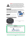
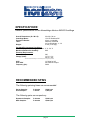
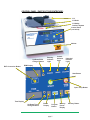
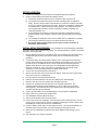
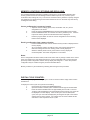
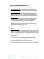
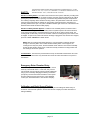
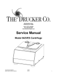
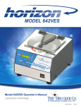
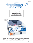
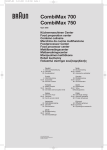
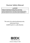
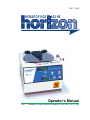
P/N 7711048
HEMATOFUGE
842 HS
Operator’s Manual
Rev. A
HEMATOFUGE HORIZON 842HS Laboratory Centrifuge
TABLE OF CONTENTS
Model Description
page 3
Supplied Equipment
page 3
Intended Use
page 3
Warranty Information
page 3
Specifications / Recommended spins page 4
Control Panel / Parts of the Centrifuge
page 5
Setup Location
page 6
Initial Setup Procedure
page 6
Operation
page 7
Rotor Configurations
Sixteen-Place, Microhematocrit/ serum/QBC Rotor
page 7
Default user settings
page 7
Advanced User Settings
page 8
Control Panel Functions
Time Adjustment and Timer Operation
Speed Adjustment / RCF Display
Starting and Stopping a Run
Unlocking the Lid
page 8
page 8
page 8
page 8
Advanced User Settings
Acceleration Rate
Braking Rate
Countdown Delay
Imbalance Detection
Audible Setting
page 8
page 9
page 9
page 9
page 9
Memory Locations / Storing and Recalling
page 10
Digital Cycle Counter
page 10
Care and Preventative Maintenance
page 11
Troubleshooting
page 12
Safety
page 13
Emergency Rotor Chamber Entry
page 13
Calibration and Earth Ground Testing
page 13
Replacement Parts
page 14
page 2
WARNING: For the safety of both the operator and service personnel,
care should be taken when handling substances that are known to be toxic,
radioactive or contaminated with pathogenic microorganisms when using this
centrifuge. When Risk Group II materials are used (as identified in the World
Health Organization “Laboratory Bio-Safety Manual”), a Bio-Seal should
be employed. The rotor and rotor accessories should not be considered as
Bio-Seals. More than one level of protection must be provided in the case of
materials of a higher group. The use of flammable or explosive materials as well
as those materials which chemically react vigorously is prohibited.
Model Description
The Hematofuge 842HS is a continuous-duty, digitally-controlled centrifuge designed for the
separation of fluid samples. The 842HS offers control over almost every aspect of the unit’s
operation from variable acceleration and deceleration to easy time and speed input. High speed
and force capability greatly reduce processing times. The
exclusive Drucker Microhematocrit rotor allows for quick
and easy sample loading and horizontal separation. Save
settings in one of 10 memory locations and recall them
at the touch of a button.
Intended Use
General purpose laboratory centrifuge for sample
separation.
SUPPLIED ACCESSORIES (Standard)
One (1) Sixteen-Place Microhematocrit/ serum/ QBC rotor
p/n7786050
Also included (not shown):
• One (1) Line Cord • One (1) Operator’s Manual WARRANTY:
The Drucker Company warranties that this centrifuge is free from
defects in workmanship and parts for 2 years.
Made in the USA by
200 Shadylane Drive • Philipsburg, PA 16866
Phone: 814-342-6205 or 814-692-7661 • Fax: 814-692-7662 • www.druckercompany.com
•The rotor and rotor accessories are rated for a rotational speed of 12,000 RPM (a force of 13,520 xg).
page 3
HEMATOFUGE
842 HS
SPECIFICATIONS:
General Specifications for the Hematofuge Horizon 842HS Centrifuge
Overall Dimensions (H x W x D): 20 x 28 x 34 cm
Centrifuge Motor:
1/2 H.P. Brushless DC
Protection Breaker:
4 Amp. re–settable
Timer:
electronic, with hold
or 0 to 99 minutes, +/- 1%
Weight:27 lbs (12.25 kgs)
Permitted Environmental Conditions:
Ambient Temperature During Operation: 2 °C - 50 °C
Maximum Relative Air Humidity: 90%
Electrical Requirements:
Power (Watts): Voltage (Volts): 200
115 (+/- 10)*
230 (+/- 20)*
653V 653V 230V Frequency (Hz): 115 Volts for US
230 Volts for Europe
50/60
*Check Serial Number Badge for Your Model Specific Voltage Requirement
RECOMMENDED SPINS
The following spinning times are recommended:
Serum Samples: Urine Samples: 2 minutes 1 minute 12,000 rpm
1,000 rpm
The following spins are compulsory:
Hematocrit Samples: QBC Samples: 5 minutes 5 minutes 12,000 rpm
12,000 rpm
page 4
CONTROL PANEL / PARTS OF THE CENTRIFUGE:
Lid
Lid Knob
Lid Safety
Interlock System
Control Panel
(see below)
Cabinet
Up/Down RPM
Change Buttons
RCF Conversion Button
Running
Indicator
Light
Locked
Indicator
Light
Unlocked
Indicator
Light
RPM Display
Start Button
Open / Stop Button
Time Display
Up/Down Time
Change Buttons
Brake
Display
Program
Button
page 5
Memory
Preset
Display
Memory Button
SETUP LOCATION:
1. Unpack the centrifuge and verify that all of the supplied equipment is present.
2. Choose a setup location which meets the following criteria:
a) A bench top clearance height of 40 cm is required in order to open the lid.
b) The clearance envelope is the space around the centrifuge which is required for safety. Choose a setup location which will allow for a clearance envelope of at least 61 x 61 cm, (with the centrifuge at the center). No person or hazardous material shall be permitted in the clearance envelope during operation. The operator time within the envelope shall be limited to the time necessary for loading, unloading and centrifuge operation only.
c) Proper ventilation is necessary to prevent the overheating of samples as well as premature failure of the centrifuge. Choose an area which will allow unencumbered air flow.
d) The centrifuge is designed to rest on its four rubber feet. No adjustment is necessary for leveling the centrifuge, however, the surface should be flat and level.
e)
Be sure the outlet is always within reach as the line cord is the means of emergency disconnection!
INITIAL SETUP PROCEDURE:
If any problems are found during the initial setup
procedure, refer to the troubleshooting section. For further assistance, contact The Drucker
Company. at 814-342-6205
1. Plug the female end of the line cord into the rear of the centrifuge. Plug the male end into an approved electrical outlet. For electrical safety, the unit must always be properly grounded.
2. For operator safety, the locking system is always active; requiring power and direction from the user to disengage it (the lid also automatically unlocks at the end of a run when it is safe to do so). To unlock the lid (in order to access the rotor chamber) press the ‘OPEN / STOP’ button on the control panel. The ‘UNLOCKED’ indicator light should illuminate. If it does not, refer to the section on troubleshooting. The lid will remain unlocked for 15 seconds after pressing the ‘OPEN / STOP’ button.
3. Turn the lock counterclockwise and open the lid.
4. Spin the rotor by hand; check for free and level rotation. If the rotor does not spin freely, refer to the section on troubleshooting.
5. Turn rotor lid knob counterclockwise to remove.
6. Place the test tubes inside the rotor and verify that they are seated properly.
7. Place the rotor lid on the rotor and turn knob clockwise until snug.
8. Close the lid. Rotate the lid knob clockwise to its complete stop position. The ’LOCKED’ indicator light should be illuminated. If it is not, make sure that the lid is locked properly. The centrifuge will not run unless the lid is latched properly and the ’LOCKED’ indicator light is illuminated.
9. Use the up arrow button next to the RPM display to set the speed to 12000 RPM.
10. Initiate a test run by pressing the ‘START’ button.
11. The ‘RUNNING’ indicator light will illuminate. 12. The unit will accelerate to the current set speed.
13. Listen to the sound of the centrifuge. A smooth whirring sound should be heard. If there are any loud or unusual sounds, stop the centrifuge by pressing the ’OPEN / STOP’ button
immediately and refer to the section on troubleshooting.
14. Press the ‘OPEN / STOP’ button to terminate the test run. The rotor will decelerate to a complete stop and the lid will then unlock automatically for sixty (60) seconds.
15. Take time now to familiarize yourself with the various additional user settings. Turn to page 8.
16. The centrifuge is now ready for operation.
page 6
OPERATION:
NOTE: Follow the initial setup procedure before initial operation.
1. Press the ‘OPEN / STOP’ button to unlock the lid and then open the centrifuge lid.
2. Turn rotor lid knob counterclockwise, and remove rotor lid.
3. Place the test tube samples into the rotor. Be sure to follow the rules for balanced loads.
4. Put the rotor lid in place and turn the lid knob clockwise until snug, do not over tighten.
THE ROTOR LID MUST BE IN PLACE BEFORE OPERATING THE CENTRIFUGE!
5. Close the centrifuge lid and turn the lid knob clockwise to its complete stop position. The
’LOCKED’ indicator light should illuminate to indicate that the latch is closed properly. If
the lid knob is not completely latched, the ‘LOCKED’ indicator light will not illuminate
and the centrifuge cannot be operated.
6. Set the desired speed and run time using the appropriate up and down arrow buttons,
or select the desired memory location.
7. If desired, adjust the braking level, acceleration rate, countdown delay, imbalance
sensitivity and audible indication. Turn to page 11 for a description of these features.
8. Begin the run by pressing the ‘START’ button on the control panel.
9. The centrifuge should begin to spin. The ‘RUNNING’ indicator light should illuminate.
IF A PROBLEM IS FOUND DURING A SPIN THAT REQUIRES THE CENTRIFUGE
TO SHUT DOWN, PRESS THE ‘OPEN / STOP’ BUTTON IMMEDIATELY!
10. After time has elapsed, the ‘RUNNING’ indicator light will extinguish and the rotor will
decelerate to a complete stop.
11. The ‘UNLOCKED’ indicator light will illuminate and the locking mechanism will
disengage, allowing entry into the rotor chamber. If the automatic unlock times out
(after 60 seconds) simply press the ‘OPEN / STOP’ button.
12. Turn the centrifuge lid knob counterclockwise and open the lid.
13. Turn rotor lid knob counterclockwise, and remove rotor lid.
14. Remove the samples.
15. The centrifuge may be used immediately.
Rotor Configurations:
The next section describes proper balancing and tube loading. Use the appropriate section for the
rotor installed in your centrifuge. Improper loading can result in damage to the centrifuge or test
tube samples.
Sixteen-Place Microhematocrit, serum and QBC Rotor (Standard):
This rotor is designed to hold up to 16 standard 1.5mL microtubes and 16
hematocrit/ QBC tubes. All tube types can be spun at the same time if needed.
Your centrifuge must contain a balanced load in order to work properly. To ensure
that the load is balanced, keep these rules in mind when inserting test tube samples.
1. Opposing tube locations must be empty or loaded with equally weighted samples.
2. If an odd number of samples is to be spun, use a water-filled tube to mate with the
unpaired one.
DEFAULT USER SETTINGS:
NOTE: Your centrifuge comes pre-set with the following settings:
Braking Rate: 9
Acceleration Rate: 9
Countdown Delay: ON
Imbalance Detection: LOW
Audible Setting: 4
(See page 8/9 for a description of the user settings)
page 7
CONTROL PANEL FUNCTIONS:
Time Adjustment and Timer Operation - The run time may be set from 30 seconds to 99
minutes and 30 seconds. Press the up and down arrow buttons next to the time display to adjust
the run time. Adjustments may be made prior to a run or after a run begins. A quick tap will adjust
the time by 30 seconds. Hold down the button for 1 minute adjustments - continue to hold for 5
minute adjustments.
Press the down button once while 00:30 is displayed to access the “hold” feature. When a “hold”
run is initiated, the timer will count up to keep track of total run time. The unit will run for a maximum
of 99 minutes and 30 seconds and will then shut off automatically. The “hold” run may also be
terminated by pressing the STOP/OPEN button. The total run time during a “hold” run is displayed
on the time display until the operator unlocks the lid by pressing the OPEN button or opens the lid
(during the automatic unlock after the run ends).
Speed Adjustment / RCF Display - Press the up and down arrow buttons next to the speed
display to change to run speed. Adjustments may be made prior to a run or after a run begins.
A quick tap will adjust the speed by 50 RPMs. Hold down the button for 100 RPM adjustments.
Continue to hold for 500 RPM adjustments.
Press the RCF button at any time to convert the current speed setting to the corresponding force
value (xg). The speed may be set by RCF by holding down the RCF button while using the up/
down speed set buttons. The jumps made in the RCF value while holding down the RCF button and
pressing the up and down arrow buttons correspond to 50 RPM adjustments in speed. Since the
RCF is a function of the square of the speed, this jump size will vary.
Starting and Stopping a Run - With the lid switch closed, press the START button to begin a
run. Press the STOP/OPEN button at any time during a run to terminate it.
Unlocking the Lid - The lid is unlocked whenever the red UNLOCKED indicator light is
illuminated. The lid unlocks automatically for 60 seconds at the end of a run. The lid can also be
unlocked for an additional 15 seconds by pressing the OPEN/STOP button while the unit is idle.
The lid cannot be unlocked while the rotor is spinning.
Imbalance Detection Reset - This centrifuge is equipped with imbalance detection. If an
imbalance is detected, the centrifuge will terminate the current run and will begin to brake to a stop.
The words “BALANC” and “ERROR” will flash on the speed display. Once the rotor has stopped,
open the lid to cancel the error reporting, balance the load and begin a new run. Alternately, the
error reporting can be canceled by pressing the OPEN/STOP button.
ADVANCED USER SETTINGS:
This centrifuge allows for total control of the run by the user. You may adjust the acceleration rate,
adjust the braking rate, adjust the imbalance sensitivity level, select from several audible settings,
and use the optional countdown delay.
Acceleration Rate - The user may adjust the acceleration rate from minimum (1) to maximum
(10) using the following procedure:
1. While the centrifuge is idle, press the PROGRAM button.
2.
Use the UP/DOWN arrow buttons next to the speed display until “ACCEL” is displayed in the speed display.
3.
The current acceleration rate is displayed in the time display. Use the ‘UP/
DOWN arrow buttons next to the time display to adjust the acceleration rate from 1 (minimum) to 10 (maximum).
4.
Press the PROGRAM button to exit or use the UP/DOWN arrow buttons next to the speed display to adjust additional settings.
page 8
ADVANCED USER SETTINGS (continued):
Braking Rate - The user may adjust the braking rate from minimum ( slowest deceleration, 0) to
maximum (quickest deceleration, 9) using the following procedure:
1.
While the centrifuge is idle, press the PROGRAM button.
2.
Use the UP/DOWN arrow buttons next to the speed display until “BRAKE” is displayed in the speed display.
3.
The current braking rate is displayed in the brake display. Use the UP/DOWN arrow buttons next to the brake display to adjust the braking rate from 0 (minimum) to 9 (maximum).
4.
Press the PROGRAM button to exit or use the UP/DOWN arrow buttons next to the speed display to adjust additional settings.
Countdown Delay - When the countdown delay is turned on, the timer will not begin
decrementing until the rotor has reached full speed as set by the user. This feature ensures that
the samples see full force for the total run time.
1.
While the centrifuge is idle, press the PROGRAM button.
2.
Use the UP/DOWN arrow buttons next to the speed display until “CNTDLY” is displayed in the speed display.
3.
The current status of this feature (ON or OFF) is displayed in the time display. Press UP/DOWN arrows next to the time display to toggle the status between ON and OFF.
4.
Press the PROGRAM button to exit or use the UP/DOWN arrow buttons next to the speed display to adjust additional settings.
Imbalance Detection - This centrifuge is equipped with imbalance detection. This ensures that
the centrifuge will safely shut down in the event that an imbalanced load is run or a malfunction
occurs. This feature is intended to provide for operator safety and to extend the life of the
centrifuge. The LOW setting will allow for a greater imbalance before shutting the centrifuge down.
1.
While the centrifuge is idle, press the PROGRAM button.
2.
Use the UP/DOWN arrow buttons next to the speed display until “BALANC” is displayed in the speed display.
3.
The current status of this feature (LOW or HI) is displayed in the time display. Press UP/DOWN arrows next to the time display to toggle the status between LOW and HI.
4.
Press the PROGRAM button to exit or use the UP/DOWN arrow buttons next to the speed display to adjust additional settings.
Audible Settings - The user may select from six different audible indicator levels:
Setting Button Press Beep?
1NO
2YES
3
NO
4
YES
5
NO
6
YES
1.
2.
3.
4.
End-of-run audible notification
NONE
NONE
YES, 5 beeps
YES, 5 beeps
YES, continuous, user must press STOP/OPEN button to cancel
YES, continuous, user must press STOP/OPEN button to cancel
While the centrifuge is idle, press the PROGRAM button.
Use the UP/DOWN arrow buttons next to the speed display until “BEEPER” is displayed in the speed display.
The current audible selection is displayed in the time display. Use the UP/
DOWN arrow buttons next to the time display to select a setting (1 to 6).
Press the PROGRAM button to exit or use the UP/DOWN arrow buttons next to the speed display to adjust additional settings.
page 9
MEMORY LOCATIONS / STORING AND RECALLING:
The Hematofuge 842HS centrifuge is capable of storing up to 10 user-defined presets.These
memory presets contain all of the settings needed to define a specific run, (run time, speed,
acceleration rate, braking rate, etc.). The user can use these memory locations to quickly configure
the centrifuge for a specific test type and ensure that the test is run in the same way each time by
recalling this same setting.
Store a configuration in a memory location
1.
2.
3.
4.
Adjust the various settings (speed, time, acceleration rate, etc.) for the configuration to be saved.
Press and hold the PROGRAM button until the preset display begins to flash.
Press the MEMORY button to increment the memory location by one. Continue to press the memory button until the desired location is displayed.
Press the program button to store the current configuration into the memory location that is displayed.
Recall a configuration from a memory location
1.
Press the MEMORY button until the desired memory location is displayed in the memory display.
2.
As you review the presets, the settings on the control panel will change to reflect the settings stored in the memory preset currently displayed.
3.
When the desired preset is found, pause and the memory display will momentarily flash. The stored configuration is now loaded.
Notes:
Once a configuration has been loaded, it will remain active until any change is made on the control
panel. If for instance the user adjusts the time, the current configuration will no longer match the
previously loaded configuration and the memory display will change to a “-” dash. The previous
configuration may be recalled using the procedure described above.
Memory locations my be overwritten by selecting them during the store procedure.
DIGITAL CYCLE COUNTER:
This centrifuge is equipped with a digital cycle counter to monitor machine usage and for routine
maintenance.
To display the current cycle count, perform the following:
1.
Unlock the lid by pressing the OPEN/STOP button.
2.
Open the lid latch so that the yellow LOCKED indicator light is not illuminated.
3.
Press and hold the START button for approximately five seconds. The word “CYCLES” will be displayed in the speed display and the current cycle count will be displayed in the time display. If the current cycle count exceeds 9,999 cycles, the cycle count will be displayed by showing the first part of the number and then the end of the number. For example: the 1st shown is 0002 and the 2nd shown is 4537 represents 24,537 cycles.
page 10
CARE AND PREVENTATIVE MAINTENANCE:
With proper care and maintenance your Horizon centrifuge will provide years of laboratory service.
For proper care, the following steps should be taken:
1.Provide Adequate Ventilation: For cooling purposes, the Horizon draws in ambient air through the air intake cover on the top of the lid and exhausts this air in the rear of the base. The centrifuge should be placed on a hard smooth surface for good air circulation.
2.Always Spin Balanced Loads: This centrifuge is equipped with imbalance detection. However, it is still possible to run loads that are minimally imbalanced, particularly at an imbalance setting of LOW SENSITIVITY. For maximum centrifuge life, set the imbalance detection to HI SENSITIVITY and always run balanced loads. Refer to pages 8 and 9 on for additional information on balancing the load.
3.Keep the Rotor Clean: NOTE: Always follow the safety guidelines of your laboratory to
properly clean up and/or dispose of materials in the event that a substance known to be
potentially toxic, radioactive or contaminated with a pathogenic microorganism is spilt in
or on the centrifuge. Small glass fragments left in the rotor after a tube breakage
may adhere to the next test tube inserted in that position. When this tube is handled,
these fragments may puncture protective gloves and lacerate the operator’s fingers or hand.
Remaining fragments may provide stress points on subsequent tubes and result in additional
breakage. If a tube breakage occurs, carefully remove the tube. Properly dispose of the
sample and tube fragments and thoroughly clean the rotor.
4.Motor and Electrical Maintenance: This centrifuge uses a brushless-DC motor. There are no brushes to replace and it should not need routine servicing for the life of the centrifuge. The electrical components are selected for high reliability and should not need service.
5.Keep the Centrifuge Clean: The cabinet, rotor top and accessories shall be thoroughly cleaned using either isopropyl alcohol, soap and water. Must be Lysol (1/4 cup/gallon) or “Cidex”. Not all Lysol will be sufficient (must be a Lysol Amphyl disinfective cleaner or Virkon). The use of Fully/Partially Halogenated Hydrocarbons, Ketones, Esters and all other chemicals not prescribed by the manufacturer may cause damage to the rotor and tube carriers / holders and shall not be used. Before using any cleaning or decontamination methods except those recommended by the manufacturer, users should check with the manufacturer that the proposed method will not damage the equipment.
If it is necessary to remove the rotor for additional cleaning it is required that a qualified
technician remove the rotor assembly.
Apply cleaning solutions with a towel or cloth. Do not submerge the centrifuge in water or other cleaning solutions as this will cause damage and void your warranty!
If hazardous material is spilt on or inside the centrifuge, the centrifuge must be decontaminated.
page 11
TROUBLESHOOTING:
1. Problem:
Solutions:
2. Problem:
Solutions:
3. Problem:
Solutions:
The rotor does not spin freely.
• Make sure that nothing has fallen into the rotor chamber.
• If there is nothing obstructing the rotor, the motor may be damaged. Contact
your authorised dealer or The Drucker Company for further assistance.
There is excessive noise when the machine is running.
• Check to see that the load is balanced.
• Make sure that nothing has fallen into the rotor chamber.
• Make sure that the screw in the center of the rotor is snug.
• The motor may be damaged. Contact your authorised dealer or The Drucker
Company for further assistance.
The centrifuge does not run or an error message is displayed.
• Make sure that the centrifuge is getting power. Does the control panel come
on? Check the electrical outlet that the unit is plugged into. Check the circuit
breaker on the base near the rear of the centrifuge.
• If the unit is getting power, make sure that the lid latch is closed properly.
The latch is closed properly when the yellow ‘LOCKED’ indicator light is
illuminated.
• If the centrifuge stops soon after start-up and ‘ERROR’ is displayed on the
speed display, refer to the following table for fault information:
ERROR / SPEED
The centrifuge cannot reach full speed due to a problem with the rotor, an inadequate power supply, or other electrical problems. Press the OPEN/
STOP button to cancel the error and then check the rotor and the line voltage. Contact your authorised dealer or The Drucker Company.
ERROR / BALANC
The centrifuge has detected an imbalance. Press the OPEN/STOP button to cancel the error and balance the load. If the load is balanced, make sure that the centrifuge is installed on a secure, level location.
4. Problem:
Solutions:
The lid knob cannot be turned / the lid cannot be unlocked.
• Make sure the centrifuge has power and that the rotor is stopped. Press the
‘OPEN/STOP’ button. The red ‘UNLOCKED’ indicator light should illuminate
and the unlocked mechanism should disengage, allowing entry into the lid.
• If the lid is still locked, make sure that the red ‘UNLOCKED’ indicator
is illuminated and turn the lid knob first completely clockwise and then
counterclockwise.
• If the red ‘UNLOCKED’ indicator will not illuminate or the locking mechanism
will not disengage, the electronics or locking mechanism may be damaged.
Have a technician service the centrifuge or contact The Drucker Company for
further assistance.
For additional assistance, services and technical support
contact The Drucker Company LTD.
page 12
SAFETY:
The Hematofuge 842HS complies with all requirements of CE EN 61000-3-2, -3-3, EN
61000-4-2, -4-3, -4-4, -4-5, -4-6, -4-11, EN 61010-1, -2-020 and UL standard 3101–2–20,
Can/CSA C22.2 No. 1010.1 , Can/CSA C22.2 No. 1010.2.20
Horizon Lid Safety Switch: The Horizon lid is secured to the top of the cabinet by a locking knob
and pawl system. When the knob is rotated clockwise, the pawl grips the underside of the cabinet
opening and prevents the lid from opening. A mechanical stop positions the pawl and prevents it
from rotating completely. When rotated to the stop position, the pawl makes contact with a micro–
switch mounted underneath the cabinet top.The lid safety switch prevents the centrifuge from
operating while the lid is open. The yellow ‘LOCKED’ indicator light on the front of the machine will
illuminate when the lid has been locked properly.
Horizon Lid Safety Interlock System: In addition to the Lid Safety Switch, the Horizon has a
true “0 RPM” lid locking system. The lid safety interlock system keeps the lid locked at all times,
(even during power failure), and requires that the rotor be at rest in order to unlock the lid. The
centrifuge will not allow entry into the rotor chamber unless the centrifuge has power and the rotor
is stopped. To open the lid, make sure that the centrifuge is plugged in and, with the rotor stopped,
press the ‘OPEN / EMERGENCY STOP’ button.
NOTE: After the centrifuge has started spinning, it may be possible to rotate the lid knob
enough to cause the pawl to lose contact with the lid safety switch. If this happens, the
centrifuge motor may lose power, but the lid will still remain locked. If the knob is accidentally
moved and this situation should occur, rotate the knob fully clockwise to its stop position and
the centrifuge will resume operation.
Circuit Breaker: The Horizon is protected with a 4 Amp circuit breaker located at the rear of the
machine mounted to the base. Any electrical short circuit will cause the breaker to cut power to
the machine.
Emergency Rotor Chamber Entry:
In the event of power failure, it may be impossible to unlock
the lid by conventional means. In this case, entry into the
rotor chamber may be made by removing the latch label and
using a pen to manually disengage the locking mechanism
(see photo). Pull the mechanism towards the control panel
and then unlatch and open the lid. If the unit is damaged,
contact your authorised dealer or The Drucker Company.
Calibration and Earth Ground Testing:
It is recommended that the top speed, ground continuity and line leakage be tested every 12
months for continued safe operation. Contact The Drucker Company for further information or
testing availability.
page 13
Contact your authorised dealer or The Drucker Company
to order replacement parts or accessories.
Replacement Parts:
Part No. Description
7751068
7723002
7735052
7717041
3056001
3056003
7751043
7724162
7760004
7760006
7714101
7714103
7712256 7724071
7732018
7786050
7724177 7712234 7732020 Lid Tray Micro-Switch
Lid Tray Solenoid
Motor, 1/2 H.P. Brushless DC
PC Control Board
Step Down Transformer (115V)
Step Down Transformer (230V)
Circuit Breaker
Front Panel Label
Line Cord (U.K.)
Line Cord (U.S.)
Pawl, Lock, lid
Knob, Lock, lid
Lid
Hinge, friction
Gasket, cabinet opening
Microhematocrit/ serum/ QBC rotor
Suction foot
Rotor Lid
Microhematocrit Gasket
One (1) Sixteen-Place Microhematocrit/ serum/ QBC rotor
p/n 7786050
Made in the USA by
200 Shadylane Drive • Philipsburg, PA 16866
Phone: 814-342-6205 or 814-692-7661 • Fax: 814-692-7662 • www.druckercompany.com