1
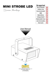
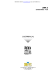
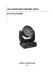
Product Parameter Led Source: 3W(Blue) 80 150 User Manual 12V/1.5A 7W 220 0.8kg -4- 150 80 -1- OPERATING INSTRUCTIONS INTRODUCTION Product Overview LED Output Manual Mode Access the three different operating modes available in this fixture by using the <WORK MODE> button on the front panel. Press < WORK MODE > to cycle through the modes. Please see a description of each mode below. Mode Button LED Indicator Laser Output Mode Description Microphone Wireless Remote Green Laser Dimmer 12 V Power In Cooling Fan Affected by environmental temperature control fan to run or stop automatically 1.Sound-active The LED indicator on the front of the fixture will be green when the Sound-active mode is selected. 2.Autorun The LED indicator on the front of the fixture will be red when the Autorun mode is selected. 3.Autorun and Sound-active auto-switching The LED indicator on the front of the fixture will be orange when the Autorun and Sound-active auto-switching mode is selected. Wireless Remote (IR) Select to the Sound-active work mode SETUP AC Power This fixture includes an external power supply which is auto-ranging and runs on 100~240 VAC, 50/60 Hz power. Only use the included power supply! To obtain a replacement power supply, contact us! To determine the power requirements for a particular fixture, see the label affixed to the back plate of the fixture or refer to the fixture's specifications chart. A fixture's listed current rating indicates its average current draw under normal conditions. Always connect the fixture to a switched circuit. Never connect the fixture to a rheostat(variable resistor) or dimmer circuit, even if the rheostat or dimmer channel is used only as a 0 to 100% switch. Select to the Autorun or the Autorun and Sound-active auto-switching work mode Select the laser color in forward order Select the laser color in reverse order Turn the led on/off or select the led color in forward order Turn the led on/off or select the led color in reverse order Reduce the sensitivity of the microphone Always connect the fixture to a circuit with a suitable electrical ground. Mounting Turn the laser and led on/off Increase the sensitivity of the microphone 1 2 3 4 5 6 Adjustable Stand Rigging Be sure that the structure can support the weight of the fixture. Please see the “Technical Specifications” for a detailed weight listing. Mount the fixture securely. Do this with a screw, nut and bolt, or a Angle Adjustment hanging clamp. When rigging, consider routine Knob maintenance. Please see the following notes on installation. • When aiming the fixtures, you may use the bracket adjustment knob(s). Loosen the knob(s), adjust to the desired angle, and then tighten the knob(s) by turning clockwise. Do not use tools for this step, as it may cause damage. -2- Press to activate one of the 6 auto programs Angle Adjustment Knob Auto Programs Auto Program Description 1 / 3 / 5 . work with only laser 2 / 4 / 6 . work with laser and led The wireless Remote (IR) will immediately override the <MODE> button. No additional settings are required! -3-