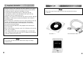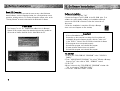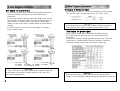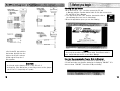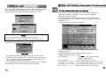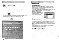
1
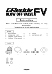
Please read this instruction manual carefully, and proceed with the
installation ONLY if you fully understand this manual_ Make sure to pay
attention to all the "Important!" 'Warning!" and "Caution!" messages
through out the manual.
Important!
・ This product is legal for sale or use in California only on vehicles
which may never be driven on a public highway.
・ This product is only for vehicles with 12V (battery) systems.
・
・
・
・
・
・
・
・
Warning!
Installation and use of this product should only be performed by a
trained specialist, who is very familiar with the automobile's
mechanical, electrical, and fuel management systems, if installed
by untrained person, it may cause damage to the unit as well as the
vehicle.
When using a soldering iron or other tools for installation, make
sure you read and understand the tool's user manual. Mis-use of
these tools can cause serious injuries.
Never tune the E-manage while the vehicle is moving.
Never tune the e-Manage on public highways. This can be
dangerous to you and others on the road.
When tuning and operating the vehicle in a garage, make sure that
the garage is equipped with a proper ventilation system.
After installation and tuning, make sure to clean up every thing that
would interfere the driver. Wires, tools, and laptop computer may
interfere with the driver and cause accidents.
Avoid open sparks, flames, or operation of electrical device
near flammable substances.
Make sure there are no leaks in the fuel system and that all of the
connections are secure.
1
・ Improper tuning of the e-Manage can cause damage to the engine.
・ GReddy Performance Products Inc. will not take an responsibility
of damage caused by improper installation or tuning .
・ Tuning should be performed only by a technician who full
understand the vehicle's fuel management and ignition timing
requirement for the engine being tuned.
・ Always s use a proper air/fuel ratio meter when tuning the e-Manage.
・ Installation of this product requires modification of the vehicle's
electrical system.
・ When making wire connections, be sure to remove the key from the
ignition, and disconnect the negative terminal of the battery.
・ Never short out the system. It can damage the unit as well as
the vehicle's electrical system.
・ Read and fully understand the wiring diagram before making any
wire connection.
・ When connecting the connector, push it in all the way until you hear
them click in together.
・ The communication cable is not a repairable item, so please take
care of it. When disconnecting from the PC (laptop), pull holding the
connector. Never pull on the cord.
Please
・ Check the parts list and make sure you have received all the items
in the list.
CD ROM x 1
Communication Cable x 1
Please
・ The product and the instruction manual are subject to change
without notice.
2
Instruction Manual x 1
3
This product will allow the tuner to program GReedy e-Manage
functions, by linking the e-Manage and a WindowsR based PC. This
product is only for the vehicles equipped with GReddy e-Manage.
Features :
・ Air Flow Adjustment Map
This 16 xl6 (rpm x throttle position) table is used to fine-tune the input
signal of the Air Flow Meter or MAP Sensor to the ECU for fuel enrichment.
・ Upgrade Injectors
Controls upgrade injectors. (up to 150% larger than factory)
・ Upgrade Airflow meters
Controls upgrade Airflow meters.
・ Boost limiter cut feature
Eliminates factory boost limiter.
・ Anti Engine Stall feature
This is used to stabilize the rough idle due to turbo compressor surge,
Blow-off valve vented out to the atmosphere or use of a high lift camshaft.
・ VTECR Setting
This is used to set the VTEC setting without going in to the Main Unit.
・ Map Trace feature
This allows the tuner to pin point the current location on any map table.
・ Real Time Display feature
Before installation of the software, please make sure that the PC is set
up correctly. This product will only operate on Wlndows R 95, 98, Me, or
2000, that meets the requirements listed below.
System Requirements
・
・
・
・
・
・
・
IntelR PentiumR 166MHz or faster processor
At least 32MB of RAM (e4MB recommended:)
A hard drive with at least 50MB of free space.
A SVGA monitor (800x600) and al6bit (high color) display
A3.5inch 1.44MB floppy disk drive
A CD-ROM drive
Serial port with RS-232C D-Sub 9 pin connector (male)
Important
・ If the Serial port is not D-Sub 9 pin connecter (male), an adapter will
be necessary to connect the communication cable.
・ For computers that are not equipped with a Serial port, a USB to
Serial adapter is required Do not use USB to USB cable.
This allows the tuner to monitor the engine condition in real time.
・ Real Time Communication
This allows the PC and e-Manage to communicate at real time. Any
changes made on the computer screen is sent to e-Manage with in 2-3 sec.
・ Data Logging feature
This allows the tuner to view the data recorded and saved during the realtime mode in graph form.
・ Security Setting feature
This allows the tuner set up a password to apply a security lock to the data
in the main unit.
Optional Parts:
・ Harness Kit (Injector control)
This harness is used when controlling main injectors or sub injectors
If your computer meets the requirement listed above, the basic features
of this program will operate, but to use the "Real Time Monitor'
feature requires the following.
Required to use the "Real Time Monitor”
・ IntelR Pentium ⅡR 266MHz or faster processor
・ At least 128MB of random-access memory (RAM)
As for the setup and installation of the Windows R , please refer to the
"Getting Started" manual included in the Windows R Software.
・ Harness Kit (Ignition Timing Control)
This harness is used when controlling the ignition timing.
・ GReddy Pressure Sensor
GReddy pressure sensor can be used for the scale of each Map table. This
is used when the factory system exceeds the Air Flow Meter or MAP sensor
capacity.
4
5
Follow the instructions listed below to install the Support Tool software.
Basic PC Operation
This system will basically operate the same as any other WindowsR
based software, such as changing window size, closing window, mouse
operation, quitting, and etc. For further information, please refer to the
"Getting Started" manual included with the Windows R Software.
Please Note
・ The Support Tool v1. 10 software has a Main Unit (e-Manage)
Update v1.20 program that will automatically detect and update an
old version unit when the Main Unit is linked With the PC.
Software Installation
1 . Turn Personal Computer "ON"
2. Insert the Support Tool CD-ROM in the CD-ROM drive. This
software is a self installing software, so installation will begin
soon as the CD-ROM is inserted. Follow the instruction on
the screen.
3. After the installation is complete, GReddy e-Manage
short cut icon will appear on the desktop.
Important
・ If the self installation fails
Depending on the computer's settings, it will not allow self
installation. When this happens double click the "setup. exe"
in the "DISK1 " folder in the CD-ROM to install the software.
・ If the program does not operate properly
Uninstall the program, and reinstall the program.
・ If communication feature does not operate
Uninstall the program, and reinstall the program.
To uninstall
1. Click on the "ADD/REMOVE PROGRAM" in the "CONTROL
PANEL".
2. From "ADD/REMOVE PROGRAM" list, select "GReddy e-Manage
Support Tool", then click on "ADD / REMOVE" button.
3. Click "OK"
4. When it return to the "ADD/REMOVE PROGRAM" window dick
"OK' to go back to "CONTROL PANEL".
5. Close the "CONTROL PANEL" window.
6
7
Wire diagram for Injector Signal
・ Please read the instructions included with the Injector Harness kit,
and proceed with the wiring only if you fully understand the
instructions.
・ Connect to the vehicle's Injector signal wires. Refer to the 'Vehicle
Specific ECU wire location chart" at the end of this manual for the
proper location of each wire. Make sure that you connect same
number of wires as the engine's cylinder number. (Excludes Rotary
engines)
・ For Rotary engines, you can only wire the primary or secondary
injector signal or both.
Wire diagram for Sub Injector Signal
・ When using the I/J CH-A, I/J CH-B for sub injectors, set the jumper
JP5 and JP6 in the e-manage main unit to "1-2" from "Open".
Important
・ If the vehicle does not have the same number of injector signal wire
as the number of the engine's cylinders, group 2 wires in to one.
Wire diagram for Ignition Signal
・ Please read the instructions included with the Ignition Harness
Kit, and proceed with the wiring only if you fully understand the
instructions.
・ Connect to the vehicle's ignition signal wires. Refer to the "ECU wire
location chart" in this manual for the proper location of each wire.
・ Connect the ignition channel wire in the engine's firing order.
Important
・ If the vehicle does not have the same number of injector signal wire
as the number of the engine's cylinder number, group 2 wires in to
one. See the diagram above.
Important
・ Make sure that wires are connected in the firing order and jumper
setting is correct. Improper wiring and setting can damage the ignition coil.
9
8
Starting the application
1. With the IG key in "OFF" position, connect the PC, and
e-Manage using the Communication Cable. D-Sub 9pin connector to
PC and USB to the e-Manage.
2. Turn the IG key to the "ON" position, then double click on
the e-Manage short cut icon on tile desktop.
3. When the application opens, you see the following.
Please
・ Use only the provided communication cable. If a different cable is
used, it might damage the PC or/and the e-Manage.
* On Honda EG type vehicles,
the bottom third pin from the
right on the 26 pin is also an
ignition signal. Group the 2
wire together.
Important
・ On Honda, set the jumper pins JP 1 and JP2 to 2-3.
・ After wiring, if the tachometer, or not firing occurs, set the jumper
pin JP2 to 2-3. (especially on Toyotas)
10
Download the communication Program (Main Unit Update)
1 . Always disconnect the 12 pin connector on the main unit.
2. Check and make sure that the status bar is displaying "ONLINE". If it
does not show “ONLINE”, Check the COM port setting.
11
3. The program will automatically detect a unit will old system program.
When the update window shows up on the screen,, click "OK” to
start downloading the update. Download will take about 2 min.
Main Unit Setting Information Confirmation
1. Turn the IG key to "ON" position and check to make sure that the
status bar is displaying "ONLINE". If it does not show "ONLINE",
Check the COM port setting.
2. To confirm the Main Unit Setting Information, select the "Main Unit
Setting Information" in the "Setting" or click on the "Main Unit Setting
Information" icon.
* Changes can not be made in this window.
Please
・ Do not disconnect the communication cable during the
communication. PC and the e-Manage will not function properly.
4. When the updating is complete, the following window will pop up.
Turn the IG key to "OFF" position and click "OK".
Important
・ The updated program will confirm once the unit is turned “OFF”.
・ When the unit is turned back "ON", the following message will come
up. "The data in the Main Unit was lost! Please export data.” this
shows that the unit was properly updated.
5. This completes the update of the communication program. If the 12
pin connector was disconnected, please reconnect it back.
・ For the Rotary switches I -3 setting information please refer to the
e-Manage manual.
・ For the Ignition Input Jumper Setting, refer to the "Wire
diagram for Ignition Harness" on page
.
Air Flow Meter 1 - - - - - - - -Used for Hot wire, flap type airflow
meters, or MAP sensors
・ Air Flow Meter 2 - - - - - - --Used for GTR(Skyline), or VTEC
・ Airflow Meter Pulse Input- - -Used for Karman type airflow meters or VTEC
・ Airflow Meter Pulse Output - Used for Karman type airflow meters or VTEC
・ A.A.V. Value - - - - - - - - Displays the Main Unit's AAV settings.
13
12
Parameter Setting
Parameter Setting
This window allows you to change Airflow Meters, Injectors, set the
Throttle, aThrottle, and select which map to use.
To read the program in the Main Unit, select the "Import Data" in the
"Communication" menu bar or click on the "Import Data" icon.
' To show the Parameter Setting, select the "Parameter Setting" in the
"Settings" menu bar or click on the "Parameter Setting" icon.
Air Flow Meter Change
・ When the Airflow meter or MAP sensor is upgraded, check the
Sensor Type from the 'Vehicle Specific ECU wire location chart",
and select it from the pull down menu.
・ The Airflow Type programmed with the Main unit's rotary switch will
display as "Main Unit Setting" in the pull down menu.
* When the airflow meter is
upgraded, the airflow signal value
will change. Make sure to check
Air/Fuel Ratio with a proper
equipment to ensure proper fuel
mixture.
GReddy Pressure Sensor
・ Choose this box when an optional GReddy pressure sensor will be
used for the scale of each Map tables.
・ This function is used when the system exceeds the Air Flow Meter's
capacity. The factory ECU will continue to read off the Air Flow
Meter, but the e-Manage system will work off the GReddy pressure
sensor.
・ In the Sub Injector Map, the injectors can be controlled by rpm
and the GReddy pressure sensor signal.
Absolute Pressure Sensor Change
・ This function is used when the system exceeds the factory MAP
Sensor capacity. The factory ECU will continue to read off the
factory MAP sensor, but the e-Manage system will use the
calculated absolute pressure from the factory and GReddy pressure
sensor.
* Use Absolute Pressure Sensor when setting the vacuum as "O"
value.
* Use Relative Pressure Sensor when setting atmospheric pressure
as "O" value.
14
15