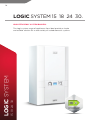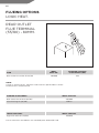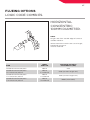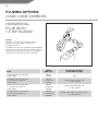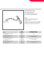
1
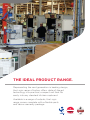
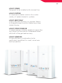
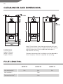
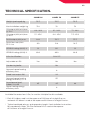
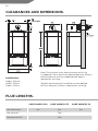
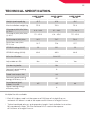
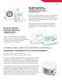
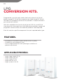
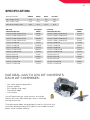
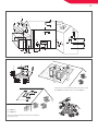
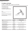
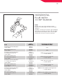
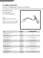
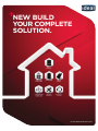
NEW BUILD YOUR COMPLETE SOLUTION. IDEAL BOILER STELRAD RADIATOR CYLINDER SOLAR PANEL FREE DESIGN STAGE SAP DESIGN SERVICE 364 DAYS A YEAR (USUALLY £50) WWW.IDEALBOILERS.COM 02 WELCOME TO FIRST CLASS. OUR AWARD WINNING BOILERS GO THROUGH 200 QUALITY CHECKS BEFORE THEY LEAVE THE FACTORY, AND ARE AVAILABLE WITH A RANGE OF FLEXIBLE WARRANTY OPTIONS. YOU CAN REST ASSURED RELIABILITY IS GUARANTEED WHEN YOU PARTNER WITH IDEAL. 03 CONTENTS. 04 06 14 22 30 38 46 50 THE IDEAL PRODUCT RANGE LOGIC COMBI LOGIC SYSTEM LOGIC HEAT LOGIC CODE COMBI ES LOGIC COMBI ES CONTROLS LPG CONVERSION KITS 52 FLUE SITING 54 FLUEING OPTIONS 79 CONTACT IDEAL 04 THE IDEAL PRODUCT RANGE. Representing the next generation in heating design, the Logic range of boilers offers state-of-the-art technology in a practical, compact unit that fits easily into any standard kitchen cupboard. Available in a range of outputs, the Logic range comes complete with a flexible parts and labour warranty package. 05 LOGIC COMBI Designed to be installed with minimal fuss. LOGIC SYSTEM A simple and reliable solution for a wide variety of sealed domestic systems. LOGIC HEAT ONLY Highly efficient and easy to operate, thanks to straightforward controls featuring a clear digital display. LOGIC CODE COMBI ES A simple one box solution, capable of supporting up to level 4 of the code for sustainable homes with built in flue gas heat recovery. LOGIC COMBI ES A high efficiency combination boiler particularly beneficial for small, social new build properties. 06 LOGIC COMBI 24 30 35. HIGH EFFICIENCY COMBINATION BOILERS. 24 30 35 LOGIC COMBI Designed to be installed with the minimum of fuss Logic appliances offer a speedy installation. 07 FEATURES. COMPACT DIGITAL DISPLAY FROST PROTECTION FLUE VARIANTS LPG CONVERSION* NOx CLASS 5 SPECIFICATION. • P re-heat function • 7 5mm deep translucent condensate siphon • C lear alpha-numeric display • F ully modulating operation to low outputs • A utomatic bypass • Four optional language user instructions** • Visually impaired user fascia option RELIABLE • Energy Saving Trust endorsed product • B oiler frost protection • B uilt-in, easy to use filling loop • Simple diverter valve design • Two stage flame sensing for greater reliability • Latest generation Honeywell gas valve • ErP compliant EASY TO INSTALL • Compact cupboard fit • Fast fix flues • Wide range of additional flueing options • Low lift weight (32kg) • Easy access to PRV and AAV • Preformed copper tails • Pre-wired mains lead (2m) • Universal condensate connection • Stand-off kit including piping option • Compatible with a range of additional controls inc. weather compensation • LPG conversion kit available for 24 kW & 30 kW boilers * Available with 24 & 30 kW models. ** Available to download from www.idealboilers.com 08 CLEARANCES AND DIMENSIONS. DIMENSIONS: Note: The minimum front clearance when built in to a cupboard is 5mm from the cupboard door but 450mm overall clearance with the cupboard door open is required for servicing. Height: 700mm Width: 395mm Depth: 278mm *Bottom clearance after installation can be reduced to 5mm. However, 100mm is required for servicing. FLUE LENGTHS. Max horizontal** COMBI 24 COMBI 30 COMBI 35 9m 8m 6m Max vertical** 7.5m Powered vertical† 22m 09 TECHNICAL SPECIFICATION. COMBI 24 COMBI 30 COMBI 35 Weight (packaged) kg 36.3 36.5 36.5 Max installation weight kg 31.8 32 32 CH output (kW) min/max @ 70°C 4.8 - 24.2 6.1 - 24.2 7.1 - 24.2 CH output (kW) min/max @ 40°C 5.1 - 25.6 6.4 - 25.6 7.5 - 25.6 DHW output (kW) max 24.2 30.3 35.3 DHW flow rate l/min. 35°C rise 9.9 12.4 14.5 SEDBUK rating (2005) % 91 91.1 91 SEDBUK rating (2009) % 89.0 89.0 88.9 NOx classification Adjustable to LPG CLASS 5 Yes Condensing boiler Yes Yes Seasonal space heating efficiency class A Rated heat output kW 24 Seasonal space heating energy efficiency ηson % 93 Sound power level, indoors LWA dB Water heating energy efficiency class No 45 45 A Available flue extensions 0.5m, 1m and 2m. Multiple flue kits available. ** Each 90° elbow used is at the expense of 1000mm of straight flue run, and each 45° elbow is used at the expense of 600mm of straight flue run. † Typical combined primary and secondary length. See installation instructions for more details. Note: The Flue Deflector Kit is used at the expense of 1000mm of straight flue run. 44 10 TROUBLESHOOTING. POINTS FOR THE BOILER USER Note. In line with our current warranty policy we would ask that you check through the following guide to identify any problems external to the boiler prior to requesting a service engineers visit. Should the problem be found to be other than with the appliance we reserve the right to levy a charge for the visit, or for any pre-arranged visit where access is not gained by the engineer. NO HOT WATER Check the mains switch (fused spur) is turned on and ensure switch mode control knob (D) (Control Panels: 46) is in the summer or winter position Is water coming out of the hot water tap when turned on? YES See boiler “Fault Codes” section. If ‘0’ is displayed then contact Ideal Customer Services Helpline if your appliance is under warranty or a Gas Safe Registered Engineer, in IE a Registered Gas Installer (RGII), if out of warranty Contact a Gas Safe Registered Engineer or in IE a Registered Gas Installer (RGII) NO 11 NO CENTRAL HEATING NO HOT WATER OR CENTRAL HEATING Check the mains switch (fused spur) is turned on and ensure switch mode control knob (D) (Control Panels: 46) is in the winter position Check the fused spur is turned on and ensure switch mode control knob (D) (Control Panels: 46) is in the winter position Check the programmer (internal or external to the boiler) is in an “ON” position and the room thermostat is turned up Does the boiler operate and provide central heating? YES Check the time settings on the programmer are as you require and adjust if necessary See boiler “Operation Modes” and “Fault Codes” section. If “0” is displayed then contact a Gas Safe Registered Engineer or in IE a Registered Gas Installer (RGII) Does the boiler have a display showing on the front control panel? NO See boiler “Operation Modes” and “Fault Codes” section Contact a Gas Safe Registered Engineer or in IE a Registered Gas Installer (RGII) 12 OPERATIONS MODE. DISPLAY CODE ON THE BOILER DESCRIPTION The boiler is in standby mode awaiting either a central heating call or hot water demand. The boiler has a call for central heating but the appliance has reached the desired temperature set on the boiler. The boiler has a call for hot water but the appliance has reached the desired temperature set on the boiler. The boiler is operating in central heating mode. The boiler is operating in hot water mode. The boiler is operating in pre-heat mode. The boiler is operating in frost mode. FAULT CODES. DISPLAY CODE ON THE BOILER DESCRIPTION ACTION Outside sensor failure Reset the appliance - if the boiler fails to operate then please contact Ideal (if under warranty) or alternatively a Gas Safe Registered Engineer if outside of the warranty period. In IE contact a Registered Gas Installer (RGII). Low mains voltage Contact a qualified electrician or your electricity provider. Unconfigured PCB Unconfigured PCB. Please contact Ideal (if under warranty) or alternatively a Gas Safe Registered Engineer if outside of the warranty period. In IE contact a Registered Gas Installer (RGII). Boiler resets in 15 minutes 1. Turn power off and on at the fused spur. 2. If the boiler fails to operate please contact Ideal (if under warranty) or alternatively a Gas Safe Registered Engineer if outside of the warranty period. In IE contact a Registered Gas Installer RGII). 13 FAULT CODES. DISPLAY CODE ON THE BOILER DESCRIPTION ACTION False flame lockout Reset the appliance - if the boiler fails to operate then please contact Ideal (if under warranty) or alternatively a Gas Safe Registered Engineer if outside of the warranty period. In IE contact a Registered Gas Installer (RGII). BCC activation fault Reset the appliance - if the boiler fails to operate then please contact Ideal (if under warranty) or alternatively a Gas Safe Registered Engineer if outside of the warranty period. In IE contact a Registered Gas Installer (RGII). BCC fault Check the correct BCC is fitted for the boiler, and securely inserted into the slot at the front left of the PCB. (Identified by the label on the BCC). If yes then replace the current BCC with a new one correctly labelled for the boiler. If it is incorrect (turn off the power) then insert correctly into PCB after switching power back on restart the boiler. Low water pressure Check system pressure is between 1 & 1.5bar on the pressure gauge. If the boiler fails to operate then please contact Ideal (if under warranty) or alternatively a Gas Safe Registered Engineer if outside of the warranty period. In IE contact a Registered Gas Installer (RGII). Flow temperature overheat or no water flow Is the boiler and CH heating system filled and all isolation vales and radiators open? If not then fill and vent the system and open all isolation valves and restart the boiler. Check that the pumps are rotating freely and the flow and return have a differential across the boiler in excess of 30°C. Flame loss 1. Check other gas appliances in the house are working to confirm a supply is present in the property. 2. If other appliances do not work or there are no other appliances, check the gas supply is on at the meter and/or pre payment meter has credit. If the boiler fails to operate then please contact Ideal (if under warranty) or alternatively a Gas Safe Registered Engineer if outside of the warranty period. In IE contact a Registered Gas Installer (RGII). Fan fault Reset the appliance - if the boiler fails to operate then please contact Ideal (if under warranty) or alternatively a Gas Safe Registered Engineer if outside of the warranty period. In IE contact a Registered Gas Installer (RGII). Flow thermistor Reset the appliance - if the boiler fails to operate then please contact Ideal (if under warranty) or alternatively a Gas Safe Registered Engineer if outside of the warranty period. In IE contact a Registered Gas Installer (RGII). Return thermistor Reset the appliance - if the boiler fails to operate then please contact Ideal (if under warranty) or alternatively a Gas Safe Registered Engineer if outside of the warranty period. In IE contact a Registered Gas Installer (RGII). 14 LOGIC SYSTEM 15 18 24 30. HIGH EFFICIENCY SYSTEM BOILERS. 15 18 24 30 LOGIC SYSTEM The Logic system range of appliances from Ideal provide a simple and reliable solution for a wide variety of sealed domestic systems. 15 FEATURES. COMPACT DIGITAL DISPLAY FROST PROTECTION FLUE VARIANTS LPG CONVERSION** NOx CLASS 5 SPECIFICATION. • • • D igital display and simple diagnostics Fully modulating operation down to 4.8 kW* Weather compensation kit option RELIABLE • Energy Saving Trust endorsed product • B oiler frost protection • B uilt-in condensate trap • Latest generation Honeywell gas valve • ErP compliant • Two stage flame sensing for better reliability EASY TO INSTALL • Compact cupboard fit • Wide range of flueing options • Concealed pipe connections • Low lift weight (28kg)† • Preformed copper tails • LPG Conversion kit available for 24 kW & 30 kW boilers • Stand-off kit and pre-pipe options • Pre-wired mains lead • Easy Access to PRV and AAV • Universal condensate connection * (30 kW only - 6.1 kW). ** Available with 24 & 30 kW models. † Weight with front panel removed. 16 CLEARANCES AND DIMENSIONS. DIMENSIONS: Note: The minimum front clearance when built in to a cupboard is 5mm from the cupboard door but 450mm overall clearance with the cupboard door open is required for servicing. Height: 700mm Width: 395mm Depth: 278mm *Bottom clearance after installation can be reduced to 5mm. However, 100mm is required for servicing. FLUE LENGTHS. SYSTEM 15 Max horizontal SYSTEM 18 9m Max vertical 7.5m Powered vertical 22m 17 TECHNICAL SPECIFICATION. SYSTEM 15 SYSTEM 18 Weight (packaged) kg SYSTEM 24 SYSTEM 30 34.4 Max installation weight kg 28 CH output (kW) min/max @ 70°C 4.8 - 15.0 4.8 - 18.0 4.8 - 24.2 6.1 - 30.3 CH output (kW) min/max @ 40°C 5.1 - 15.9 5.1 - 19.1 5.1 - 25.6 6.4 - 31.0 DHW output (kW) max n/a DHW flow rate l/min. 35°C rise n/a SEDBUK rating (2005) % 91.1 91 91 91.1 SEDBUK rating (2009) % 89.3 89.2 89.5 89.6 Yes Yes NOx classification CLASS 5 Adjustable to LPG No No Condensing boiler Yes Seasonal space heating efficiency class A Rated heat output kW 15 18 24 30 Seasonal space heating energy efficiency ηson % 93 93 93 93 Sound power level, indoors LWA dB 41 42 45 45 Water heating energy efficiency class n/a SYSTEM 24 SYSTEM 30 9m 8m 7.5m 22m Multiple flue kits available. 18 TROUBLESHOOTING. POINTS FOR THE BOILER USER Note. In line with our current warranty policy we would ask that you check through the following guide to identify any problems external to the boiler prior to requesting a service engineers visit. Should the problem be found to be other than with the appliance we reserve the right to levy a charge for the visit, or for any prearranged visit where access is not gained by the engineer. NO HOT WATER Check the mains switch (fused spur) is turned on and ensure mode control knob (B) (Control Panels: 46) is in the ON position Check the programmer is in an “ON” position and the cylinder thermostat is turned up Does the boiler operate and provide hot water? YES Check the time settings on the programmer are as you require and adjust if necessary See boiler “Operation Modes” and “Fault Codes” section. If “0” is displayed then contact a Gas Safe Registered Engineer or in IE a Registered Gas Installer (RGII) NO 19 NO CENTRAL HEATING Check the mains switch (fused spur) is turned on and ensure mode control knob (B) (Control Panels: 46) is in the ON position Check the programmer is in an “ON” position and the room thermostat is turned up Does the boiler operate and provide central heating? NO YES Check the time settings on the programmer are as you require and adjust if necessary See boiler “Operation Modes” and “Fault Codes” section. If “0” is displayed then contact a Gas Safe Registered Engineer or in IE a Registered Gas Installer (RGII) OPERATIONS MODE. DISPLAY CODE ON THE BOILER DESCRIPTION The boiler is in standby mode awaiting either a central heating call or hot water demand. The boiler has a call for central heating / hot water but the appliance has reached the desired temperature set on the boiler. The boiler is operating for central heating / hot water. The boiler is operating in frost mode. 20 FAULT CODES. DISPLAY CODE ON THE BOILER DESCRIPTION ACTION Boiler chip card (BCC) not fitted Please contact Ideal (if under warranty) or alternatively a Gas Safe Registered Engineer if outside of the warranty period. In IE contact a Registered Gas Installer (RGII). Outside sensor failure Reset the appliance - if the boiler fails to operate then please contact Ideal (if under warranty) or alternatively a Gas Safe Registered Engineer if outside of the warranty period. In IE contact a Registered Gas Installer (RGII). Low mains voltage Contact a qualified electrician or your electricity provider. PCB fault PCB Fault. Please contact Ideal (if under warranty) or alternatively a Gas Safe Registered Engineer if outside of the warranty period. In IE contact a Registered Gas Installer (RGII). Boiler resets in 15 minutes 1. Turn power off and on at the fused spur. 2. If the boiler fails to operate please contact Ideal (if under warranty) or alternatively a Gas Safe Registered Engineer if outside of the warranty period. In IE contact a Registered Gas Installer (RGII). False flame lockout Reset the appliance - if the boiler fails to operate then please contact Ideal (if under warranty) or alternatively a Gas Safe Registered Engineer if outside of the warranty period. In IE contact a Registered Gas Installer (RGII). BCC activation fault Reset the appliance - if the boiler fails to operate then please contact Ideal (if under warranty) or alternatively a Gas Safe Registered Engineer if outside of the warranty period. In IE contact a Registered Gas Installer (RGII). BCC fault Check system pressure is between 1 & 1.5 bar on the pressure gauge. If the boiler fails to operate then please contact Ideal (if under warranty) or alternatively a Gas Safe Registered Engineer if outside of the warranty period. In IE contact a Registered Gas Installer (RGII). 21 DISPLAY CODE ON THE BOILER DESCRIPTION ACTION Low water pressure Check system pressure is between 1 & 1.5bar on the pressure gauge. If the boiler fails to operate then please contact Ideal (if under warranty) or alternatively a Gas Safe Registered Engineer if outside of the warranty period. In IE contact a Registered Gas Installer (RGII). Flow temperature overheat Is the boiler and CH heating system filled and all isolation vales and radiators open? If not then fill and vent the system and open all isolation valves and restart the boiler. Check that the pumps are rotating freely and the flow and return have a differential across the boiler in excess of 30°C. Flame loss 1. Check other gas appliances in the house are working to confirm a supply is present in the property. 2. If other appliances do not work or there are no other appliances, check the gas supply is on at the meter and/or pre payment meter has credit. If the boiler fails to operate then please contact Ideal (if under warranty) or alternatively a Gas Safe Registered Engineer if outside of the warranty period. In IE contact a Registered Gas Installer (RGII). Fan fault Reset the appliance - if the boiler fails to operate then please contact Ideal (if under warranty) or alternatively a Gas Safe Registered Engineer if outside of the warranty period. In IE contact a Registered Gas Installer (RGII). Control / no flow thermistor Reset the appliance - if the boiler fails to operate then please contact Ideal (if under warranty) or alternatively a Gas Safe Registered Engineer if outside of the warranty period. In IE contact a Registered Gas Installer (RGII). Return thermistor Reset the appliance - if the boiler fails to operate then please contact Ideal (if under warranty) or alternatively a Gas Safe Registered Engineer if outside of the warranty period. In IE contact a Registered Gas Installer (RGII). 22 LOGIC HEAT 12 15 18 24 30. HIGH EFFICIENCY HEAT BOILERS. 12 15 18 24 30 LOGIC HEAT Designed to be installed with the minimum of fuss Logic appliances offer a speedy installation. 23 FEATURES. COMPACT DIGITAL DISPLAY FROST PROTECTION LPG CONVERSION* DIRECT REAR FLUE NOx CLASS 5 FLUE VARIANTS SPECIFICATION. • F ully modulating operation down to 4.8 kW** • Weather compensation kit option • Water flow sensor • Four optional language user instructions*2 RELIABLE • Energy Saving Trust endorsed product • B oiler frost protection • Two stage flame sensing for greater reliability • Latest generation Honeywell gas valve • ErP compliant EASY TO INSTALL • Compact cupboard fit • Direct 80mm diameter rear flue option • Wide range of flueing options • Low lift weight (23kg)† • Top system connections • 75mm deep translucent condensate siphon • Stand-off kit • Terminal wall plate kit • Security bracket kit • Low minimum head requirement • LPG conversion kit available for 24 kW & 30 kW boilers * Available with 24 & 30 kW models. ** (30 kW only - 6.1 kW). *2 Available to download from www.idealboilers.com † Weight with front panel removed. 24 CLEARANCES AND DIMENSIONS. DIMENSIONS: Height: 700mm Width: 395mm Depth: 278mm Note: The minimum front clearance when built in to a cupboard is 5mm from the cupboard door but 450mm overall clearance with the cupboard door open is required for servicing. *Bottom clearance after installation can be reduced to 5mm. However, 100mm is required for servicing. ** Rear flue option - top clearance 100mm. FLUE LENGTHS. HEAT 12 Max horizontal HEAT 15 HEAT 18 9m Max vertical 7.5m Powered vertical 22m 25 TECHNICAL SPECIFICATION. HEAT 12 HEAT 15 HEAT 18 Weight (packaged) kg 28.5 Max installation weight kg 22.8 HEAT 24 HEAT 30 CH output (kW) min/max @ 70°C 4.8 - 12.0 4.8 - 15.0 4.8 - 18.0 4.8 - 24.2 6.1 - 30.3 CH output (kW) min/max @ 40°C 5.1 - 13.0 5.1 - 15.9 5.1 - 19.1 5.1 - 25.6 6.4 - 31.0 DHW output (kW) max n/a DHW flow rate l/min. 35°C rise n/a SEDBUK rating (2005) % 91.2 91.1 91 91 91.1 SEDBUK rating (2009) % 89.4 89.3 89.2 89.5 89.6 Yes Yes NOx classification CLASS 5 Adjustable to LPG No No Condensing boiler No Yes Seasonal space heating efficiency class A Rated heat output kW 12 15 18 24 30 Seasonal space heating energy efficiency ηson % 93 93 93 93 93 Sound power level, indoors LWA dB 40 41 42 45 45 Water heating energy efficiency class HEAT 24 n/a HEAT 30 8m Multiple flue kits available. 26 TROUBLESHOOTING. POINTS FOR THE BOILER USER Note. In line with our current warranty policy we would ask that you check through the following guide to identify any problems external to the boiler prior to requesting a service engineers visit. Should the problem be found to be other than with the appliance we reserve the right to levy a charge for the visit, or for any pre-arranged visit where access is not gained by the engineer. NO CENTRAL HEATING OR HOT WATER Check the mains switch (fused spur) is turned on and ensure mode control knob (B) (Control Panels: 47) is in the ON position Check the Timer is in an “ON” position, and the room thermostat is turned up Does the boiler operate and provide central heating? YES Check the time settings on the programmer are as you require and adjust if necessary NO See boiler “Operation Modes” and “Fault Codes” section. If “0” is displayed then contact a Gas Safe Registered Engineer or in IE a Registered Gas Installer (RGII) 27 OPERATIONS MODE. DISPLAY CODE ON THE BOILER DESCRIPTION The boiler is in standby mode awaiting either a central heating call or hot water demand. The boiler has a call for central heating / hot water but the appliance has reached the desired temperature set on the boiler. The boiler is operating for central heating / hot water. The boiler is operating in frost mode. FAULT CODES. DISPLAY CODE ON THE BOILER DESCRIPTION ACTION BCC activation fault Reset the appliance - if the boiler fails to operate then please contact Ideal (if under warranty) or alternatively a Gas Safe Registered Engineer if outside of the warranty period. In IE contact a Registered Gas Installer (RGII). BCC fault Reset the appliance - if the boiler fails to operate then please contact Ideal (if under warranty) or alternatively a Gas Safe Registered Engineer if outside of the warranty period. In IE contact a Registered Gas Installer (RGII). Unconfigured PCB Reset the appliance - if the boiler fails to operate then please contact Ideal (if under warranty) or alternatively a Gas Safe Registered Engineer if outside of the warranty period. In IE contact a Registered Gas Installer (RGII). Flame loss See Action - Fault Code L 2. 28 FAULT CODES. DISPLAY CODE ON THE BOILER DESCRIPTION ACTION Fan fault Reset the appliance - if the boiler fails to operate then please contact Ideal (if under warranty) or alternatively a Gas Safe Registered Engineer if outside of the warranty period. In IE contact a Registered Gas Installer (RGII). Flow thermistor Reset the appliance - if the boiler fails to operate then please contact Ideal (if under warranty) or alternatively a Gas Safe Registered Engineer if outside of the warranty period. In IE contact a Registered Gas Installer (RGII). Return thermistor Reset the appliance - if the boiler fails to operate then please contact Ideal (if under warranty) or alternatively a Gas Safe Registered Engineer if outside of the warranty period. In IE contact a Registered Gas Installer (RGII). Outside sensor failure Reset the appliance - if the boiler fails to operate then please contact Ideal (if under warranty) or alternatively a Gas Safe Registered Engineer if outside of the warranty period. In IE contact a Registered Gas Installer (RGII). Low mains voltage Contact a qualified electrician or your electricity provider. PCB fault Please contact Ideal (if under warranty) or alternatively a Gas Safe Registered Engineer if outside of the warranty period. In IE contact a Registered Gas Installer (RGII). Flow/return reversed Please contact a Gas Safe Registered Engineer. In IE contact a Registered Gas Installer (RGII). No water flow Please contact Ideal (if under warranty) or alternatively a Gas Safe Registered Engineer if outside of the warranty period. In IE contact a Registered Gas Installer (RGII). 29 DISPLAY CODE ON THE BOILER DESCRIPTION ACTION Flow temperature overheat or unconfigured PCB Check system pressure is between 1 & 1.5bar on the pressure gauge. If the boiler fails to operate then please contact Ideal (if under warranty) or alternatively a Gas Safe Registered Engineer if outside of the warranty period. In IE contact a Registered Gas Installer (RGII). Ignition lockout 1. Check other gas appliances in the house are working to confirm a supply is present in the property. 2. If other appliances do not work or there are no other appliances, check the gas supply is on at the meter and/or pre payment meter has credit. If the boiler fails to operate then please contact Ideal (if under warranty) or alternatively a Gas Safe Registered engineer if outside of the warranty period. In IE contact a Registered Gas Installer (RGII). Boiler resets in 15 minutes 1. Turn power off and on at the fused spur. 2. If the boiler fails to operate please contact Ideal (if under warranty) or alternatively a Gas Safe Registered Engineer if outside of the warranty period. In IE contact a Registered Gas Installer (RGII). False flame lockout Reset the appliance - if the boiler fails to operate then please contact Ideal (if under warranty) or alternatively a Gas Safe Registered Engineer if outside of the warranty period. In IE contact a Registered Gas Installer (RGII). 30 LOGIC CODE COMBI ES 26 33 38. HIGH EFFICIENCY COMBINATION BOILERS. 26 33 38 LOGIC CODE COMBI ES Designed to take the headache out of meeting Building Regulations, the Logic Code Combi ES from Ideal is a simple one-box solution, capable of supporting up to level 4 of the Code for Sustainable homes. 31 FEATURES. COMPACT DIGITAL DISPLAY FROST PROTECTION FLUE VARIANTS LPG CONVERSION* NOx CLASS 5 SPECIFICATION. EASY TO INSTALL • One single appliance to install – quick and easy • Built-in pipework; no extra space at the side of the product needed • Standard combination connections • No additional maintenance requirement RELIABLE • Compact and light solution for social • Energy Saving Trust endorsed product new build or retrofit installations • High DHW efficiency - reduced running costs • Less waste DHW water as DHW inlet is preheated • Reduced pluming on DHW • ErP compliant • Complete range of Logic combination boilers for social new build developers • Achieves optimum SAP and DER ratings for standard combination boiler usage • Higher DHW flow rates than standard boiler – approximately 10% increase * Available with 38 kW model. 32 CLEARANCES AND DIMENSIONS. DIMENSIONS: Note: The minimum front clearance when built in to a cupboard is 5mm from the cupboard door but 450mm overall clearance with the cupboard door open is required for servicing. Height: 830mm Width: 395mm Depth: 278mm *Bottom clearance after installation can be reduced to 5mm. However, 100mm is required for servicing. FLUE LENGTHS. Max horizontal** CODE COMBI ES 26 CODE COMBI ES 33 CODE COMBI ES 38 9m 8m 6m Max vertical** 7.5m Powered vertical† 22m 33 TECHNICAL SPECIFICATION. CODE COMBI ES 26 CODE COMBI ES 33 CODE COMBI ES 38 Weight (packaged) kg 41.3 41.4 41.6 Max installation weight kg 35.9 36.0 36.2 CH output (kW) Min/Max @ 70°C 4.8 - 24.2 6.1 - 24.2 7.1 - 24.2 CH output (kW) Min/Max @ 40°C 5.1 - 25.6 6.4 - 25.6 7.5 - 25.6 DHW output (kW) Max 26.1 32.7 38.2 DHW flow rate l/min. 35°C rise 10.7 13.4 15.7 SEDBUK rating (2005) 91 91.1 91 SEDBUK rating (2009) 89.0 89.0 88.9 NOx classification Adjustable to LPG CLASS 5 No Condensing boiler No Yes Seasonal space heating efficiency class A Rated heat output kW 24 Seasonal space heating energy efficiency ηson % 93 Sound power level, indoors LWA dB Water heating energy efficiency class Yes 45 45 A Multiple flue kits available. ** Each 90° elbow used is at the expense of 1000mm of straight flue run, and each 45° elbow is used at the expense of 600mm of straight flue run. † Typical combined primary and secondary length. See installation instructions for more details. Note: The Flue Deflector Kit is used at the expense of 1000mm of straight flue run. 44 34 TROUBLESHOOTING. POINTS FOR THE BOILER USER Note. In line with our current warranty policy we would ask that you check through the following guide to identify any problems external to the boiler prior to requesting a service engineers visit. Should the problem be found to be other than with the appliance we reserve the right to levy a charge for the visit, or for any pre-arranged visit where access is not gained by the engineer. NO HOT WATER Check the mains switch (fused spur) is turned on and ensure switch mode control knob (D) (Control Panels: 47) is in the summer or winter position Is water coming out of the hot water tap when turned on? YES See boiler “Fault Codes” section. If ‘0’ is displayed then contact Ideal Customer Services Helpline if your appliance is under warranty or a Gas Safe Registered Engineer, in IE a Registered Gas Installer (RGII), if out of warranty Contact a Gas Safe Registered Engineer or in IE a Registered Gas Installer (RGII) NO 35 NO CENTRAL HEATING NO HOT WATER OR CENTRAL HEATING Check the mains switch (fused spur) is turned on and ensure switch mode control knob (D) (Control Panels: 47) is in the winter position Check the fused spur is turned on and ensure switch mode control knob (D) (Control Panels: 47) is in the winter position Check the programmer (internal or external to the boiler) is in an “ON” position and the room thermostat is turned up Does the boiler operate and provide central heating? YES Does the boiler have a display showing on the front control panel? NO YES See boiler “Operation Modes” and “Fault Codes” section Check the time settings on the programmer are as you require and adjust if necessary See boiler “Operation Modes” and “Fault Codes” section. If “0” is displayed then contact a Gas Safe Registered Engineer or in IE a Registered Gas Installer (RGII) Contact a Gas Safe Registered Engineer or in IE a Registered Gas Installer (RGII) NO 36 OPERATIONS MODE. DISPLAY CODE ON THE BOILER DESCRIPTION The boiler is in standby mode awaiting either a central heating call or hot water demand. The boiler has a call for central heating but the appliance has reached the desired temperature set on the boiler. The boiler has a call for hot water but the appliance has reached the desired temperature set on the boiler. The boiler is operating in central heating mode. The boiler is operating in hot water mode. The boiler is operating in frost mode. FAULT CODES. DISPLAY CODE ON THE BOILER DESCRIPTION ACTION Outside sensor failure Reset the appliance - if the boiler fails to operate then please contactIdeal (if under warranty) or alternatively a Gas Safe Registered Engineer if outside of the warranty period. In IE contact a Registered Gas Installer (RGII). Low mains voltage Contact a qualified electrician or your electricty provider. Unconfigured PCB Unconfigured PCB. Please contact Ideal (if under warranty) or alternatively a Gas Safe Registered Engineer if outside of the warranty period. In IE contact a Registered Gas Installer (RGII). No water flow thermistor Reset the appliance - if the boiler fails to operate then please contact Ideal (if under warranty) or alternatively a Gas Safe Registered Engineer if outside of the warranty period. In IE contact a Registered Gas Installer (RGII). 37 FAULT CODES. DISPLAY CODE ON THE BOILER DESCRIPTION ACTION Boiler resets in 15 minutes 1. Turn power off and on at the fused spur. 2. If the boiler fails to operate please contact Ideal (if under warranty) or alternatively a Gas Safe Registered Engineer if outside of the warranty period. In IE contact a Registered Gas Installer (RGII). False flame lockout Reset the appliance - if the boiler fails to operate then please contact Ideal (if under warranty) or alternatively a Gas Safe Registered Engineer if outside of the warranty period. In IE contact a Registered Gas Installer (RGII). BCC activation fault Reset the appliance - if the boiler fails to operate then please contact Ideal (if under warranty) or alternatively a Gas Safe Registered Engineer if outside of the warranty period. In IE contact a Registered Gas Installer (RGII). BCC fault Check the correct BCC is fitted for the boiler, and securely inserted into the slot at the front left of the PCB. (Identified by the label on the BCC). If yes then replace the current BCC with a new one correctly labelled for the boiler. If it is incorrect (turn off the power) then insert correctly into PCB after switching power back on restart the boiler. Low water pressure Check system pressure is between 1 & 1.5bar on the pressure gauge. If the boiler fails to operate then please contact Ideal (if under warranty) or alternatively a Gas Safe Registered Engineer if outside of the warranty period. In IE contact a Registered Gas Installer (RGII). Flow temperature overheat Is the boiler and CH heating system filled and all isolation vales and radiators open? If not then fill and vent the system and open all isolation valves and restart the boiler. Check that the pumps are rotating freely and the flow and return have a differential across the boiler in excess of 30°C. No water flow Flame loss 1. Check other gas appliances in the house are working to confirm a supply is present in the property. 2. If other appliances do not work or there are no other appliances, check the gas supply is on at the meter and/or pre payment meter has credit. If the boiler fails to operate then please contact Ideal (if under warranty) or alternatively a Gas Safe Registered Engineer if outside of the warranty period. In IE contact a Registered Gas Installer (RGII). Fan fault Reset the appliance - if the boiler fails to operate then please contact Ideal (if under warranty) or alternatively a Gas Safe Registered Engineer if outside of the warranty period. In IE contact a Registered Gas Installer (RGII). Flow thermistor Reset the appliance - if the boiler fails to operate then please contact Ideal (if under warranty) or alternatively a Gas Safe Registered Engineer if outside of the warranty period. In IE contact a Registered Gas Installer (RGII). Return thermistor Reset the appliance - if the boiler fails to operate then please contact Ideal (if under warranty) or alternatively a Gas Safe Registered Engineer if outside of the warranty period. In IE contact a Registered Gas Installer (RGII). 38 LOGIC COMBI ES 24 30 35. HIGH EFFICIENCY COMBINATION BOILERS. 24 30 35 LOGIC COMBI ES Optimised for new build compliance following the SAP 2009 design procedure, the Logic Combi ES is particularly beneficial for new build properties. 39 FEATURES. COMPACT DIGITAL DISPLAY FROST PROTECTION FLUE VARIANTS LPG CONVERSION* NOx CLASS 5 SPECIFICATION. EASY TO INSTALL • Compact cupboard fit • Fast fix flues • Wide range of additional flueing options • Low lift weight (33kg) • Easy access to PRV and AAV • Preformed copper tails • Pre-wired mains lead (2m) • Universal condensate connection RELIABLE • Stand-off kit including piping option • E nergy Saving Trust endorsed product • Compatible with a range of additional • B oiler frost protection controls inc. weather compensation • B uilt-in, easy to use filling loop • LPG conversion kit available for • Simple diverter valve design 30 kW boilers • Two stage flame sensing for greater reliability • Latest generation Honeywell gas valve • ErP compliant • Complete range of Logic combination boilers for social new build developers •Achieves optimum SAP and DER ratings for standard combination boiler usage • 75mm deep translucent condensate siphon • Fully modulating operation to low outputs • Automatic bypass * Available with 30 kW model. 40 CLEARANCES AND DIMENSIONS. DIMENSIONS: Note: The minimum front clearance when built in to a cupboard is 5mm from the cupboard door but 450mm overall clearance with the cupboard door open is required for servicing. Height: 700mm Width: 395mm Depth: 278mm *Bottom clearance after installation can be reduced to 5mm. However, 100mm is required for servicing. FLUE LENGTHS. Max horizontal** COMBI ES 24 COMBI ES 30 COMBI ES 35 9m 8m 6m Max vertical** 7.5m Powered vertical† 22m 41 TECHNICAL SPECIFICATION. COMBI ES 24 COMBI ES 30 COMBI ES 35 Weight (packaged) kg 37.7 37.8 38 Max installation weight kg 32.7 32.8 33 CH output (kW) min/max @ 70°C 4.8 - 24.2 6.1 - 24.2 7.1 - 24.2 CH output (kW) min/max @ 40°C 5.1 - 25.6 6.4 - 25.6 7.5 - 25.6 DHW output (kW) max 24.2 30.3 35.3 DHW flow rate l/min. 35°C rise 9.9 12.4 14.5 SEDBUK rating (2005) % 91 91.1 91 SEDBUK rating (2009) % 89.0 89.0 88.9 NOx classification Adjustable to LPG CLASS 5 No Condensing boiler Yes Yes Seasonal space heating efficiency class A Rated heat output kW 24 Seasonal space heating energy efficiency ηson % 93 Sound power level, indoors LWA dB Water heating energy efficiency class No 45 45 A Available flue extensions 0.5m, 1m and 2m. Multiple flue kits available. ** Each 90° elbow used is at the expense of 1000mm of straight flue run, and each 45° elbow is used at the expense of 600mm of straight flue run. † Typical combined primary and secondary length. See installation instructions for more details. Note: The Flue Deflector Kit is used at the expense of 1000mm of straight flue run. 44 42 TROUBLESHOOTING. POINTS FOR THE BOILER USER Note. In line with our current warranty policy we would ask that you check through the following guide to identify any problems external to the boiler prior to requesting a service engineers visit. Should the problem be found to be other than with the appliance we reserve the right to levy a charge for the visit, or for any pre-arranged visit where access is not gained by the engineer. NO HOT WATER Check the mains switch (fused spur) is turned on and ensure switch mode control knob (D) (Control Panels: 47) is in the summer or winter position Is water coming out of the hot water tap when turned on? YES See boiler “Fault Codes” section. If ‘0’ is displayed then contact Ideal Customer Services Helpline if your appliance is under warranty or a Gas Safe Registered Engineer, in IE a Registered Gas Installer (RGII), if out of warranty Contact a Gas Safe Registered Engineer or in IE a Registered Gas Installer (RGII) NO 43 NO HOT WATER OR CENTRAL HEATING NO CENTRAL HEATING Check the mains switch (fused spur) is turned on and ensure switch mode control knob (D) (Control Panels: 47) is in the winter position Check the fused spur is turned on and ensure switch mode control knob (D) (Control Panels: 47) is in the winter position Check the programmer (internal or external to the boiler) is in an “ON” position and the room thermostat is turned up Does the boiler operate and provide central heating? YES Does the boiler have a display showing on the front control panel? NO YES See boiler “Operation Modes” and “Fault Codes” section Check the time settings on the programmer are as you require and adjust if necessary See boiler “Operation Modes” and “Fault Codes” section. If “0” is displayed then contact a Gas Safe Registered Engineer or in IE a Registered Gas Installer (RGII) Contact a Gas Safe Registered Engineer or in IE a Registered Gas Installer (RGII) NO 44 OPERATIONS MODE. DISPLAY CODE ON THE BOILER DESCRIPTION The boiler is in standby mode awaiting either a central heating call or hot water demand. The boiler has a call for central heating but the appliance has reached the desired temperature set on the boiler. The boiler has a call for hot water but the appliance has reached the desired temperature set on the boiler. The boiler is operating in central heating mode. The boiler is operating in hot water mode. The boiler is operating in frost mode. FAULT CODES. DISPLAY CODE ON THE BOILER DESCRIPTION ACTION Outside sensor failure Reset the appliance - if the boiler fails to operate then please contact Ideal (if under warranty) or alternatively a Gas Safe Registered Engineer if outside of the warranty period. In IE contact a Registered Gas Installer (RGII). Low mains voltage Contact a qualified electrician or your electricity provider. Unconfigured PCB Unconfigured PCB. Please contact Ideal (if under warranty) or alternatively a Gas Safe Registered Engineer if outside of the warranty period. In IE contact a Registered Gas Installer (RGII). Boiler resets in 15 minutes 1. Turn power off and on at the fused spur. 2. If the boiler fails to operate please contact Ideal (if under warranty) or alternatively a Gas Safe Registered Engineer if outside of the warranty period. In IE contact a Registered Gas Installer RGII). False flame lockout Reset the appliance - if the boiler fails to operate then please contact Ideal (if under warranty) or alternatively a Gas Safe Registered Engineer if outside of the warranty period. In IE contact a Registered Gas Installer (RGII). 45 FAULT CODES. DISPLAY CODE ON THE BOILER DESCRIPTION ACTION BCC activation fault Reset the appliance - if the boiler fails to operate then please contact Ideal (if under warranty) or alternatively a Gas Safe Registered Engineer if outside of the warranty period. In IE contact a Registered Gas Installer (RGII). BCC fault Check the correct BCC is fitted for the boiler, and securely inserted into the slot at the front left of the PCB. (Identified by the label on the BCC). If yes then replace the current BCC with a new one correctly labelled for the boiler. If it is incorrect (turn off the power) then insert correctly into PCB after switching power back on restart the boiler. Low water pressure Check system pressure is between 1 & 1.5bar on the pressure gauge. If the boiler fails to operate then please contact Ideal (if under warranty) or alternatively a Gas Safe Registered Engineer if outside of the warranty period. In IE contact a Registered Gas Installer (RGII). Flow temperature overheat or no water flow Is the boiler and CH heating system filled and all isolation vales and radiators open? If not then fill and vent the system and open all isolation valves and restart the boiler. Check that the pumps are rotating freely and the flow and return have a differential across the boiler in excess of 30°C. Flame loss 1. Check other gas appliances in the house are working to confirm a supply is present in the property. 2. If other appliances do not work or there are no other appliances, check the gas supply is on at the meter and/or pre payment meter has credit. If the boiler fails to operate then please contact Ideal (if under warranty) or alternatively a Gas Safe Registered Engineer if outside of the warranty period. In IE contact a Registered Gas Installer (RGII). Fan fault Reset the appliance - if the boiler fails to operate then please contact Ideal (if under warranty) or alternatively a Gas Safe Registered Engineer if outside of the warranty period. In IE contact a Registered Gas Installer (RGII). Flow thermistor Reset the appliance - if the boiler fails to operate then please contact Ideal (if under warranty) or alternatively a Gas Safe Registered Engineer if outside of the warranty period. In IE contact a Registered Gas Installer (RGII). Return thermistor Reset the appliance - if the boiler fails to operate then please contact Ideal (if under warranty) or alternatively a Gas Safe Registered Engineer if outside of the warranty period. In IE contact a Registered Gas Installer (RGII). 46 BOILER CONTROLS. LOGIC COMBI. 24 30 35 A B E F C J D BOILER CONTROLS A. Pre-heat On/Off B. DHW Temperature Control C. CH Temperature Control D. Mode Control E. Boiler Status F. Burner ‘on’ Indicator G. Pressure Gauge H. Condensate Drain J. Economy Mode H G LOGIC SYSTEM. 15 18 24 30 A G C D B BOILER CONTROLS A. CH Temperature Control B. Mode Control C. Boiler Status D. Burner ‘on’ Indicator E. Pressure Gauge F. Condensate Drain G. Economy Mode F E In normal operation the control unit (E) will show the following codes: O - Standby - no demand for heat, C - Central Heating being supplied, D - DHW being supplied, P - DHW preheat, F - Boiler frost protection (boiler fires if temperature is below 5°C). In normal operation the control unit (E) will show the following codes: If the pressure is seen to fall below the original installation pressure of 1-2 bar over a period of time then a water leak may be indicated. In this event conduct the re-pressurising procedure as shown on page 4 of the User Manual. 47 LOGIC HEAT. 12 15 18 24 30 BOILER CONTROLS A. Temperature Control B. Mode Control C. Boiler Status D. Burner ‘on’ Indicator E. Condensate Drain F. Economy Mode A F C D B E LOGIC COMBI ES/ LOGIC CODE COMBI ES. 24 30 35 A 26 33 38 B E F G C J D BOILER CONTROLS A. Blank B. DHW Temperature Control C. CH Temperature Control D. Mode Control E. Boiler Status F. Burner ‘on’ Indicator G. Pressure Gauge H. Condensate Drain J. Economy Mode H WINTER OPERATION: COMBI. 1. Ensure gas and electric supplies are available and on (i.e. card meters are topped up). 5. Control the heating times by using programmer/clock and not by switching the boiler on and off. 2. E nsure boiler thermostat (C) is on and set 2/3rds of the way round. 6. Preheat will operate with the preheat switch (A) set to on. 3. Set room thermostat to desired temperature, normally between 20-23°C. 7. For periods of intense cold leave the system on 24 hours a day. Switch the room thermostat down to 10°C overnight. This will maintain comfort levels and ensure the system doesn’t freeze. 4.Control individual room via Thermostatic Radiator Valves. 1 - Low, 2 - Low/Average, 3 - Average, 4 - Average/High, 5 - High. (FOR FULL INSTRUCTION DETAILS REFER TO THE IDEAL LOGIC USERS GUIDE) 48 COMBINATION BOILER CONTROLS. PROGRAMMABLE THERMOSTATS AND TIMERS. Here at Ideal we believe that choosing the right control to meet the needs of your customer is almost as important as choosing the right product; this is why our boilers are fully compatible with a range of thermostats and timers for the ultimate in home comfort. MECHANICAL TIMER. (Part No. 204839) Simple heating control through a plug in analogue timer. 24 hour tappet operation with off/timed/continuous periods. ELECTRONIC TIMER. (Part No. 204545) Easy to use heating control through a plug in digital timer. Plain text operating and diagnostics information. 7 day and up to 3 time periods/day. Automatic summer/ winter time update. EXTERNAL ROOM CONTROLS RF MECHANICAL PROGRAMMABLE THERMOSTAT. (Part No. 204824) Image shown is 208774 Wireless radio frequency (RF) analogue timer and room thermostat providing heat control. Easy to use 24 hour tappet control. 49 RF MECHANICAL TIMER AND ROOM THERMOSTAT KITS. (Part No. 208352) Easy to use radio frequency timer (RF), complete with room thermostat. The timer is prewired with plug-in connections to the boiler wiring and features a 24hr tappet operation with off/timed continuous period. RF ELECTRONIC PROGRAMMABLE THERMOSTAT. The room thermostat can be freestanding or wallmounted and has a compact design with LCD display and simple symbols to indicate the control. (Part No. 204789) Wireless radio frequency (RF) digital timer and room thermostat providing heating control. 7 day, plain text operating and diagnostics display. Automatic summer/winter time update. COMBI, HEAT ONLY & SYSTEM CONTROLS. WEATHER COMPENSATION OUTDOOR SENSOR. (Part No. 211326 - combi models only) (Part No. 211332 - heat only and system models) The Logic and Logic Code Combi ES ranges provide weather compensation when fitted with an outdoor sensor (which is available as an optional accessory). Weather compensation works by measuring the temperature outside the home and adjusting the temperature (or flow) of the radiators inside. If the weather is particularly cold outside, the outdoor sensor will communicate with the boiler intelligently to increase the radiator temperature. This process also works in reverse, as the outdoor temperature increases, the flow to the radiators too will decrease. This process allows the system to operate more efficiently by only heating to the minimum temperature necessary and also preventing spikes in heating activity. 50 LPG CONVERSION KITS. Designed for use with Logic combi, heat and system 24 & 30 kW boilers (combi ES 30 kW only) and the new Code Combi ES 38 kW, the Ideal LPG (propane) conversion kit provides a simple and robust gas conversion solution. With kits available inclusive of natural gas to LPG kits, and LPG to natural gas kits, these quick to install accessories provide a simple and pragmatic solution without the need for products to be adjusted. Each kit contains specific components for each required boiler type. FEATURES. • Available for all product types (combi, heat & system) • Suitable for most property sizes • Fast & simple conversion with preset gas valve for no product adjustment APPLICABLE MODELS. • Logic • Logic • Logic • Logic • Logic Code Combi ES 38 Combi 24 & 30 Combi ES 30 Heat 24 & 30 System 24 & 30 51 SPECIFICATION. BOILER MODEL COMBI CODE HEAT SYSTEM Min. output (kW) 8.0 8.7 8.0 8.0 Max. output (kW) 24.3 24.2 30.3 30.3 Max DHW output (kW) 30.3 38.2 N/A N/A NG-LPG CONVERSION KIT PRODUCT CODE LPG-NG CONVERSION KIT LOGIC CODE COMBI ES33 210391 LOGIC CODE COMBI ES33 177370 LOGIC CODE COMBI ES33 211381 LOGIC CODE COMBI ES33 177527 LOGIC CODE COMBI ES38 210394 LOGIC CODE COMBI ES38 177371 LOGIC CODE COMBI ES38 211382 LOGIC CODE COMBI ES38 177528 LOGIC COMBI 24 212115 LOGIC COMBI 24 177868 LOGIC COMBI 30 207649 LOGIC COMBI 30 176657 LOGIC COMBI 30 211370 LOGIC COMBI 30 177514 176823 LOGIC COMBI ES30 208433 LOGIC COMBI ES30 LOGIC COMBI ES30 211379 LOGIC COMBI ES30 177525 LOGIC HEAT 24 212114 LOGIC HEAT 24 177867 LOGIC HEAT 30 207651 LOGIC HEAT 30 176659 LOGIC HEAT 30 211372 LOGIC HEAT 30 177516 LOGIC SYSTEM 30 207653 LOGIC SYSTEM 30 176661 LOGIC SYSTEM 30 211374 LOGIC SYSTEM 30 177518 NATURAL GAS TO LPG KIT CONTENTS EACH KIT COMPRISES: • • • • • PRODUCT CODE Gas valve (preset operation) Burner injector BCC (boiler chip card) Data plate labels Instructions Use of the preset gas valve ensures the safety feature of a non adjustable gas valve is retained during conversion. Two data plate labels are provided in the kits inclusive of a new data plate providing LPG details and a label to retain boiler serial number identity. 52 FLUE SITING. There are a substantial number of flueing options available with the Ideal ranges, giving excellent siting flexibility for almost all applications. The range of options include standard and telescopic flues as well as roof flue and powered vertical flue options. To ensure siting issues are kept to a minimum High Level Flue Outlet kit options and Flue Deflector kits are available. Minimum dimensions of flue terminal positions. FLUE TERMINAL POSITION MIN. SPACING 1. Directly below, above or alongside an opening window, air vent or other ventilation opening. 2. Below guttering, drain pipes or soil pipes. 300mm (12") BS5440-1 2008 25mm (1")* 75mm (3") BS5440-1 2008 25mm (1")* 200mm (8") BS5440-1 2008 25mm (1")* 200mm (8") BS5440-1 2008 25mm (1")* 150mm (6") 3. Below eaves. 4. Below balconies or car port roof. 5. From vertical drain pipes or soil pipes. 6. From an internal or external corner or to a boundary alongside the terminal. BS5440-1 2008 25mm (1")* 300mm (12") 7. Above ground, roof or balcony level. 300mm (12") 8. From a surface or a boundary facing a terminal. 600mm (24") 9. From a terminal facing a terminal. 1200mm (48") 10. From an opening in a car port (eg. door or window) into dwelling. 1200mm (48") 11. Vertically from a terminal on the same wall. 1500mm (60") 12. Horizontally from a terminal on the wall. 300mm (12") VERTICAL FLUES 13. Above the roof pitch with roof slope of all angles. Above flat roof. 300mm (12") 300mm (12") 14. From a single wall face. From corner walls. 300mm (12") 300mm (12") 15. Below velux window. 16. Above or side of velux window. 2000mm (79") 600mm (24") * Only one reduction down to 25mm is allowable per installation otherwise BS5440-1 2008 dimensions must be followed. 53 1 13 7 15/16 4 14 2/3 12 8/9 12 1 11 6 6 11 5 6 7 10 B B A A A If chimney penetrates dotted area such that A is less than 300mm, B shall not be less than 300mm. A A B 98 RF 07 A = 600mm B = 2000mm The flue terminal shall not penetrate the shaded area of the roof. 54 FLUEING OPTIONS LOGIC COMBI (ES), HEAT & SYSTEM. HORIZONTAL CONCENTRIC 100MM DIAMETER. NOTE: Lengths are from outside edge of turret to outside wall face. Where extension D Packs are cut to length, flared end connector must be retained. (FOR LOGIC HEAT ONLY - REAR OUTLET FLUE (55/80) SEE P.66) IDEAL PART NO. MAXIMUM STRAIGHT FLUE LENGTH (MM) Standard horizontal B pack 208171 556 Telescopic B pack flue FLUE 208169 484 Standard horizontal B pack + 6 x extension pack D 208171 6 x 203129 6256 (35 max length 6m) Telescopic B pack flue + 6 x extension pack D 208169 6 x 203129 6184 (35 max length 6m) Standard horizontal B pack + 8 x extension pack D 208171 8 x 203129 8186 (30 max length 8m) Telescopic B pack flue + 8 x extension pack D 208169 8 x 203129 8084 (30 max length 8m) Standard horizontal B pack + 9 x extension pack D 208171 9 x 203129 9000 (12-24 models) Telescopic B pack flue + 9 x extension pack D 208169 9 x 203129 9000 (12-24 models) 55 HORIZONTAL FLUE WITH 1 X 90° ELBOW. NOTE: Lengths are sum of all straight lengths between outside edge of turret to outside wall face. Numbers of extension D packs give flexibility of lengths of straight at either side of elbow. Where extension D packs are cut to length, flared end connector must be retained. IDEAL PART NO. MAXIMUM STRAIGHT FLUE LENGTH (MM) Standard horizontal B pack + 90° elbow 208171 203130 556 Telescopic B pack flue + 90° elbow 208169 203130 484 Standard horizontal B pack + 5 x Extension pack D + 90° elbow 208171 5 x 203129 203130 5306 (35 max length 5m. + 1x 90° elbow) Telescopic B pack flue + 5 x extension pack D + 90° elbow 208169 5 x 203129 203130 5234 (35 max length 5m. + 1x 90° elbow) Standard horizontal B pack + 7 x extension pack D + 90° elbow 208171 7 x 203129 203130 7236 (30 max length 7m. + 1x 90° elbow) Telescopic B pack flue + 7 x extension pack D + 90° elbow 208169 7 x 203129 203130 7134 (30 max length 7m. + 1x 90° elbow) Standard horizontal B pack + 8 x extension pack D + 90° elbow 208171 8 x 203129 203130 8000 (12-24 models max length 8m. + 1x 90° elbow) Telescopic B pack flue + 8 x extension pack D + 90° elbow 208169 8 x 203129 203130 8000 (12-24 models max length 8m. + 1x 90° elbow) FLUE 56 FLUEING OPTIONS LOGIC COMBI (ES), HEAT & SYSTEM. HORIZONTAL FLUE WITH 2 X 90° ELBOW. NOTE: Lengths are sum of all straight lengths between outside edge of turret to outside wall face. Numbers of extension D packs give flexibility of lengths of straight at either side of elbow. Where extension D packs are cut to length, flared end connector must be retained. FLUE IDEAL PART NO. MAXIMUM STRAIGHT FLUE LENGTH (MM) Standard horizontal B pack + 2 x 90° elbow 208171 2 x 203130 556 Telescopic B pack flue + 2 x 90° elbow 208169 2 x 203130 484 Standard horizontal B pack + 4 x extension pack D + 2 x 90° elbow 208171 4 x 203129 2 x 203130 4356 (35 max length 4m. + 2x 90° elbow) Telescopic B pack flue + 4 x extension pack D + 2 x 90° elbow 208169 4 x 203129 2 x 203130 4284 (35 max length 4m. + 2x 90° elbow) Standard horizontal B pack + 6 x extension pack D + 2 x 90° elbow 208171 6 x 203129 2 x 203130 6286 (30 max length 6m. + 2x 90° elbow) Telescopic B pack flue + 6 x extension pack D + 2 x 90° elbow 208169 6 x 203129 2 x 203130 6184 (30 max length 6m. + 2x 90° elbow) Standard horizontal B pack + 7 x extension pack D + 2 x 90° elbow 208171 7 x 203129 2 x 203130 7000 (12-24 models max length 7m. + 2x 90° elbow) Telescopic B pack flue + 7 x extension pack D + 2 x 90° elbow 208169 7 x 203129 2 x 203130 7000 (12-24 models max length 7m. + 2x 90° elbow) 57 HORIZONTAL FLUE WITH 2 X 45° ELBOW. NOTE: Lengths are sum of all straight lengths between outside edge of turret to outside wall face. Numbers of extension D packs give flexibility of lengths of straight at either side of elbow. Where extension D packs are cut to length, flared end connector must be retained. FLUE IDEAL PART NO. MAXIMUM STRAIGHT FLUE LENGTH (MM) Standard horizontal B pack + 2 x 45° elbow 208171 203131 556 Telescopic B pack flue + 2 x 45° elbow 208169 203131 484 Standard horizontal B pack + 5 x extension pack D + 2 x 45° elbow 208171 5 x 203129 203131 5306 (35 max length 4.8m. + 2 x 45° elbow) Telescopic B pack flue + 5 x extension pack D + 2 x 90° elbow 208169 5 x 203129 203131 5234 (35 max length 4.8m. + 2 x 45° elbow) Standard horizontal B pack + 7 x extension pack D + 2 x 45° elbow 208171 7 x 203129 203131 7236 (30 max length 6.8m. + 2 x 45° elbow) Telescopic B pack flue + 7 x extension pack D + 2 x 45° elbow 208169 7 x 203129 203131 7134 (30 max length 6.8m. + 2 x 45° elbow) Standard horizontal B pack + 8 x extension pack D + 2 x 45° elbow 208171 8 x 203129 203131 7800 (12-24 models max length 7.8m. + 2 x 45° elbow) Telescopic B pack flue + 8 x extension pack D + 2 x 90° elbow 208169 8 x 203129 203131 7800 (12-24 models max length 7.8m. + 2 x 45° elbow 58 FLUEING OPTIONS LOGIC COMBI (ES), HEAT & SYSTEM. ROOF FLUE SYSTEM. IDEAL PART NO. MAXIMUM STRAIGHT FLUE LENGTH (MM) Roof flue kit + Weather collar 211039 152258/152259* 1325 Roof flue kit + 7 x (max) extension pack D + Weather collar 211039 7 x 203129 152258/152259* 7500 FLUE NOTE: *152258: universal weather collar (suits any roof pitch) 152259: flat roof weather collar ROOF FLUE SYSTEM WITH 2 X 45° ELBOW. FLUE Roof flue kit + 6 x (max) extension pack D + 2 x 45° elbow + Weather collar IDEAL PART NO. MAXIMUM STRAIGHT FLUE LENGTH (MM) 211039 6 x 203129 203131 152258/152259* 6300 NOTE: *152258: universal weather collar (suits any roof pitch) 152259: flat roof weather collar 59 POWERED VERTICAL FLUE SYSTEM. FLUE Powered vertical flue kit + Vertical connector + Powered vertical flue terminal + Weather collar + Extension pack D + Secondary flue extension pipe† IDEAL PART NO. MAXIMUM STRAIGHT FLUE LENGTH (MM) 203136 208175 Primary and 203134 secondary flue 152258/152259* combined maximum 203129 22mm** 203142 NOTE: Allows the boiler to be sited in a position where no access to an outside wall is available. Permits the concentric flue to run vertically from the top of the boiler and obtain air supply within the roof space, the secondary flue continuing to the external flue terminal. Offset applications are permissible though the maximum length is reduced. *152258: universal weather collar (suits any roof pitch) 152259: flat roof weather collar Where extension D packs are cut to length, the flared end connector must be retained. † Secondary flue extension pipes are available in 0.5, 1 and 2 metre lengths. ** See installation instructions for maximum primary and maximum secondary flue lengths. 60 FLUEING & INSTALLATION ACCESSORIES LOGIC COMBI (ES), HEAT & SYSTEM. Telescopic B pack flue Ideal part no. 208169 Flue elbow 45° kit (60/100) packaged (pair) Ideal part no. 203131 Flue deflector 60 dia Ideal part no. 208176 Horizontal flue terminal (600mm long) Ideal part no. 208171 Flue extension 1000mm (Pack D) Ideal part no. 203129 Weather collar (universal) 100mm Ideal part no. 152258 Horizontal flue terminal (1000mm long) Flue elbow 90° kit (60/100) packaged Ideal part no. 208174 Ideal part no. 203130 Flue vertical connector Ideal part no. 208175 Weather collar (flat roof) 100mm Ideal part no. 152259 Powered vertical flue kit 100mm Ideal part no. 203134 Flue finishing kit Ideal part no. 155988 61 Roof flue kit inc. vertical connector Ideal part no. 211039 Secondary flue extension (1000x80mm) pair Ideal part no. 203142 Condensate pump kit Ideal part no. 159991 1 3 Powered flue kit Ideal part no. 203136 Flue extension 0.5m or 2m Ideal part no. 0.5m 211037 2m 211038 Terminal wall plate RS replacement kit Ideal part no. 211328 Combi & System 206384 Heat Rear flue outlet kit (55/80)* Ideal part no. 205990 Stand off kit 1 Ideal part no. 211103 Pressure gauge 3 extension kit Ideal part no. 206712 Combi & System only, for Heat models - 206153. 2 Combi only, for System models only 211330. Logic Combi & System only. Flue finishing kit (55/80)* Ideal part no. 206151 Stand off kit 2 Inc. piping Ideal part no. 211101 Weather compensation kit Ideal part no. 211326 Combi 211332 Heat & System 62 FLUEING & INSTALLATION ACCESSORIES LOGIC COMBI (ES), HEAT & SYSTEM. INSTALLATION ACCESSORIES IDEAL PART NO. Pre-piping kit 211041 Pre-piping kit 211331 Security bracket kit 205217 INSTALLATION ACCESSORIES COMBI HEAT SYSTEM IDEAL PART NO. Opentherm harness kit 211327 PRV wall outlet pipe kit 205126 DHW expansion vessel kit 205419 Balcony flue outlet kit Ideal part no. 208177 COMBI HEAT SYSTEM 63 Soffit kit Ideal part no. 211302 Raised horizontal flue outlet kit NOTE: A 1 metre vertical pipe is supplied as standard. Both horizontal and vertical lengths can be extended using extension pack D. Refer to installation instructions for maximum lengths. Ideal part no. 208290 64 ACCESSORIES HIGH LEVEL FLUE OUTLET KIT. These easy to install kits allow the boiler flue outlet to be extended external to the building, upwards to provide a flue exit at high level, overcoming problems associated with plume emission. The kit can be simply fitted retrofitted if necessary (excluding rear outlet of Logic Heat). An external 60mm diameter flue leads from the boiler terminal (which includes a 90° elbow at the flue exit) to terminate with a 90° elbow complete with grille. Push fit one metre extension pipes are used as required, and the fixing clips supplied support the system from the wall. Both 90° and 45° elbows are available to provide routing options. THE KIT COMPRISES: Flue elbow - 1 off 60mm flue exit elbow - 1 off 60mm horizontal flue exit - 1 off 60mm x 500mm flue outlet Extension pipe - 1 off This kit is specified for use with the normal standard B pack. The standard terminal nose is replaced with the high level terminal. Diagram representative only. 65 IMPORTANT Flue must always slope at least 1 1/2˚ back to the boiler VERTICAL HORIZONTAL LEFT OR RIGHT 45˚ LEFT OR RIGHT LOGIC (ALL MODELS) IDEAL PART NO. High level flue outlet kit 208178 Logic Heat rear flue outlet (55/80) ONLY high level flue outlet kit (55/80) 205989 1m x 60mm extension pipe (with bracket) 203228 90° elbow 203229 45° elbow (pair) 203230 If additional elbows to those supplied in the high level flue outlet kit are used, deduct the following resistances (metres) from the maximum boiler flue length. LOGIC (ALL MODELS) METRES 90° elbow 1.4 45° elbow (pair) 1.25 66 FLUEING OPTIONS LOGIC HEAT. REAR OUTLET FLUE TERMINAL (55/80) - 80MM. FLUE Rear outlet flue outlet kit 55/80 IDEAL PART NO. MAXIMUM STRAIGHT FLUE LENGTH (MM) 205990 442 NOTE: Length is wall thickness. Minimum wall thickness permissible is 115mm. No extensions are permitted. FLUEING ACCESSORIES Rear outlet flue terminal (55/80) Flue finishing kit (55/80) LOGIC HEAT ONLY High level outlet kit (55/80) For 1m extension and elbows use standard parts 203228/9 & 30. IDEAL PART NO. 205990 206151 IDEAL PART NO. 205989 67 FLUEING OPTIONS LOGIC CODE COMBI ES. HORIZONTAL CONCENTRIC 100MM DIAMETER. NOTE: Lengths are from outside edge of turret to outside wall face. Where extension D Packs are cut to length, flared end connector must be retained. IDEAL PART NO. MAXIMUM STRAIGHT FLUE LENGTH (MM) Standard horizontal B pack 208171 556 Standard horizontal B pack + 6 x extension pack D 208171 6 x 203129 6256 (38 max length 6m) Standard horizontal B pack + 8 x extension pack D 208171 8 x 203129 8186 (33 max length 8m) Standard horizontal B pack + 9 x extension pack D 208171 9 x 203129 9000 (26 models) FLUE 68 FLUEING OPTIONS LOGIC CODE COMBI ES. HORIZONTAL FLUE WITH 1 X 90° ELBOW. NOTE: Lengths are sum of all straight lengths between outside edge of turret to outside wall face. Numbers of extension D packs give flexibility of lengths of straight at either side of elbow. Where extension D packs are cut to length, flared end connector must be retained. IDEAL PART NO. MAXIMUM STRAIGHT FLUE LENGTH (MM) Standard horizontal B pack + 90° elbow 208171 203130 556 Standard horizontal B pack + 5 x extension pack D + 90° elbow 208171 5 x 203129 203130 5306 (38 max length 5m. + 1x 90° elbow) Standard horizontal B pack + 7 x extension pack D + 90° elbow 208171 7 x 203129 203130 7236 (33 max length 7m. + 1x 90° elbow) Standard horizontal B pack + 8 x extension pack D + 90° elbow 208171 8 x 203129 203130 8000 (26 models max length 8m. + 1x 90° elbow) FLUE 69 HORIZONTAL FLUE WITH 2 X 90° ELBOW. NOTE: Lengths are sum of all straight lengths between outside edge of turret to outside wall face. Numbers of extension D packs give flexibility of lengths of straight at either side of elbow. Where extension D packs are cut to length, flared end connector must be retained. FLUE IDEAL PART NO. MAXIMUM STRAIGHT FLUE LENGTH (MM) Standard horizontal B pack + 2 x 90° elbow 208171 2 x 203130 556 Standard horizontal B pack + 4 x extension pack D + 2 x 90° elbow 208171 4 x 203129 2 x 203130 4356 (38 max length 4m. + 2x 90° elbow) Standard horizontal B pack + 6 x extension pack D + 2 x 90° elbow 208171 6 x 203129 2 x 203130 6286 (33 max length 6m. + 2x 90° elbow) Standard horizontal B pack + 7 x extension pack D + 2 x 90° elbow 208171 7 x 203129 2 x 203130 7000 (26 models max length 7m. + 2x 90° elbow) 70 FLUEING OPTIONS LOGIC CODE COMBI ES. HORIZONTAL FLUE WITH 2 X 45° ELBOW. NOTE: Lengths are sum of all straight lengths between outside edge of turret to outside wall face. Numbers of extension D packs give flexibility of lengths of straight at either side of elbow. Where extension D packs are cut to length, flared end connector must be retained. FLUE IDEAL PART NO. MAXIMUM STRAIGHT FLUE LENGTH (MM) Standard horizontal B pack + 2 x 45° elbow 208171 203131 556 Standard horizontal B pack + 5 x extension pack D + 2 x 45° elbow 208171 5 x 203129 203131 5306 (35 max length 4.8m. + 2 x 45° elbow) Standard horizontal B pack + 7 x extension pack D + 2 x 45° elbow 208171 7 x 203129 203131 7236 (30 max length 6.8m. + 2 x 45° elbow) Standard horizontal B Pack + 8 x extension pack D + 2 x 45° elbow 208171 8 x 203129 203131 7800 (12-24 models max length 7.8m. + 2 x 45° elbow) 71 ROOF FLUE SYSTEM. IDEAL PART NO. MAXIMUM STRAIGHT FLUE LENGTH (MM) Roof flue kit + Weather collar 211039 152258/152259* 1325 Roof flue kit + 7 x (max) extension pack D + Weather collar 211039 7 x 203129 152258/152259* 7500 FLUE NOTE: *152258: universal weather collar (suits any roof pitch) 152259: flat roof weather collar ROOF FLUE SYSTEM WITH 2 X 45° ELBOW. FLUE Roof flue kit + 6 x (max) extension pack D + 2 x 45° elbow + Weather collar IDEAL PART NO. MAXIMUM STRAIGHT FLUE LENGTH (MM) 211039 6 x 203129 203131 152258/152259* 6300 NOTE: *152258: universal weather collar (suits any roof pitch) 152259: flat roof weather collar 72 FLUEING OPTIONS LOGIC CODE COMBI ES. POWERED VERTICAL FLUE SYSTEM. FLUE Powered vertical flue kit + Vertical connector + Powered vertical flue terminal + Weather collar + Extension pack D + Secondary flue extension pipe† IDEAL PART NO. MAXIMUM STRAIGHT FLUE LENGTH (MM) 203136 208175 Primary and 203134 secondary flue 152258/152259* combined maximum 203129 22mm** 203142 NOTE: Allows the boiler to be sited in a position where no access to an outside wall is available. Permits the concentric flue to run vertically from the top of the boiler and obtain air supply within the roof space, the secondary flue continuing to the external flue terminal. Offset applications are permissible though the maximum length is reduced. *152258: universal weather collar (suits any roof pitch) 152259: flat roof weather collar Where extension D packs are cut to length, the flared end connector must be retained. † Secondary flue extension pipes are available in 0.5, 1 and 2 metre lengths. ** See installation instructions for maximum primary and maximum secondary flue lengths. 73 FLUEING ACCESSORIES LOGIC CODE COMBI ES. Telescopic B pack flue Ideal part no. 208169 Flue elbow 45° kit (60/100) packaged (pair) Ideal part no. 203131 Flue deflector 60 dia Ideal part no. 208176 Horizontal flue terminal (600mm long) Ideal part no. 208171 Flue extension 1000mm (Pack D) Ideal part no. 203129 Weather collar (universal) 100mm Ideal part no. 152258 Horizontal flue terminal (1000mm long) Flue elbow 90° kit (60/100) packaged Ideal part no. 208174 Ideal part no. 203130 Flue vertical connector Ideal part no. 208175 Weather collar (flat roof) 100mm Ideal part no. 152259 Powered vertical flue kit 100mm Ideal part no. 203134 Flue finishing kit Ideal part no. 155988 74 FLUEING & INSTALLATION ACCESSORIES LOGIC CODE COMBI ES. Roof flue kit inc. vertical connector Ideal part no. 211039 Flue extension 0.5m or 2m 3 Ideal part no. 203136 Stand off kit 1 Ideal part no. 0.5m 211037 2m 211038 Ideal part no. 206383 DHW expansion vessel kit Pressure gauge 3 extension kit Ideal part no. 205419 1 Powered flue kit Ideal part no. 206712 Concentric flue screw retaining kit Ideal part no. 205024 Stand off kit 2 Inc. piping Ideal part no. 206679 Weather compensation kit Ideal part no. 211326 Combi 211332 Heat & System Combi & System only, for Heat models - 206153. 2 Combi only, for System models only 206154. Logic Combi & System only. Secondary flue extension (1000x80mm) pair Ideal part no. 203142 Condensate pump kit Ideal part no. 159991 75 INSTALLATION ACCESSORIES IDEAL PART NO. Pre-piping kit 206704 Security bracket kit 206708 INSTALLATION ACCESSORIES IDEAL PART NO. Opentherm harness kit 204915 PRV wall outlet pipe kit 205126 Balcony flue outlet kit Ideal part no. 208177 76 FLUEING ACCESSORIES LOGIC CODE COMBI ES. Soffit kit Ideal part no. 211302 Raised horizontal flue outlet kit NOTE: A 1 metre vertical pipe is supplied as standard. Both horizontal and vertical lengths can be extended using extension pack D. Refer to installation instructions for maximum lengths. Ideal part no. 208290 77 ACCESSORIES HIGH LEVEL FLUE OUTLET KIT. These easy to install kits allow the boiler flue outlet to be extended external to the building, upwards to provide a flue exit at high level, overcoming problems associated with plume emission. The kit can be simply fitted retrofitted if necessary. An external 60mm diameter flue leads from the boiler terminal (which includes a 90° elbow at the flue exit) to terminate with a 90° elbow complete with grille. Push fit one metre extension pipes are used as required, and the fixing clips supplied support the system from the wall. Both 90° and 45° elbows are available to provide routing options. THE KIT COMPRISES: Flue elbow - 1 off 60mm flue exit elbow - 1 off 60mm horizontal flue exit - 1 off 60mm x 500mm flue outlet Extension pipe - 1 off This kit is specified for use with the normal standard B pack. The standard terminal nose is replaced with the high level terminal. Diagram representative only. 78 IMPORTANT Flue must always slope at least 1 1/2˚ back to the boiler VERTICAL HORIZONTAL LEFT OR RIGHT LOGIC CODE COMBI ES 45˚ LEFT OR RIGHT IDEAL PART NO. High level flue outlet kit 208178 1m x 60mm extension pipe (with bracket) 203228 90° elbow 203229 45° elbow (pair) 203230 If additional elbows to those supplied in the High Level Flue Outlet kit are used, deduct the following resistances (metres) from the maximum boiler flue length. LOGIC (ALL MODELS) METRES 90° elbow 1.4 45° elbow (pair) 1.25 79 CONTACT US. Should you need assistance from any of our specialist teams they are on hand to help you 7 days a week, 364 days a year. CUSTOMER SERVICE Tel: 01482 498660 SALES ORDERS AND ENQUIRIES Tel: 0844 498056 TECHNICAL HELP Tel: 01482 498663 IDEAL GENUINE PARTS Tel: 01482 498665 MAIN RECEPTION Tel: 01482 492251 GREAT BOILERS FROM GREAT BRITAIN. Ideal Boilers PO Box 103 National Avenue Kingston upon Hull East Yorkshire HU5 4JN T 01482 492251 WWW.IDEALBOILERS.COM