1
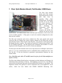
Moog Components Group
Fiber Optic Modem Rev. G
February 24, 2009
Fiber Optic Modem Board (with Diagnostics)
Part Number 200530-xxx
User’s Manual
And
Troubleshooting Guide
February 24, 2009
Rev. G
Moog Components Group
Springfield Operations
750 West Sproul Road
Springfield, PA 19064
E-Mail: [email protected] URL: www.moog.com/components
Tel: 610-328-4000 Fax 610-605-6216
24/7 Technical Customer Support Hotline: 610-605-6101
Page 1 of 14
Moog Components Group
1
Fiber Optic Modem Rev. G
February 24, 2009
Fiber Optic Modem Board, Part Number 200530-xxx ........................................................................... 3
1.1
Modem Board Revision History:.................................................................................................... 4
1.2
Modem Board Dash (-) Number Definitions:................................................................................. 6
1.3
Modem Board Operation: ............................................................................................................... 7
1.3.1
Modem Board Indicators and Connections: ........................................................................... 8
1.3.2
Modem Board Specifications: .............................................................................................. 10
1.3.3
Modem Board Dimensions: .................................................................................................. 10
1.3.4
Modem Board Power Requirements:.................................................................................... 10
1.4
Modem Board and Fiber Troubleshooting.................................................................................... 11
1.4.1
Board Level Testing ............................................................................................................. 11
1.5
Possible System Problems, Diagnosis and Fixes.......................................................................... 12
Page 2 of 14
Moog Components Group
Fiber Optic Modem Rev. G
February 24, 2009
1 Fiber Optic Modem Board, Part Number 200530-xxx
The Fiber Optic Modem
board sends and receives
digital data streams via fiber
optic links from an
opposing
Fiber
Optic
Modem board. The Modem
provides all of the timing
and control functions, the
high-speed link interface,
data
formatting
for
transmission, clock and
clock
recovery
for
reception, and parallel bus
interface for the rest of the
system boards. The Modem board comes with fiber optic transmitter (a laser device) and
receiver modules attached. 1.5Gbp optics is used in the standard configuration but other
data rates are available.
The fiber optic transmitter and receiver modules have fiber optic pigtails with optical
connectors that are plugged into optical couplers mounted on the board and set back
approximately 25mm (1 inch) from the front faceplate. The customer’s field optical cables
are plugged into these couplers. The couplers are typically ST single mode type but FC and
SC are available optionally. The fiber pigtail on the transmitter laser module is 9 micron
singlemode while the pigtail on the receiver is 50 micron multimode.
The fiber optic data link transmitter and receiver chips must have a full duplex connection in
place (i.e. two way communications must be established) before multiplexed data is sent
over the link. If only one direction is operational, synchronization characters are sent
instead of data.
Note: Both fiber optic cables (TX and RX) must be in place for the Prizm multiplexer to
operate correctly.
The Fiber Optic Modem Board has been re-designed to include hardware and firmware for
monitoring various parameters of interest. This capability is accessed via a 2 pin Phoenix
connector on the front panel that carries bi-directional RS-485 telemetry to the modem. The
diagnostics modem will typically be used in conjunction with a user-supplied PC on the
surface, which has been loaded with PRIZM MODEM Monitoring S/W.
Page 3 of 14
Moog Components Group
Fiber Optic Modem Rev. G
February 24, 2009
The diagnostics feature in no way interferes with normal operation of the modem – it is not
necessary to be running the diagnostics s/w for the modem to work. Communication with
the subsea modem is achieved through either a high-speed bit on the backplane or through a
RS-485 Submux channel on an available interface card. NOTE: A modem configured for
diagnostics over the backplane is NOT compatible with a modem that carries diagnostic
data across the optic link using a RS-485 Submux data channel.
In systems where the diagnostic data is carried over a high-speed bit on the backplane, it is
not necessary to wire to the 2-pin Phoenix connector on the subsea modem. Data is carried
from the 2-pin Phoenix connector on the surface modem, through the backplane and to the
subsea modem. Refer to the Diagnostic Modem Command Structure for External Interface
Users’ Manual for more details regarding the correct wiring scheme for specific
applications.
1.1 Modem Board Revision History:
The Modem board has gone through the following printed circuit board (PCB) and
Assembly revisions:
PCB Revision A/Assembly Revision A Original design.
PCB Revision A/Assembly Revision B Incorporates the following ECOs:
ECO20000620
Changed R75 value from 470 to 1K ohms
Added Voltage Ref IC0076 between R75 (right pad) and U19
pin 3
Added wire between U19 pin1 and T27
Added wire between R75 (right pad) and U28 pin 22
ECO20000710
Changed value of R42 from 470 to 4.7K ohms
Changed value of R41 from 1K to 10K ohms
Removed R54
Added wire from T22 to T31
Added wire to connect pins 4,5,6 & 7 on U30
ECO20000814
Changed Polarity of –5V led
ECO20000817
Removed R10, R14 and jumper JP11
PCB Revision A/Assembly Revision C Incorporates the following ECO:
ECO20001205B
Changed C27 and C30 from CS0065 to CS0080 to eliminate
field problems with interference when inserting card in rack.
PCB Revision A/Assembly Revision D Voided
PCB Revision A/Assembly Revision E Incorporates the following ECO:
ECO200530-002
Implemented multiple changes to improve RX Power
monitoring, add TX power monitoring, add packet error
monitoring and allow for interface with APD receivers.
Page 4 of 14
Moog Components Group
Fiber Optic Modem Rev. G
February 24, 2009
PCB Revision A/Assembly Revision F Incorporates the following ECO:
ECO200530-003
Disabled PER monitoring, removed shunt on Lattice.
PCB Revision A/Assembly Revision G Incorporates the following ECO:
ECO200530-004
Changed R13 and R58 from RS0137 to RS0169 to decrease
gain in the TX power monitoring circuit from 20:1 to 10:1
PCB Revision A/Assembly Revision H Incorporates the following ECO:
ECO200530-005
Changed U8 from IC0023 to IC0187 to increase stability of
clock drive at high temperatures.
PCB Revision B/Assembly Revision A Never released.
PCB Revision B/Assembly Revision B Original design.
Page 5 of 14
Moog Components Group
Fiber Optic Modem Rev. G
February 24, 2009
1.2 Modem Board Dash (-) Number Definitions:
The Modem board has several dash numbers appended to the part number. These dash
numbers identify specific board configurations:
-004 1.0Gbps, 1310 nm laser wavelength, ST optical connectors
-005 1.0Gbps, 1550 nm laser wavelength, ST optical connectors
-006 1.5Gbps, 1310 nm laser wavelength, ST optical connectors
-007 1.5Gbps, 1550 nm laser wavelength, ST optical connectors
-009 600Mbps, 1310 nm laser wavelength, ST optical connectors, 1G Optics
-010 600Mbps, 1550 nm laser wavelength, ST optical connectors, 1G Optics
-011 1.5Gbps, 1310 nm laser wavelength, ST optical connectors, SIMPLEX
-012 1.5Gbps, 1550 nm laser wavelength, ST optical connectors, SIMPLEX
-013 600Mbps, 1310 nm laser wavelength, ST optical connectors, 1.5G Optics
-014 600Mbps, 1550 nm laser wavelength, ST optical connectors, 1.5G Optics
-015 1.5Gbps, 1510 nm laser wavelength Laser (SC), APD Receiver optical connectors
-016 1.5Gbps, 1530 nm laser wavelength Laser (SC), APD Receiver optical connectors
-017 1.5Gbps, 1550 nm laser wavelength Laser (SC), APD Receiver optical connectors
-018 1.5Gbps, 1570 nm laser wavelength Laser (SC), APD Receiver optical connectors
-021 1.5Gbps, 1510 nm laser wavelength, ST optical connectors
-022 1.5Gbps, 1530 nm laser wavelength, ST optical connectors
-023 1.5Gbps, 1570 nm laser wavelength, ST optical connectors
-024 1.5Gbps, 1470 nm laser wavelength, ST optical connectors
-025 1.0Gbps, 1310 nm laser wavelength, ST optical connectors, Video 2
-026 1.0Gbps, 1510 nm laser wavelength, ST optical connectors, Video 2
-027 1.5Gbps, 1550 nm laser wavelength, ST optical connectors, APD receiver
-028 1.5Gbps, 1510 nm laser wavelength, ST optical connectors, APD receiver
-029 1.5Gbps, 1510 nm laser wavelength, ST optical connectors, diagnostics
through backplane
-030 1.5Gbps, 1550 nm laser wavelength, ST optical connectors, diagnostics
through backplane
-031 1.44Gbps, 1550 nm laser wavelength, ST optical connectors
-032 1.44Gbps, 1550 nm laser wavelength, ST optical connectors
-033 1.0Gbps, 1310 nm laser wavelength, ST optical connectors
-034 1.0Gbps, 1550 nm laser wavelength, ST optical connectors
-035 600Mbps, 1550 nm laser wavelength, ST optical connectors
-036 600Mbps, 1510 nm laser wavelength, ST optical connectors
-037 600Mbps, 1530 nm laser wavelength, ST optical connectors
-038 600Mbps, 1570 nm laser wavelength, ST optical connectors
Page 6 of 14
Moog Components Group
Fiber Optic Modem Rev. G
February 24, 2009
1.3 Modem Board Operation:
The Modem board interfaces to all the peripheral boards, as shown in the block diagram
below.
The transmit path is defined as the data flow direction from the peripheral boards over the
backplane to the Modem board for transmission over the serial link, to the remote system.
The receive path is from the remote system, through the modem, onto the backplane, to the
peripheral boards. When transmitting, the Modem board takes in all the various data and
video signals from the Prizm system’s peripheral boards and converts them to a single laser
generated light signal, which is transmitted to the Prizm system at the other end of the fiber
optic link. When receiving, the Modem board accepts the laser light signal from the other
end of the fiber optic link converts it back to the original data and video signals and directs
the reconstituted signals to the various peripheral boards in the Prizm system.
Modem board operation is not effected by the Diagnostics capability. Refer to the PRIZM
MUX Monitor User’s Manual for details concerning the set-up and use of the diagnostics
s/w package. Refer to the Diagnostic Modem Command Structure for External Interface for
details concerning the command structure required to communicate with the diagnostics
capability of the modem.
The Prizm Fiber Optic Video/Data Multiplexer Video 3 System is designed to carry video
and data signals over a fiber optic cable at distances of up to 20 kilometers at a link rate of
1.5 gigabits per second (Gbps). The function of the Multiplexer is to partition the total
system bandwidth into usable sub-bandwidths for use by the peripheral boards
Page 7 of 14
Moog Components Group
Fiber Optic Modem Rev. G
February 24, 2009
1.3.1 Modem Board Indicators and Connections:
There are six LED indicators on the front panel of the Modem board: +5,
-5, PWR, TEMP, LOC, and REM.
The green +5 LED (p/o LED1) indicates the +5 VDC status of the board
and is lit GREEN when +5VDC is available via the backplane.
The green –5 LED (p/o LED1) indicates the –5VDC status of the board
and is lit GREEN when -5VDC is available via the backplane.
The remaining LEDS are controlled via the on-board microcontroller
that is part of the diagnostics capability. If the microntroller fails the
status of these may not be indicative of actual status. NOTE: The
diagnostics feature in no way interferes with normal operation of the
modem – it is not necessary to be running the diagnostics s/w for the
modem to work.
The PWR LED (p/o LED2) indicates the +5VDC and –5VDC power
status of the board. It is GREEN when both the +5VDC and –5VDC are
within normal limits (absolute values from 4.9 to 5.2VDC), ORANGE
when either is within warning limits (absolute values from 4.8 to 4.9 and
5.2 to 5.3 VDC) and RED when either is outside the warning limits
(absolute values <4.8 or > 5.3).
The TEMP LED (p/o LED2) indicates the temperature status of the
board. NOTE: The Temperature sensor is currently physically located
next to the board heat sink and as such it is typically hotter (by about
12° Celsius) then the actual ambient temperature. It is GREEN when
the reading is below 72°C, ORANGE when between 72 and 77°C, and
RED when reading is 77°C and higher
The LOC LED (p/o LED3) is GREEN when the local receiver is
receiving valid data and it is an indication that the received power is of
acceptable level. This LED is RED when the local receiver is not
receiving valid data and is an indication of either too low received power
or receiver in saturation. The optical receiver has an operation range of
approximately –6dBm (saturation) to –25dBm (sensitivity); signal levels
that fall outside this range will result in invalid data and cause the LOC
LED to turn RED.
The REM LED (p/o LED3) provides an indication of the other ends LOC LED; it is
GREEN when the remote receiver is receiving valid data (received power is of acceptable
level) and RED when the remote receiver is not receiving valid data (too low received
Page 8 of 14
Moog Components Group
Fiber Optic Modem Rev. G
February 24, 2009
power or receiver in saturation). Obviously if the LOC LED is RED, the REM indication
will turn RED as well since no status from the remote unit will be received.
The 2-pin RT+/RT- connector provides the RS-485 connectivity to the on-board processor
for diagnostics communications. The initial release of the Diagnostics feature will require
that the user allow for the use of one RS-485 channel in the mutiplexer system for
connectivity between the topside Diagnostic PC and the remote multiplexer.
Two slots are cut in the faceplate to allow connection to the modem optical connectors (F/O
TX and F/O RX which are recessed behind the faceplate.
Page 9 of 14
Moog Components Group
Fiber Optic Modem Rev. G
February 24, 2009
1.3.2 Modem Board Specifications:
Link Data Rate:
System Frame Rate:
Link Options:
Fiber Options:
Fiber Wavelengths:
TX Optical Power:
RX Optical Power:
Link Lengths:
(Approximate)
600 Megabits/sec (Mbps) to 1.5 Gigabits/sec (Gbps)
25 Mega samples/sec (Msps) to 62.5 Msps
Fiber Optic
Singlemode or Multimode
1310, 1550 nanometers standard, other wavelengths available
0 dBm transmitter power output, typically
-25dBm receiver sensitivity
20 kilometers with singlemode at 1.5 Gbps
4 kilometers with multimode at 600 Mbps
1.3.3 Modem Board Dimensions:
VME 3-U printed circuit board (PCB):
100 mm wide x 160 mm long x 15 mm high (3.937 in x 6.299 in x .6 in)
VME 3-U PCB and faceplate in rack: 15 mm wide x 128 mm high (.6 in x 5.05 in)
1.3.4 Modem Board Power Requirements:
+5VDC at 2.0 Amps (10.0 Watts)
-5VDC at .1 Amps (.5 Watts)
Page 10 of 14
Moog Components Group
Fiber Optic Modem Rev. G
February 24, 2009
1.4 Modem Board and Fiber Troubleshooting
In normal operation all LED on the front panel should be green.
1.4.1 Board Level Testing
If either of the +5VDC or –5VDC LEDs are not lit:
(probably the other LEDs will not be lit as well)
Is this a total multiplexer problem or just this board?
o Verify status of power indicator LEDs on other boards
If other boards don’t have power, check Power Supplies
If other boards do have power, problem isolated to this board.
If problem is just this board.
o Verify Power at backplane connector
If Power is available, check for power on board across C30,
C31 or C32.
If Power on board, check LED and associated circuitry
If PWR LED is YELLOW or RED:
Verify board level power using Diagnostics s/w
Verify voltage readings at backplane and on-board
Adjust P/S as required
If TEMP LED is YELLOW or RED:
Verify temperature reading using Diagnostics s/w
If reading is verified to be at warning or alarm level, verify operation of
fans and observe adequate airflow through rack
If LOC LED and REM LED are RED :
Verify that fibers are connected properly
Verify Optical loss between remote TX and local RX
Verify that LOC LED does not turn green as fiber is removed from
receiver – if it does then receiver is saturating and an optical attenuator
will be required
Verify received power level using an optical power meter
Inspect all fiber optic connections including WDMs and sliprings.
If REM LED is RED and LOC is GREEN:
Verify transmitted power out of local modem
Verify that fibers are connected properly
Verify Optical Loss from Local TX to remote RX
Inspect all fiber optic connections including WDMs and sliprings.
Page 11 of 14
Moog Components Group
Fiber Optic Modem
February 24, 2009
Note: If the optical loss on the umbilical or test cable is TOO low (less than 1dB of
loss), place an optical attenuator (at least 3 dB but not greater than 20dB) on the
cable. The laser generates enough power to overdrive the optical receiver and
cause bit errors (red ERR LED may be lit or flickering) that can be confused with a
bad optical module or cable.
To determine if the fiber is broken, a laser module is out, or the modem is
malfunctioning, first:
• Verify that the optics are tight in their sockets and placed correctly.
• Verify that shunts (jumpers) are placed per system jumper configuration.
• Check all fiber optic connections including WDMs and sliprings to make sure that
they are not causing the problem.
• Check that the optical fiber cable is straight at connectors on Modem board for
minimum optic loss.
Then:
• Run a fiber optic loop back test as follows:
-
-
With these tests, you can determine if the problem is in the local Modem,
the remote Modem, laser optics, or the fiber cable itself. To perform the
tests, you need a known good length of fiber optic cable with connectors
on each end that are compatible with your Prizm system (typically ST
connectors)
Plug each Modem into its backplane and power up the systems
Place the known good fiber optic cable from the TX (Transmit) connector
to the RX (Receive) connector on the Modem board.
Note: Place an optical attenuator (at least 3 dB but not greater than 20dB) on the
cable. The laser generates enough power to overdrive the optical receiver and
cause bit errors (red ERR LED may be lit or flickering) that can be confused with a
bad optical module or cable.
-
1.5
Verify that the LOC and REM are both Green
o If not, MODEM module is suspect and should be replaced with a
spare.
Possible System Problems, Diagnosis and Fixes
Problem 1:
Diagnosis:
Fiber attached but LOC LED is RED or flickering RED.
The optical power may be barely sufficient for a good data link.
Check the receive fiber with an optical power meter; it should be in
the range of -6dBm to -25dBm at 1310 nM. If the power is too high,
it will be necessary to add an attenuator to reduce received signal
Page 12 of 14
Moog Components Group
Fix:
Problem 2:
Diagnosis:
Fix:
Problem 3:
Diagnosis:
Fix:
Problem 5:
Diagnosis:
Fiber Optic Modem
February 24, 2009
level. If the power is low, then the fiber cable may have a break or a
bad optical connector, or the laser transmitter at the other end of the
link may have failed. Test the optical output power of the laser at the
other end of the link, it should be at or above -10dBm at 1310 nM.
Connect the local laser transmitter directly to the local receiver with a
short length of optical cable, effectively "looping" the signal back on
itself. If the LOC and REM LEDs are lit, then the local receiver is
probably OK. Move to the other end of the link and repeat the steps.
If the local receiver or the remote laser appears bad, replace with a
spare Modem board.
Replace/repair fiber cable, optical connector or replace the Modem
board.
Fiber attached and LOC is GREEN but the REM LED is RED, no
video on ANY video channel.
Check the remote vehicle Modem status LEDs. The optical link
from the remote modem is probably out. If either the uplink or the
downlink has failed completely or the fiber is not connected (i.e.
LOC LED is RED), then the other link will be attempting to reestablish synchronization and sending sync characters instead of
data. The data link chips used in the Modem board requires a link in
both directions or a "loopback" link to operate correctly and carry
system data. Another possibility is the loss of the +5VDC or –5VDC
supply on the vehicle.
Connect both fibers and verify optical connections with LOC and
REM LEDs on at both ends of the link. Check Problem 1 above.
Verify the +5VDC and -5VDC power supply levels at the
backplanes.
No video signals on one or more of the video output channels.
Swap the cable on the problem channel with another working
channel at both video input and output. If the problem moves with
the cable, verify the cable integrity at both input and output with an
ohmmeter. If the problem is not a cable, first swap the Video Input
board with a spare one then swap the Video Output board with a
spare.
Replace/repair cable or Video board.
Telemetry link is lost at regular intervals or at regular intervals (i.e.
lost, reestablished, lost…).
If the ROV is on deck, shield the ROV unit of the Prizm system from
RF interference (radar). Make sure the control van door is shut to
shield the top side Prizm system from RF interference. If possible
turn off the ship’s radar system to prevent the Prizm system from
being swept by the radar.
Page 13 of 14
Moog Components Group
Fiber Optic Modem
February 24, 2009
Fix:
Shield Prizm system from radar generated RF interference.
Problem 6:
Telemetry link is lost or degraded video is experienced when ROV is
on deck.
The Prizm multiplexer may be overheating. While the components
on the multiplexer are rated to operate within the industrial
temperature range (0 degrees C to 70 degrees C), the fiber optic
component and especially the link ICs on the Modem board can fail
at temperatures above 70 degrees C. If the ROV telemetry bottle is
on deck and in the sun, temperatures inside the bottle can easily
exceed the systems operating temperature. The telemetry link will
reestablish itself when temperatures drop below 70 degrees C.
Keep the Prizm system within operating temperature range. When
on deck, keep the telemetry bottle shaded.
Diagnosis:
Fix:
Problem 7:
Diagnosis:
Fix:
Front Panel +5 and –5 LEDS are green, but all other front panel
LEDS are not lit.
Check power to the MODEM board. It is possible that the +5 and –5
LED can be lit at voltage levels below 5 volts. In this case the other
LEDs will not light because the low power level is not sufficient to
run the on-board processor.
Check multiplexer and diagnostics operation. If other then the LEDS
the multiplexer runs normally (passes video and data channels) but
diagnostics is not working, it is likely that the onboard diagnostics
processor is either disabled or not working.
Check the configuration of JP24 – for normal operation it should be
set in the 2-3 position. If it is in the 1-2 position the on-board
processor is disabled an diagnostics will not run.
If power supply is low, either adjust or replace.
If modem is operating normally but is not supplying diagnostics,
check configuration of JP24. If JP24 is configured correctly but still
no diagnostics, replace board.
If JP24 is configured to disable on board diagnostics processor, reconfigure for normal operation.
Page 14 of 14