1
Linker Reference Manual
by
John Diener and Andy Klumpp
ASH WARE, Inc.
Version 2.40
11/1/2015
(C) 2007-2015
page 2, Link er Reference Manual
Linker Reference Manual
Table of Contents
Foreword
5
Part 1 Command Line Options
Part 2 Code Location
7
21
2.1 Code
..............................................................................................................
Size
21
Part 3 Global Error Handling
23
3.1 Global
..............................................................................................................
Error Data
24
3.2 Error
..............................................................................................................
Handling Library
25
3.3 Invalid
..............................................................................................................
Entry Error Handling
25
3.4 In ..............................................................................................................
the SCM OFF Weeds Error Handling
26
3.5 In ..............................................................................................................
the FILL Weeds Error Handling
26
3.6 Unexpected
..............................................................................................................
Thread Error Handling
27
3.7 Extending
..............................................................................................................
the Error Handler
28
3.8 Accessing
..............................................................................................................
the Error Handler
28
3.9 Creating
..............................................................................................................
a User-Defined Error Handler
29
Part 4 Entry Table
33
4.1 Entry
..............................................................................................................
Table Base Address assignment
33
4.2 CFSR
..............................................................................................................
Assignment
33
Part 5 System Configuration Analyses
35
5.1 System
..............................................................................................................
Configuration File
35
Part 6 Channel Hardware Instruction
Packing
39
6.1 Channel
..............................................................................................................
Hardware Sub-Instruction Packing Convention
40
Link er Reference Manual, page 3
Linker Reference Manual
Part 7 Channel HW Sub-Instruction
Re-Ordering
43
Part 8 Linking Legacy (.COD) Code
45
8.1 Legacy
..............................................................................................................
Global Memory Allocation
45
8.2 Disabling
..............................................................................................................
optimization on legacy code
46
8.3 Legacy
..............................................................................................................
Code Limitations
46
8.4 Legacy
..............................................................................................................
Restrictions on ETEC
46
8.5 Legacy/ETEC
..............................................................................................................
Interactions
47
8.6 Legacy/ETEC
..............................................................................................................
Misc Notes
47
8.7 Auto-Header
..............................................................................................................
and Auto-Defines Information Validity
47
Invalid
.....................................................................................................................................
Legacy Auto-Header Inform ation
48
Supported
.....................................................................................................................................
ETPU_C Com piler Versions
48
Qualifying
.....................................................................................................................................
Unsupported eTPU_C Versions
48
Part 9 Optimization Limitations
49
9.1 Compiler/Optimizer
..............................................................................................................
Limitations
49
Com
.....................................................................................................................................
piler Inline Assem bly Lim itations
49
9.2 Assembly/Optimizer
..............................................................................................................
Limitations
50
Indeterm
.....................................................................................................................................
inate Return Value Lim itation
50
Hard-Coded
.....................................................................................................................................
Return Address Lim itation
50
Register
.....................................................................................................................................
Storage betw een Threads Lim itation
50
Invalid
.....................................................................................................................................
Construct Lim itation
51
Hard-Coded
.....................................................................................................................................
Value Lim itation
51
Multiply-Divide
.....................................................................................................................................
Unit (MDU) Lim itations
52
page 4, Link er Reference Manual
Linker Reference Manual
Link er Reference Manual, page 5
page 6, Link er Reference Manual
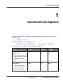
1. Command Line Options
1
Command Line Options
Type the executable name with the -h command line parameter to generate a list of the
available options.
ETEC_link.exe –h
The linker/optimizer has the following format:
ETEC_link.exe <ObjectFile1>
<ObjectFile2>
<options>
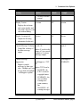
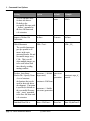
The <options> can be one or more of the following options.
Setting
Option
Default
Example
Display Help
-h
Off
-h
-man
Off
-man
This option overrides all
others and when it exists
no linking is actually
done.
Open Manual
Opens the electronic
version of this Linker
Reference Manual.
(C) 2007-2015
Link er Reference Manual, page 7
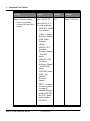
1. Command Line Options
Setting
Option
Default
Example
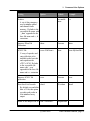
Open a Specific Manual
-man=<MANUAL>
Off
-man=ETPUCIM
Opens an electronic
version of the specified
manual.
where MANUAL is
one of the following:
TOOLKIT: Toolkit
User Manual.
COMP: Compiler
Reference Manual
LINK: Linker
Reference
Manual.
ASMFS: eTPU
Assembler
Reference Manual
- Freescale
Syntax.
ASMAW: eTPU
Assembler
Reference Manual
- ASH WARE
Syntax.
ETPUSIM: StandAlone eTpu
Simulator
Reference
Manual.
MTDT: Common
reference manual
covering all
simulator/debugger
products EXCEPT
the eTPU StandAlone simulator.
LICENSE:
page 8, Link er Reference Manual
(C) 2007-2015
1. Command Line Options
Setting
Option
Default
Example
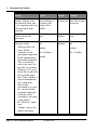
-version
Off
-version
-license
Off
-license
5
-verb=9
Off
-verbSuppress=
SUMMARY
License reference
manual
Display Version
Displays the tool name
and version number and
exits with a non-zero exit
code without linking.
Display Licensing Info
Outputs the licensing
information for this tool.
Console Message Verbosity -verb=<N>
Control the verbosity of
the linker message
output.
Console Message
Suppression
where N can be in the
range of 0 (no console
output) to 9 (verbose
message output).
verbSuppress=<TYP
E>
Suppress console
messages by their type/ where TYPE can be:
class. Multiple types can
BANNER : the
be specified with multiple
ETEC version &
–verbSuppress options.
copyright banner.
SUMMARY : the
success/failure
warning/error
count summary
line
WARNING : all
warning messages
(C) 2007-2015
Link er Reference Manual, page 9
1. Command Line Options
Setting
Option
Default
Example
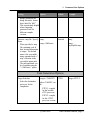
ERROR : all error
messages (does
not affect the tool
exit code)
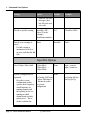
Disable a specific warning
-warnDis=<ID>
Off
where ID is the
warning's
identification number.
-WarnDis=41065
Strictly treat warnings as
errors
-Strict
-Strict
Disabled
If a link warning is
encountered, treat it as
an error such that the link
fails
Input File Options
List of Object Files to link
<ObjectFile1>
<ObjectFile2> ...
<ObjectFileN>
System Configuration File
(optional)
None
sysConfig=<FileName
> where FileName is
a file that describes
the system
configuration.
Describes system
configuration such as
system clock frequency,
which functions are
running channels and
their priority levels, etc.
running on which
channels and at which
priority level. This is
used to calculate the
page 10, Link er Reference Manual
(C) 2007-2015
None
etpuc_cam.eao
etpuc_crank.eao
sysConfig=MySyst
emCfg.SysCfg
1. Command Line Options
Setting
Option
Default
Example
-Imp=<name.cod>
None
-Imp=Existing.cod
-ImpData=<Bytes>
None
-ImpData=0x224
-ImpDataEnd=<byte
address>
None
ImpDataEnd=0x3F
0
Worst Case Latency
(WCL) based on the
Worst Case Thread
Length (WCTL).
Results are displayed in
the analyses file.
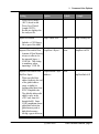
Import Executable
Includes a .COD legacy
file as part of the build.
Imported Executable Data
Amount of Data Memory
in bytes to allocate for
the imported legacy (.
COD) file. This setting
is mandatory when
importing a .COD file.
Imported Executable Data
End Free Space
When specified, this
address indicates the end
of the global address
range available for
locating global data from
ETEC-compiled code.
The globally addressable
address space in the
eTPU runs from 0x0
through 0x400. Some .
COD compilations locate
global data both in low
global memory and at
high global memory,
leaving a gap in between.
(C) 2007-2015
Link er Reference Manual, page 11
1. Command Line Options
Setting
Option
Default
Example
-ImpOpt-
Disabled
-ImpOpt-
-ErrorLib-
Enabled
-ErrorLib-
It is in these cases that
the use of -ImpDataEnd
is required; for most .
COD file imports it is not
required. For example, if
the imported .COD uses
the 3-byte unit at 0x3FD
as temporary storage,
and uses up through 0x55
in low global memory,
then the ideal linker
options would be "ImpData=0x58 ImpDataEnd=0x3FC".
Disable Imported
Executable Optimizations
Optimizations on the
imported legacy (.COD)
executable file default to
enabled. This option
overrides the default
such that optimizations
are disabled for imported
executables.
Disable Import of the
Default Error Handling
Library
When this option is
specified the default
error handling library is
not imported and the
memory fill is 0 unless
otherwise specified.
Once disabled, users can
page 12, Link er Reference Manual
(C) 2007-2015
1. Command Line Options
Setting
Option
Default
Example
provide their own error
handlers using the error
handler names
(_Error_handler_entry,
etc.).
Output File Options
Output File To Produce
Executable file name
None
out=<BaseFileName>
Suppress ELF/DWARF File -elfGeneration
Generate
Suppress Entry Table Debug -etdbgData
Generate
-out=MyOutputFile
Some consumers of ELF/
DWARF files may not
be compatible with the
entry table debug data;
this disables its output,
Output a global data
segment in the ELF/
DWARF file
-elfgd
Do not
-elfgd
output global
data segment
When this option is
specified a global data
segment is generated in
the ELF/DWARF file. It
has R/W attributes set,
and an alignment of 4
bytes.
Defines Header File To
Produce
-defines=<FileName> Based on
executable
(C) 2007-2015
defines=MyDefine
Link er Reference Manual, page 13
1. Command Line Options
Setting
Option
A set of #defines used
for host-side drivers.
Defaults to the
executable file name with
‘_defines’ appended to
the base file name and
a .h extension
Default
Example
name
sFile.h
Suppress Defines File
Generation
-defines-
Generate
-defines-
Global Mnemonic
-GM=<Text>
'-'
-GM=_FS_
auto-struct
file
generation
autostruct=etpu_if_
struct.h
Based on
idata=MyInitDataFi
The specified mnemonic
gets pre-pended to all
names in the autogenerated header file and
executable image array
C file. This is useful
when multiple images are
to be used at host load
time, thereby avoiding
naming conflicts.
Produce Auto-Struct
-autostruct // default
Header File / Specify Name (deprecated)
A set of structure
declarations that can be
used for host-side driver
development. If no name
is specified, it defaults to
the executable file name
with ‘_struct’ appended
to the base file name and
a .h extension
Initialized Data File to
page 14, Link er Reference Manual
autostruct=<FileName
>
-autostruct- // disable
auto-struct generation
-idata=<FileName>
(C) 2007-2015
1. Command Line Options
Setting
Option
Produce
A set of data structures
used to initialize global
and channel-frame
memory. Defaults to the
executable file name with
‘_idata’ appended to the
base file name and .c, .h
extensions.
Default
Example
executable
name
le.c
Suppress IData File
Generation
-idata-
Generate
-idata-
SCM C File
-scm=<FileName>
None
-scm=MyScmFile.c
Suppress SCM C file
generation
-scm-
Generate
-scm-
Data Size 8-bit Override
-data8
32-bit data
-data8
C array of opcodes and
entry table data to be
included on the host-side
and copied into the
eTPU’s SCM. Defaults
to the executable file
name with ‘_scm’
appended to the base file
name and a .c extension
By default, scm and idata
data is 32-bit; this option
overrides and results in
8-bit initialized array
output
Name of the analyses file to -ana=<FileName>
(C) 2007-2015
OutputFileBa -
Link er Reference Manual, page 15
1. Command Line Options
Setting
Option
Default
produce. Defaults to the
executable file name with
‘_ana’ appended to the base
file name and an .html
extension.
where FileName is
the name of the
analyses file to
product
seName.ana Ana=MyOverriden
tName.ana
Disable analysis file
generation
-ana-
Enabled
-ana-
Generate .lst files
-lst
Disabled
-lst
When specified, each
-lstInSrc
source file that
contributes to code
-lst=<DirName>
generation is output into a
-lstaddrlist file with intermixed
disassembly information.
They are named the
same as the source file
but with a .lst extension.
When just "-lst" is used,
the list files are placed in
the executable output
path. When "-lstInSrc" is
used each individual list
file is output in the
directory that
corresponds to its source
file. Last, the default
executable output path
for list files can be
overridden by specifying
a path with the "lst=<DirName>" option
form.
"-lstaddr-" removes the
address and opcode
page 16, Link er Reference Manual
(C) 2007-2015
Example
-lstInSrc
-lst=..\ListFiles\
1. Command Line Options
Setting
Option
Default
Example
Disabled
-map
listings which puts the
listing files into a format
that is ideal for "diff."
This is particularly helpful
when comparing
generated code for
different compiler
versions.
Generate .map file / Specify -map
Name
-map=<FileName>
When specified, a map
file containing code &
data location information
is output. The default
name is the executable
name appended with a ".
map" extension, in the
executable output path.
The path and name can
be overridden using the
"=<FileName>" option.
-map=..
\myMapFile.map
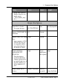
Code Generation Options
Target Selection
Select the destination
processor for the
compilation.
-target=<TARGET>
ETPU1
-target=ETPU2
where TARGET can
be:
ETPU1 : compile
for the baseline
eTPU processor.
ETPU2 : compile
for the eTPU2
processor version.
(C) 2007-2015
Link er Reference Manual, page 17
1. Command Line Options
Setting
Option
Default
Example
Entry Table Base Address
-etba=<Addr>
0x0
-etba=0x800
SCM Code Size
-CodeSize=<Bytes>
0x1800 (6K) -CodeSize=0x4000
Fill Opcode Override
-FillOpcode=<Val>
Jump to
error library
-FillOpcode=0x123
-opt-
Enabled
-opt-
Underlying architecture
supports only multiples of
0x800
Use specified opcode to
fill any unused SCM
code space
Disable optimizations
Optimizations default to
enabled. This option
overrides the default
such that optimizations
are disabled.
Network License Options
Retry Network License
-networkRetry=<N>
Off
-networkRetry=600
Check-out Network License Off
networkCheckout=<Y
Attempts to check-out a
networkCheckout=
If unable to acquire a full
license from the network
license server, the
application will continue
to re-try periodically up
to the specified number
of seconds until it
succeeds, or the retry
time expires.
page 18, Link er Reference Manual
(C) 2007-2015
1. Command Line Options
Setting
Option
Default
network license until the YYY:MM:DD:HH:
specified date and time. MM>
The HH field is in 24
hour time. No linking is
done, only the license
check-out. An exit code
of 0 indicates success,
non-zero failure.
Check-in Network License
-networkCheckin
Example
2010:08:04:18:00
Off
-networkCheckin
Returns a checked out
license to the network
license server. This only
needs to be done if the
license is being returned
before its checkout
expiration date. No
linking is done. An exit
code of 0 indicates
success, non-zero failure.
(C) 2007-2015
Link er Reference Manual, page 19
page 20, Link er Reference Manual
2. Code Location
2
Code Location
There is almost no reason at all for the user to care about code location so this section is
kind of like describing the difference between blue and red to a color blind person. Having
said that, code gets located beginning at address zero and continues upward.
The big issues are the entry table and “unbreakable code chunks”. An “unbreakable code
chunk” is a section of code that must remain contiguous in order to function properly and
the definition of “functioning properly” varies between the compiler and assembler. Entry
table locating is done first followed by code locating. If an “unbreakable code chunk”
would over-write the entry table, then it is moved in its entirety to the first available opcode
slot after the entry table.
ASH WARE reserves the right to change this algorithm, but in any case if you are doing
something that depends on the locating algorithm, then this author suspects you are doing
something wrong.
2.1
Code Size
Although the eTPU has a code space of 64K bytes, the various microcontrollers only
populate a portion of this. For instance, some eTPU derivates in the Coldfire family
populate 6K bytes and some eTPU derivatives in the MPC55xx family populate 12K.
To accommodate this variation in code size between the different eTPU derivates there is
a command line argument for specifying the amount of code space actually populated.
(C) 2007-2015
Link er Reference Manual, page 21
2. Code Location
This code size must be aligned to a 2K boundary, and must be between 2K and the
maximum code space allowed by the eTPU instruction set which is 64K.
page 22, Link er Reference Manual
(C) 2007-2015
3. Global Error Handling
3
Global Error Handling
A variety of causes including alpha particles, coding errors, and silicon defects could cause
eTPU code to execute in un-intended ways. The key issues to consider are error detection
and error correction.
Undetected errors are the bane of electronic reliability because the probability of their
presence accumulates over time, code size, hours spent coding, etc. Therefore ETEC
places primary emphasis on error detection and has built in hooks for detection of many
errors.
Error correction, on the other hand, is considered to be the in the user’s domain and ASH
WARE strongly recommends that each system designer carefully designs their systems
with error correction strategies in place. Having said that, ETEC does support “default”
error correction mechanisms. If these default mechanisms are not overridden, they will
correct a variety of detected error cases. The default error handling mechanism is
disabled or overridden by using the -ErrorLib- linker command line option.
ASH WARE recommends that users create specially-named error handlers for a variety
of possible error scenarios. These handlers are generally written in assembly, and have the
following names.
_Error_handler_entry.
_Error_handler_scm_off_weeds
_Error_handler_fill_weeds
_Error_handler_unexpected_thread
(C) 2007-2015
Link er Reference Manual, page 23
3. Global Error Handling
These error handlers should be used to correct the error conditions described later in this
section.
3.1
Global Error Data
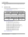
If an error is detected, information helpful in diagnosing the source of the error is placed in
an automatically-generated global variable named as follows:
_Global_error_data.
This 32-bit variable is used to encode error information as shown in the following table.
31
30
29
28
27
26
25
24
23
22
21 20 19 18 17 16
EESB
15
14
13
12
11
10
EEEVS
Spare
9
8
7
6
5
4
EECL
3
2
EECN
EESB – Encoded Error Source Bits
Bit = 1 indicates that such an error has been detected
Bit = 0 indicates that such an error has not been detected.
Bit 31 indicates that _Error_handler_entry has executed.
Bit 30 indicates that _Error_handler_scm_off_weeds has executed.
Bit 29 indicates that _Error_handler_fill_weeds has executed.
Bit 28 indicates that _Error_handler_unexpected_thread has executed
Bit 27 indicates that undefined ETEC error 2 has occurred
Bit 26 indicates that undefined ETEC error 3 has occurred
Bit 25 indicates that user-defined error 1 has occurred
Bit 24 indicates that user-defined error 2 has occurred
Bit 23 indicates that user-defined error 3 has occurred
Bit 22 indicates that user-defined error 4 has occurred
EEEVS – Encoded Event States
page 24, Link er Reference Manual
(C) 2007-2015
1
0
3. Global Error Handling
Bit = 1 indicates that an event is active
Bit = 0 indicates that an event is not active
Bit 15 contains the LINK state
Bit 14 contains the Transition B state
Bit 13 contains the Transition A state
Bit 12 contains the Match B state
Bit 11 contains the Match A state
Bit 10 contains zero (future expansion)
Bit 9 contains zero (future expansion)
EECL – Encoded Error Conditionals
Bit 8 contains the sampled input pin state
Bit 7 contains the current output pin state
Bit 6 contains the flag 1 state, if available
Bit 5 contains the flag 0 state, if available
EECN - Encoded Error Channel Number
This is the active channel number of the last event handler. New incoming event handlers
overwrite this value such that if error handlers are executed multiple times, then the
number contains the last-executed time.
3.2
Error Handling Library
The ASH WARE defined error handlers are defined in a library named
“etec_error_handler.lib (for eTPU1) and etec_error_handler_etpu2.lib (for eTPU2) which
is provided as part of ETEC. The linker automatically includes one of these two libraries
based on whether the linker is building for eTPU1 or eTPU2.
The error handling library can be disabled from being included in the linking process via the
-ErrorLib- command line option.
3.3
Invalid Entry Error Handling
Threads get executed based on pointers found in the entry table. The entry table supports
up to 32 functions but it is rare to actually use all 32 functions. The unused entries are
considered to be invalid and in normal operation would never get accessed.
(C) 2007-2015
Link er Reference Manual, page 25
3. Global Error Handling
It is an error to access an unused function in the entry table. When possible, unused
entries are filled with the following address.
_Error_handler_entry.
It is not always possible to fill unused entries with this address because unused portions of
the entry table can be used to hold code. So this address is used where the entry table
contains neither eTPU functions nor eTPU code.
3.4
In the SCM OFF Weeds Error Handling
The address space of the eTPU is 64K, but Freescale generally only fills a very small
portion of this code space with physical memory. For example, the very first MPC5554
version had only 12K of code memory. So what happens if, due to an error, the thread of
execution should occur in the unused 52K of code space?
It is an error to execute from the unused portion of the SCM code memory and when this
happens the actual opcode that gets executed is specified by the SCMDATAOFFR
register. ETEC provides an SCMDATAOFFR register value (see the
SCM_OFF_OPCODE #define in the auto-defines header section) that will cause the
following error handler to execute.
_Error_handler_scm_off_weeds
Note that this error handler will only execute if the #define SCM_OFF_OPCODE <value>
provided in the automatically-generated header file is used to program the
ETPUSCMOFFDATAR register.
3.5
In the FILL Weeds Error Handling
Say you have 18K of available code memory but use only 15K. The remaining 3K of code
memory is essentially spare capacity. So what happens if the thread of execution
somehow moves to this extra 3K of code memory?
It is an error to execute from this spare memory. ETEC defaults to filling this spare
memory with a jump to the error handler listed below. Note that a jump is used instead of
a call so that the user can possibly determine an address (based on the return address
register, RAR) of any possible originating return that might have caused this code to get
executed in the first place.
_Error_handler_fill_weeds
page 26, Link er Reference Manual
(C) 2007-2015
3. Global Error Handling
A related issue is the fill opcode specified on the command line. If a fill-opcode value is
specified on the command line then this overrides the default fill opcode that ETEC would
have used to jump to this error handler. It is therefore an error to both specify a fill opcode
and to override this error hander, and in fact if a fill opcode is specified then ETEC will
neither provide, nor allow, this error handler to exist.
3.6
Unexpected Thread Error Handling
Say you have a function that does not support an incoming link event. If a link does occur
this is an error condition and should be made observable to the host software so that the
problem does not remain undetected. The 'Unexpected Thread' error handler can be used
both in ETEC mode and legacy mode 'C' as well to detect these types of unexpected
errors. Note that no overhead is incurred using the methods described below. The
address of the error handler is injected directly into the entry table.
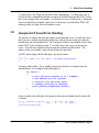
In ETEC mode simply add the following to any unused entries.
< . . . >
5 | X | X | X | input=X | X | X | low | enable | ::_Error_handler_unexpected_thread
< . . . >
In Legacy mode call the _Error_handler_unexpected_thread as a fragment from any
unused threads. For example, do the following for t
if( hsr==1 )
{
// Call the error handler as if a fragment
// The address will be injected
// directly into the entry table
// thereby incurring no overhead
_Error_handler_unexpected_thread();
}
In the assemble entry table place the unexpected thread error handler directly in the table
as follows.
hsr | lsr | transitionB | transitionA | pin
1 | X |
X
|
X
| input=0
_Error_handler_unexpected_thread
| flag1 | flag0 | load | matches |
|
X
|
0
| low | enable | ::
(C) 2007-2015
Link er Reference Manual, page 27
3. Global Error Handling
3.7
Extending the Error Handler
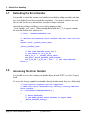
It is possible to extend the custom error handler in assembly by adding assembly code that
uses 'user-defined' error bits to extend the error library. Care must be taken to use error
bits set aside for the user, and not those set aside for future extension.
Note that the existing error library is accessed by jumping to label
'_Error_handler_save_states'. When entering this location the P_31_0 register contains
the error bits that the user wishes to set.
// File:
UserErrorHandler.sta
// declare the external error handler data bit that will be
set
extern int32 _Global_error_data;
_Error_handler_user:
// Set user-defined error bit 2
// and leave it in p_31_24
ram p_31_0 = _Global_error_data;;
seq goto _Error_handler_save_states;;
alu p_31_24 = p_31_24 | 0x1;; // Set user-defined
error 2
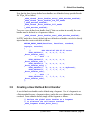
3.8
Accessing the Error Handler
It is possible to access the existing error handler library in both 'ETEC' as well as 'Legacy'
mode.
To access the factory-supplied error handlers directly in either mode, they are called suchly
// Link service requests are not supported
// Make this error observable by calling a factory-defined
error handler
if ( IsLinkServiceRequestEvent() )
{
// Error Detected,
// the ETEC global error handler in etpuc mode
_Error_handler_entry();
}
page 28, Link er Reference Manual
(C) 2007-2015
3. Global Error Handling
Note that the three factory-defined error handlers are defined in factory-provided header
file 'ETpu_Lib' as follows
_eTPU_thread _Error_handler_entry(_eTPU_matches_enabled);
_eTPU_thread _Error_handler_scm_off_weeds
(_eTPU_matches_enabled);
_eTPU_thread _Error_handler_fill_weeds
(_eTPU_matches_enabled);
To access a user-defined error handler from 'C' that was written in assembly, the error
handler must be declared as a fragment as follows.
_eTPU_thread _Error_handler_user(_eTPU_matches_enabled);
In ETEC mode these factory-defined and user-defined error handlers can also be directly
injected into the event vector table as follows.
DEFINE_ENTRY_TABLE(TestClass, TestClass, standard,
inputpin, autocfsr)
{
//
HSR LSR M1 M2 PIN F0 F1 vector
ETPU_VECTOR1(1, x, x, x, 0, 0, x,
_Error_handler_user),
<... SNIP ...>
ETPU_VECTOR1(5, x, x, x, x, x, x,
_Error_handler_user ),
ETPU_VECTOR1(6, x, x, x, x, x, x,
_Error_handler_entry ),
ETPU_VECTOR1(7, x, x, x, x, x, x, MyThread),
ETPU_VECTOR1(0, 1, 1, 1, x, 0, x,
_Error_handler_user),
<... SNIP ...>
ETPU_VECTOR1(0, 1, 1, 0, x, 1, x,
_Error_handler_user),
};
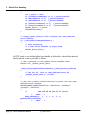
3.9
Creating a User-Defined Error Handler
A user defined error handler can be defined using a fragment. Use of a fragment is an
efficient method because a fragment reduces (and in this case eliminates) the call/return
overhead. From within the thread, simply call the fragment as follows.
// Declare the global error handler as a fragment
// to eliminate the call/return overhead
_eTPU_fragment Global_Error_Func()
(C) 2007-2015
Link er Reference Manual, page 29
3. Global Error Handling
{
int l_error = chan;
if (LinkServiceRequest == 1) l_error+=0x0100;
if (MatchALatch == 1) l_error+=0x0200;
if (MatchBLatch == 1) l_error+=0x0400;
if (TransitionALatch == 1) l_error+=0x0800;
if (TransitionBLatch == 1) l_error+=0x1000;
Global_Error = l_error;
ClearAllLatches();
}
// Legacy mode function that accesses the user-defined
error handler
if ( IsLinkServiceRequestEvent() )
{
// Test accessing
// a user error handler in etpuc mode
Global_Error_Func();
}
In ETEC mode, a user-defined global error handler is declared as a thread, then inserted
directly into the event vector table as follows.
// Get a pointer to the global error handler data
extern int _Global_error_data;
_eTPU_thread MyGlobalErrorHandler(_eTPU_matches_enabled)
{
// Set bit 22, this is user-defined error #2
_Global_error_data |= (1<<22);
}
// Set one or more invalid entries to point the the userdefined error handler
DEFINE_ENTRY_TABLE(TestClass, TestClass, standard,
inputpin, autocfsr)
{
//
HSR LSR M1 M2 PIN F0 F1 vector
<... SNIP ...>
ETPU_VECTOR1(0, 1, 1, 1, x, 0, x,
MyGlobalErrorHandler),
<... SNIP ...>
};
page 30, Link er Reference Manual
(C) 2007-2015
3. Global Error Handling
(C) 2007-2015
Link er Reference Manual, page 31
page 32, Link er Reference Manual
4. Entry Table
4
Entry Table
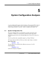
This section covers the entry table.
4.1
Entry Table Base Address assignment
There is a command line argument for specifying the entry table base address. The eTPU
architecture forces the entry table base address to be on a 2K boundary. Additionally, the
entire entry table must be located within the boundaries of the amount of code actually
populated in the eTPU derivate.
4.2
CFSR Assignment
Each entry table is assigned a CFSR register value. Although this can be done by the user
in the compiler and assembler, it is generally preferable to allow the linker to assign CFSR
values.
This section describes how un-assigned CFSR values are assigned. Although this section
might seem interesting, especially to those who enjoyed the math portion of the SAT,
specifics of this algorithm should not be counted on by the user. In fact, ASH WARE
reserves the right to change this algorithm with future linker releases. Use the autodefines capability to determine which CFSR value the linker has actually assigned to each
entry table.
(C) 2007-2015
Link er Reference Manual, page 33
4. Entry Table
The linker assigns un-assigned CFSR values using the algorithms described here. The
specific algorithm used depends on whether or not the entry table base address is at
address zero (the default) and if there are any user-assigned CFSR values. The intent of
this algorithm is to reduce the number and size of gaps in the entry table, thereby improving
the code packing efficiency.
If the entry table is located at address zero and there are no user-assigned CFSR values
then CFSR assignment begins with zero, and continues with progressively higher numbered
values.
If the entry table is NOT located at zero and there are no user-assigned CFSR values then
assignment begins with 31, and continues with progressively lower numbered values.
If the entry table is located at address zero but there are user-assigned CFSR values, then
the linker assigns CFSR values starting with the highest numbered value, and assigns
progressively lower numbered values until zero is reached. Then progressively higher
numbered values are assigned
If the entry table is NOT located at zero and there ARE user-assigned CFSR values, then
CFSR values assignment begins with the lowest user-assigned CFSR value and continues
upwards to 31. Then progressively lower numbered values are assigned
page 34, Link er Reference Manual
(C) 2007-2015
5. System Configuration Analyses
5
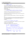
System Configuration Analyses
A system configuration file supports advanced analyses of the generated eTPU code in an
actual system. System parameters such as system clock speed, channel priorities, and
channel assigned functions are specified. Results are displayed in the analyses. file.
5.1
System Configuration File
The system configuration file is a text file that the user edits to specify the system
configuration. The linker uses the information contained in this file along with the
functional parameters in the code to determine things such as Worst Case Latency for a
channel.
The file is specified on the command line using the -sysConfig=<FileName>.
The format is line based which each line may contain a single setting, or acomment.
Ram Collision Rate
<PERCENT>
RCR
The ram collision rate is specified by the collision rate, in percent (0 to 100.)
Clock Frequency
<FREQUENCY> mhz
System clock frequency in megahertz.
(C) 2007-2015
Link er Reference Manual, page 35
5. System Configuration Analyses
Processor Family
<PROCESSOR FAMILY>
Processor family. Valid values are MCF (Coldfire,) MPC (Freescale Power
Architecture,) or SPC (STMicro Power Architecture.) Note that the Freescale and
STMicro power architectures both take two system clocks to execute one eTPU
instruction. In the Coldfire architecture each eTPU instruction takes four system clocks to
execute, OUCH!
Channel Configuration
<Engine> <CHANNEL> <FUNCTION> <PRIORITY> <MAX_WCTL>
ENGINE is the engine of the channel being specified, valid values are A and B.
CHANNEL is the channel number being specified, valid range is 0 to 31.
FUNCTION is the name of the eTPU Function for legacy style code or the name of the
eTPU Class for ETEC style code.
PRIORITY is the priority assigned to that channel. Valid values are 'high;, 'middle' and
'low'.
MAX_WCTL is an optional parameter that specifies that maximum allowed Worst Case
Thread Length (WCTL) in micro-seconds. The link will fail if the calculated WCTL
exceeds this specified maximum.
Comments
// This is an example C style comment
Comment lines using a leading double slashes. Empty lines are also treated as comments.
Example System Configuration File
The following is an example of a system configuration file.
25
133
MPC
RCR
mhz
// RAM collision rate (percent)
// System clock frequency
// Freescale Power Architecture
// - In engine A, the LOW priority is longer than the
MIDDLE
//
So latency is 1 low + 1 high (shorter MIDDLE not
used)
// Engine Channel Function Priority MaxWCL
(microseconds)
A,
3,
UART,
high,
0.95
page 36, Link er Reference Manual
(C) 2007-2015
5. System Configuration Analyses
A,
A,
4,
5,
PWM,
PWM,
middle,
low,
// - In engine A, the LOW priority is longer than the
MIDDLE
//
So latency is 1 low + 1 high (shorter MIDDLE not
used)
// Engine Channel Function Priority MaxWCL
(microseconds)
B,
3,
QOM,
high,
1.40
B,
4,
UART,
middle,
B,
5,
UART,
low,
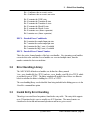
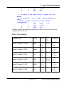
The linker generates the following information in the analyses file based on the System
Configuration file listed above.
Worst Case Latency
Channel/Function
Priority
WCTL*
Max
WCL
Actual WCL
Engine A, Channel 3, UART
High
0.56 us
(30,14)
0.95 us
0.86 us
(45,20)
Engine A, Channel 4, PWM
Middle
0.30 us
(15,6)
-
1.97 us
(105,48)
Engine A, Channel 5, PWM
Low
0.30 us
(15,6)
-
3.64 us
(195,90)
Engine B, Channel 3, QOM
High
0.76 us
(43,17)
1.40 us
1.32 us
(73,31)
Engine B, Channel 4, UART
Middle
0.56 us
(30,14)
-
2.85 us
(159,65)
Engine B, Channel 5, UART
Low
0.56 us
(30,14)
-
5.14 us
(288,116)
(C) 2007-2015
Link er Reference Manual, page 37
5. System Configuration Analyses
Note: WCTL (Worst Case Thread Length) includes the Steps, RAM's, TST's (Time
Slot Transitions) and TST-RAM's with RCR (RAM Collision Rate) factored in. The two
numbers in parantheses are the instruction-steps and the RAM's
Configuration
System clock frequency: 133 MHz
Ram Collision Rate (RCR): 25%
Processor family: 'Freescale Power Architecture'
page 38, Link er Reference Manual
(C) 2007-2015
6. Channel Hardware Instruction Packing
6
Channel Hardware Instruction
Packing
This section describes the most important improvement of this tools suite over other options
and the capabilities described are the primary motivating factor behind the development of
this compiler (that and income of course.) Consider the following sub-instructions.
chan clear MatchRecognitionLatchA;;
chan matchA = ertA, set MatchEnableLatchA;;
It turns out that the parallel nature of the eTPU’s instruction set allows these subinstructions to be packed into a single opcode. But it is also possible that these subinstructions could be placed into separate opcodes and the trouble is that the eTPU’s
channel hardware behavior is vastly different depending on which way the optimizer packs
these sub-instructions. The combination of lack of control and lack of documentation has
driven this author into a state of apoplectic perdition for the last several years.
ETEC addresses this issue in two ways, one is really good (user-control), and one is, well,
kinda good (Convention Documentation.) These are described in the following two
sections.
(C) 2007-2015
Link er Reference Manual, page 39
6. Channel Hardware Instruction Packing
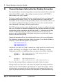
6.1
Channel Hardware Sub-Instruction Packing Convention
The channel hardware sub-instruction packing convention documented in this section is the
default for the ETEC compiler. This packing convention is based on ASH WARE’s
understanding of the legacy compiler.
The legacy compiler packed channel hardware sub-instructions based on an (apparently)
un-documented convention. That is to say, the packing scheme was (apparently) not
documented, but the convention would (presumably) stay the same from one release to the
next such that code that functioned in a particular way in one release would retain that
same functionality if built using a different compiler release.
The ETEC packing convention can be disabled using the #pragma no_packing_convention
and, in fact, the author recommends disabling the packing convention and instead explicitly
specifying the packing constraints as described in section 5.1, “Sub-Instruction Packing
Control.” Explicitly specifying the packing constraints both reduces code size and
increases your own understanding of the quality-critical issues associated with channel
hardware sub-instruction ordering.
Channel sub-instructions that are located adjacently in source code are packed together.
This definition is ambiguous, and requires further description. To see that the definition is
ambiguous, consider the following three sub-instructions.
Sub Instruction A;;
Sub Instruction B;;
Sub Instruction C;;
Consider the case where A, B, and C cannot fit into a single opcode, but A and B can fit
together, and B and C can fit together as well. Either of the following two packing
combinations satisf the over-simplified packing convention as described up to this point.
Opcode 1:
Opcode 2:
Sub Instruction A + Sub Instruction B;;
Sub Instruction C;;
Opcode 1:
Opcode 2:
Sub Instruction A;;
Sub Instruction B + Sub Instruction C;;
Or, …
Therefore, the packing definition is ambiguous and requires further description.
Starting from the top of the source code (lowest line number) and working towards the
bottom of the file, channel hardware sub-instructions are packed into opcodes. When a
sub-instruction is encountered that will not fit into the opcode being packed, then a new
opcode is generated and newly-encountered sub-instructions are packed into this newly-
page 40, Link er Reference Manual
(C) 2007-2015
6. Channel Hardware Instruction Packing
generated opcode.
This packing convention only applies to channel hardware sub-instructions and only to
those sub instructions with ordering dependencies. The following sub-instruction fields are
specifically excluded: FLC and CIRC.
These packed opcodes may experience some movement (to reduce code size) but in all
cases the movement will not result in any functional variation except as noted elsewhere in
the documentation.
With this fully-defined description, ONLY the following packing order can occur.
Opcode 1:
Opcode 2:
Sub Instruction A + Sub Instruction B;;
Sub Instruction C;;
To summarize, the key points presented in this section are as follows:
For optimal quality, reduced code size, and full understanding of your code’s
behavior, it is best to disable the packing convention described in this section,
and instead fully specify the packing order as described in the section 5.1,
“Sub-Instruction Packing Control.”
The packing convention defined in this section has been adopted to maximize
backward compatibility with the legacy compiler. The author recommends
not relying on the legacy packing convention.
The legacy packing convention applies ONLY to channel hardware subinstructions.
(C) 2007-2015
Link er Reference Manual, page 41
page 42, Link er Reference Manual
7. Channel HW Sub-Instruction Re-Ordering
7
Channel HW Sub-Instruction
Re-Ordering
The CIRC field is considered to be independent of all other channel hardware fields. It
can be re-ordered with no restrictions. It is restricted relative to RAM operations though.
It cannot pass any RAM operations. Once in the same instruction as a RAM, it cannot be
re-ordered.
The FLC field has no re-ordering restrictions whatsoever.
The LSR field has no re-ordering restrictions whatsoever. (It is tied to the TST channel,
not the channel register)
MRL and ERW form “blocks” relative to the following fields; OPAC, IPAC, TDL, TBS,
PSC, PSCS, MRLE, PDCM, PDCM, and MTD. If MRL and ERW are upstream, then
they cannot join with these fields. Conversely, if these fields are upstream then they CAN
join with these fields.
(C) 2007-2015
Link er Reference Manual, page 43
page 44, Link er Reference Manual
8. Linking Legacy (.COD) Code
8
Linking Legacy (.COD) Code
ETEC supports linking existing legacy mode eTPU code (.COD) along with object files
generated by the ETEC tools chain (assembly and “C” source.) This capability allows
users to migrate to the ETEC tools suite in a gradual manner.
8.1
Legacy Global Memory Allocation
Global memory is normally associated with global variables but the legacy compiler also
uses global memory to store values across function calls, to pass function call variables,
and for dynamic local variables that overflow the register set.
The issue (unfortunately) is that there is no reliable way of determining the amount of
global memory that is used by the legacy compiler, and ETEC (unfortunately) requires that
you pass this value to the ETEC linker via the command line (-ImpData). In fact, global
memory allocation is even more complicated than that in some cases because at times a .
COD compilation also uses high global memory just below address 0x400, typically for
temporary storage. When this split global locating occurs in the .COD file to imported, the
lower bound of this upper section of data must also be specified (-ImpDataEnd). This
allows ETEC to safely locate its global variables from ETEC-compiled object files into the
empty range. See the command line options section for a description of how to specify the
amount of global memory to allocate for legacy compiler generated (.COD) code.
(C) 2007-2015
Link er Reference Manual, page 45
8. Linking Legacy (.COD) Code
8.2
Disabling optimization on legacy code
Optimizations on legacy code default to enabled. When enabled the entry table will likely
change to adjust address pointers to the size-reduced code and to optimize preloads.
Opcodes may change some due to optimization, though unchanged opcodes will have a bias
toward retention of their original packing.
Optimizations for the imported legacy code (.COD) can be disabled, see the command line
options for a description of how this is done. With optimizations disabled the entry table
and executable portions of the code image remain unchanged, though any “dead space”
between the entry table and code will use the ETEC fill algorithm.
The ETEC optimizer makes assumptions about code behavior and certain legacy-compiler
features may violate these assumptions such that the ETEC optimizer should not be
enabled legacy-compiler generated code. The following is a list of the known features
*
8.3
Register allocation to global or static variables. (The ETEC optimizer
assumes that registers need not retain their value across threads.)
Legacy Code Limitations
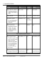
The following restrictions apply to the legacy compiler generated code.
*
*
*
*
8.4
The entry table must be located at address zero (the normal default)
Only COD compiler versions (TBD) are supported.
Enabling of optimizations for legacy-generated code may invalidate any
legacy auto-generated code.
The .COD’s fill opcode is ignored and the ETEC fill algorithm is used
instead.
Legacy Restrictions on ETEC
Linking with legacy compiler generated code places some restrictions on the ETEC
generated code that can be linked.
*
*
*
The entry table must be located at address zero
ETEC-generated code cannot specify a function number that is used by the
legacy-compiler generated code.
There must be a gap between the end of the legacy generated entry table
and the start of legacy-generated code into which the ETEC-generated
entry table gets placed (TBD: Can we relocate the BC-generated code??)
page 46, Link er Reference Manual
(C) 2007-2015
8. Linking Legacy (.COD) Code
When compiling the legacy code, use the legacy “org” statement to generate
this gap.
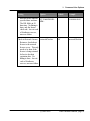
8.5
Legacy/ETEC Interactions
Some interactions between the legacy compiler generated code and ETEC generated code
are allowed, as listed below.
Certain types of (generally simple) global variables declared in legacy-generated code can
be accessed by ETEC generated code. These include the following
*
*
8.6
int24, unsigned int24, int8, unsigned int8, int32, unsigned int32 (global)
int, unsigned int, char, unsigned char.
Legacy/ETEC Misc Notes
* Analyses files are valid for etec generated code
* Disable optimizations on the legacy-generated code to retain validity of certain legacy
#pragma writes (auto header)
* In many cases the legacy code’s
* The ETEC-generated auto-defines file is valid. In certain cases, the legacy-generated
auto-header must not be used. For example the
8.7
Auto-Header and Auto-Defines Information Validity
Auto-header files are generated by the legacy compiler and auto-defines files are
generated by the ETEC compiler. In all cases, information in the ETEC-generated autodefines file is valid. The safest route is simply to switch to the ETEC-generated autodefines file, but this may not be an option for all customers. This section describes which
information from the legacy-generated auto-header can still be used.
Information in the legacy-generated auto-header may or may not be valid depending on the
nature of the information and on whether or not optimizations are enabled for the legacy
generated code.
(C) 2007-2015
Link er Reference Manual, page 47
8. Linking Legacy (.COD) Code
8.7.1
Invalid Legacy Auto-Header Information
The following list represents information in the legacy-generated auto header that are not
valid.
*
*
*
8.7.2
The code block
MISC value
Global Data Size
Supported ETPU_C Compiler Versions
The following is a list of supported versions at the time of this printing. See our website for
the most up-to-date list.
*
1.0.7.55
Note that unsupported compiler versions will in all likelihood still work. If the version of the
compiler that you are using is not on the supported versions list, please contact ASH
WARE for support of your compiler version.
8.7.3
Qualifying Unsupported eTPU_C Versions
Although code generated by unsupported eTPU_C compiler versions will generally
function when imported, it is possible to qualify unsupported versions using the process
described in this section.
The key issue in the qualification process is that not all eTPU_C compiler versions are
available to ASH WARE. Therefore, to qualify your eTPU_C compiler version, the
following process has been established. (TODO=develop a standard test suite)
Customer requests ASH WARE to support a specific eTPU_C compiler
version.
ASH WARE provides customer with a test build suite
Customer builds the test suite and provides ASH WARE with the resulting .
COD file.
ASH WARE adds the .COD file to the ETEC test suite and (assuming it
passes all tests) adds this .COD version to the list of supported compilers.
page 48, Link er Reference Manual
(C) 2007-2015
9. Optimization Limitations
9
Optimization Limitations
This section covers optimization limitations.
9.1
Compiler/Optimizer Limitations
The Return Address Regester (RAR) cannot be written within a called “C” function. For
instance, the following construct is not allowed.
MyCFunc()
{
rar = <SomeNumber>.
}
9.1.1
Compiler Inline Assembly Limitations
The limitations for inline assembly are the same as those listed in the assembly limitations
section.
(C) 2007-2015
Link er Reference Manual, page 49
9. Optimization Limitations
9.2
Assembly/Optimizer Limitations
There are quite a few optimizer limitations to assembled code, however these limitations
are all detected by the optimizer such that the optimizer will detect and report any
constructs that prevent optimization. Detected constructs that prevent optimization result in
the optimize/link stage being abandoned and such that no invalid code is generated.
9.2.1
Indeterminate Return Value Limitation
The optimizer needs to fully understand all possible paths and this is not possible when the
RAR register has an un-initialized or otherwise indeterminate value. For instance, the
following constructs causes the optimization to fail because the RAR register value is
unknown at the time of the return.
ThreadStart:
seq return;;
The following construct also causes the optimizer to fail for the reason that if the call is not
taken then the RAR register is un-initialized.
ThreadStart:
seq if n == false then call MyFunc, flush;;
seq return;;
9.2.2
Hard-Coded Return Address Limitation
The optimizer does not support code that hardcodes the return address. Any writes to the
return address register using an ALU instruction is not supported. An example of an
unsupported construct is found below
alu
ReturnAddr = b;;
Please contact the factory for hints on overcoming this limitation.
9.2.3
Register Storage between Threads Limitation
It is not possible to store global static variables in registers such that their value remains
valid between threads. The optimizer assumes that all registers begin each thread with
garbage data, and that any final register writes at the end of a thread are garbage.
ThreadStart:
page 50, Link er Reference Manual
(C) 2007-2015
9. Optimization Limitations
Seq diob = diob + 1;;
count
Seq end;;
// Diob contains the thread
In the above case the optimizer does not see the diob register value getting used between
the increment and the end of the thread and therefore will eliminate the opcode.
9.2.4
Invalid Construct Limitation
If the Freescale lists a construct as being invalid then use of the construct will cause the
optimizer to fail. For instance, a un-flushed seq followed by an flushed seq results in
indeterminate eTPU operation per the Freescale documentation.
seq goto MyFunc1, no_flush;;
seq goto MyFunc2, flush;;
Another invalid construct per the Freescale documentation is the destination of the first of
two sequential un-flushed branches being another change-in-flow instruction. For example,
use of the following construct will cause the optimizer to fail because the first opcode in the
called function is a change-of-flow.
MyFunc1:
seq return, flush ;;
ThreadStart:
seq goto MyFunc1, no_flush;;
seq goto MyFunc2, no_flush;;
< . . . >
9.2.5
Hard-Coded Value Limitation
All executable code must be generated using either the assembler or compiler. No
opcodes generated by hard-coding a value are allowed. A hard-coded opcode is generated
when a value is forced as an opcode, as follows.
%hex 3F190FF9.
Instead, in all cases an equivalent valid opcode can be generated using assembly as
follows.
#asm( alu a = a >>R p.)
(C) 2007-2015
Link er Reference Manual, page 51
9. Optimization Limitations
9.2.6
Multiply-Divide Unit (MDU) Limitations
The MDU significantly complicates the optimizer/analyzer because the MDU’s results are
not available until multiple instructions later. When writing code using ETEC there is no
issue with multiplies and divides because the compiler generates code that the linker/
optimizer can handle. However, when writing code in inline or regular assembly the
restriction covered here applies.
Currently, following each MDU operation, the following logic that causes the MDU to spin
until the operation is completed as indicated by the MacBusy (MB) flag is required. An
example of this is shown below.
#asm
mdu p macs a.
MAC_BUSY_SPIN_LOOP:
if mb == 1 then goto MAC_BUSY_SPIN_LOOP, flush.
alu p = mach.
#endasm
page 52, Link er Reference Manual
(C) 2007-2015