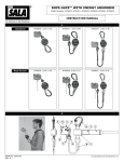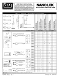
1
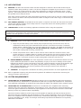
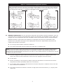
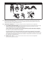
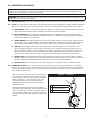
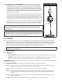
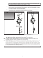
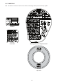
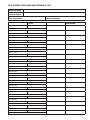
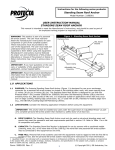
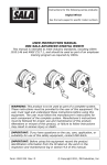
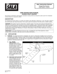
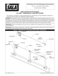
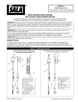
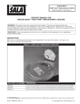
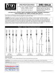
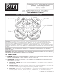
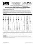
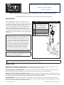
Instructions for the following series products:
Hoist Line Tension Limiter
Model: 3601490
User Instruction Manual for Hoist Line Tension Limiter
This manual should be used as part of an employee training program.
DESCRIPTION
Hoist Line Tension Limiter: This device is to be
connected between a worker and a winch hoist line.
It provides a clutching (slipping) action that activates
if the worker experiences excess loading, thus
reducing the potential for injury. A full body harness
with front and dorsal (back) D-ring or full body
harness with dorsal D-ring and boatswain’s chair must
be used in conjunction with a back-up self retracting
lifeline (SRL) or vertical lifeline and rope grab system.
See Figure 1.
WARNING: This product is part of a work
positioning, suspension, or rescue system. These
instructions must be provided to the user and
rescuer (see section 8.0 Terminology). The user
must read and understand these instructions or
have them explained to them before using this
equipment. The user must read and follow the
manufacturer’s instructions for each component
or part of the complete system. Manufacturer’s
instructions must be followed for proper use
and maintenance of this product. Alterations
or misuse of this product or failure to follow
instructions may result in serious injury or death.
IMPORTANT: If you have questions on the use,
care, or suitability of this equipment for your
application, contact DBI‑SALA.
Figure 1 - Hoist Line Tension Limiter in Use
A
Mandatory:
Backup Personal Fall Arrest
System - Self Retracting
Lifeline (SRL) or Vertical
Lifeline & Rope Grab System
B
Hoist Line
C
Tension Limiter
D
Full Body Harness
E
Boatswain’s Chair (Optional)
B
C
A
D
E
IMPORTANT: Before using this equipment, record the product identification information from the ID label
into the inspection and maintenance log in section 10.0 of this manual.
Definitions
Personal Fall Arrest System (PFAS): A system designed to arrest or stop the fall of a worker prior to
hitting the ground or an obstruction below, thus reducing the potential for injury.
Self Retracting Lifeline (SRL): A device with a spooled line that is used by a worker to provide vertical
mobility while working and designed to lock off quickly if the worker falls, thus arresting the fall.
Vertical Lifeline and Rope Grab System: A system whereby a rope grab, which is connected to the user
will move along a vertically suspended rope and provide vertical mobility and protection, and will lock off and grab
the rope in the event of sudden movement or a fall to arrest the fall of the worker.
Lifting Winch: A winch with spooled wire rope used for lifting equipment. In the past this device has been
used to lift workers. However, many winches do not have a built in clutch designed to slip. Regulations prevent the
use of non-man-rated winches for lifting personnel.
Form: 5903427 Rev B
© Copyright 2012, DB Industries, Inc.
1.0APPLICATIONS
1.1PURPOSE: The Hoist Line Tension Limiter has been designed to reduce the forces that workers may be
exposed to when being raised by a winch. The device is designed to lengthen by as much as 7 m (23 feet)
by the extension of a bright yellow wire rope when subjected to a continuous load higher than 1.78 kN
(400 lb.), thus limiting the force on the worker who may have been caught up in the structure, and giving
the operator time to stop the winch.
ote: Many winches intended for raising and lowering personnel are set to slip or clutch at a load much higher
N
than is safe for the worker. This may be because the winch is designed to lift a work cage, or because the slip
load is set too high.
1.2 FALL ARREST (BACKUP): A separate fall arrest system is required to be used with the Hoist Line Tension
Limiter. This typically consists of a full body harness in conjunction with a self retracting lifeline or vertical
lifeline and rope grab system.
1.3LIMITATIONS: Consider the following application limitations before using this equipment:
Warning: Do not alter or intentionally misuse this device. Consult DBI‑SALA when using this device with
components or subsystems other than those described. Some subsystems and component combinations may
interfere with the operation or safety of the system.
warning: The Tension Limiter is not an SRL and should not be used as a PFAS. The unit must not see any
free fall!
A. CAPACITY: There are two options available for raising workers with the Hoist Line Tension Limiter:
1. Single use personal raising: To be used by only one person at any one time for work, such as,
maintenance and servicing when attached to the hoist line. The worker must have a combined
weight (person, clothing, tools, etc.) of no more than 141 kg (310 lbs.). The label on the housing on
this device is marked “Capacity: 59-141 kg (130-310 lb.) (single user only).” The winch must
have a safe working load of 703 kg (1,550 lb) min.
2. Double use personal rescue: When a winch must be used to raise two workers at a time, each
worker must be on a separate Hoist Line Tension Limiter and they may not be linked to each other.
Note: The capacity of each Hoist Line Tension Limiter remains a single user weighing 59-141 kg
(130-310 lb.). The winch must have a safe working load of 1406 kg (3,100 lb) min.
B. ENVIRONMENTAL HAZARDS: Use of this equipment in areas where environmental hazards exist may
require additional precautions to reduce the possibility of injury to the user or damage to the system.
Hazards may include, but are not limited to: high heat, caustic chemicals, corrosive environments, high
voltage power lines, explosive or toxic gases, moving machinery, antennas, and sharp edges.
Note: Contact DBI-SALA if you have any questions about using this system where physical or
environmental hazards exist.
C.
TRAINING: This equipment is intended to be used by persons trained in its correct application and use.
1.4. Refer to applicable company and governmental regulations for additional requirements concerning the
raising of workers with hoist lines.
2.0 System Requirements
2.1 COMPATIBILITY OF COMPONENTS: DBI/Sala is designed for use with DBI/Sala approved components
and subsystems only. Substitutions or replacements made with non-approved components or subsystems
may jeopardize compatibility of equipment and may effect the safety and reliability of the complete system.
2.2 COMPATIBILITY OF CONNECTORS: Connectors are considered to be compatible with connecting
elements when they have been designed to work together in such a way that their sizes and shapes do not
cause their gate mechanisms to inadvertently open regardless of how they become oriented. Contact DBI/
SALA if you have any questions about compatibility.
Connectors (hooks, carabiners, and D-rings) must be capable of supporting at least 22.2kN (5,000 lbs.).
Connectors must be compatible with the anchorage or other system components. Do not use equipment
that is not compatible. Non-compatible connectors may unintentionally disengage. See Figure 3. Connectors
must be compatible in size, shape, and strength. Self locking snap hooks and carabiners are required by
ANSI Z359.1 and OSHA.
2
Figure 3 - Unintentional Disengagement (Rollout)
If the connecting element to which a snap hook (shown) or carabiner attaches is undersized or irregular in
shape, a situation could occur where the connecting element applies a force to the gate of the snap hook
or carabiner. This force may cause the gate (of either a self-locking or a non-locking snap hook) to open
which will allow the snap hook or carabiner to disengage from the connecting point.
Small ring or
other non-compatibly shaped
element
1.Force is applied to the snap hook.
2. The gate presses against the
connecting ring
3. The gate opens allowing the snap
hook to slip off
2.3making CONNECTIONS: Only use self-locking snap hooks and carabiners with this equipment. Only use
connectors that are suitable to each application. Ensure all connections are compatible in size, shape, and
strength. Do not use equipment that is not compatible. Ensure all connectors are fully closed and locked.
DBI/Sala connectors (snap hooks and carabiners) are designed to be used only as specified in each
product’s user instructions. See Figure 4 for inappropriate connections. Capital Safety snap hooks and
carabiners should not be connected:
A. To a D-ring to which another connector is attached.
B. In a manner that would result in a load on the snap hook or carabiner gate.
NOTE: Large throat opening snap hooks should not be connected to standard size D-rings or similar objects
which will result in a load on the gate if the hook or D-ring twists or rotates. Large throat snap hooks are
designed for use on fixed structural elements such as rebar or cross members that are not shaped in a way that
can capture the gate of the hook.
C. In a false engagement where features that protrude from the snap hook or carabiner catch on the
anchor and, without visual confirmation, seems to be fully engaged to the anchor point.
D. To each other.
E. Directly to webbing or rope Lanyard or tieback (unless the manufacturer’s instructions for both the
Lanyard and connector specifically allows such a connection).
F. To any object which is shaped or dimensioned such that the snap hook or carabiner will not close and
lock, or that roll-out could occur.
g. In a manner that does not allow the connector to align with the fall arrest device (i.e., lanyard) while
under load.
3
Figure 4 - Inappropriate Connections
2.4 Back-Up Fall Protection: A self retracting lifeline or vertical lifeline and rope grab system must
be connected to the worker’s dorsal D-ring and to a suitable anchor point directly above the work area
whenever the Hoist Line Tension Limiter is in use.
2.5 ANCHORAGE STRENGTH: The anchorage strength required is dependent upon the application:
A. Fall Arrest (Backup System): Anchorages selected for fall arrest systems shall have a strength
capable of sustaining static loads applied in the directions permitted by the system of at least:
1. 22.2 kN (5,000 lbs.) for non-certified anchorages, or
2. Two times the maximum arresting force for certified anchorages. When more than one fall arrest
system is attached to an anchorage, the strengths set forth in (1) and (2) above shall be multiplied by
the number of systems attached to the anchorage.
rom OSHA 1926.500 and 1910.66: Anchorages used for attachment of personal fall arrest systems
F
shall be independent of any anchorage being used to support or suspend platforms, and capable of
supporting at least 2,267 kg (5,000 lbs.) per user attached, or be designed, installed, and used as part
of a complete personal fall arrest systems which maintains a safety factor of at least two, and is under
the supervision of a qualified person.
B. Winch hoist Line: The winch hoist line used to raise a worker must meet all applicable
governmental regulations and laws.
4
3.0 OPERATION AND Usage
WARNING: Do not alter or intentionally misuse this device. Consult DBI‑SALA when using this device with
components or subsystems other than those described. Some subsystems and component combinations may
interfere with the operation or safety of the system.
Warning: Do not allow oil or water to enter the Tension Limiter Housing. Exposure of internal components to
oil or water will reduce pull-out capacity.
3.1
BEFORE EACH USE of this device, carefully inspect in accordance with the steps listed in section 5.2 of this manual.
3.2plan your fall arrest and work positioning system before using this equipment. Consider all factors that will
affect your safety during use of this equipment. Consider the following points when planning your system:
A.ANCHORAGE: Select a rigid anchor point that is capable of sustaining the loads specified in section 2.5.
Select anchorage locations that will minimize free fall and swing fall hazards.
B. FALL Clearance: Ensure sufficient clearance exists in your fall path to prevent striking an object
during a fall. The clearance required is dependent upon the subsystem (rope grab, lifeline and lanyard,
self retracting lifeline etc.) properties.
C. SHARP EDGES: Avoid working where your Hoist Line Tension Limiter, or other system components will
be in contact with, or abrade against, unprotected sharp edges. If working with this equipment around
sharp edges is unavoidable, provide protection by using a heavy pad over the exposed sharp edge.
D.RESCUE: The employer must have a rescue plan when using this equipment. The employer must
have the ability to perform a rescue quickly and safely. In the unlikely event that the winch power is
shut down and no auxiliary power is available, the worker can attempt to pull himself to the structure,
disconnect from the hoist line, and climb down while protected by the back-up fall arrest system. A
second worker may be required to pull or assist the suspended worker to grab onto the structure.
E. AFTER A FALL: Any equipment which has been subjected to the forces of arresting a fall or exhibits
damage consistent with the effect of fall arrest forces as described in section 5.0, must be removed from
service immediately and destroyed by the user, the rescuer, or an authorized person.
F. GENERAL USE: Avoid working where your lifeline may cross or tangle with that of another worker.
3.3 Donning and use: Prior to raising a worker, the winch hoist line hook must be lowered to a safe access
location. The worker must don their full body harness and connect the snap hook of their back‑up personal fall
arrest system to the dorsal (back) D-ring on their harness. The Hoist Line Tension Limiter is connected to the
winch hoist line. See Figure 1.
Note: If the winch hoist line hook is not auto locking,
an auto‑locking carabiner must be used to connect
to the cable eye above the hoist line hook for added
safety (see Figure 5). The lower end of the Hoist
Line Tension Limiter may then be connected to
the worker’s front D‑ring or to the D-ring on the
Boatswain’s Chair.
Raising and lowering of personel at high speeds or
with sudden starts and stops must be avoided. Under
these circumstances, the Hoist Line Tension Limiter
may prematurely deploy due to excessive loading or
the user’s personal fall arrest system my prematurely
engage.
5
Figure 5 - Connection
B
A
A
Auto-locking Carabiner
B
Hoist Line Cable Eye
C
Hoist Line Tension Limiter
C
3.4 IN THE EVENT OF OVERLOADING: If while being raised, the worker gets
caught on a structure, the Hoist Line Tension Limiter will begin to deploy
to limit the load on the worker. No alarm will sound, but the bright yellow
cable will pay out (see Figure 6) and continue to deploy until the hoist line
is stopped. The worker on the winch hoist line must always be in visual and/
or audible communication with the winch operator so the suspended worker
can order the winch operator to stop before the Hoist Line Tension Limiter’s
deployment limit is reached.
Figure 6 - Deployment
After the winch is stopped, the winch hoist line and worker must be lowered
to the ground so the Hoist Line Tension Limiter can be reset. The load must
be removed from the device and the reserve (yellow) cable retracted into the
housing. The unit must be inspected to the requirements in section 5.2. Once
completed, the worker can reconnect to the system and be raised again.
If the Hoist Line Tension Limiter is deployed, resulting in the yellow cable being
deployed from the unit in excess of 5 ft. (1.5 m), the unit must be removed
from service and returned to a factory authorized service center for repair.
A
Warning: The winch must be shut down prior to maximum deployment of the
Hoist Line Tension Limiter. After extending 7 m (23 feet) of yellow cable, the
device is fully extended. Further raising of the hoist line may result in serious
injury or death.
WARNING: Do not bounce on the winch hoist line while suspended or
intentionally hold on to the rig structure while being raised. The additional force
may deploy the reserve line on the Hoist Line Tension Limiter unit and require the
worker to be lowered to the ground to reset the unit.
A
Yellow Cable
4.0TRAINING
4.1 It is the responsibility of all users of this equipment to understand these instructions, and to be trained
in the correct use, inspection, and care of this device and the accompanying fall arrest equipment. These
individuals must be aware of the consequences of improper installation, use, and care of this equipment.
This user manual is not a substitute for a comprehensive training program performed by a competent
person. Training must be provided periodically to ensure proficiency of the users.
WARNING: Training must be conducted without exposing the trainee to a fall hazard. Training should be
repeated on a periodic basis.
5.0INSPECTION
5.1FREQUENCY:
• Before Each Use v
isually inspect the Hoist Line Tension Limiter according to steps listed in section 5.2.
• Annually: The Hoist Tension Limiter must be returned to a CSG Authorized Service Center on an annual
basis for inspection. Contact your DBI-SALA distributor to arrange annual factory inspection.
IMPORTANT: Extreme working conditions (harsh environments, prolonged use, etc.) may require increasing the
frequency of inspections.
5.2INSPECTION STEPS: See Figure 7 for components identified in the following steps:
Step 1. Check for worn, loose or damaged components. Ensure that all hardware is present and secure.
Inspect for sharp edges, burrs, cracks, breaks or other damage.
Step 2. Inspect the cable near the Hook Thimble (E) for signs of corrosion or damage.
Step 3. Grasp above the Cable Bumper (C) and pull up on the Protective Tubing (D) and down on the
bumper to separate them slightly to allow inspection of the cable under the tubing for signs of
corrosion.
Step 4. Inspect exposed metal parts on the exterior of the device housing such as the Fasteners (B) for
signs of corrosion.
Step 5. Inspect the Lifeline Hook (F) and Suspension Carabiner (A) for signs of corrosion.
6
Important: Signs of corrosion found during the inspection (e.g., white dust, brown or red
rust) may be an indication that other internal or unexposed parts, such as the cable, may also
be corroded. If corrosion is identified, remove the unit for service.
Step 6. Check to ensure that the device is not deployed. If the reserve (yellow) cable line (Figure 6): is
visible when not under tension, will not retract, or is pulled out by the weight of the user, then the
Hoist Line Tension Limiter must be taken out of service for repair and/or recertification. Do not use
the system if inspection reveals an unsafe condition.
Step 7. If the Hoist Line Tension Limiter cable has deployed in excess of 5 ft (1.5m), the unit must be
removed from service and returned to a factory authorized service center.
Figure 7 - Hoist Line Tension Limiter Inspection Points
A
Suspension Carabiner
B
Fasteners
C
Cable Bumper
D
Protective Tubing
E
Hook Thimble
F
Lifeline Hook
Figure 8 - i-Safe™ RFID Tag
A
B
D
C
E
F
Step 8. Inspect labels. All labels must be present and fully legible. See section 9.0.
Step 9. Inspect each system component or subsystem according to manufacturer’s instructions.
Step 10.Record the inspection date and results in the inspection log in section 10.0.
5.3 If inspection reveals a defective condition, stop using the device and/or remove the unit from service
immediately and contact a factory authorized service center for repair.
5.4 i-Safe™ RFID Tag: The i-Safe™ RFID Tag on the Tension Limiter Cable Bumper (see Figure 8) can be used
with the i-Safe Handheld Reading device and web-base portal to simplify inspection record keeping and
inventory control for your fall protection equipment. If you are a first-time user, contact a Customer Service
representative in the US at 800-328‑6146 or in Canada at 800‑387‑7484 or if you have already registered,
go to: www.capitalsafety.com/isafe. Follow the instructions provided with your i-Safe handheld reader or on
the web portal to transfer your data to your web log.
IMPORTANT: Only DBI-SALA or parties authorized in writing may make repairs to this system.
7
6.0 MAINTENANCE, SERVICING, STORAGE
6.1 Clean the exterior of the Tension Limiter periodically with water and a mild detergent solution using a
sponge or cloth. Avoid introducing water inside the Tension Limiter. Wipe the connector hooks clean with a
dry cloth. Hang the Tension Limiter to dry; do not force dry with heat. If you have any questions regarding
the cleaning or require more information contact DBI‑SALA. An excessive buildup of dirt, paint etc. may
prevent the Tension Limiter from working properly. If you have any questions concerning the condition of
your Hoist Line Tension Limiter, or have any doubt about safe use, contact DBI‑SALA.
6.2 Additional maintenance and servicing procedures must be completed by an authorized service center.
Authorization must be in writing. Do not disassemble this equipment.
6.3 Store the Hoist Line Tension Limiter in a cool, dry, clean environment, out of direct sunlight. Avoid areas
where chemical vapors may be present. Thoroughly inspect the equipment after extended storage.
7.0SPECIFICATIONS
7.1MATERIALS:
Locking Snap Hook: Stainless steel
Housing: Aluminum
Drum: Aluminum
Side Plates: Stainless steel
Fasteners and Locking Pawls: Stainless steel
Lifeline: 3/16-inch diameter stainless steel wire rope, 3,700 lb. (16.5 kN) minimum tensile strength,
7x19, painted yellow.
8.0Terminology
Authorized Person: A person assigned by the employer to perform duties at a location where
the person will be exposed to a fall hazard (otherwise referred to as “user” for the purpose of these
instructions).
Rescuer: Person or persons other than the rescue subject acting to perform an assisted rescue by
operation of a rescue system.
Certified Anchorage: An anchorage for fall arrest, positioning, restraint, or rescue systems that a
qualified person certifies to be capable of supporting the potential fall forces that could be encountered
during a fall or that meet the criteria for a certified anchorage prescribed in this standard.
Qualified Person: A person with a recognized degree or professional certificate and with extensive
knowledge, training, and experience in the fall protection and rescue field who is capable of designing,
analyzing, evaluating and specifying fall protection and rescue systems to the extent required by this
standard.
Competent Person: One who is capable of identifying existing and predictable hazards in the
surroundings or working conditions which are unsanitary, hazardous, or dangerous to employees, and who
has authorization to take prompt corrective measures to eliminate them.
8
9.0labeling
9.1 All Hoist Line Tension Limiters must have the following labels present and fully legible:
ID Label
iSafe Label
Warning, Set Up and Inspection Label
R
Logo Label
9
10
10.0 INSPECTION AND MAINTENANCE LOG
SERIAL NUMBER:
MODEL NUMBER:
DATE PURCHASED:
INSPECTION DATE
DATE OF FIRST USE:
INSPECTION ITEMS
NOTED
CORRECTIVE ACTION
Approved By:
Approved By:
Approved By:
Approved By:
Approved By:
Approved By:
Approved By:
Approved By:
Approved By:
Approved By:
Approved By:
Approved By:
Approved By:
Approved By:
Approved By:
Approved By:
Approved By:
Approved By:
Approved By:
11
MAINTENANCE
PERFORMED
LIMITED LIFETIME WARRANTY
Warranty to End User: D B Industries, Inc., dba CAPITAL SAFETY USA (“CAPITAL SAFETY”) warrants to the
original end user (“End User”) that its products are free from defects in materials and workmanship under
normal use and service. This warranty extends for the lifetime of the product from the date the product is
purchased by the End User, in new and unused condition, from a CAPITAL SAFETY authorized distributor.
CAPITAL SAFETY’S entire liability to End User and End User’s exclusive remedy under this warranty is limited
to the repair or replacement in kind of any defective product within its lifetime (as CAPITAL SAFETY in its sole
discretion determines and deems appropriate). No oral or written information or advice given by CAPITAL
SAFETY, its distributors, directors, officers, agents or employees shall create any different or additional
warranties or in any way increase the scope of this warranty. CAPITAL SAFETY will not accept liability for defects
that are the result of product abuse, misuse, alteration or modification, or for defects that are due to a failure to
install, maintain, or use the product in accordance with the manufacturer’s instructions.
CAPITAL SAFETY’S WARRANTY APPLIES ONLY TO THE END USER. THIS WARRANTY IS THE ONLY WARRANTY
APPLICABLE TO OUR PRODUCTS AND IS IN LIEU OF ALL OTHER WARRANTIES AND LIABILITIES, EXPRESSED
OR IMPLIED. CAPITAL SAFETY EXPRESSLY EXCLUDES AND DISCLAIMS ANY IMPLIED WARRANTIES OF
MERCHANTABILITY OR FITNESS FOR A PARTICULAR PURPOSE, AND SHALL NOT BE LIABLE FOR INCIDENTAL,
PUNITIVE OR CONSEQUENTIAL DAMAGES OF ANY NATURE, INCLUDING WITHOUT LIMITATION, LOST PROFITS,
REVENUES, OR PRODUCTIVITY, OR FOR BODILY INJURY OR DEATH OR LOSS OR DAMAGE TO PROPERTY, UNDER
ANY THEORY OF LIABILITY, INCLUDING WITHOUT LIMITATION, CONTRACT, WARRANTY, STRICT LIABILITY, TORT
(INCLUDING NEGLIGENCE) OR OTHER LEGAL OR EQUITABLE THEORY.
A Capital Safety Company
CSG USA & Latin America
3833 SALA Way
Red Wing, MN 55066-5005
Toll Free: 800.328.6146
Phone: 651.388.8282
Fax: 651.388.5065
[email protected]
CSG Canada
260 Export Boulevard
Mississauga, ON L5S 1Y9
Phone: 905.795.9333
Toll-Free: 800.387.7484
Fax: 888.387.7484
[email protected]
CSG Northern Europe
Unit 7 Christleton Court
Manor Park
Runcorn
Cheshire, WA7 1ST
Phone: + 44 (0)1928 571324
Fax: + 44 (0)1928 571325
[email protected]
CSG EMEA
(Europe, Middle East, Africa)
Le Broc Center
Z.I. 1ère Avenue
5600 M B.P. 15 06511
Carros
Le Broc Cedex
France
Phone: + 33 4 97 10 00 10
Fax: + 33 4 93 08 79 70
[email protected]
CSG Australia & New Zealand
95 Derby Street
Silverwater
Sydney NSW 2128
AUSTRALIA
Phone: +(61) 2 8753 7600
Toll-Free : 1 800 245 002 (AUS)
Toll-Free : 0800 212 505 (NZ)
Fax: +(61) 2 87853 7603
[email protected]
CSG Asia
Singapore:
16S, Enterprise Road
Singapore 627666
Phone: +65 - 65587758
Fax: +65 - 65587058
[email protected]
www.capitalsafety.com
I S O
9001
Certificate No. FM 39709
Shanghai:
Rm 1406, China Venturetech Plaza
819 Nan Jing Xi Rd,
Shanghai 200041, P R China
Phone: +86 21 62539050
Fax: +86 21 62539060