1
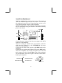
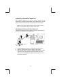
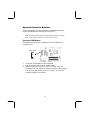
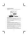
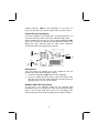
This publication, including all photographs, illustrations and
software, is protected under international copyright laws, with all
rights reserved. Neither this manual, nor any of the material
contained herein, may be reproduced without the express written
consent of the manufacturer.
The information in this document is subject to change without
notice. The manufacturer makes no representations or warranties
with respect to the contents hereof and specifically disclaims any
implied warranties of merchantability or fitness for any particular
purpose. Further, the manufacturer reserves the right to revise this
publication and to make changes from time to time in the content
hereof without obligation of the manufacturer to notify any person
of such revision or changes.
Trademarks
IBM, VGA, and PS/2 are registered trademarks of International
Business Machines.
AMD, Duron and Athlon are registered trademarks of Advanced
Micro Devices Inc.
Intel, Pentium/II/III, and MMX are registered trademarks of Intel
Corporation.
Microsoft, MS-DOS and Windows 95/98/NT/2000 are registered
trademarks of Microsoft Corporation.
PC-cillin and ChipAwayVirus are registered trademarks of Trend
Micro Inc.
AMI is a registered trademark of American Megatrends Inc.
ALi is a registered trademark of Acer Laboratories Inc.
Other names used in this publication may be trademarks and are
acknowledged.
Copyright © 2001
All Rights Reserved
K7AMA(ATA133), V1.5
December 2001
Table of Contents
Trademarks ...................................................................................................I
Chapter 1 ................................................................................................................1
Introduction....................................................................................................... 1
Key Features ................................................................................................2
Package Contents ........................................................................................4
Static Electricity Precautions ....................................................................5
Pre-Installation Inspection.........................................................................5
Chapter 2 ................................................................................................................6
Mainboard Installation ....................................................................................6
Mainboard Components.............................................................................7
I/O Ports ....................................................................................................... 7
Install A CPU..............................................................................................8
Install Memory ..........................................................................................10
Setting Jumper Switches..........................................................................11
Install the Mainboard ...............................................................................13
Install the Extension Brackets ................................................................14
Optional Extension Brackets...................................................................15
Install Other Devices ................................................................................16
Expansion Slots .........................................................................................18
Chapter 3 ..............................................................................................................20
BIOS Setup Utility.........................................................................................20
Introduction................................................................................................20
Running the Setup Utility........................................................................21
Standard CMOS Setup Page ...................................................................22
Advanced Setup Page...............................................................................23
Power Management Setup Page.............................................................25
PCI / Plug and Play Setup Page..............................................................26
Load Optimal Settings .............................................................................27
Load Best Performance Settings............................................................ 27
Features Setup Page.................................................................................. 27
CPU PnP Setup Page................................................................................29
Hardware Monitor Page...........................................................................30
Change Password......................................................................................30
Exit ..............................................................................................................31
Chapter 4 ..............................................................................................................32
Using the Mainboard Software ....................................................................32
About the Software CD -ROM ................................................................32
Auto-installing under Windows 98........................................................33
Manual Installation...................................................................................36
Utility Software Reference......................................................................36
II
Chapter 1
Introduction
This mainboard has a Socket-462 processor socket for an AMD
K7 type CPUs. You can install any one of these processors on the
mainboard.
The mainboard supports Socket-462 processor front-side bus
speeds of 200MHz or 266MHz.
This mainboard uses the ALI M1645 chipset which supports a 4X
AGP slot for highly graphics display, DDR interface and Ultra
DMA 33/66/100/133 function, provides outstanding high system
performance under all types of system operations. The mainboard
has a built-in AC97 Codec, provides an AMR (Audio Modem
Riser) slot to support Audio and Modem application, and has a
built-in 10BaseT/100BaseTX Network Interface (optional) . In
addition, the mainboard has an extended set of ATX I/O Ports
including PS/2 keyboard and mouse ports, two USB ports, a
parallel port, and two serial ports. Two extra USB ports can be
added using the Extended USB Module that connects to the
mainboard.
This mainboard has all the features you need to develop a powerful
multimedia workstation that is network ready. The board is ATX
size and has power connectors for an ATX power supply.
1
Key Features
The key features of this mainboard include:
Socket-462 Processor Support
♦ Supports AMD Athlon/Duron processors
♦ Supports 200/266 MHz Front-Side Bus
Memory Support
♦ Two 168-pin DIMM slots for SDRAM memory modules
♦ Two 184-pin DIMM slots for DDR memory modules
♦ Support for 100/133MHz memory bus
♦ Maximum installed memory is 1GB
Note: You cannot use SDRAM and DDR simultaneously.
Expansion Slots
♦ One AMR slot for a special audio/modem riser card
♦ One AGP4X slot for AGP 2.0-compliant interface
♦ Four 32-bit PCI slots for PCI 2.2-compliant bus interface
Onboard IDE channels
♦ Primary and Secondary PCI IDE channels
♦ Support for PIO (programmable input/output) modes
♦ Support for Multiword DMA modes
♦ Support for Bus Mastering and Ultra DMA 33/66/100/133
modes
Power Supply and Power Management
♦ ATX power supply connector
♦ ACPI and previous PMU support, suspend switch,
keyboard power on/off
♦ Supports Wake on Modem, Wake on LAN and Wake on
Alarm
2
AC’97 Codec
♦ Compliant AC’97 2.1 specification
♦ Supports 18-bit ADC (Analog Digital Converter) and DAC
(Digital Analog Converter) as well as 18-bit stereo fullduplex codec
Onboard I/O Ports
♦ Provides PC99 Color Connectors for easy peripheral device
connections
♦ Floppy disk drive connector with 1Mb/s transfer rate
♦ Two serial ports with 16550-compatible fast UART
♦ One parallel port with ECP and EPP support
♦ Two USB ports and optional two USB ports module
♦ Two PS/2 ports for keyboard and mouse
♦ One infrared port connector for optional module
Hardware Monitoring
♦ Built-in hardware monitoring for CPU & System
temperatures, fan speeds and mainboard voltages
Built-in Ethernet LAN (optional)
♦ Built-in 10BaseT/100BaseTX Ethernet LAN
♦ LAN controller integrates Fast Ethernet MAC and PHY
compliant with IEEE802.3u 100BASE-TX, 10BASE-T and
ANSI X3.263 TP-PMD standards
♦ Compliant with ACPI 1.0 and the Network Device Class
Power Management 1.0
♦ High Performance provided by 100Mbps clock generator
and data recovery circuit for 100Mbps receiver
Onboard Flash ROM
♦ Supports Plug and Play configuration of peripheral devices
and expansion cards
Dimensions
♦ ATX form factor (30.5cm x 22cm)
3
Package Contents
Your mainboard package ships with the following items:
q The mainboard
q This User’s Guide
q 1 UDMA 66/100 IDE cable
q 1 Floppy disk drive cable
q Support software on CD-ROM disk
Optional Accessories
You can purchase the following optional accessories for this
mainboard.
q Extended USB module
q 1 LAN module
4
Static Electricity Precautions
Components on this mainboard can be damaged by static
electricity. Take the following precautions when unpacking the
mainboard and installing it in a system.
1. Keep the mainboard and other components in their original
static-proof packaging until you are ready to install them.
2. During installation, wear a grounded wrist strap if possible. If
you don’t have a wrist strap, discharge static electricity by
touching the bare metal of the system chassis.
3. Handle the mainboard carefully by the edges. Avoid touching
the components unless it is absolutely necessary. During
installation put the mainboard on top of the static-protection
packaging it came in with the component side facing up.
Pre-Installation Inspection
1. Inspect the mainboard for damage to the components and
connectors on the board.
2. If you suspect that the mainboard has been damaged, do not
connect power to the system. Contact your mainboard vendor
and report the damage.
5
Chapter 2
Mainboard Installation
To install this mainboard in a system, follow the procedures in this
chapter:
Identify the mainboard components
Install a CPU
Install one or more system memory modules
Verify that any jumpers or switches are set correctly
Install the mainboard in a system chassis (case)
Connect any extension brackets or cables to the mainboard
connector headers
Install any other devices and make the appropriate connections to
the mainboard connector headers.
Note:
1. Before installing this mainboard, make sure jumper JP5 set to
Normal setting. See this chapter for information on locating
JP5 and the setting options.
2. Never connect power to the system during installation. Doing
so may damage the mainboard.
6
Mainboard Components
Use the diagram below to identify the major components on the
mainboard.
Note: Any jumper on your mainboard that do not appear in
the illustration above is for testing only.
I/O Ports
The illustration below shows a side view of the built-in I/O ports
on the mainboard.
PS/2 Mouse
USB Ports
PS/2 Keyboard
Game/MIDI Port
Parallel Port
Line Out
Serial COM1/3
Serial COM2/4
7
Microphone
Line In
Install A CPU
This mainboard has a Socket-462 CPU socket for AMD K7
processors.
To ensure reliability, ensure that your processor has a
heatsink/cooling fan assembly.
Do not try to install a Socket-370/Socket-7 processor in the Socket462. A Socket-370/Socket-7 processor such as the PPGA Celeron,
FCPGA Pentium-III, Pentium-MMX, or the AMD K5/K6 does not
fit in the Socket-462.
The following list notes the processors that are currently supported
by this mainboard.
Athlon: 700 MHz~1.3 GHz, FSB: 200 MHz, 266 MHz
Duron: 600~950 MHz, FSB: 200 MHz
Installing a Socket-462 Processor
A processor installs into the ZIF (Zero Insertion Force) Socket-462
on the mainboard.
1. Locate the Socket-462 and CPUFAN1. Pull the locking lever
out slightly from the socket and raise it to the upright position.
Socket-462
CPUFAN1
Pin-1 Corner
2. On the processor, identify the Pin-1 corner by its beveled edge.
3. On the Socket-462, identify the Pin-1 corner. The Pin-1 corner
is at the top of the locking lever when it locked.
8
4. Match the Pin-1 corners and insert the processor into the
socket. No force is required and the processor should drop into
place freely.
5. Swing the locking lever down and hook it under the catch on
the side of the socket. This secures the CPU in the socket.
6. All processors should be installed with a combination
heatsink/cooling fan (the original fan is recommended, the
others’ fan is not), connect the cable from the fan to the CPU
fan power connector CPUFAN1.
See the Setting Jumper Switches section for detail information on
CPU System Bus settings.
9
Install Memory
The mainboard has two 168-pin/184-pin DIMM sockets for
SDRAM/DDR SDRAM (Double Data Rate SDRAM) system
memory modules. You must install at least one memory module in
order to use the mainboard, and you can only use one of the both
SDRAM and DDR SDRAM at the same time .
DDR SDRAM provides 800 MBps or 1 GBps data transfer
depending on whether the bus is 100 MHz or 133 MHz. It doubles
the rate to 1.6 GBps and 2.1 GBps by transferring data on both the
rising and falling edges of the clock. DDR SDRAM uses additional
power and ground lines and requires 184-pin 2.5V unbuffered
DIMM module reather than the 168-pin 3.3V unbuffered DIMMs
used by SDRAM.
DDR1
DDR2
DIMM1
DIMM2
For this mainboard, the maximum memory size is 1GB.
The edge connectors on the memory modules have cut outs, which
coincide with spacers in the DIMM sockets so that memory
module can only be installed in the correct orientation.
To install a module, push the retaining latches at either end of the
socket outwards. Position the memory module correctly and insert
it into the DIMM socket. Press the module down into the socket so
that the retaining latches rotate up and secure the module in place
by fitting into notches on the edge of the module.
The table below lists the model chips of DDR that we have
tested.
Model Chip
K4H2808388-TCBO
HY5DU28822T-H
Manufacture
SAMSUNG
HYUNDAI
See the next section for detail information on SDRAM Type and
RAM Voltage settings.
10
Setting Jumper Switches
Jumpers are sets of pins which can be connected together with
jumper caps. The jumper caps change the way the mainboard
operates by changing the electronic circuits on the mainboard. If a
jumper cap connects two pins, we say the pins are SHORT. If a
jumper cap is removed from two pins, the pins are OPEN.
JP6
1
JP3
1
1
JP2
JP5
JP2A
JP1
1
Jumper J5~J14: SDRAM Type Selector
The ten jumpers all consist of eight sets of 2-pin jumpers. Use
these jumpers to select the SDRAM type for the system memory.
Function
DDR DIMM socket
SDRAM DIMM socket
Jumper Setting
Short all Pins 1-2
Open all Pins 1-2
Jumper JP1: RAM Voltage Selector
Use this 2-pin jumper to select the voltage for the installed
SDRAM module.
Function
3.3V for SDRAM
2.5V for DDR
Jumper Setting
Short Pins 1-2
Open Pins 1-2
Jumper JP2: Codec Selector
Use this jumper to select the onboard audio codec or Audio
Modem Riser (AMR) slot.
Function
Primary codec onboard
Primary codec on AMR slot
Jumper Setting
Short Pins 1-2
Open Pins 1-2
11
Jumper JP2A: CPU System Bus Selector
Use this 3-pin jumper to select if the processor runs on 133 MHz or
100 MHz system bus.
Function
133 MHz system bus
100 MHz system bus
JP2A
Short Pins 1-2
Short Pins 2-3
Jumper JP3: Keyboard Power On Selector
If you enable the keyboard power on feature, you can use hot keys
on your keyboard as a power on/off switch for the system.
Note: The system must provide 1A on the +5VSB (+5V
Standby) signal before using the Keyboard Power On
function.
Function
Disable Keyboard Power On
Enable Keyboard Power On
Jumper Setting
Short Pins 1-2
Short Pins 2-3
Jumper JP5: Clear CMOS Memory
Use this jumper to clear the contents of the CMOS memory. You
may need to clear the CMOS memory if the settings in the Setup
Utility are incorrect and prevent your mainboard from operating.
To clear the CMOS memory, disconnect all the power cables from
the mainboard and then move the jumper cap into the CLEAR
setting for a few seconds.
Function
Normal Operation
Clear CMOS Memory
Jumper Setting
Short Pins 1-2
Short Pins 2-3
Jumper JP6: Onboard LAN Selector
Use this 3-pin jumper to enable or disable the onboard network
adapter.
Function
Enable Onboard LAN
Disable Onboard LAN
Jumper Setting
Short Pins 1-2
Short Pins 2-3
12
Install the Mainboard
Install the mainboard in a system chassis (case). The board is an
ATX size mainboard with a twin-tier of I/O ports. You can install
this mainboard in an ATX case. Ensure that your case has an I/O
cover plate that matches the ports on this mainboard.
Install the mainboard in a case. Follow the instructions provided by
the case manufacturer using the hardware and internal mounting
points on the chassis.
AUDIO1
1
SPK1
ATX1
SW1
SYSTEMFAN1
Connect the power connector from the power supply to the ATX1
connector on the mainboard.
If there is a cooling fan installed in the system chassis, connect the
cable from the cooling fan to the SYSTEMFAN1 fan power
connector on the mainboard.
Connect the cable from the PC speaker to the SPK1 header on the
mainboard.
Connect the case switches and indicator LEDs to the SW1 header.
If there are a headphone jack or/and a microphone jack on the front
panel, connect the cables to the AUDIO1 header on the mainboard.
See the illustrations below for the guide to the SW1 and AUDIO1
headers pin assignments.
AUDIO1
1 2
HDD LED P1-3
Power/ACPI LED P2-4
Power Button P6-8
Reset Switch P5-7
SW1
13
MIC 1
MIC-P 3
FPOUT-R 5
NC 7
FPOUT-L 9
2 GND
4 VCC
6 GND
8 Key
10 GND
Install the Extension Brackets
The extension brackets are used to connect features on the
mainboard to external connectors that can be attached to the system
chassis. Follow the steps below to install the extension brackets.
Note: All the ribbon cables used on the extension brackets
have a red stripe on the Pin-1 side of the cable.
LAN Adapter Extension Bracket (Optional)
This bracket supports an RJ45 network connector and connects to
the built in LAN header on the mainboard.
1
LAN Header
LAN Extension
Bracket
1. On the mainboard, locate the LAN header for t his bracket.
2. Plug the cable from the bracket into the LAN header.
3. In the system chassis, remove a blanking plate from one of the
expansion slots and install the extension bracket in the slot.
Use the screw that held the blanking plate in place to secure
the extension bracket.
14
Optional Extension Brackets
For this mainboard, you can also obtain a USB module extension
bracket. Install them by following the steps below.
Note: All the ribbon cables used on the extension brackets
have a red stripe on the Pin-1 side of the cable.
Extended USB Module
This module bracket has two USB ports for more USB devices
(USB port 3-4).
USB2 Header
1
1. Locate the USB2 header on the mainboard.
2. Plug the bracket cable onto the USB2 header.
3. In the system chassis, remove a slot cover from one of the
expansion slots and install the extension bracket in the opening.
Use the screw that held the slot cover in place to secure the
extension bracket to the chassis.
15
Install Other Devices
Install and connect any other devices in the system following the
steps below.
IDE2
1
IDE1
1
FLOPPY1
1
Floppy Disk Drive
The mainboard ships with a floppy disk drive cable that can
support one or two drives. Drives can be 3.5” or 5.25” wide, with
capacities of 360K, 720K, 1.2MB, 1.44MB, or 2.88MB.
Install your drives and connect power from the system power
supply. Use the cable provided to connect the drives to the floppy
disk drive connector FLOPPY1.
IDE Devices
IDE devices include hard disk drives, high-density diskette drives,
and CD-ROM or DVD-ROM drives, among others.
The mainboard ships with an IDE cable that can support one or two
IDE devices. If you connect two devices to a single cable, you
must configure one of the drives as Master and one of the drives as
Slave. The documentation of the IDE device will tell you how to
configure the device as a Master or Slave device. The Master
device connects to the end of the cable.
Install the device(s) and connect power from the system power
supply. Use the cable provided to connect the device(s) to the
Primary IDE channel connector IDE1 on the mainboard.
If you want to install more IDE devices, you can purchase a second
IDE cable and connect one or two devices to the Secondary IDE
16
channel connector IDE2 on the mainboard. If you have two
devices on the cable, one must be Master and one must be Slave.
Internal Sound Connections
If you have installed a CD-ROM drive or DVD-ROM drive, you
can connect the drive audio cable to the onboard sound system.
On the mainboard, locate the two 4-pin connectors CD1 and CD2 .
There are two kinds of connector because different brands of CDROM drive have different kinds of audio cable connectors.
Connect the cable to the appropriate connector.
+
1
+
1
J15
CD1
CD2
IR1
FIR 1
+5V 3
IRTX 5
2 Key
4 GND
6 IRRX
Infrared Port
You can connect an infrared port to the mainboard. You can
purchase this option from third-party vendors.
1. Locate the infrared port IR1 header on the mainboard.
2. If you are adding an infrared port, connect the ribbon cable
from the port to the IR1 header and then secure the port to an
appropriate place in your system chassis.
Onboard LAN LED Connections
If you have a set indicator LEDs for the onboard LAN
communication, you can connect the LED cable to the header J15.
Pins 1-2 are for Link LED. Pins 3-4 are for 10/100 Mbps mode
LED, the onboard LAN run in 100 Mbps mode when the LED lit.
17
Expansion Slots
This mainboard has four 32-bit PCI slots, one AGP slot and one
AMR slot.
PCI3
PCI1
AMR1
AGP1
PCI4
PCI2
Follow the steps below to install a PCI/AGP/AMR expansion card.
1. Locate the AMR, AGP or PCI slots on the mainboard.
2. Remove the slot cover for this slot from the system chassis.
3. Insert the expansion card edge connector into the slot and press
it firmly down into it so that it is fully inserted.
4. Secure the expansion card bracket to the system chassis using
the screw that held the slot cover in place.
AMR Slot
The AMR (Audio Modem Riser) slot is an industry standard slot
that allows for the installation of a special audio/modem riser card.
Different territories have different regulations regarding the
specifications of a modem card. You can purchase an AMR card
that is approved in your area and install it directly into the AMR
slot.
18
Wake On LAN (WOL)
If you have installed a LAN adapter expansion card, connect the
card to the Wake On LAN connector WOL1. This allows
incoming traffic to resume the system from a software power down.
You need to enable this feature in the BIOS setup utility.
WOL1
Header
WOM1
Header
Wake On Modem
If you have installed a fax/modem card, connect the fax/modem to
the Wake On Modem connector WOM1. You can then use the
setup utility to program your computer to resume from a power
saving mode whenever there is an incoming call to the fax/modem.
19
Chapter 3
BIOS Setup Utility
Introduction
The BIOS Setup Utility records settings and information about
your computer such as the date and time, the kind of hardware
installed, and various configuration settings. Your computer uses
this information to initialize all the components when booting up
and functions as the basis for coordination between system
components.
If the Setup Utility configuration is incorrect, it may cause the
system to malfunction. It can even stop your computer from
booting properly. If this happens, you can use the clear CMOS
jumper to clear the CMOS memory used to store the configuration
information.
You can run the setup utility and manually make changes to the
configuration. You might need to do this to configure some of the
hardware that you install on or connect to the mainboard, such as
the CPU, system memory, disk drives, etc.
20
Running the Setup Utility
Each time your computer starts, before the operating system loads,
a message appears on the screen that prompts you to “Hit <DEL>
if you want to run SETUP”. When you see this message, press the
Delete key and the Main menu page of the Setup Utility appears on
your monitor.
AMIBIOS SIMPLE SETUP UTILITY – VERSION 1.21.01
©2000 American Megatrends, Inc. All Rights Reserved
Standard CMOS Setup
Features Setup
Advanced Setup
CPU PnP Setup
Power Management Setup
Hardware Monitor
PCI / Plug and Play Setup
Change Password
Load Optimal Settings
Exit
Load Best Performance Settings
ESC: Quit
↑↓←→ : Select Item
(Shift)F2 : Change Color
F6: Optimal values
F7: Best performance values
F5 : Old Values
F10: Save&Exit
You can use the cursor arrow keys to highlight any of the options
on the main menu page. Press Enter to select the highlighted
option. To leave the setup utility, press the Escape key. To cycle
through the Setup Utility’s optional color schemes hold down the
Shift key and press F2.
Some of the options on the main menu page lead to tables of items
with installed values. In these pages, use the cursor arrow keys to
highlight the items, and then use the PgUp and PgDn keys to cycle
through the alternate values for each of the items. Other options on
the main menu page lead to dialog boxes which require you to
answer Yes or No by hitting the Y or N keys.
If you have already made changes to the setup utility, press F10 to
save those changes and exit the utility. Press F5 to reset the
changes to the original values. Press F6 to install the setup utility
with a set of default values. Press F7 to install the setup utility with
a set of high-performance values.
21
Standard CMOS Setup Page
Use this page to set basic information such as the date, the time,
the IDE devices, and the diskette drives. If you press the F3 key,
the system will automatically detect and configure the hard disks
on the IDE channels.
AMIBIOS SETUP – STANDARD CMOS SETUP
©2000 American Megatrends, Inc. All Rights Reserved
Date (mm/dd/yy) : Tue Mar 27, 2001
Time (hh/mm/ss) : 14:26:53
Type
Pri Master : Auto
Pri Slave
: Auto
Sec Master : Auto
Sec Slave : Auto
LBA Blk
PIO
32Bit
Size Cyln Head WPcom Sec Mode Mode Mode Mode
On
On
On
On
Floppy Drive A : 1.44MB 3 1/2”
Floppy Drive B : Not Installed
Month : Jan – Dec
Day : 01 – 31
Year : 1901 – 2099
ESC : Exit
↑ ↓ : Select Item
PU/PD/+/- : Modify
(Shift)F2 : Color
F3 : Detect All HDD
Date & Time
Pri Master
Pri Slave
Sec Master
Sec Slave
Use these items to set the system date and time
Floppy Drive A
Floppy Drive B
Use these items to set the size and capacity of the
floppy diskette drive(s) installed in the system.
Use these items to configure devices connected to
the Primary and Secondary IDE channels. To
configure an IDE hard disk drive, choose Auto . If the
Auto setting fails to find a hard disk drive, set it to
User, and then fill in the hard disk characteristics
(Size, Cyls, etc.) manually. If you have a CD-ROM
drive, select the setting CDROM. If you have an
ATAPI device with removable media (e.g. a ZIP
drive or an LS-120) select Floptical.
22
Advanced Setup Page
Use this page to set more advanced information about your system.
Take some care with this page. Making changes can affect the
operation of your computer.
AMIBIOS SETUP – ADVANCED SETUP
(C) 2000 American Megatrends, Inc. All Rights Reserved
Trend ChipAway Virus
Quick Boot
st
1 Boot Device
nd
2 Boot Device
rd
3 Boot Device
Try Other Boot Devices
S.M.A.R.T. for Hard Disks
PS/2 Mouse Support
Boot To OS/2 > 64MB
L1 Cache
L2 Cache
DRAM Time/Freq. by SPD
DDR/SDR CAS Select
Dram Performance
AGP Delay Offset
AGP Driving Strength
Trend ChipAway
Virus
Quick Boot
1st Boot Device
2nd Boot Device
3r d Boot Device
Try Other Boot
Device
S.M.A.R.T. for
Hard Disks
PS/2 Mouse
Support
Boot to OS/2 >
64MB
Enabled
Enabled
IDE-0
Floppy
CDROM
Yes
Disabled
Enabled
No
Enabled
Enabled
Enabled
2.5/3
Normal
Auto
Auto
Quit
↑↓←→ : Select Item
Help
PU/PD/+/ - : Modify
Old Values (Shift)F2 : Color
Load Optimal values
ESC
F1
F5
F6
:
:
:
:
F7
: Load Best performance values
This mainboard has built-in virus protection in the
firmware. Use this item to enable or disable the
built-in virus protection.
If you enable this item, the system starts up more
quickly be elimination some of the power on test
routines.
Use these items to determine the device order the
computer uses to look for an operating system to
load at start-up time.
If you enable this item, the system will also search
for other boot devices if it fails to find an operating
system from the first two locations.
Enable this item if any IDE hard disks support the
S.M.A.R.T. (Self-Monitoring, Analysis and Reporting
Technology) feature.
If this item is set to Enabled, the onboard PS/2
Mouse port will work. Setting this to Disable turns off
the port.
Enable this item if you are booting the OS/2
operating system and you have more than 64MB of
system memory installed.
23
L1/L2 Cache
DRAM Time/
Freq. by SPD
DDR/SDR CAS
Select
Dram
Performance
AGP Delay
Offset
AGP Driving
Strength
Leave these items enabled since all the processors
that can be installed on this board have internal
cache memory.
This item allows you to enable or disable the DRAM
timing/Frequency defined by the Serial Presence
Detect electrical.
If the item DRAM Time/Freq. by SPD is disabled,
you can use this item to determine the operation of
the DDR/SDRAM memory CAS (column address
strobe). We recommend that you leave this item at
the default value.
If the item DRAM Time/Freq. by SPD is disabled,
you can use this item to select the performance of
the installed SDRAM. We recommend that you
leave this item at the default value.
This item can be used to offset driving current on
the delay of AGP cards. Some AGP cards need
delaying than normal driving current in order to
operate. We recommend that you set this item to
Auto by default.
This item can be used to signal driving current on
AGP cards to auto or Manual. Some AGP cards
need stronger than normal driving current in order to
operate. We recommend that you set this item to
Auto by default.
24
Power Management Setup Page
This page sets some of the parameters for system power
management operation.
AMIBIOS SETUP – POWER MANAGEMENT SETUP
(C) 2000 American Megatrends, Inc. All Rights Reserved
Power Management
Ring On Power On
Resume On PME#
RTC Alarm Power On
RTC Alarm Date
RTC Alarm Hour
RTC Alarm Minute
RTC Alarm Second
KeyBoard PowerOn
HotKey Select
Power
Management
Ring On Power On
Resume On PME#
RTC Alarm Power
On / Date / Hour /
Minute / Second
KeyBoard Power
On
Disabled
Disabled
Disabled
Disabled
Every Day
12
30
30
Disabled
N/A
Quit
↑↓←→ : Select Item
Help
PU/PD/+/ - : Modify
Old Values (Shift)F2 : Color
Load Optimal values
ESC
F1
F5
F6
:
:
:
:
F7
: Load Best performance values
Use this item to select a power management
scheme. Both APM and ACPI are supported.
The system can be turned off with a software
command. If you enable this item, the system can
automatically resume if there is an incoming call
on the Fax/Modem. You must use an ATX power
supply in order to use this feature.
The system can be turned off with a software
command. If you enable this item, the system can
automatically resume if there is traffic on the
onboard network adapter or PCI LAN/Modem
card. You must use an ATX power supply in order
to use this feature.
The system can be turned off with a software
command. If you enable this item, the system can
automatically resume at a fixed time based on the
system’s RTC (realtime clock). Use the items
below this one to set the date and time of the
wake -up alarm. You must use an ATX power
supply in order to use this feature.
If you enable this item, you can turn the system on
and off by pressing hot keys on the keyboard. You
must enable the Keyboard Power On jumper and
use an ATX power supply in order to use this
feature.
25
HotKey Select
If the item KeyBoard PowerOn is enabled, you can
use this item to select the hot keys to power on
the system.
PCI / Plug and Play Setup Page
This page sets some of the parameters for devices installed on the
PCI bus and devices that use the system plug and play capability.
AMIBIOS SETUP – PCI / PLUG AND PLAY SETUP
(C) 2000 American Megatrends, Inc. All Rights Reserved
Plug and Play Aware O/S
Primary Graphics Adapter
PCI VGA Palette Snoop
Allocate IRQ for PCI VGA
Yes
PCI
Disabled
Yes
ESC
F1
F5
F6
F7
:
:
:
:
:
Quit
↑↓←→ : Select Item
Help
PU/PD/+/ - : Modify
Old Values (Shift)F2 : Color
Load Optimal values
Load Best performance values
Plug and Play
Aware O/S
Enable this item if you are using an O/S that
supports Plug and Play such as Windows 95 or
98.
Primary Graphics
Adapter
This item indicates if the primary graphics adapter
uses the PCI or the AGP bus. The default PCI
setting still lets the onboard display work and
allows the use of a second display card installed in
a PCI slot.
When this item is enabled, multiple VGA devices
operating on different buses can handle data from
the CPU on each set of palette registers on every
video device.
If this item is enabled, an IRQ will be assigned to
the PCI VGA graphics system. You set this value
to No to free up an IRQ.
PCI VGA Palette
Snoop
Allocate IRQ for
PCI VGA
26
Load Optimal Settings
If you select this item and press Enter a dialog box appears. If you
press Y, and then Enter, the Setup Utility loads a set of fail-safe
default values. These default values are not very demanding and
they should allow your system to function with most kinds of
hardware and memory chips.
Load Best Performance Settings
If you select this item and press Enter a dialog box appears. If you
press Y, and then Enter, the Setup Utility loads a set of bestperformance default values. These default values are quite
demanding and your system might not function properly if you are
using slower memory chips or other low-performance components.
Features Setup Page
This page sets some of the parameters for peripheral devices
connected to the system.
AMIBIOS SETUP – PERIPHERAL SETUP
(C) 2000 American Megatrends, Inc. All Rights Reserved
OnBoard FDC
OnBoard Serial Port1
OnBoard Serial Port2
OnBoard Ir Port
Ir Port Mode
Ir Port IRQ
Ir Port DMA
Ir Transceiver Type
Ir Half -Duplex TimeOut
OnBoard Parallel Port
Parallel Port Mode
EPP Version
Parallel Port IRQ
Parallel Port DMA
OnBoard IDE
Ultra DMA Support
OnBoard AC’97 Audio
OnBoard AC’97 Modem
OnBoard USB Function
USB Function for DOS
OnBoard FDC
Enabled
3F8h/COM1
2F8h/COM2
Disabled
N/A
N/A
N/A
N/A
N/A
378h
Normal
N/A
7
N/A
Both
Disabled
Enabled
Auto
Enabled
Disabled
ESC
F1
F5
F6
F7
:
:
:
:
:
Quit
↑↓←→ : Select Item
Help
PU/PD/+/ - : Modify
Old Values (Shift)F2 : Color
Load Optimal values
Load Best performance values
Use this item to enable or disable the onboard
floppy disk drive interface.
27
OnBoard Serial
Port1/2
OnBoard Ir Port,
IR items
Onboard Parallel
Port
Parallel Port Mode
Use these items to enable or disable the onboard
COM1/2 serial port, and to assign a port address.
Use this item to enable or disable the Infrared
port, and to assign a port address. If you select a
specific address, the resources are assigned to
the IR port, and you can use the five items below
to determine the operation of the IR port
Use this item to enable or disable the onboard
LPT1 parallel port, and to assign a port address.
The Auto setting will detect and available address.
Use this item to set the parallel port mode. You
can select SPP (Standard Parallel Port), ECP
(Extended Capabilities Port), EPP (Enhanced
Parallel Port), or ECP + EPP.
EPP Version
Use this item to determine the EPP version, if
you have set the Parallel Port Mode to EPP
Parallel Port IRQ
Use this item to assign either IRQ 5 or 7 to the
parallel port.
Use this item to assign a DMA channel to the
parallel port. The options are 0, 1 and 3.
Use this item to enable or disable either or both of
the onboard Primary and Secondary IDE
channels.
Parallel Port DMA
Onboard IDE
Ultra DMA Support
Onboard AC’97
Audio
Onboard AC’97
Modem
Onboard USB
Function
USB Function for
DOS
Use this item to set Ultra DMA for IDE devices on
the IDE channels. You must enable this or UDMA
devices will not work at their intended speed.
This item enables or disables the onboard AC’97
audio chip.
This item enables or disables the onboard AC’97
modem chip.
Enable this item if you plan to use the USB ports
on this mainboard.
Enable this item if you plan to use the USB ports
on this mainboard in a DOS environment.
28
CPU PnP Setup Page
This page lets you manually configure the mainboard for the CPU.
The system will automatically detect the kind of CPU that you
have installed and make the appropriate adjustments to the items
on this page.
AMIBIOS SETUP – CPU PnP SETUP
©2000 American Megatrends, Inc. All Rights Reserved
CPU BRAND
CPU Type
CPU Speed
CPU Ratio
AMD K7
Athlon
933 MHz
7.0x
ESC : Quit
↑↓←→ : Select Item
F1 : Help
PU/PD/+/- : Modify
F5 : Old Values (Shift)F2 : Color
F6
: Load Optimal values
F7
: Load Best performance values
CPU BRAND/Type/
Ratio
CPU Speed
These items show the kind, core voltage, ratio and
frequency of CPU that has installed in your
system.
Use this item to set the CPU speed that has
installed in your system.
29
Hardware Monitor Page
This page sets some of the parameters for the hardware monitoring
function of this mainboard.
AMIBIOS SETUP – HARDWARE MONITOR
(C) 2000 American Megatrends, Inc. All Rights Reserved
--- Hardware Monitor --System Temperature
CPU Temperature
System Fan
CPU Fan
5V
3.3Vin
12Vin
Vcore
System / CPU
Temperature
FANs & Voltage
Measurements
30°C/86°F
5.000 V
3.300 V
12.000 V
Quit
↑↓←→ : Select Item
Help
PU/PD/+/ - : Modify
Old Values (Shift)F2 : Color
Load Optimal values
ESC
F1
F5
F6
:
:
:
:
F7
: Load Best performance values
These items display CPU and system temperature
measurement.
These items indicate cooling fan speeds in RPM
and the various system voltage measurements.
Change Password
If you highlight this item and press Enter, a dialog box appears
which lets you enter a Supervisor password. You can enter no more
than six letters or numbers. Press Enter after you have typed in the
password. A second dialog box asks you to retype the password for
confirmation. Press Enter after you have retyped it correctly. The
password is then required to access the Setup Utility or for that and
at start-up, depending on the setting of the Password Check item in
Advanced Setup.
30
Change or Remove the Password
Highlight this item, press Enter and type in the current password.
At the next dialog box, type in the new password, or just press
Enter to disable password protection.
Exit
Highlight this item and press Enter to save the changes that you
have made in the Setup Utility configuration and exit the program.
When the Save and Exit dialog box appears, press Y to save and
exit, or press N to exit without saving.
31
Chapter 4
Using the Mainboard Software
About the Software CD-ROM
The support software CD-ROM that is included in the mainboard
package contains all the drivers and utility programs needed to
properly run the bundled products. Below you can find a brief
description of each software program, and the location for your
mainboard version. More information on some programs is
available in a README file, located in the same directory as the
software.
Note: Never try to install software from a folder that is not
specified for use with your mainboard.
Before installing any software, always inspect the folder for files
named README.TXT, INSTALL.TXT, or something similar.
These files may contain important information that is not included
in this manual.
32
Auto-installing under Windows 98
The Auto-install CD-ROM makes it easy for you to install the
drivers and software for your mainboard.
Note: If the Auto-install CD-ROM does not work on your
system, you can still install drivers through the file manager
for your OS (for example, Windows Explorer). Refer to
Utility Software Reference later in this chapter.
The support software CD -ROM disc loads automatically under
Windows 98. When you insert the CD-ROM disc in the CD-ROM
drive, the autorun feature will automatically bring up the install
screen. The screen has three buttons on it, Setup, Browse CD and
Exit.
Note: If the opening screen doesn’t appear, double-click the
file “setup.exe” in the root directory.
1. Setup
Click the Setup button to run the software installation program.
Select from the menu which software you want to install.
33
2.
Browse CD
The Browse CD button is the standard Windows command that
allows you to open Windows Explorer and show the contents of
the support CD.
Before installing the software from Windows Explorer, look for a
file named README.TXT, INSTALL.TXT or something similar.
This file may contain important information to help you install the
software correctly.
Some software is installed in separate folders for different operating
systems, such as DOS, WIN NT, or WIN98/95. Always go to the
correct folder for the kind of OS you are using.
To install the software, execute a file named SETUP.EXE or
INSTALL.EXE by double-clicking the file and then following the
instructions on the screen.
3.
Exit
The Exit button closes the Auto Setup window.
Note: The following screens are examples only. The screens
and driver lists will be different according to the mainboard
you are installing.
Mainboard ID
The mainboard identification is located in the upper left-hand
corner. Click the Next button to run Auto Setup program.
34
Check the box next to the items you want to install. The default
options are recommended. Click the Next button to run the
Installation Wizard. An item installation screen appears:
Follow the instructions on the screen to install the items.
Drivers and software are automatically installed in sequence.
Follow the onscreen instructions, confirm commands and allow the
computer to restart after each installation.
35
Manual Installation
Insert the CD in the CD-ROM drive and locate the PATH.DOC file
in the root directory. This file contains the information needed to
locate the drivers for your mainboard.
Look for the chipset and mainboard model; then browse to the
directory and path to begin installing the drivers. Most drivers have
a setup program (SETUP.EXE) that automatically detects your
operating system before installation. Other drivers have the setup
program located in the operating system subfolder.
If the driver you want to install does not have a setup program,
browse to the operating system subfolder and locate the readme
text file (README.TXT or README.DOC) for information on
installing the driver or software for your operating system.
Utility Software Reference
All the utility software available on the CD-ROM is Windows
compliant. It is provided only for the convenience of customers.
The following software is furnished under license and may only be
used or copied in accordance with the terms of the license.
Note: The software in these folders is subject to change at
anytime without prior notice. Please refer to the support CD
for available software.
AMI Flash Memory Utility
This utility enables you to erase the system BIOS stored on a Flash
Memory chip on the mainboard, and lets you copy an updated
version of the BIOS to the chip. Proceed with caution when using
this program. If you erase the current BIOS and fail to write a new
BIOS, or write a new BIOS that is incorrect, your system will
malfunction. Refer to Chapter 3, Using BIOS for more information.
36
PC-cillin Software
The PC-CILLIN software program provides anti-virus protection
for your system. This program is available for Windows
2000/ME/98SE and Windows NT. Be sure to check the readme.txt
and install the appropriate anti-virus software for your operating
system.
We strongly recommend users to install this free anti-virus
software to help protect your system against viruses.
Note: Update your virus software regularly to protect
MediaRing Talk – Telephony Software
To install the MediaRing Talk voice modem software for the builtin modem, run MRTALK-SETUP72.EXE from the following
directory:
\UTILITY\MEDIARING TALK
Super Voice – Fax/Modem Software
To install the Super Voice voice, fax, data communication
application for use with the built-in fax/modem, run
PICSHELL.EXE from the following directory:
\UTILITY\SUPER VOICE
CD Ghost
The CD Ghost software enables you to create a virtual cabinet of
CD-ROM drives on your system to help you categorize and
organize your CD collection. A user-friendly interface assists you
in quickly creating images of both CDs and DVDs onto your
system. To install the software, run SETUP.EXE from the
following directory:
\UTILITY\CDGHOST\ENG\CDGHOST
37
Recovery Genius
The Recovery Genius software program is an innovative windows
application system that protects your Hard Disk Drive from virus
intrusion, accidental deletions, and system corruption. To install
the Recovery Genius software program run SETUP.EXE from the
following directory:
\UTILITY\RECOVERY GENIUS\ENG\RECOVERYGENIUS
Language Genius
The Language Genius is a software-based product that helps you to
learn new languages. To install the Language Genius software
program run SETUP.EXE from the following directory:
\UTILITY\LANGUAGE GENIUS\ENG\LANGUAGEGENIUS
PageABC
The PageABC application software enables you to create your own
home page. To install the PageABC, run SETUP.EXE from the
following directory:
\UTILITY\PageABC
38