1
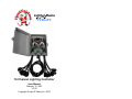
CTB16PC
16 Channel Lighting Controller
User Manual
February 15, 2007
V1.02
Copyright © Light O Rama, Inc. 2007
CTB16PC
Table of Contents
Introduction ............................................................. 4
What’s in the Box .................................................... 6
Getting Started with the CTB16PC.......................... 7
Installing CTB16PC in the Plastic Box..................... 8
Preparing Strain Relief Bracket ........................... 9
General Power Cable Information...................... 11
How to Connect Unit AC Power Cable(s) .......... 12
Single Power Feed (15 amp board max)........ 12
Dual Power Feed (30 amps board max) ........ 13
Installing Power Cables ..................................... 15
Preparing the Rubber Grommets ................... 15
Connecting the Power Cord(s) ....................... 16
Voltage Selection and Operation Jumpers ........ 21
Connecting Controller-to-PC Data Cable........... 22
Assigning a Unit ID ............................................ 23
Testing the CTB16PC........................................ 25
Designing and Playing a Sequence ...................... 26
Troubleshooting .................................................... 27
Status LED ........................................................ 27
AutoConfigure fails to find COM port ................. 27
Hardware Utility Refresh Fails ........................... 28
Updating Controller Firmware ............................... 29
Future Capabilities ................................................ 30
Specifications ........................................................ 31
Introduction
PlanetChristmas and Light-O-Rama are proud to
bring you the CTB16PC. This full function controller
was designed with the Christmas lighting enthusiast
in mind. It is our most economical controller that
sacrifices nothing in terms of the lighting effects.
With some manual assembly labor, you will have a
full function controller ready for use in a weather
resistant plastic box.
The CTB16PC is one of the components in the
Hobbyist line of Light-O-Rama (LOR) products. It
was designed for residential displays. It is a
microprocessor based, intelligent controller that can
perform a number of lighting effects including
dimming, fading, shimmering and twinkling. It can be
daisy-chained with any mix of LOR controllers up to
the maximum of 240 controllers.
The CTB16PC must be used with the LOR Windows
Showtime Software Suite. This software allows you
to configure and test this controller, design your
sequences (sequences are lighting control
command sets), arrange your sequences into shows
and to schedule and play your shows.
To allow your PC to communicate with this
controller, you will need one of Light O Rama’s
RS485 adapters. When you purchase the Generic
Starter Package, you get the LOR Showtime
Software, a 10’ Cat5e network cable and you will be
given a choice of a serial port RS485 adapter or two
types of USB RS485 adapters. Choose the adapter
appropriate for your PC/laptop. The RS485 adapter
4
CTB16PC
will allow you to connect your PC/laptop via the
Cat5e cable to your lighting controller.
This controller is designed to control incandescent or
line voltage LED light strings. It operates on 120/240
VAC, 50/60 Hz. It can handle up to 30 amps when
the factory mounted heat sinks are ordered. The 30
amp configuration can control approximately 9,000
mini-lights.
As with all LOR controllers, this controller is field
firmware upgradeable so you are guaranteed
compatibility with future LOR hardware and software
products.
CTB16PC
What’s in the Box
This depends upon which options you ordered. At a
minimum, you will receive the controller and this
user manual. The latest version of this manual is
also available at www.lightorama.com ► Support ►
CTB16PC User Manual.
The following options are available for this controller:
•
•
•
•
•
•
No heat sinks
Regular heat sinks – these are factory
installed
One 6’ AC power cord and power jumpers
Two 6’ AC power cords
Sixteen 18” AC output receptacles
Outdoor plastic box with internal component
mounting screws and cable strain
relief/grounding bracket
Caution: This product requires that you
have an understanding of electrical
wiring. It requires connections to 120/240
volt AC power. The board has many
exposed line voltage connections that are
dangerous. The board should be mounted
in a safe enclosed box when it is
powered.
5
6
CTB16PC
Getting Started with the CTB16PC
Depending upon the options you selected when
ordering your CTB16PC, you will have to do some of
the following to prepare your CTB16PC for use.
1. Install CTB16PC in the plastic box
2. Prepare strain relief/grounding bracket and
rubber grommets
3. Connect AC unit power cord(s)
4. Connect AC power pigtails (receptacles)
5. Check voltage selection and normal operation
jumpers
6. Connect the network data cable
7. Assign a unit ID
8. Test the CTB16PC
7
CTB16PC
Installing CTB16PC in the Plastic
Box
If you purchased the plastic box for the CTB16PC,
then you should have also purchased the CTB16PC
with regular heat sinks already installed. The screw
holes in the box are designed for the regular heats
sinks.
The heat sinks are held slightly away from the box
by the screws on the back of the heat sinks. Hold
the controller firmly against the back of the box. Use
four of the 3/8”, self tapping screws that came with
the plastic box to attach the controller by its heat
sinks to the plastic box. Tighten the screws just
enough to be snug.
8
CTB16PC
Preparing Strain Relief Bracket
If you purchased the optional plastic box for your
controller, prepare the strain relief/grounding bracket
by removing the bolts and lock washers from the two
grounding studs. Also, remove the four screws and
clamps from the two large cable clamps.
Tighten the cable clamps to the bracket using the
large nuts on the inside of the clamp. Make sure the
screw holes face upward. You can tighten the nuts
snug by hand and then tap them tight with a screw
driver blade and small hammer, or you can tighten
them snug by hand with the clamp about 30º
counter-clockwise and then use a pliers to turn the
clamp clockwise until the screw holes face upward.
The bracket should look like this (the large nuts are
mostly hidden by the vertical support):
9
CTB16PC
Remove the three large rubber grommets from the
bottom of the plastic box. The following picture
shows the positioning of the three 3/8” self-tapping
screws (included) that will hold the bracket to the
plastic box.
3/8" SCREWS USED TO MOUNT STRAIN
RELIEF/GROUNDING BRACKET TO BOX
DO NOT MOUNT THE STRAIN RELIEF/
GROUNDING BRACKET IN THE BOX YET
10
CTB16PC
CTB16PC
General Power Cable Information
How to Connect Unit AC Power Cable(s)
Usual wire coloring:
Hot wires are Black or Brown
Neutral wires are White or Blue
Ground wires are green
On a standard outlet:
Round hole is ground
Short slot is hot
Long slot is neutral
Single Power Feed (15 amp board max)
If you are making your own power connection
cables, be sure the crimp-on quick-connects are
firmly crimped. A loose connection will have
resistance which will result in heat which may result
in fire. Use insulated crimp-on connectors to prevent
shorts.
The next diagram shows how to connect the single
AC power cord to your CTB16PC. If you did not
purchase the power cord from Light-O-Rama, you
will need to construct one 4” white and one 8” black
14 gauge wire quick-connect jumper. Both jumpers
have female quick-connects on each end.
Remember to attach the ground lug to the strain
relief bracket’s grounding stud.
When using zip cord (two wire cord) the wire with the
smooth insulation is used as the hot.
Frayed wires can cause short circuits that can pose
an electrocution hazard, may damage this controller
and pose a fire hazard. Carefully inspect all
connections before applying power. Be sure no stray
strands of wire are sticking out of the crimp-on
connector.
Make sure you push the quick-connect completely
on to the board’s spade lug. Again, a loose
connection will result in resistance which causes
heat and may cause a fire.
11
Note that in this arrangement both fuses are in use,
but the right fuse carries the current for both the left
and right banks of channels. The picture on the next
page is just to illustrate the connections for a single
power feed, do not connect the wires or mount the
bracket yet.
12
CTB16PC
CTB16PC
The following picture is just to illustrate the
connections for the dual power feed, do not connect
the wires or mount the bracket yet.
Dual Power Feed (30 amps board max)
The next diagram shows how to connect the dual
AC power cords to your CTB16PC.
Remember to attach the ground lugs to the strain
relief bracket’s grounding studs.
13
14
CTB16PC
Installing Power Cables
Refer to this picture for instructions that follow:
CTB16PC
have trouble feeding a booted Cat5e cable
connector through the grommet. You may want to
slice the larger grommet along its top side so you
can more easily insert the data cables later.
Connecting the Power Cord(s)
1. The strain relief/grounding bracket should
NOT be installed in the plastic box at this
point. Do all of the following wiring with the
bracket outside the plastic box.
2. Push the quick-connect ends of the single or dual
AC power cord(s) through the large tubular
grommet. The end of the grommet with the
groove that fits into the case must be toward the
quick-connects. Then feed the quick-connect
ends through the center cable clamp as shown
on the previous page. Tighten the cable clamp’s
screws.
Preparing the Rubber Grommets
Three large rubber grommets were removed from
the plastic box earlier. Use a knife to cut the pie
shaped wedges in all the grommets. Cut from the
inside of the grommet towards the center. The
larger, tube shaped grommet will be used for the AC
power and the network connection cables. You may
15
3. Divide the power pigtails into two groups of eight.
Use a Metallic Sharpie or cable labels to mark
the sockets in one group “1” through “8,” mark
the second group “9” through “16.” Use a black
Sharpie to mark the quick-connect on the black
wire so that it corresponds with the marking on
the socket.
4. Push pigtails 1-8 through one of the smaller
rubber grommets. Arrange the cords in the
grommet as three layers, three cords in the top
layer, three cords in the middle layer and two
cords in the bottom layer (the layer near the
curved end of the grommet.) Then push the
quick-connect ends through the large left cable
16
CTB16PC
clamp. About 8½” of cable should extend through
the cable clamp. Put the top half of the clamp
back on and tighten the cable clamp’s screws.
See page 15.
CTB16PC
8. Separate the black, white and green striped
wires and route them as shown in the following
picture:
5. Repeat the above process for the right pigtails
(channels 9-16.)
6. Place the strain relief/grounding bracket into the
plastic box sliding the rubber grommets into
place. Use three 3/8” screws to secure it to the
box as shown on page 10. It should look like this:
9. Slide all green striped ground wires over the
grounding stud nearest the 8 channel group of
wires. Make sure you have all grounds on the
stud, a missed wire could cause a short later. Put
a lock washer and a bolt on the grounding studs.
7. Connect the AC power cord(s) as shown in the
section How to Connect Unit AC Cord(s).
17
10. When pushing on quick-connects, make sure the
blade on the circuit board goes into the quick-
18
CTB16PC
CTB16PC
connect female end. Sometimes the blade will go
between the plastic and the female metal end –
this will not provide a good connection and may
be dangerous. You should not be able to easily
pull off a properly seated quick-connect.
11. Push all white wires on the neutral terminals
grouped together at the center bottom of the
board. Keep channels 1-8 on the left-most set of
neutral terminals and channels 9-16 on the rightmost set. This last step is important for a dual AC
power feed, especially if you are using ground
fault interrupters.
12. Using the previously labeled black wire quickconnects, push them on to the appropriate
terminals along the left and right sides of the
board. Your controller should look as shown on
the next page.
13. This completes the assembly of your controller.
(Note that this picture shows the fuse covers –
these were a late addition designed to protect the
wires passing over the fuses.) You are ready to
configure it for testing.
19
20
CTB16PC
Voltage Selection and Operation Jumpers
For 120 VAC operation, both jumpers should be
installed on the header that is to the lower right of
the transformer. See following picture:
CTB16PC
Connecting Controller-to-PC Data Cable
If you have not installed your RS485 adapter, do it
now. If you have an SC485 (PC serial port adapter,
shown on the left below), you need only plug it into
an available PC 9-pin serial port. The cable from a
serial adapter to the first controller is limited to 100’
or less.
For 240 VAC operation, only one jumper on the
center two pins of this header must be installed.
There must be a jumper on header J0. This is the
larger, 18 pin header in the upper right of the board.
The jumper must be installed on the second row of
pins from the top. This is the normal operation
jumper, if not present the board will reset when
powered and will not be usable until the jumper is
installed and the power cycled. See following
picture:
21
If you have one of the USB adapters (shown center
and right above), follow the installation instructions
that came with the adapter.
If you are using telephone cable to connect your
controller to the RS485 adapter, plug one end of the
phone cable into the adapter and the other end of
the cable into the PHONE CABLE IN jack as
indicated in the picture below.
22
CTB16PC
CTB16PC
If you are using Cat5e LAN cable to connect your
controller to the RS485 adapter, plug one end of the
data cable into the adapter and the other end into
either of the CAT5E CABLE IN or OUT jacks shown
in the previous picture.
Assigning a Unit ID
If you have not installed the Light O Rama Windows
Showtime Software, do it now.
The board will need to be powered at this point –
BE VERY CAREFUL – there are dangerous
voltages present on the exposed circuit board.
Take appropriate precautions with children and
pets.
Plug the CTB16PC power cord(s) into AC power.
The LED near the RJ45 jacks will blink about
twice/second. This means that the board has booted
and is waiting for the PC to talk to it.
Click the Auto Configure button in the Setup Comm
Port section. The Hardware Utility will search for the
COM port that your RS485 adapter is plugged into
and select it.
Start the Hardware Utility – click start ► All
Programs ► LightORama ► Light-O-Rama
Control Panel. There will be a light bulb with a blue
halo on the right side of the task bar at the bottom of
the screen. Right-click the light bulb and select
Hardware Utility from the menu. Make sure the LOR
Control tab is selected. You will see the window
shown on the next page.
When assigning a unit ID, only one controller may
be plugged into the RS485 adapter on the PC. Be
sure you do not have more than one controller
connected.
Steps to set/change unit ID:
1. In the Change Existing ID section, use the Old
Unit ID drop-down menu to select Any Unit, then
click OK in the warning box for changing all unit
IDs, there should only be one unit attached.
2. Use the New Unit ID drop down menu to select
“01” (If you have more than one controller, assign
successive unit IDs to them.)
23
24
CTB16PC
3. Click the Change Unit ID button to set your
CTB16PC unit ID. You will see a Unit ID
Changed box – click OK.
Your CTB16PC is ready for testing.
Testing the CTB16PC
In the Max Units section of the Hardware Utility
window, click the Change button. Move the slider in
the Change Maximum Units box so that the Max
Units is set to 10. This will limit the search for
controllers to the first 10 unit IDs, otherwise 240
controllers would be searched for – taking a long
time. Click the Save button.
In the Select Unit to Configure..Download..Test
section of the Hardware Utility screen, click the
Refresh button to locate your attached CTB16PC
controller. Your controller will appear in the drop
down menu to the right of the Refresh Button.
The Test Unit’s Operation section of the screen
should be active. Plug some lights into your
controller and use the sliders and buttons in this
section to test your controller.
25
CTB16PC
Designing and Playing a Sequence
Lighting commands for your shows are called
Sequences and are designed and implemented
using the Sequence Editor Windows software.
Stop the Hardware Utility. You will not be able to
command your controller from the Sequence Editor if
the Hardware Utility is running. Only one program
may use the RS485 adapter at a time to talk to
lighting controllers.
There are Quick Start Guides for creating animation
(non-musical) and musical sequences, Flash
Tutorials and much more at:
www.lightorama.com ► Support
The following Wiki is also an excellent source of
information on all things Light-O-Rama:
www.lorwiki.com
There is also a very active and helpful Light-O-Rama
user community on Planet Christmas:
www.planetchristmas.com
26
CTB16PC
CTB16PC
Troubleshooting
Unit ID assignment steps with each serial port in
succession.
Status LED
Hardware Utility Refresh Fails
LED blinking approximately twice/second: Controller
has booted correctly and is waiting for commands.
The controller is not connected to a Light O Rama
network or the network is not active.
Use the procedure in the section Assigning a Unit ID
to assign a unit ID to the controller. If this has been
done and Refresh still does not work, try manually
typing the controller number into the box to the right
of the Refresh button. Use the options in the Test
Unit’s Operation section of the Hardware Utility
window to see if the controller can be controlled.
LED is on solid: Controller is connected to an active
network (is receiving the heartbeat and commands
from a PC or a DC-MP3 Show Director)
LED is blinking twice then pause, twice …: The
normal operation jumper is not on J0, the controller
is resetting. See the section Voltage Selection and
Operation Jumpers for placement of the jumper.
AutoConfigure fails to find COM port
If the COM port is not detected, you can manually
select it from the drop down list.
If you are not sure which COM port is the RS485
adapter and you have a USB adapter, click start ►
My Computer ► View System Information ►
Hardware tab ► Device Manager button. Click the
“+” in front of “Ports (COM & LPT)” – you will see
“USB Serial Port (COMn)” – this is the RS485
adapter. Use the Manual Select drop-down box to
select that COM port.
If you are not sure which COM port is the RS485
adapter and you have a serial port RS485 adapter,
you will have to consult your PC’s documentation, it
is normally COM1, COM2 or COM3. You can try the
27
28
CTB16PC
Updating Controller Firmware
Periodically, Light-O-Rama will distribute new
firmware for your CTB16PC. If you believe you need
updated firmware, use the Hardware Utility do
determine your current firmware version. Use the
Refresh button to find your controller and check its
firmware version. The drop-down menu to the right
of the Refresh button will be filled in with the
attached controllers. The right part of the controller
name in this drop-down is the current firmware
version.
If the controller type or firmware version is not
present, get the latest Hardware Utility from
www.lightorama.com ► Support ► (bottom of page)
Download Hardware Utility. Run program
downloaded to install the Hardware Utility and
devices text file. Retry the Refresh operation.
The latest firmware can be found by going to
www.lightorama.com ► Support and scrolling down
to the Using the Hardware – Documentation and
Firmware section. Find your controller and roll the
mouse over the Firmware button – look at the bar in
the lower left of the browser window. It will show the
name of the firmware file. The file name contains the
version at the end. If the version number is greater
than what you saw in the Hardware Utility, new
firmware is available. Click the Firmware button to
download the firmware to your PC – remember
where you put it.
29
CTB16PC
To load new firmware use a data cable (not wireless)
to connect the controller(s) to the PC. Start the
Hardware Utility and click the Refresh button to find
your controller(s). Select the one you want to update
from the drop-down menu to the right of the Refresh
button. Click the Firmware button at the bottom of
the window.
In the Firmware section of the window, under Step
1 – Select Unit, select the unit listed above. Under
Step 2 – Select Firmware File, use the Open
button to browse to the firmware file you
downloaded. Under Step 3 – Press Download
Button click the Download button. Do not interrupt
this process. Your controller will reboot after the
download completes.
You can click the Refresh button to see that the new
firmware was loaded into your controller. Repeat this
process for additional controllers.
Future Capabilities
The eighteen pin header on the board provides for
digital inputs, digital outputs and servo outputs.
These will be activated at a later date.
The digital inputs are designed to work with the
interactive show feature of the LOR II Showtime
Windows Software.
30
CTB16PC
Specifications
Configuration
Individual Channel
Capacity
Individual Bank
Capacity
Board Capacity
Single Power Feed
Board Capacity
Dual Power Feed
Supply Voltage
Fuses
Isolation
Power Connections
No Heat Sinks
Regular Heat Sinks
Plastic enclosure
Two banks of 8 channels
1 amp – No Heat Sinks
8 amps – Regular Heat Sinks
8 amps – No Heat Sinks
15 amps – Regular Heat Sinks
15 amps – No Heat Sinks
15 amps – Regular Heat Sinks
16 amps – No Heat Sinks
30 amps – Regular Heat Sinks
120/240 VAC, 50/60 Hz
15 amp fast acting
Optos isolate line voltage from control
logic
Quick connects (spade lugs)
6 ¾”w x 5 ¼”h x 1 ½”d
7 ¼”w x 6 ¾”h x 2 ¼”d
9 ½”w x 11 ½”h x 3 ½”d
Light-O-Rama, Inc.
Tel: (518) 539-9000
Fax: (518) 538-0067
[email protected]
31