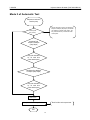
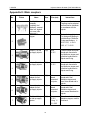
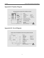
1
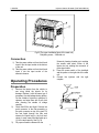
LAUNCH Injector cleaner & tester (CNC-601A/801A) Table of Contents Introduction······························································· 2 Specifications···························································· 2 Structure ·································································· 2 Overview ······························································ 2 Control panel························································· 4 Installation & Connection ········································· 4 Installation ···························································· 4 Connection ··························································· 5 Operating Procedures ················································· 5 Sequences···························································· 6 Tidy-up································································· 6 Operation ································································· 6 Ultrasonic Cleaning················································· 6 Reverse Flush ······················································· 7 Uniformity Test······················································· 7 Sprayability Test····················································· 9 Leakage Test························································· 9 Injecting Flow Test ·················································· 9 Auto. Test ··························································· 10 On-vehicle Cleaning·············································· 13 Maintenance ··························································· 14 1.Transporting and Storing ····································· 14 2. Transportation & Storage of Naked Unit ················· 14 3. Installation Environment ····································· 15 4. List of Easy-damaged Parts ································ 15 5. Test Liquid and Cleanser Selecting or Replacing······ 15 6. O-ring Replacing··············································· 15 7. Filter Replacing ················································ 15 8. Precautions ····················································· 15 Troubleshooting······················································· 16 Warranty ································································ 17 Disclaimer··························································· 17 Order Information ················································· 17 Customer Service················································· 17 Appendix I: Pressure Gauge of Injection System ········· 18 Appendix II: Main couplers ····································· 20 Appendix III: Pipeline Diagram ································ 23 Appendix IIII: Circuit Diagram·································· 23 1 LAUNCH Injector cleaner & tester (CNC-601A/801A) Introduction Specifications Functions: z Ultrasonic cleaning: To clean several injectors at the same time by an ultrasonic cleaner, and remove the carbon deposits on the injector completely. z Reverse flush: To remove the impurities adhered to the injector or screen thoroughly. z On-vehicle Cleaning: The unit is equipped with various adaptors and couplers that may help clean the injectors on vehicle. z Uniformity test: To test the uniformity of injecting amount of each injector. z Sprayability test: To observe the Sprayability status of each injector with the help of backlight. z Leakage test: To test the sealing and dribbling conditions of injectors under high pressure. z Injecting flow test: To check the injecting amount of the injector in 15 seconds of constant injection. z Auto. test: To test injectors by simulating different working conditions. Operating condition: z Temperature: -10~+40℃; z Relative humidity: <85%; z Intensity of outer magnetic field: <400A/m; z No naked flame within 2m. Specifications: z Power supply: □AC220V±10%/50Hz~60Hz □AC110V±10%/ 50Hz~60 Hz z z z z z z z z z z z Input power: 270W; Ultrasonic cleaner power: 100W; Pressure range: 0~0.65Mpa; Pressure step: 0.004Mpa; Simulated RPM range: 10~9990rpm; step: 10rpm; Count range: 1~9999 times; Time range: 1~9999s; Pulse width: 0.5~25ms; step 0.1 ms; Fuel tank capacity: 2500ml; Dimensions: 550mm × 530mm × 1400 mm; Weight: About 80kg. Features: z z z Adopting the powerful ultrasonic cleaning technology, CNC-601A/801A can clean injectors entirely. Microcomputer controlled fuel pressure is stable and adjustable, and conforms to all EGI vehicles, achieves the automatization of cleaning and testing of injectors. With the technology of microcomputer control and digital display, CNC-601A/801A makes real the automatization in cleaning and testing injectors, and conducts the real-time monitoring of dynamic values. Structure Overview CNC-601A/801A injector cleaner& tester is installed in a cabinet with four casters at the bottom for easy operating and moving, as shown in Fig.01. The cover is designed as a slide curtain, which can be pulled up before operating. Under the curtain is the control panel and workbench. There are two layers in the cabinet part, upper layer is for an ultrasonic cleaner working; and the lower layer is drawer for placing tools. There are four pieces of casters under the base seat. 2 LAUNCH Injector cleaner & tester (CNC-601A/801A) Fig.01 14. Socket for pulse signal cable; 15. Gasoline filter; 16. Return hose; 17. Fuel tank; 18. Draining connector; 19. Ultrasonic cleaner; 20. Quick connector; 21. Quick connector for inlet tank; 22. Fuel level viewer; 23. Return fuel viewer; 24. Timing light socket; 25. Backlight switch; 26. Power switch. 1. Curtain; 2. Measuring cup; 3. Control panel; 4. Power switch of the ultrasonic cleaner; 5, 19. Ultrasonic cleaner; 6. Tool kit; 7. Power socket; 8. Fuse; 9. Slider lock; 10. Fuel distributor; 11. Snap-on fuel pipe; 12. T-type block; 13. Overflow valve; Note: The illustrations in this manual may be slightly different from the actual product! 3 LAUNCH Injector cleaner & tester (CNC-601A/801A) Control panel The control panel is as shown in Fig.02 (The control panel of CNC-601A is the same as that of CNC-801A.) Fig.02 The control panel is classified into five areas from left to right as shown in the following table: Area Description z Select a desired function by pressing[▲]/[▼]keys. The corresponding Item selection indicator will come on. Parameter z Select a desired parameter by pressing[▲] [▼] / keys. The corresponding selection indicator will come on. z After selecting function and parameter, user can set the parameter value by pressing[◄]/[►]keys. ([►]key for increasing, and[◄]key for Parameter decreasing.) display z The set value will be displayed on the lower LCD, and the live fuel pressure on the upper LCD. System control z To control the draining, stop and run of CNC-601A/801A. Fuel level z To display the amount of liquid in the fuel tank. display Installation & Connection Installation 1) Loosen the strip that tightens the outlet hose. 2) Take the pulse signal cables from the box and insert it into the socket on the top right side of the machine and tighten it. 3) Take the pulse signal cables from the box and insert it into the socket on the right upper of the ultrasonic cleaner and tighten it. 4) Take the two adjusting screws out from the box and install them to the press plates on the top of the glass tube. 5) Take the two knurled nuts from the box and install them on the adjusting screws. 6) Take the fuel distributor from the box and install it on the knurled nuts and tighten them with the pressing screws. 4 LAUNCH Injector cleaner & tester (CNC-601A/801A) Fig.03 (The upper installation figure of the main unit) 1-Adjusting screw;2-Knurled nut Connection 1) Take the power cables out from the kit and insert it into the input socket at the bottom of the unit. 2) Take the power cables out from the kit and insert it into the input socket of the ultrasonic cleaner. 4) 5) Operating Procedures Ultrasonic cleaning chamber up to soaking the needle valve about 20mm of the injector but not soaking the connector of pulse signal cable. Press the power switch of the backlight and the power on the right side of the main unit. Connect the injectors with the right couplers. Preparation 1) 2) 3) Remove the injector from the vehicle to see o-ring inside the injector for its damage. Replace it with the same type if necessary to avoid leakage during testing. Put the outside of injectors in gasoline or cleanser, and wipe them with a soft cloth after cleaning the outside oil sludge carefully. Check and fill the test liquid. Connect the quick connector of the filler assembly to the quick connector on top of the tank. Fill the test liquid through the filler and observe the liquid level in the fuel level viewer. In most cases, filled the liquid up to 1/2 of the tank capacity. See Fig. 04. Fill proper ultrasonic cleanser into the Fig 04 5 LAUNCH Injector cleaner & tester (CNC-601A/801A) Operation Note: Test liquid and cleanser are provided together with the unit. The test liquid is used for uniformity/sprayability test, leakage test, injecting flow test and auto. test. The mixture of fuel and cleanser is used in on-vehicle cleaning. The ultrasonic cleaning uses special ultrasonic cleanser (or test liquid and cleanser that comes with by the unit). Ultrasonic Cleaning CNC-601A/801A takes advantage of the penetrability and cavitation impact wave caused by ultrasonic wave traveling through the medium, which may provide powerful cleaning of impurities to object with complex shapes, cavities and pores, to completely remove the stubborn carbon deposits from the injectors. Procedures: 1) Add proper specified ultrasonic cleanser into ultrasonic cleaner. Please refer to use description of ultrasonic cleanser for its detailed using methods and dosage. Ultrasonic cleanser in ultrasonic cleaner should be up to soaking the needle valve about 20mm. 2) Place the ultrasonic cleaner bracket on the ultrasonic cleaner. Place the outer-cleaned injectors on the launder supporter of CNC-601A/801A. 3) Plug the injector pulse signal wire to the socket under the control panel (top right corner of the ultrasonic cleaner), and the injector drive signal wires to injectors respectively. 4) Turn on the power switch of the ultrasonic cleaner. 5) Select [Ultrasonic cleaning] in the function column by[▲]/[▼] keys. Select [Timing] in the parameter column, and set the timing value (the default time is about 10 minutes) in the value column. Press [Run] button to start cleaning. 6) When the time is up, CNC-601A/801A will stop automatically with the buzzer ringing. 7) Turn off the ultrasonic cleaner. Remove the injector pulse signal wires from injector and tie them orderly. Take the injectors out of the launder and wipe them with a dry soft cloth. Prepare for next operation. Sequences A complete cleaning and testing sequence shown below should be followed: z Ultrasonic cleaning; z Reverse flush (only for fuel top-supply injector); z Uniformity test; z Sprayability test; z Leakage test; z Injecting flow test; z Auto. test Select and set up the corresponding parameter according to the various testing purpose. For detailed operations, please refer to “Operation” part. Tidy-up Remember to do the following work after cleaning and testing: z Press [Drain] button to drain the test liquid into fuel tank. z Switch off the power and unplug the power plug. z Dump the ultrasonic cleanser to its original bottle, and then wipe the ultrasonic cleaner with a soft cloth. z Clean the CNC-601A/801A control panel with a soft cloth. z Drain the test liquid from the tank into a container to avoid volatilization. Store the liquid in a safe place if it can be used again, or dispose of it in accordance with relevant regulations if it is too dirty. 6 LAUNCH Injector cleaner & tester (CNC-601A/801A) Note: In reverse flush, the pulse width of the injector is automatically set as a fixed value in program. The user doesn’t have to do manual setting. In reverse flush, the unit will continuously drain the test liquid during operation to avoid spillover. Note: Before the ultrasonic cleanser is added into ultrasonic cleaner, do not turn on the ultrasonic cleaner. Otherwise, damage may be incurred. Reverse Flush Reverse flush is a way to clean the injectors with the test liquid flowing from the outlet to the inlet of the injector. Reverse flush may remove the dirt inside the injector or adhered on the screen. (For top fuel supply injector) Procedures: 1) Choose the fuel distributor stopper from the coupler box and mount a proper O-ring on it. Remember to apply a little lubricating oil on the O-ring (avoid O-ring damage and leakage). Mount the fuel distributor stopper to the distributor. 2) Mount the crescent plate and tighten it with a bolt. 3) Choose a reverse flush coupler and proper O-ring, and mount them under the fuel distributor. 4) Install the injectors in reverse direction (outlet upward, and inlet downward). 5) If needed, choose a proper lower coupler (such as hexagonal wide sleeve, hexagonal narrow sleeve, etc.) according to the shape of the injector and put it under the injector. 6) Install the fuel distributor and the injector on the fuel distributor supporter with a proper adjustable screw and knurled nuts, and tighten two riffle screws (black). See Fig. 05. 7) Connect the injector pulse signal wire. 8) Select [Reverse flush] in the function column. Set fuel pressure (usu. 2~4kg/cm2) and the cleaning time (default time: 10s) on the control panel, and press [Run] button to start cleaning. 9) When the cleaning is over, CNC-601A/801A will automatically stop with the buzzer ringing. Fig. 05 1-Plate bolt; 2-Crescent plate; 3-Fuel distributor stopper; 4-Flush-back adaptor; 5-injector; 6-Knurled nut; 7-Adjustable screw; 8-Riffle screw; 9,10,11-O-ring; 12-Fuel distributor; 13-O-ring; 14-Couplers. Uniformity Test Uniformity test is to test the injectors on the same vehicle under the same working condition to see if the injecting difference of each injector meets the requirement or within specifications. This test can reflect the comprehensive influences on the injector caused by electrical characteristics, bore variation, clogging, etc. Installing and testing procedures for fuel top-supply injectors 1) Choose the fuel distributor stopper from the coupler box and mount a proper O-ring on it. Remember to apply a little lubricating oil on the O-ring (avoid O-ring damage and leakage). Mount the fuel distributor stopper to the distributor. 2) Mount the crescent plate and tighten it with a bolt. (Same as the reverse flush procedures.) 3) Choose a proper adaptor according to the 7 LAUNCH Injector cleaner & tester (CNC-601A/801A) injector type and mount it to the corresponding coupler under the fuel distributor. 4) Install the injectors in forward direction (Apply a little lubricating oil on the O-ring.) 5) Install the fuel distributor and the injector on the fuel distributor supporter with a proper adjustable screw and knurled nuts, and tighten two riffle screws (black). 6) If needed, choose a proper lower coupler (such as hexagonal wide sleeve, hexagonal narrow sleeve, etc.) according to the shape of the injector and put it under the injector. See Fig. 06. 7) Connect the injector pulse signal wire. 8) Before doing uniformity test, press [Drain] button to drain the test liquid from the measuring cup if there is any. 9) Choose [uniformity test] on the control panel. Set corresponding parameters such as pressure, RPM, PW (consult the appendix for pressure set, consult vehicle manuals for other parameters depended on customer need), and press [Run] button. 10) When the test is over, CNC-601A/801A will auto stop with the buzzer ringing. 4) Mount the fuel distributor and injectors onto the fuel distributor supporter, and tighten them with two riffle screws (black). 5) Choose a proper lower coupler (such as hexagonal wide sleeve, hexagonal narrow sleeve, etc.) according to the shape of the injector and put it under the injector. See Fig. 07. 6) Connect the injector pulse signal wire. 7) Before doing uniformity test, press [Drain] button to drain the test liquid from the measuring cup if there is any. 8) Choose [Uniformity test] on the control panel, set corresponding parameters such as pressure, PRM, PW (consult the appendix for pressure set, consult vehicle manuals for other parameters depended on customer need), and press [Run] button. 9) When the testing is over, CNC-601A/801A will auto stop with the buzzer ringing. Fig. 07 1-Cross plate; 2-Fuel side-supply injector; 3Coupler for fuel side-supply injector; 4,5-O-ring; 6-Fuel distributor Note: ♦ Keep the liquid level to at least 30 ml while testing. Foam will be produced in the liquid during injection. In order to prevent spillover, set the related parameter with reference to the following formula : Fig. 06 1-Adapter for fuel top-supply injector Installing and testing procedures for fuel side-supply injectors 1) Choose proper couplers for fuel side-supply injectors and proper O-rings, and mount them together. (Remember to apply a little lubricating oil.) 2) Mount the injectors on the couplers and install them onto the fuel distributor. 3) Mount the cross plate and tighten it with bolts. Pulse width(ms)×time(s)×speed(rpm) / 120≤18000 This is for checking the uniformity of each cylinder. 8 LAUNCH ♦ ♦ ♦ Injector cleaner & tester (CNC-601A/801A) Injecting difference of all injectors on one vehicle should be within ±2%. CNC-601A/801A may auto save the values of fuel pressure, rpm and pulse-width. Remember to set the values as needed each time, otherwise, CNC-601A/801A will perform the test on previous-set values. During operation, the user can select parameter, such as RPM or PW, and then press [ ◄ ] or [ ► ] key for simulation of changing working condition. ♦ Sprayability Test test liquid during operation to avoid spillover. In the sprayability test, a special electrical parameter--the minimum injection pulse width of injector--can be tested, to compare the injectors on the same engine. That is to set cylinder No., start the test from minimum injection pulse width, and then gradually increases the pulse width till the injector starts injection (observed with the help of backlight). The value set at this moment is the minimum injection pulse width, so the difference of minimum injection pulse width among these injectors could be observed. Leakage Test Sprayability test is to observe the sprayability status and injecting angles of injectors. Leakage test is to inspect the sealing conditions of the injector needle valve under high pressure, to test if the injector is dribbling. Procedures: 1) Before doing this test, press [Drain] button to drain the test liquid from the measuring cup if there is any. 2) Turn on the backlight switch. 3) Choose [Sprayability test] on the control panel. Set corresponding parameters such as pressure, RPM, PW, timing or injecting times and injecting cylinder number. Press [Run] button. 4) When CNC-801A is running, it can set the injecting order for each injector to observe their sprayability status one by one. 5) When the test is over, CNC-601A/801A will auto stop with the buzzer ringing. Procedures: 1) Before doing this test, press [Drain] button to drain the test liquid from the measuring cup if there is any. 2) Choose [Leakage test] on the control panel, set the fuel pressure up to the manufacturer’s specification (10% higher is better), and then press “RUN” key to observe the injector’s leakage. 3) When the test is over, CNC-601A/801A will auto stop with the buzzer ringing. Note: ♦ In general the drip of the injector should be less than 1 drop within 1 minute. (or in accordance with the specifications). ♦ CNC-601A/801A default time is 1 minute. Note: ♦ Good injectors may have identical injecting angles, uniform sprayability, and no jet. Otherwise, replace the injector. ♦ During operation, user can select parameter, such as RPM or PW, and then press [ ◄ ] or [ ► ] key for simulation of changing working condition. ♦ The unit will continuously drain the Injecting Flow Test Injecting flow test is to check if the injecting amount in 15 seconds meets the standard injecting amount or within the specifications listed in relevant technical manual of injector. 9 LAUNCH Injector cleaner & tester (CNC-601A/801A) The deviation reflects the wear or clogging in the injector, instead of electrical parameter variation. Procedures: 1) Before doing this test, press [Drain] button to drain the test liquid from the measuring cup if there is any such test liquid in it. 2) Choose [Injecting flow test] on the control panel. Set the fuel pressure parameter according to the injector specification, and then press [Run] button to start the test. 3) When the test is over, CNC-601A/801A will auto stop with the buzzer ringing. Auto. Test Auto. Test contains all above-mentioned tests (15s injecting test, idle speed, middle speed, high speed, varying acceleration, varying deceleration, changing pulse width test). This function can test more comprehensive performance of injectors by simulating the various engine working conditions. Procedures 1). Before doing the test, press [Drain] button to let off all the test liquid in the measuring cups if there is any such liquid in it. 2). Select [Auto. Test] on the control panel and set up the pressure value according to the injector specifications, select the test mode (mode 1, 2, or 3 are all available), and then press [Run] button to start the test. 3). The buzzer rings when the test is over and the system will automatically stop. Note: ♦ Mode 1 is the default mode. ♦ Mode 3=Mode 1 + Mode 2. 10 LAUNCH Injector cleaner & tester (CNC-601A/801A) Mode I of Automatic Test Set pressure value and start the pump to the desired pressure A Injecting for 15s Observe the injecting and spraying Observe for 30s Watch the blocking and dripple. RPM: 4500 (max. hp of multi-point injection) Pulse width: 5 ms Times: 1700 (injecting for 45s) Observe the medium speed condition Observe for 30s Keep the drain switch open for 30s RPM: 650r/min Pulse width: 3ms Times: 2000(injecting 369s) Keep the drain switch open for 30s Observe the idle condition RPM: 6000 (max.rpm of multi-point injection Pulse width: 3 ms Times: 2500 (injection for 50s) Drain the fuel after medium speed test Observe the high speed condition Observe for 30s Observe for 30s Keep the drain switch open for 30s Drain the fuel after test Keep the drain switch open for 30s A End 11 To drain the fuel after high speed condition LAUNCH Injector cleaner & tester (CNC-601A/801A) Mode II of Automatic Test Set pressure value and start the pump Various speed test (3 cycles). Accelerate from 350rpm to 6000rpm (step: 50rpm). Decelerate from 6000rpm to 350rpm (step: 50rpm). The duty ratio decreases by 1/3 each time under certain speed. Various speed test (3 times) Accelerate from 350rpm to 6000rpm (step: 50rpm) Duty ratio decreases by 1/3 each time under certain speed Decelerate from 6000rpm to 350rpm (step: 50rpm) Duty ratio decreases by 1/3 each time under certain speed Watch for 30s Keep the drain switch open for 30s Drain fuel after various speed test. End 12 LAUNCH Injector cleaner & tester (CNC-601A/801A) 5) Disconnect the snap-on oil pipe connected to the fuel distributor. (Disconnect the quick connectors of two pipes at the fuel distributor for CNC-801A. For CNC-601A, disconnect the quick connector at fuel distributor) 6) Connect one end of the fuel inlet pipe of on-vehicle cleaning with a quick connector to snap-on oil pipe female connector, and the other end with a proper quick connector to the fuel inlet pipe of the fuel supply system on the vehicle. 7) Connect the engine fuel return pipe to the return pipe of on-vehicle cleaning through an adaptor, and connect the other end of the return pipe with snap-on connector to the connector on top of the unit. See Fig.08 (CNC-801A) for detailed connection. 8) Choose [On-vehicle Cleaning] function on the control panel, and set the pressure value according to vehicle specifications, and press [Run] button to start the test. 9) Press [Stop] button at any time to stop the cleaning. If there is too little cleanser in the tank, the buzzer may ring and the level indicator comes on at the same time. Stop cleaning right away. 10) After the on-vehicle cleaning is completed, please clean the fuel tank and pipeline with test liquid (if there is residual cleanser inside fuel tank, please.). The detailed procedure is a follows: drain the liquid inside the fuel tank out and dispose it on the clean degree, and then fill little test liquid and turn on the power. Select “Leakage test” item and press [RUN] key to run the unit for about 2∼3 minutes. When the unit stops, drain the test liquid from fuel tank and dispose the liquid as related regulation. On-vehicle Cleaning After the engine has been in operation for a period of time, its fuel flow may be blocked or become un-smooth owing to buildup of dust and impurities in fuel channel. In addition, the carbon deposits and gum made by combustion can easily adhere to the injectors, inlet and outlet ports, inlet and outlet pipes, throttle and combustion chamber. So the fuel supply system, combustion chamber and injectors of the engine must be cleaned on a timely basis. On-vehicle cleaning is a solution that can save your time and labor. Procedures: 1) Please check if there is test liquid or cleanser inside the fuel tank before on-vehicle cleaning. If test liquid is in the tank, replace it with cleanser. The detailed procedure to be followed: remove the level indicator on the left of the main unit, and drain the test liquid inside fuel tank into a container. If the drained test liquid contains lots of impurities and can not be reused, please dispose it in the proper way and fill with new test liquid. If the drained test liquid is clean, please store it for later using. 2) Blend the cleanser with the fuel at a certain ratio, and fill the mixture into the fuel tank. (Consult the user’s manual of cleanser for blending ratio.) Refer to the following table for filling amount, as shown in the following table: No. of cylinders Filling amount 4 cylinder about 800~1000 ml. 6 cylinder about 1300~150 0ml 8 cylinder about 1500~1 700ml 3) Find the fuel inlet pipe and return pipe on the vehicle fuel supply system, and disconnect them respectively. 4) Connect the fuel inlet pipe and return pipe together, and open the fuel tank cover; or remove the pump fuse while not affecting other systems. 13 LAUNCH Injector cleaner & tester (CNC-601A/801A) Maintenance 1. Transporting Storing and It is advisable to transport the unit by hand or forklift. 1) Transporting Fig.08 1-Connected to the oil-inlet pipe of engine; 2-Connected to the oil-return pipe of engine; 3-Quick fuel-return connector; 4-Fuel return viewer. 1) 2) A. B. Note: Keep a fire extinguisher at hand, for the cleanser is flammable. Make certain that all pipes are well connected without any leakage before cleaning and testing. C. Append explanation: ♦ CNC-601A/801A has protection function for electric pump. When each item is running (except ultrasonic cleaning item), if the real time fuel pressure can not achieve the set pressure value or there is no liquid in fuel tank or the fuel pump outlet pressure is less than 0.1MPa during CNC-601A/801A is running, CNC-601A/801A will automatically switch off fuel pump and injectors to protect them. Before the unit is transported, the liquid inside the fuel tank should be drained completely to avoid overflowing. To prevent the unit from shocking and knocking, make sure it is on the base seat and in the packing case during transportation. Firstly pack the unit with the matter similar with plastic strip and add the filling material (such as foam or sponge, etc.) between the unit and packing case to avoid scratching the surface when the unit shakes. Make sure that the maximum incline angel does not exceed 45°. Do not place the unit up-side-down. 2) Storing Store only in dry area and keep away from water before the unit is unpacked. 2. Transportation & Storage of Naked Unit 1) Move only by hand or lift with soft belt. 2) Keep away from lifting tools or long-distance transportation. 3) The unit can be pushed on the flat hard ground, please unlock the brake setting of four casters at the bottom of the unit when moving. 4) Step on the brake pedal of casters to fix the unit after the unit is well placed. 5) Store the machine in well-ventilated area and do not expose it to direct sun shine or rain. 14 LAUNCH Injector cleaner & tester (CNC-601A/801A) safety operation. Please confirm that the power socket is also well grounded. 3. Installation Environment 1) 2) Keep a distance of no less than 200mm between the unit and any wall or other substance. The unit should be put in well-ventilated area. Make sure the temperature is within -10℃~ +40℃. The unit has been well grounded for Warning! If an extension cord is necessary, a cord with a current rating equal to or more than that of the equipment should be used. 4. Vulnerable Parts List Parts no. Name Specifications Number 10AX059A Filter 12AE011B Upper seal gasket for glass tube ¢40.2*22*3 6PCS 12AE012A Lower seal gasket for glass tube ¢40.2*15*3 6PCS 4L 1PCS Remarks 1PCS Various “O” ring 14AC031A Test liquid 14AC005A Cleanser MIF-102 355 ml 5. Test Liquid and Cleanser Selecting or Replacing 2PCS 6. O-ring Replacing Replace the O-ring when it is deformed in order to avoid leaks during cleaning or testing. Test liquid and cleanser are shipped together with the unit. The test liquid is used in all tests except for on-vehicle cleaning, for which the mixture of fuel and cleanser is used (the blending ratio of cleanser and fuel is 1:4).The ultrasonic cleaning uses special ultrasonic cleanser (or test liquid and cleanser attached by the unit). 7. Filter Replacing The filter tends to accumulate impurities after a period of using. Replace the filter periodically to ensure CNC-601A/801A work normally. Select the [Leakage test] item to check if there is leak in the connector after replacement. Note: Impurities can be built up in the test liquid after being used for a period of time. Do not use contaminated test liquid, otherwise, injector and fuel pumps can be blocked. Drain the test liquid by removing the level indicator on the left of the main unit. It is better to clean the fuel tank with a little test liquid before the tank is filled in with new liquid. 8. Precautions 1) Do not place anything on the control panel to avoid breaking the measuring cup because it is made from quartz. 2) Do not disconnect pipe before the system pressure reaches “0”. 3) For quick depressurization of pipes with CNC-601A/801A power off, the overflow valve is well adjusted before delivery. Don’t open the overflow valve cap at will to make any adjustment, for it may affect the system pressure. If the fuel pressure 15 LAUNCH 4) 5) 6) 7) Injector cleaner & tester (CNC-601A/801A) couldn’t reach “0” in one minute after CNC-601A/801A is switched off, or the operating pressure of system couldn’t reach “0.60MPa”. Please use an inner-hexagonal spanner to turn the valve slug for a certain angle clockwise or counterclockwise and make further check. Do not turn on the ultrasonic cleaner when there is no ultrasonic cleanser in the ultrasonic chamber. Otherwise, the cleaner may be damaged. Always ensure that the provided power supply is well contacted with ground safely. Protect the machine. Wipe the control panel in time when there is cleanser or test liquid. Always prevent pulse signal cables from the cleanser or test liquid. The unit has the self-protection function and it will stop automatically when detecting the lack pressure. At this time, find the cause of the unsmoothed fuel path, and then rerun the machine. Check the fuse at lower right side of the unit and replace it (AC 250V/5A) if damaged or broken. 2. There is leakage in the fuel distributor coupler. Check the o-rings and replace it if damaged or unfitted. Do not tighten the two riffle screws too tightly; otherwise, it may cause leakage. 3. The fuel pressure drops slowly. The fuel pressure can not drop to zero within 1~2 minutes, adjust the overflow valve slightly with inner hexagonal spanner counterclockwise. 4. The buzzer rings continually. The machine will ring when the liquid in the fuel tank is not enough, supply the cleanser or test liquid and the buzzer will stop automatically. 5. Draining the test liquid in glass tube thoroughly requires pressing the [Drain] key more times. The solenoid valve has switch-off function automatically after 15 seconds and it maybe need to drain more times if there is more liquid. 6.The unit does not work. The unit has self-protection function. When the fuel pressure is short (the difference between the set pressure and live pressure is more than 0.1MPa), the injector pulse signal has no output signal and the machine can not count down and meanwhile the pump works. If the live pressure is still short, the fuel pump will stop working and the unit returns to working state. At this time, check as follows: 1) Check if the pressure value is set too high. The correct pressure is 0.05MPa more than that of the vehicle system pressure to be cleaned. 2) Check liquid level in fuel tank and supply it if it is not up to 1/2 of the fuel tank capacity. 3) Check the liquid and drain it if the liquid inside the fuel tank is too dirt, and then add some test liquid to clean the fuel tank. Add new test liquid again after cleaning( add the mixture of cleanser and gasoline when Note: When adjusting the overflow valve, select [Leakage test] in item column, then set pressure at 0.652MPa and run CNC-601A/801A. Check the pressure value and adjust the overflow valve to make the pressure value up to this range if the real time pressure is not within 0.628±0.01MPa. Warning! Unauthorized repair may cause the extension of faulty area of the unit, which will bring trouble to general repair. Under the state of turning on the power, the electrical system inside the unit contains the factor causing danger. Failure to comply with these instructions could result in death or serious injury. Troubleshooting 1. The unit does not correspond when it is switched on. 16 LAUNCH 4) 5) Injector cleaner & tester (CNC-601A/801A) directly from your LAUNCH authorized tool supplier. Your order should include the following information: 1. Quantity 2. Part number 3. Item description performing the on-vehicle cleaning.) Check the overflow valve and screw it with inner-hexagonal spanner clockwise if the angel of the overflow valve is too big. Run the machine and observe the change of the fuel pressure. Check the filter and replace the filter if it is too dirt. Customer Service If you have any questions on the operation of the unit, please contact us: Tel: 86-755-82269474, Fax: 86-755-82264570, E-mail: [email protected]. Warranty THIS WARRANTY IS EXPRESSLY LIMITED TO PERSONS WHO PURCHASE LAUNCH PRODUCTS FOR PURPOSES OF RESALE OR USE IN THE ORDINARY COURSE OF THE BUYER’S BUSINESS. If your unit requires repair service, return it to the manufacturer with a copy of the sales receipt and a note describing the problem. If the unit is determined to be in warranty, it will be repaired or replaced at no charge. If the unit is determined to be out of warranty, it will be repaired for a nominal service charge. Send the unit pre-paid to: LAUNCH electronic product is warranted against defects in materials and workmanship for one year (12 months) from date of delivery to the user. This warranty does not cover any part that has been abused, altered, used for a purpose other than for which it was intended, or used in a manner inconsistent with instructions regarding use. The exclusive remedy for any automotive meter found to be defective is repair or replacement, and LAUNCH shall not be liable for any consequential or incidental damages. Final determination of defects shall be made by LAUNCH in accordance with procedures established by LAUNCH. No agent, employee, or representative of LAUNCH has any authority to bind LAUNCH to any affirmation, representation, or warranty concerning LAUNCH automotive meters, except as stated herein. Attn: Overseas Department LAUNCH TECH. CO., LTD. Xinyang Building, Bagua 4th Road, Shenzhen, Guangdong Province, China Disclaimer THE ABOVE WARRANTY IS IN LIEU OF ANY OTHER WARRANTY, EXPRESSED OR IMPLIED, INCLUDING ANY WARRANTY OF MERCHANTABILITY OR FITNESS FOR A PARTICULAR PURPOSE. Order Information Replaceable and optional parts can be ordered 17 LAUNCH Injector cleaner & tester (CNC-601A/801A) Appendix I: Pressure Gauge of Injection System COMPANY MODEL SYSTEM PRESSURE (MPa) TOYOTA 3.0 0.284 PREVIA 0.27—0.33 LEXUS 300 400 0.265—0.304 CAMRY 3.0 0.265—0.304 LAND CRUISER 0.30 COROLLA 0.27—0.31 ACCORD 2.0 2.2 0.285 CIVIC 1.5L 0.255—0.285 LEGEND 3.2L 0.27—0.304 BLUE BIRD 0.25 MAXIMA 0.25 300EX 0.206—0.255 V63000 0.35 323 0.20—0.22 626 0.25—0.29 929 0.25—0.29 528 0.27—0.29 TOYOTA HONDA NISSAN MITSUBISHI MAZDA BMW 18 LAUNCH Injector cleaner & tester (CNC-601A/801A) COMPANY MODEL SYSTEM PRESSURE (MPa) BUICK CENTURY 0.29—0.33 BUICK PARK AVENUE 0.29—0.33 CADILLAC 5.7 0.29—0.33 LUMINA 0.23—0.30 CORSICA 0.25—0.30 TEMPO 2.3L 0.28 LINCOLN TOWN 0.206—0.308 CHEROKEE 213 0.273 DODGE 3.3L DODGE CARAVAN 0.337 HYUNDAI SONATA 0.265—0.275 DAEWOO DAEWOO 0.28—0.30 6 CYLINDER 0.24—0.27 5, 4 CYLINDER 0.45—0.50 VOLKSWAGEN JETTA 0.27—0.29 VOLVO VOLVO 0.23—0.30 GM FORD CHRYSLER AUDI 19 LAUNCH Injector cleaner & tester (CNC-601A/801A) Appendix II: Main couplers No. Name Qua. Fuel distributor assembly (including: fuel distributor, crescent plate, bolt, knurled nut, screw, riffle screw etc ) Fuel distributor stopper 1 (2) It is a removable structure. Couplings can be selected and mounted on distributor in accordance with the injector. 6 (8) For top fuel supply injector. For testing and cleaning in both directions. Distributor O-ring specifications: ф 26.5×2.65, ф23.6× 2.65 ,ф7.1×2.65. Adaptor 1 for fuel top-supply injector 6 (8) Bore: Φ10.5 Forward coupler with male thread end connected to fuel distributor stopper and cylindrical surface end to injector and O-ring. Adaptor 2 for fuel top-supply injector 6 (8) Bore: Φ13.5 Forward coupler with male thread end connected to fuel distributor stopper and cylindrical surface end to injector and O-ring. 6 (8) 5 Swiss thread adaptor for fuel top-supply injector Swiss thread connected to injector 6 (8) 6 Coarse thread adaptor for fuel top-supply injector Coarse thread connected to injector Forward coupler w/ outer thread end to fuel distributor stopper and inner Swiss thread end to injector. Forward coupler w/ outer thread end to fuel distributor stopper and inner coarse thread end to injector. 6 (8) 7 Flush-back Adaptor for fuel top-supply injector Bore: Φ16.2, O-ring: Φ 15×2.65 1 Picture Size (mm) 2 3 4 20 Instructions Outer thread end to fuel distributor stopper, used for flush-back LAUNCH No. Injector cleaner & tester (CNC-601A/801A) Picture Name Qua. Size (mm) Chevrolet adaptor 6 (8) Φ29 Cadillac adaptor 6 (8) Φ25.5 Previa adaptor 6 (8) Φ23.5 Mazda 929 adaptor 6 (8) Φ25.9 Nissan 324 adaptor 6 (8) Φ22.3 Bluebird adaptor 6 (8) Φ26 8 9 10 11 12 13 21 Instructions Forward coupler installed in fuel distributor for fuel side-supply injector. Specifications of O-rings sealed in fuel distributor: φ32.5×2.65, φ23.6× 2.65 Forward coupler installed in fuel distributor for fuel side-supply injector. Specifications of O-rings sealed in fuel distributor: φ23.6×2.65, φ20× 2.65 Forward coupler installed in fuel distributor for fuel side-supply injector. Specifications of O-rings sealed in fuel distributor: φ23.6×1.8, φ23.6× 2.65 Forward coupler installed in fuel distributor for fuel side-supply injector. Specifications of O-rings sealed in fuel distributor: φ23.6×1.8, φ23.6× 2.65 Forward coupler installed in fuel distributor for fuel side-supply injector. Specifications of O-rings sealed in fuel distributor: φ23.6×1.8, φ23.6× 2.65 Forward coupler installed in fuel distributor for fuel side-supply injector. Specifications of O-rings sealed in fuel distributor: φ23.6×2.65, φ23× 2.65 LAUNCH No. Injector cleaner & tester (CNC-601A/801A) Picture Name Qua. Size (mm) Nissan Maxima adaptor 6 (8) Φ26.3 Daewoo adaptor 6 (8) Φ22.4 Hexagonal underlay for flush-back 6 (8) Φ14 Hexagonal underlay for flush-back 6 (8) Φ11 Cross plank 3(4) Forward coupler for fuel side-supply injectors. Stopper 5 (7) Stop the fuel distributor stopper when no injector is needed. Injector pulse wires 2 For connecting the control signals and injectors. (Ultrasonic, forward and backward cleaning) On-vehicle cleaning kit 1 Optional 14 15 16 17 18 19 20 21 Instructions Forward coupler installed in fuel distributor for fuel side-supply injector. Specifications of O-rings sealed in fuel distributor: φ23.6×1.8, φ23.6× 2.65 Forward coupler installed in fuel distributor for fuel side-supply injector. Specifications of O-rings sealed in fuel distributor: φ23.6×1.8, φ23.6× 2.65 Flush-back coupler for fuel side-supply injectors Flush-back coupler for fuel side-supply injectors Note: The number in parentheses is the quantity for CNC-801A. 22 LAUNCH Injector cleaner & tester (CNC-601A/801A) Appendix III: Pipeline Diagram Appendix IIII: Circuit Diagram 23