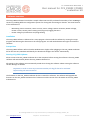
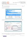
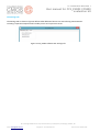
1
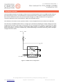
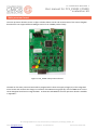
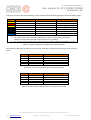
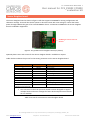
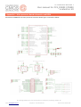
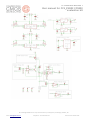
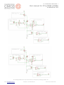
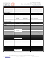
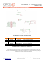
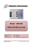
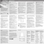
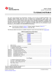
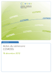
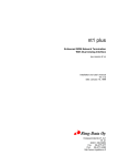
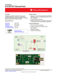
UNAPPROVED CC-000068-DS Revision 1 User manual for CCS_EVK02 CCS800 evaluation kit Evaluation kit for the CCS800 product family of ultra-low power gas sensors Cambridge CMOS Sensors Technology Advantage Key Benefits Our patented CMOS MEMS Micro-hotplates technology provides a unique silicon platform for our Metal Oxide (MOX) gas sensors and enables sensor miniaturisation, significantly lower power consumption and ultra-fast response times. Our Micro-hotplates are located inside a high reliability silicon membrane and act as heating elements for a MOX based sensing material. The MOX resistance changes on reaction to the target gases and operates at a temperature of between 150°C to 400°C. Through enabling fast cycle times, advanced temperature modulation techniques can be used to ensure maximum sensitivity, stability and gas selectivity, and minimise measurement times. Advanced algorithms support the MOX gas sensors family, for maximum sensitivity, selectivity, drift compensation, and for self-calibration; enabling easy and timely integration into a wide range of applications. Direct connection to PC via USB with simple software GUI for easy setup and data logging Develop low-level firmware and software algorithms for gas sensing specific to application Determine effects of temperature and humidity on the gas sensor Evaluate power consumption for different drive scenarios Perform gas air-flow analysis Product Overview The CCS_EVK02 evaluation kit is designed to allow easy test and development with our CCS800 product family of ultra-low power MOX sensors for monitoring indoor air quality including Carbon Monoxide (CO) and a wide range of Volatile Organic Compounds (VOCs). The evaluation kit includes the following: Main processor board Sensor daughter board (fitted with CCS803 as standard) USB to mini-USB cable Windows based software for set-up, measurement and logging results (CCS_EV02) User guide CCS_EVK02 Evaluation kit (Shown with optional plastics) Applications Indoor air quality monitoring Carbon Monoxide or Toxic gas alarm Alcohol breathalyser Software Interface The CCS_EVK02 evaluation kit includes software to evaluate different modes of operation (DC or pulsed mode), and fully select different configuration options for driving and monitoring our CCS800 devices CCS_EVK02 software GUI © Cambridge CMOS Sensors Ltd, Deanland House, Cowley Road, Cambridge, CB4 0DL, UK Email: [email protected] UNAPPROVED Telephone: +44 1223 395 551 Date Issued: 09 Dec 2014 UNAPPROVED CC-000068-DS Revision 1 User manual for CCS_EVK02 CCS800 evaluation kit Hardware overview The CCS_EVK02 evaluation kit is design to allow easy test and development with our CCS800 product family of ultra-low power gas sensors. The evaluation kit can be operated using a number of different interfaces and data can be collected from the main processor board through I2C or USB to enable ease of integration in consumer applications such as smartphones, tablets and wearable devices. This evaluation kit contains a main processor board, a sensor daughter board and a USB to mini-USB cable. The sensitivity of CCS800 product family to a target gas is optimised by adapting the supply voltage (VH) of the integrated micro-heater, and the gas concentration can be correlated to the change in resistance of the MOX sensing layer (Rs). VH can be set using a low-dropout (LDO) regulator or operated in PWM mode to reduce power consumption. The sensor resistance (Rs) is determined using a series load resistor (RL) and an Analogueto-Digital Converter (ADC). VREF = 1 – 2.5V RL VOUT 1 RS 3 Gas 2 RH VH = 0.85 – 1.4V GND 4 GND Figure 1: CCS801 sensor configuration © Cambridge CMOS Sensors Ltd, Deanland House, Cowley Road, Cambridge, CB4 0DL, UK Email: [email protected] UNAPPROVED Telephone: +44 1223 395 551 Date Issued: 09 Dec 2014 UNAPPROVED CC-000068-DS Revision 1 User manual for CCS_EVK02 CCS800 evaluation kit Main processor board The main processor board as shown in figure 2 below allows control and measurement of the sensor daughter boards which can support different MOX gas sensors from CCS800 product family. Figure 2: CCS_EVK02 main processor board The MCU on the main processor board will be programmed to drive the supply voltage (VH) of the integrated micro-heater and measure the change in resistance of the MOX sensing layer (Rs) of the CCS800 sensor on the sensor daughter board via an integrated ADC. A schematic and BOM for the main processor board is available in Appendix I. © Cambridge CMOS Sensors Ltd, Deanland House, Cowley Road, Cambridge, CB4 0DL, UK Email: [email protected] UNAPPROVED Telephone: +44 1223 395 551 Date Issued: 09 Dec 2014 UNAPPROVED CC-000068-DS Revision 1 User manual for CCS_EVK02 CCS800 evaluation kit Jumpers on the main processor board are colour coded and allow flexible operation as shown in table 1 below Jumper Function JP1 JP2 JP3 JP4 JP5 JP6 JP14 Option 1 (Pins 1:2) Sensor 1 heater drive select Sensor daughter board VRefs Heater 1 voltage sense I2C clock select I2C data select Phone alarm select Heater 1 DC voltage select DC voltage DAC0 output Main processor board CS Dev Kit I2C Dev Kit I2C Main processor board alarm EDAC1 Option 2 (Pins 2:3) PWM 2.048V Sensor daughter board heater Sensor daughter board I2C Sensor daughter board I2C Sensor daughter board alarm DAC1 Note(s): 1. The main processor board has been designed to support multiple heater and sensor 2. voltages for future dual and quad sensor devices on our roadmap. JP7 – 13 and JP15 and JP16 are not required for the CCS801, CCS802 and CCS803 gas sensors Table 1: Jumper setting for CCS_EVK02 main processor board The following tables indicate the pin-out for the I2C connector and USB connector on the main processor board. Pin Function 1 2 3 4 5 Alarm I2C Clock I2C Data 1.8V GND Description Alarm from MCU – Phone Wake Up I2C Clock, driven by phone master I2C Data Phone Power Ground Table 2: Pin-out for I2C connector on main processor board Pin(s) Function Description 1 2 3 4, 5 6 USB Power DD+ GND Screen USB Power USB Data + USB Data Ground Cable Screen Table 3: Pin-out for Mini-USB connector on main processor board © Cambridge CMOS Sensors Ltd, Deanland House, Cowley Road, Cambridge, CB4 0DL, UK Email: [email protected] UNAPPROVED Telephone: +44 1223 395 551 Date Issued: 09 Dec 2014 UNAPPROVED CC-000068-DS Revision 1 User manual for CCS_EVK02 CCS800 evaluation kit Sensor Daughter board The sensor daughter board as shown in figure 3 will also support an EEPROM for storing configuration and calibration settings. There will also be the option to drive the heater with a DC voltage or control the heater power through PWM to the gate of an external MOSFET device. A schematic and BOM for the sensor daughter board is available in Appendix II. CCS803 gas sensor fitted as default Figure 3: CCS_EVK02 sensor daughter board (no plastics) Optional plastic cover with screws for the sensor daughter board is available on request. Table 4 below indicates the pin-out for the Harting connector on the sensor daughter board. Pin(s) Function 1 2 3 4 5 6, 8, 10,12, 14 7 15 19 23 8,9,10,11,12,13,14,16,17, 18,20,21,22,23,24,25,26 I2C SDA I2C SCL EEPROM VDD ALARM VRef GND Sensor1 Heater 1 Power Heater 1 ADC Heater 1 FET Gate NC Description I2C data line I2C clock line Supply voltage for EEPROM Alarm output for future use Sense voltage Ground Sensor 1 analog Output Power connection to heater 1 Analog output to heater1 current sense PWM - Ptype heater FET gate for sensor 1 Not connected1 Note: 1. The connector on the main processor board has been designed to support multiple heater and sensor voltages for future dual and quad sensor devices on our roadmap. Table 4: Pin-out for connector on sensor daughter board © Cambridge CMOS Sensors Ltd, Deanland House, Cowley Road, Cambridge, CB4 0DL, UK Email: [email protected] UNAPPROVED Telephone: +44 1223 395 551 Date Issued: 09 Dec 2014 UNAPPROVED CC-000068-DS Revision 1 User manual for CCS_EVK02 CCS800 evaluation kit Software overview The CCS_EVK02 evaluation kit includes a simple software GUI to fully evaluate functionality of our CCS800 gas sensors by enabling different configuration options for driving and monitoring our devices. The main features of this software are: - Monitoring sensor resistance, sensor current, sensor voltage, Heater resistance, Heater voltage, Heater current, Heater power viewing and (long term) logging functions. Heater voltage cycle definition and programming Installation The CCS_EVK02 software is delivered as a setup program. Please install the software by running the setup program and following the directions in the setup program. You will need administrator rights to install the software. Prerequisites The CCS_EVK02 software will work under Windows XP or higher. After plugging in the CCS_EVK02 evaluation kit for the first time, Windows will identify the board and configure the drivers automatically. Starting CCS_EV02 Software Please connect the CCS_EVK02 evaluation kit to the computer before starting the software. The CCS_EVK02 software will automatically detect the CCS_EVK02 evaluation kit. All settings in the software are automatically stored when closing the software. When starting the software the last settings are loaded. Important: In order to save any measurement data, the log file has to be activated before taking the measurements! The firmware on the CCS_EVK02 evaluation kit has to match the software. The software will upgrade the firmware on the CCS_EVK02 evaluation kit if it detects an older version of the firmware on the CCS_EVK02 evaluation kit. © Cambridge CMOS Sensors Ltd, Deanland House, Cowley Road, Cambridge, CB4 0DL, UK Email: [email protected] UNAPPROVED Telephone: +44 1223 395 551 Date Issued: 09 Dec 2014 UNAPPROVED CC-000068-DS Revision 1 User manual for CCS_EVK02 CCS800 evaluation kit Using CCS_EVK02 Software The main software window is divided in three tabs as follows The Measurement tab The measurement tab as shown in figures 4.1 and 4.2 consists of a graph area and allows users to select several use case mode including: Carbon monoxide alarm Alcohol Breathalyzer Sensor refresh and factory test These modes contain default value for heater voltage pulse setting and the measurement rate. Default mode value and measurement rate setting Figure 4.1: CCS_EVK02 software GUI measurement tab Algorithm parameters for changing sensitivity and baseline adaption levels can also be adjusted by the user as shown below: Each mode has different settings for these parameters. © Cambridge CMOS Sensors Ltd, Deanland House, Cowley Road, Cambridge, CB4 0DL, UK Email: [email protected] UNAPPROVED Telephone: +44 1223 395 551 Date Issued: 09 Dec 2014 UNAPPROVED CC-000068-DS Revision 1 User manual for CCS_EVK02 CCS800 evaluation kit Test data can be logged in a user defined txt file and location per below: Example of test log is shown below: Pressing the start button will start a measurement. Pressing the stop button will stop a measurement. Graphs with real-time data voltage and alarm levels Figure 4.2: CCS_EVK02 software GUI measurement tab Graphs can be zoomed by dragging a box into the desired area. Double clicking or dragging a box from lower © Cambridge CMOS Sensors Ltd, Deanland House, Cowley Road, Cambridge, CB4 0DL, UK Email: [email protected] UNAPPROVED Telephone: +44 1223 395 551 Date Issued: 09 Dec 2014 UNAPPROVED CC-000068-DS Revision 1 User manual for CCS_EVK02 CCS800 evaluation kit right to upper left will undo the zoom. Holding the right mouse button allows to shift a zoomed graph. The Max Points parameter controls the number of measurements shown in the graphs. To reset timing parameters and sensitivity / baseline adaptation their default settings, press the defaults button. Pressing the updates button brings up a dialog which checks for new updates of the software. The traffic light in the top right corner indicates a relative alarm level. If green this indicates a low concentration level for target gas and vice versa for red. Traffic light indicating relative alarm / concentration of target gas © Cambridge CMOS Sensors Ltd, Deanland House, Cowley Road, Cambridge, CB4 0DL, UK Email: [email protected] UNAPPROVED Telephone: +44 1223 395 551 Date Issued: 09 Dec 2014 UNAPPROVED CC-000068-DS Revision 1 User manual for CCS_EVK02 CCS800 evaluation kit The pulse tab The pulse tab as shown in figure 5 defines how the heater voltage is set-up and cycled. Each step has a set duration (Step Interval), the duration of every heater step is set in number of step interval units, and the total number of cycle intervals is defined in count. For each cycle interval, the duration and the heater voltage can be set. The graph in the top right, below shows a summary of a programmed heater voltage waveform. Figure 5: CCS_EVK02 software GUI pulse tab Attention: Do not set heater voltages in excess of 2.5V as this will damage the sensor! © Cambridge CMOS Sensors Ltd, Deanland House, Cowley Road, Cambridge, CB4 0DL, UK Email: [email protected] UNAPPROVED Telephone: +44 1223 395 551 Date Issued: 09 Dec 2014 UNAPPROVED CC-000068-DS Revision 1 User manual for CCS_EVK02 CCS800 evaluation kit The Settings tab The Settings tab as shown in figure 6 defines what additional sensors are active during measurements including a separate temperature & humidity sensor and a pressure sensor. Figure 6: CCS_EVK02 software GUI settings tab © Cambridge CMOS Sensors Ltd, Deanland House, Cowley Road, Cambridge, CB4 0DL, UK Email: [email protected] UNAPPROVED Telephone: +44 1223 395 551 Date Issued: 09 Dec 2014 UNAPPROVED CC-000068-DS Revision 1 User manual for CCS_EVK02 CCS800 evaluation kit Technical Specification The technical specification for the CCS_EVK02 evaluation kit is shown in table 5 below: Operating Condition Supply voltage Power consumption Ambient temperature Ambient humidity 5V, 400mA, DC. – Directly PC USB interface <1W 0°C to 40°C 0 to 95% RH non condensing Interface Digital interface Devices supported Software requirements Physical Main processor board dimensions Sensor daughter board dimensions Weight USB 2.0 and I2C CCS801, CCS802 and CCS803 CCS_EVK02 (requires Windows XP SP3 or later) 77mm by 100mm 23mm by 27mm 122g Table 5: CCS_EVK02 technical specification Ordering Information Additional CCS800 sensor daughter boards are available to order as follows: Product Description Target Gases Part Number CCS801 daughter board VOCs, CO and Ethanol CCS_EVK02_801SB CCS802 daughter board CO CCS_EVK02_802SB CCS803 daughter board Ethanol CCS_EVK02_803SB Table 6: Ordering Information © Cambridge CMOS Sensors Ltd, Deanland House, Cowley Road, Cambridge, CB4 0DL, UK Email: [email protected] UNAPPROVED Telephone: +44 1223 395 551 Date Issued: 09 Dec 2014 UNAPPROVED CC-000068-DS Revision 1 User manual for CCS_EVK02 CCS800 evaluation kit Appendix I – Main processor board schematics and BOM Schematics and BOM for the main processor board are shown figure 7 and table 7 below: © Cambridge CMOS Sensors Ltd, Deanland House, Cowley Road, Cambridge, CB4 0DL, UK Email: [email protected] UNAPPROVED Telephone: +44 1223 395 551 Date Issued: 09 Dec 2014 UNAPPROVED CC-000068-DS Revision 1 User manual for CCS_EVK02 CCS800 evaluation kit © Cambridge CMOS Sensors Ltd, Deanland House, Cowley Road, Cambridge, CB4 0DL, UK Email: [email protected] UNAPPROVED Telephone: +44 1223 395 551 Date Issued: 09 Dec 2014 UNAPPROVED CC-000068-DS Revision 1 User manual for CCS_EVK02 CCS800 evaluation kit © Cambridge CMOS Sensors Ltd, Deanland House, Cowley Road, Cambridge, CB4 0DL, UK Email: [email protected] UNAPPROVED Telephone: +44 1223 395 551 Date Issued: 09 Dec 2014 UNAPPROVED CC-000068-DS Revision 1 User manual for CCS_EVK02 CCS800 evaluation kit © Cambridge CMOS Sensors Ltd, Deanland House, Cowley Road, Cambridge, CB4 0DL, UK Email: [email protected] UNAPPROVED Telephone: +44 1223 395 551 Date Issued: 09 Dec 2014 UNAPPROVED CC-000068-DS Revision 1 User manual for CCS_EVK02 CCS800 evaluation kit Figure 7: Schematic(s) for main processor board © Cambridge CMOS Sensors Ltd, Deanland House, Cowley Road, Cambridge, CB4 0DL, UK Email: [email protected] UNAPPROVED Telephone: +44 1223 395 551 Date Issued: 09 Dec 2014 UNAPPROVED CC-000068-DS Revision 1 User manual for CCS_EVK02 CCS800 evaluation kit Ref SENSORBOARD JP1 – JP16 RI, RI1, RI2, RI3 C1,C7,C13,C14,C15,C17,C20,C22, C23,C32,C33, C34, C35, C36, C37, C38,C39, C40, C41,C44 C90 C10, C16, C29, C30 Q1 C71, C72 R1, R2, R3, R4, R5, R6, R7, R8, R9, R10, R13, R14,R22, R27, R28, R29 C2,C3,C4,C5,C6,C8,C9, C11,C12,C18,C19,C21,C24, C25,C26,C27,C31,C42,C43 PHONE_I2C R11, R15, R18, R20, R24, R30, R32, R35 R12, R16, R17, R19, R25, R26, R33, R34 R73 R21, R23, R31, R36 Manufacturer Part number Harting 15 25 026 2601 000 WURTH ELEKTRONIK 61300311121 BOURNS CR0805-FX-1R00ELF 1Ω Resistor in 0805 package MULTICOMP MC0402X104K100CT 100nF Capacitor in 0402 package MULTICOMP MC0603B103K160CT 10nF Capacitor in 0603 package MULTICOMP MCCA000091 10pF Capacitor in 0402 package AKER C6S-12.000-12-3030-X CRYSTALCTS406 12 MHz Crystal MULTICOMP MC0402N120J500CT WELWYN ASC0402-1K0FT10 MULTICOMP MCCA000506 MOLEX 22-27-2051 MULTICOMP MCMR04X2203FTL 220k Resistor in 0402 package VISHAY DRALORIC CRCW040222K0FKEAHP 22k Resistor in 0402 package KOA SG73S1JTTD3303F 330k Resistor in 0603 package YAGEO (PHYCOMP) RC0402JR-0733KL 33k Resistor in 0402 package C45, C28 C46, C47 MULTICOMP R37 – R44 Description Sensor board connector Various coloured jumpers 12pF Capacitor 1K Resistor in 0402 package 1uF Capacitor in 0402 package Connector for phone I2C MCCA000563 4,7uF Capacitor in 1206 package MCCA000603 10uF Capacitor in 1206 package MCMR04X4701FTL 4k7 Resistor in 0402 package Atmel ATXMEGA128A3U Processor in a TQFP64 package MULTICOMP BCX54 IC13 TEXAS INSTRUMENTS DAC8554IPWG4 L1, L2 WURTH ELEKTRONIK 742843122 TDK MLP2012S4R7MT IC1 T1, T3, T5, T7 L3 IC3 TEXAS INSTRUMENTS IC7 IC4 T2, T4, T6, T8 IC6, IC9, IC10, IC12 IC5, IC8 S1 IC2, IC11 LM2937IMP-3.3 LM4128BMF-2.5/NOPB 500mA and 0.38 Ohm 4.7uH Inductor 3.3V LDO Voltage Reference IC LT1129CST-5#PBF Adjustable LDO NXP NX2301P P Type Mosfet TEXAS INSTRUMENTS OPA4344EA/250 NXP PCA9517ADP SENSIRION SHT21 TEXAS INSTRUMENTS SN74AVC4T245PW LITTELFUSE SP0503BAHTG USB FCI 10033526-N3212MLF LED1 WURTH ELEKTRONIK LED2 DAC IC LINEAR TECHNOLOGY DN2 LED3 NPN Transistor in SOT-89 package Op Amp I2C bus repeater Temperature and Humidity Sensor Voltage Level Shifter USB protection diodes Mini USB Connector 150060GS75000 Green LED in a 0603 package 150060RS75000 Red LED in a 0603 package 150060YS75000 Yellow LED in a 0603 package Table 7: Bill-of-Materials (BOM) for sensor daughter board © Cambridge CMOS Sensors Ltd, Deanland House, Cowley Road, Cambridge, CB4 0DL, UK Email: [email protected] UNAPPROVED Telephone: +44 1223 395 551 Date Issued: 09 Dec 2014 UNAPPROVED CC-000068-DS Revision 1 User manual for CCS_EVK02 CCS800 evaluation kit Appendix II – Sensor daughter board schematics and BOM A schematic and BOM for the sensor daughter board is shown figure 8 and table 7 below: Table 4: Pin-out for connector on Sensor Daughter board Figure 8: Schematic for CCS801 sensor daughter board Ref J1 IC1 Q1 R1 R2 S1 C1 JP1 Manufacturer Part number HARTING MICROCHIP NXP MULTICOMP MULTICOMP CCS MULTICOMP WURTH ELEKTRONIK 15 15 026 2601 000 24AA02-I/MS NX2301 MCMR04X1003FTL MCMR04X000 PTL CCS801 MC0402X104K100CT 61300311121 Description Male surface mount connector EEPROM with I2C address 1010000 P Type Mosfet in SOT23 package 100KΏ Resistor in 0402 package 0Ώ Resistor in 0402 package Ultra-low power multi gas sensor 100nF capacitor in 0402 package Jumper to select between DC and FET heater drive Table 8: Bill-of-Materials (BOM) for sensor daughter board The contents of this document are subject to change without notice. CCS products are not designed, authorized or warranted to be suitable for use in medical, military, aircraft, space or life support equipment, nor in applications where failure or malfunction of an CCS product can reasonably be expected to result in personal injury, death or severe property or environmental damage. CCS accepts no liability for inclusion and/or use of CCS products in such equipment or applications and therefore such inclusion and/or use, is at the customer’s own risk. As any devices operated at high temperature have inherently a certain rate of failure, it is therefore necessary to protect against injury, damage or loss from such failures by incorporating appropriate safety measures. © Cambridge CMOS Sensors Ltd, Deanland House, Cowley Road, Cambridge, CB4 0DL, UK Email: [email protected] UNAPPROVED Telephone: +44 1223 395 551 Date Issued: 09 Dec 2014