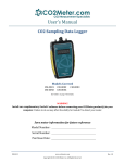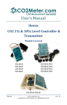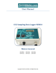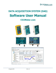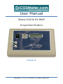
1
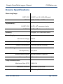
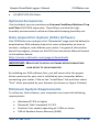
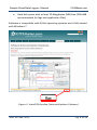
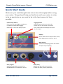
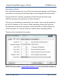
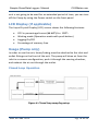
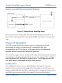
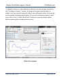
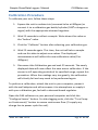
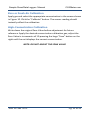
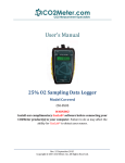
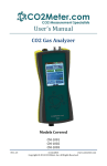
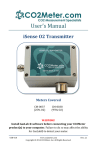
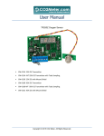
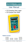
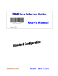
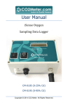
User Manual iSenseCO2&O2MAP InspectionStation CM‐0174 Copyright © 2013 CO2 Meter. All Rights Reserved. Sample Draw/Data Logger– Manual CO2Meter.com Table of Contents TABLE OF CONTENTS .....................................................................................2 WELCOME!....................................................................................................3 IMPORTANT SAFEGUARDS.............................................................................4 DEVICE SPECIFICATIONS ................................................................................5 PACKAGE CONTENTS .....................................................................................6 OPTIONAL ACCESSORIES ........................................................................................ 7 DATA ACQUISITION SYSTEM (DAS) SOFTWARE .......................................................... 7 MINIMUM SYSTEM REQUIREMENTS ......................................................................... 7 QUICK START GUIDE ......................................................................................9 POWER SOURCE ................................................................................................. 11 SETUP .............................................................................................................. 11 POWERING THE UNIT .......................................................................................... 15 LCD DISPLAY (IF APPLICABLE) ............................................................................... 16 USAGE (PUMP ONLY) .......................................................................................... 16 THEORY OF OPERATION ....................................................................................... 17 CALIBRATION ..................................................................................................... 17 CALIBRATING USING MODBUS OR PC CONNECTION ................................................ 18 CALIBRATION PROCEDURE .................................................................................... 21 TROUBLESHOOTING GUIDE ................................................................................... 23 SUPPORT..................................................................................................... 23 WARRANTY ................................................................................................. 24 RETURNS..................................................................................................... 24 LIABILITY ..................................................................................................... 25 CONTACT US ............................................................................................... 25 Rev. 26 Jan. 2013 Pg. 2 of 25 Sample Draw/Data Logger– Manual CO2Meter.com Welcome! Thank you for purchasing our product. This portable meter allows you to measure carbon dioxide and oxygen in inaccessible areas. The iSense CO2 and Oxygen Modified Atmosphere Packaging Inspection Station is designed quickly measure head‐space or internal packaging gas levels. Building on our knowledge of gas sensing technology, this unit combines a high‐accuracy NDIR CO2 sensor with an ultra‐stable Zirconium oxygen sensor to provide accurate measurements of both of the detectable major atmospheric composition gases. This makes the unit perfect for applications like MAP or CAS monitoring and control. Additional features include a built‐in sampling pump, real‐time LED readout, and built‐in data logging. Levels out of range provide both audible and visual signals. It includes front and back gas inlet and outlet ports, continuous or single samples, and optional data out to a 4‐20mA or RS‐485 over MODBUS network. Our goal is to make high‐quality, low‐cost gas detection and indoor air quality products available to you. Please take some time to read through this manual in order to get the most out of your meter. Make sure to visit our website regularly to find more information about this product and to download the DAS software free. Once you download and install the DAS software, you can use the “Check for updates” function under the Help menu to search for new updates. Please also pay special attention to the important safeguards shown on the pages ahead. Rev. 26 Jan. 2013 Pg. 3 of 25 Sample Draw/Data Logger– Manual CO2Meter.com Important Safeguards To reduce the risk of fire, electrical shock and/or injury to persons, basic safety precautions should always be followed when using electrical appliances, including the following: 1. READ ALL INSTRUCTIONS BEFORE USING THIS DEVICE! 2. Use only the supplied power supply to operate the unit. 3. Ensure that when sampling in a closed environment that the tubes are securely fashioned to the device. 4. Do not operate with a blocked off sample path. 5. Do not operate the device if it is malfunctioning. 6. Do not install the device outside in exposed conditions. Due to the nature of the design the enclosure cannot be made water‐ tight and the unit must not be exposed to water. 7. Do not operate the device with the cover detached. SAVE THESE INSTRUCTIONS! Rev. 26 Jan. 2013 Pg. 4 of 25 Sample Draw/Data Logger– Manual CO2Meter.com Device Specifications Measuring Range: 100% CO2 0‐100% vol. (0‐1,000,000 ppm) 25% O2 0‐5%, 0‐65%, or 100% vol. Repeatability: 0‐100% CO2 ±0.5%, ±3% measured value 0‐25% O2 ±0.5%, ±3% of measured value Accuracy ±50ppm, ±3% measured value Power Supply: Maximum Voltage 24VDC Minimum Voltage 20VDC Power Consumption ~5W avg. (pump running) Sensor Ratings: Life Expectancy >15 years Maintenance Interval No maintenance required Warm‐up Time <15 min (instant measurements) Pump Characteristics: Maximum Flow (STP) 1.80 LPM Maximum Vacuum ‐400 mbar / 0.80 LPM Maximum Pressure 370 mbar / 0.70 LPM Rev. 26 Jan. 2013 Pg. 5 of 25 Sample Draw/Data Logger– Manual CO2Meter.com Maximum Flow (STP) 1.80 LPM Outputs: CO2 & O2 Output Value 4‐20 mA, linearly scaled RS‐485 Modbus Interface Relay COM, NO 1A @ 30 VDC (programmable) Package Contents Please verify that your package contains the following items before using the meter: MAP units: (1) Meter (1) Certificate of Calibration (1) User Manual (1) Power supply (1) 6‐foot USB Cable (1) 10‐foot length 1/8” tubing (1) 10‐foot length 3/32” tubing (2) 1/8” Barb tubing bulkhead fitting (2) 1/8” Barb tubing lure head fitting (2) 1/8” Barb 10‐32 fittings (2) Particle Filter (CM‐0118) (2) Hydrophobic Filter (CM‐0117) (2) Moisture Trap (CM‐0112) (1) Hypodermic Needle Kit (CM‐00175) (1) MDCM‐4FP‐2M Cable Rev. 26 Jan. 2013 Pg. 6 of 25 Sample Draw/Data Logger– Manual CO2Meter.com (1) MDCP‐8FP‐2M Cable Optional Accessories If not included, you can purchase an Extreme Conditions Moisture Trap and Filter (CM‐0103) separately. These filters are ideal for high‐ humidity environments to allow air flow while keeping humidity out. Data Acquisition System (DAS) Software Visit CO2Meter.com and go to the “Downloads” page (see link below) to download our DAS software free or for more information on how to connect, configure, and calibrate your meter. For general information about the program, please see the DAS User Instruction Manual located in the website below. http://www.co2meter.com/pages/downloads IMPORTANT: MAKE SURE TO INSTALL SOFTWARE BEFORE CONNECTING YOUR DEVICE TO YOUR COMPUTER By installing our DAS software first, you will ensure that the proper driver necessary for your unit is installed on your computer before connecting your meter. Click on the “Install Now” link and then select “Run” when prompted by your browser (as shown on Figure 1 below). Minimum System Requirements To utilize our free software, your computer must meet the following requirements: Windows XP SP3 or higher Microsoft .Net Framework 3.5 SP1 Pentium 4 (or newer) operating at 2.4Ghz or faster 1GB of Random Access Memory (RAM) Rev. 26 Jan. 2013 Pg. 7 of 25 Sample Draw/Data Logger– Manual CO2Meter.com Hard disk space with at least 20 Megabytes (MB) free (200+MB recommended for logs and application files) Software is compatible with 64‐bit operating systems and is fully tested with Windows 7. Figure 1: Install DAS online (Internet Explorer 9 shown) Rev. 26 Jan. 2013 Pg. 8 of 25 Sample Draw/Data Logger– Manual CO2Meter.com Quick Start Guide Make sure you read through these instructions thoroughly before using your meter. This guide will help you familiarize with your meter in order to be as productive as you need to be in the least amount of time possible. Power Pump Switch If the unit has data logging capabilities, it disables/enables data logging. Otherwise, it turns the pump on/off. Logging Button Default setting, when you press the button will run the pump a period of time, collect data and display the values of the sample. Display Shows CO2 and O2 concentration levels, data logging status and free space. Barb Fittings Connect to sampling system for closed and open loop sampling. Data / Signal MDCP‐8FP‐2M Cable connector for RS‐485 Modbus and CO2/O2 4‐20 mA. Rev. 26 Jan. 2013 AUX / Relay MDCM‐4FP‐2M Cable connector for 24 VDC and Relay output (COM, NO). Pg. 9 of 25 Sample Draw/Data Logger– Manual CO2Meter.com MDCM-4FP-2M MDCP-8PC-2M Rev. 26 Jan. 2013 Pg. 10 of 25 Sample Draw/Data Logger– Manual CO2Meter.com ON / OFF Switch This switch turns ON and OFF the unit. 24 VDC Input DC barrel connector for the power supply 24 VDC include. USB Port Remove the cap to get access on the USB input. Computer connection. Power Source The unit can be powered by hardwiring 24 VDC power through the MDCM‐4FP‐2M Cable (included) but sampling units can also be powered by the included 24VDC International wall power supply. Setup Our sampling device will require minimal setup since it is designed to be portable. The most important aspect of the setup involves connecting the sampling hoses and ensuring proper environmental setup. Rev. 26 Jan. 2013 Pg. 11 of 25 Sample Draw/Data Logger– Manual CO2Meter.com Sampling Mode This mode the pump will run all the time without stopping, it will display the value in real‐time and will data log in the background continuously. These modes are used for sampling of closed‐loop and open‐loop CO2/O2 systems and collection of real‐time data. There is no initialization required for this mode. Units may be powered by the DC Adapter or DC source. While sampling, these units may be connected to a personal computer and used with our DAS software to record samples or it can be used as a stand‐alone sampling device. These are the setting for this mode: NOTE: Please contact [email protected] for technical assistance. Rev. 26 Jan. 2013 Pg. 12 of 25 Sample Draw/Data Logger– Manual CO2Meter.com Data Logger MAP Mode This mode is a default setting that describes the MAP unit. Feature an internal memory capable storing data when not attached to a personal computer. These units will allow you to simultaneously read and store CO2/O2 concentration level data. Due to the nature of their design, these units should be connected to your personal computer first, before operation, to initialize and set the logging period. Connect the unit to the included power supply. In order to initialize data logging functionality, the unit MUST be connected to the computer with DAS software started. Once the unit has been connected, click on the “Configure Sensor” button in the DAS interface, set the data logging interval and pump periods as desired. We recommend leaving the pump interval to the default 10‐second period. For the pump period, we recommend 10 or more seconds. Figure 2 below shows the available settings. This is the internal configuration of this setting only accessible through Advanced (Password is required). Rev. 26 Jan. 2013 Pg. 13 of 25 Sample Draw/Data Logger– Manual CO2Meter.com Figure 2: Pump & Data Logging Settings The pump PWM period can also be tweaked for advanced applications, with 1 being full duty cycle, and values approaching 255 being the shortest duty cycle. The pump mode should always be set to “Data logging” for proper operation of the unit. All models have an internal coin cell CR‐2032 3V battery backup for the real‐time clock. This battery is inserted in the factory for your convenience and should last the lifetime of the product. Rev. 26 Jan. 2013 Pg. 14 of 25 Sample Draw/Data Logger– Manual CO2Meter.com Figure 3: Collecting data in real time Powering the Unit The unit can be powered by hardwiring 24 VDC power through the MDCM‐4FP‐2M Cable (included) but sampling units can also be powered by the included 24VDC International wall power supply. These units CANNOT be powered from the included USB cable. Testing has shown that USB power tends to produce inconsistent supply voltage and degrades sensor accuracy. In the units with or without data logging, the switch on the back will turn the power ON/OFF for the entire unit. In units with data logging mode, the Push button switch on the front has been dedicated to enabling/disabling data logging. As long as the unit has the power adapter is connected, the unit will be operating. If the Rev. 26 Jan. 2013 Pg. 15 of 25 Sample Draw/Data Logger– Manual CO2Meter.com unit is not going to be used for an extended period of time, you can turn off the Pump by using the Power switch on the front panel. LCD Display (if applicable) The Liquid Crystal Display (LCD) screen shows the following features: CO2 in percentage format (##.##%) for 100% Waiting mode (Operation mode with push button) Logging On/Off Percentage of memory free Usage (Pump only) In order to use the unit, hoses/tubing must be attached to the inlet and outlet fittings on the front of the unit. The pump will draw air from the inlet in a vacuum configuration, push it through the sensing chamber, and exhaust the air out through the outlet. Closed Loop Operation Figure 4: Closed loop sampling setup Rev. 26 Jan. 2013 Pg. 16 of 25 Sample Draw/Data Logger– Manual CO2Meter.com Open Loop with Environmental Exhaust Figure 5: Opened loop sampling setup We recommend installing the included humidity/particulate filter to ensure the sensing chamber and pump baffle stays clear and corrosion free. Theory of Operation The CO2 sensor inside this device uses non‐dispersive infrared technology to sense, as a function of transmitted light, the concentration of CO2 in the air. It has been factory‐calibrated to operate within the specified range and precision. The zirconia oxygen sensor utilizes solid‐state electrochemical reactions to produce a voltage proportional to the current oxygen. This voltage is then digitalized and filtered to a usable value. The oxygen sensor has also been factory calibrated to meet specifications. Calibration The calibration process varies depending on the type of unit and whether it has optional data logging functionality or not. All units are factory‐calibrated with multiple reference points of gas, and have been verified to be accurate within their specific functionality before Rev. 26 Jan. 2013 Pg. 17 of 25 Sample Draw/Data Logger– Manual CO2Meter.com shipment. However, if the unit is severely jolted or otherwise mechanically disturbed, the sensor can drift requiring recalibration. All calibration procedures follow a single‐point calibration routine that effectively shifts the zero‐point of the CO2 and O2 sensor. Calibrating using MODBUS or PC Connection You can Download the software directly and free from this link in our website. (http://www.co2meter.com/pages/downloads) More precise calibrations can be performed using the PC connection. The unit can be attached to a PC using an optional USB to RS‐485 cable, available on our website, or via a mini‐USB cable to the internal USB connection. Calibration of the Oxygen Sensor Rev. 26 Jan. 2013 Pg. 18 of 25 Sample Draw/Data Logger– Manual CO2Meter.com Calibration of the 0‐100% CO2 Sensor In the desktop software application O2 and CO2 can be calibrated individually. The CO2 sensor can be calibrated either with a nitrogen air source to 0%, or using fresh air to 0.04%. The O2 sensor can be calibrated to 0% and then to 20.9%. During normal operation 0% calibration of the oxygen transmitter should not be necessary. Calibration can also be performed over MODBUS, see additional documentation for MODBUS registers. Calibration can be performed using either 0% CO2 calibration gas (typically nitrogen, Argon, etc.), or using a fresh source of air, assumed to be approximately 400ppm. Attach calibration gas to the unit and connect the unit to a personal computer. Open the calibration screen in the DAS software. Click the Rev. 26 Jan. 2013 Pg. 19 of 25 Sample Draw/Data Logger– Manual CO2Meter.com “Calibrate” button in the calibration tab for the desired gas, located in the “Configure Sensor” screen. As long as the gas concentration is stable, the unit should instantly reflect the calibrated value. This can be confirmed by watching the display. To see the calibration value in real time, click in the “Collect Real time” button to capture these values before opening the configuration screen. Real‐time capture Rev. 26 Jan. 2013 Pg. 20 of 25 Sample Draw/Data Logger– Manual CO2Meter.com Calibration Procedure To calibrate your unit, follow these steps: 1. Expose the unit to ambient air (assumed to be at 400ppm) or connect it to a calibration gas bottle/cylinder (100% nitrogen or argon) with the appropriate demand regulator. 2. Wait 25 seconds to collect a sample. Write down this value as the “before” value. 3. Click the “Calibrate” button after selecting your calibration gas. 4. Wait 25 seconds again. This time, the unit will take a sample and use this data to adjust zero values. The displayed measurements will reflect the new calibration value (0 or 400ppm). 5. Disconnect the Calibration gas and wait 25 seconds. The newly displayed data will now reflect the new sensor calibration. If the sensor is still operating outside of its specified range, repeat this procedure. When the readings vary too greatly, the calibration will silently fail and may need to be performed again. To perform a calibration, attach the unit to your computer, power it with the wall adapter and either expose it to atmosphere or supply it with your calibration gas, fed with a demand‐based regulator. Open the DAS software on your personal computer and click the “Configure Sensor” button. For data logging units, click the “Turn Pump on Continuously” button to ensure continuous flow. (To apply any change has to power cycle the unit) Rev. 26 Jan. 2013 Pg. 21 of 25 Sample Draw/Data Logger– Manual CO2Meter.com Zero or Fresh Air Calibration Apply gas and select the appropriate concentration in the screen shown in Figure 10. Click the “Calibrate” button. The sensor reading should instantly reflect the calibration. High-Concentration Calibration Write down the original Zero Value before adjustment for future reference. Apply the desired concentration calibration gas; adjust the Zero Value in increments of 10 pressing the large “Save” button on the right until the unit displays the correct concentration. NOTE: DO NOT ADJUST THE SPAN VALUE. Rev. 26 Jan. 2013 Pg. 22 of 25 Sample Draw/Data Logger– Manual CO2Meter.com Troubleshooting guide Symptom/ Issue PossibleCause/Resolution Device/Sensor isnot recognizedby PC Devicedoesn’t powerON Yourdevice’sbatteriesmightbedepleted.Replace thebatterieswithfreshones,orifapplicable, connectthedevicetotheincludedpowersupply. TheDAS software doesn’tstart* Slowresponse Reading doesn’tchange “Bat”and greenLED keepflashing Makesurethepoweradapterispluggedproperly andthatthereispowerintheoutlettheadapteris connectedhastheappropriatevoltage.Ifusing batteries,makesuretheyarenotdepleted. Yoursoftwaremightbeoutofdate.Updateyour softwarebyeithervisitingourdownloadwebpage athttp://www.co2meter.com/pages/downloads orbyselectingthe“CheckforUpdates”underthe Helpmenu.MakesureyourPCmeetstheminimum requirements. Checktheairflowchannelstomakesuretheyare notobstructed. Makesurethemeterisinmaximumorminimum mode. Thepoweradapteroutputvoltageis inappropriate.Pleaseusethepoweradapterwith correct5V(±10%),≥0.5A. *FormoretroubleshootingtipsonDASsoftware,seeDASmanuallocatedat www.co2meter.com/pages/downloads. Support The quickest way to obtain technical support is via email. Please send all support enquires to [email protected]. In your email, please include a clear, concise definition of the problem and any relevant troubleshooting information or steps taken so far, so we can duplicate the problem and quickly respond to your inquiry. Rev. 26 Jan. 2013 Pg. 23 of 25 Sample Draw/Data Logger– Manual CO2Meter.com Warranty This unit comes with a 1YEAR (warranty period) limited manufacturer’s warranty, starting from the date the unit was shipped to the buyer. During this period of time, CO2Meter.com warrants our products to be free from defects in materials and workmanship when used for their intended purpose and agrees to fix or replace (at our discretion) any part or product that fails under normal use. To take advantage of this warranty, the product must be returned to CO2Meter.com at your expense. If, after examination, we determine the product is defective, we will repair or replace it at no additional cost to you. This warranty does not cover any products that have been subjected to misuse, neglect, accident, modifications or repairs by you or by a third party. No employee or reseller of CO2Meter.com’s products may alter this warranty verbally or in writing. Returns If the product fails under normal use during the warranty period, an RMA (Return Material Authorization) number must be obtained from CO2Meter.com. After the item is received, CO2Meter.com will repair or replace the item at our discretion. To obtain an RMA number, please call CO2Meter.com at (877) 678‐ 4259. When requesting an RMA number, please provide the reason for return and original order number. If we determine that the product failed due to improper use (water damage, dropping, tampering, electrical damage etc.) or abuse, or if it is Rev. 26 Jan. 2013 Pg. 24 of 25 Sample Draw/Data Logger– Manual CO2Meter.com beyond the warranty period, we will inform you of the cost to fix or replace your device. If you are returning your device due to a warranty claim (with an RMA number) and you still have the unit original package, please use it to ship your unit to us. Please make sure to include the provided RMA number on the outside of the box, preferably on the shipping label. Make sure you secure the unit inside the package properly to prevent any damage during transit that could void your device’s warranty. Finally, please ship your device to the address shown under the “Contact Us” section below. CO2Meter.com will not, under any circumstances, be responsible for your shipment expenses and no refund will be issued for shipping charges necessary for you to ship the unit to us. Liability All liabilities under this agreement shall be limited to the actual cost of the product paid to CO2Meter.com. In no event shall CO2Meter.com be liable for any incidental or consequential damages, lost profits, loss of time, lost sales or loss or damage to data, injury to person or personal property or any other indirect damages as the result of use of our products. Contact Us We are here to help! If the troubleshooting guide above doesn’t help you solving your problem or for more information, please contact us using the information below. Rev. 26 Jan. 2013 Pg. 25 of 25 Sample Draw/Data Logger– Manual CO2Meter.com [email protected] (877) 678‐4259 Toll free (M‐F 9:00am–6:00pm EST) (866) 422‐2356 www.co2meter.com Address: CO2Meter 131 Business Center Building A, Unit 3 Ormond Beach, FL 32174 Rev. 26 Jan. 2013 Pg. 26 of 25