1
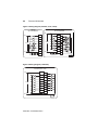
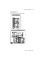
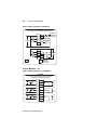
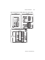
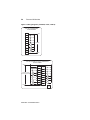
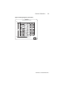
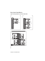
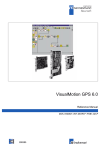
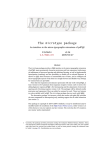
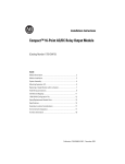
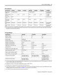
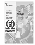
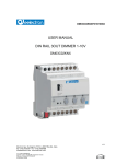
MANUFACTURER DATA SHEET Discrete I/O Manufacturer: Allen-Bradley/Rockwell Model Number: 1746 Series See www.geomartin.com for additional PDF datasheets Martin Part Number: VendorPartNumber: E-014624-02 AB # 1746-IA8, AC Input, 8 Point E-014624-03 AB # 1746-IOA16, AC Output, 16 Point PDF File: Doc_000003_Cover.pdf This page is intentionally left blank Discrete I/O Modules (Catalog Number 1746 Series) Installation Instructions Input Module Catalog Numbers: 1746-IA4, -IA8, -IA16, -IB8, -IB16, -IC16, -IG16, -IH16, -IM4, -IM8, -IM16, -IN16, -ITB16, -ITV16, -IV8, -IV16 Output Module Catalog Numbers: 1746-OA8, -OA16, -OAP12, -OB8, -OB6EI, -OB16, -OB16E, -OBP8, -OBP16, -OG16, -OV8, -OV16, -OVP16, -OW4, -OW8, OW16, -OX8 Combination Input/Output Module Catalog Numbers: 1746-IO4, -IO8, -IO12, -IO12DC Publication 1746-IN005A-US-P 2 Discrete I/O Modules Important User Information Because of the variety of uses for the products described in this publication, those responsible for the application and use of this control equipment must satisfy themselves that all necessary steps have been taken to assure that each application and use meets all performance and safety requirements, including any applicable laws, regulations, codes and standards. The illustrations, charts, sample programs and layout examples shown in this guide are intended solely for purposes of example. Since there are many variables and requirements associated with any particular installation, AllenBradley does not assume responsibility or liability (to include intellectual property liability) for actual use based upon the examples shown in this publication. Allen-Bradley publication SGI-1.1, Safety Guidelines for the Application, Installation, and Maintenance of Solid-State Control (available from your local Allen-Bradley office), describes some important differences between solid-state equipment and electromechanical devices that should be taken into consideration when applying products such as those described in this publication. Reproduction of the contents of this copyrighted publication, in whole or in part, without written permission of Allen-Bradley Company, Inc., is prohibited. Throughout these installation instructions we use notes to make you aware of safety considerations: ! ATTENTION: Identifies information about practices or circumstances that can lead to personal injury or death, property damage or economic loss. Attention statements help you to: • identify a hazard • avoid the hazard • recognize the consequences IMPORTANT: Identifies information that is critical for successful application and understanding of the product. Publication 1746-IN005A-US-P This page is intentionally left blank 38 Discrete I/O Modules Recovery From Blown Fuse/Processor Fault/Processor Shutdown Processor operation will stop under the following conditions: • The output module fuse blows due to a short circuit. • JP1 is set to the Processor Faults position (pins 2 and 3 connected). If the above conditions occur, the following procedures should be used for recovery: 1. Follow fuse replacement procedures shown on page 39. 2. Clear the processor major fault bit S:1/13. 3. Clear processor status file S:6 major error code (optional). 4. Return processor to Run Mode. For additional information on processor fault codes and clearing processor fault bits, refer to the following user manuals: • Your programming device’s reference manual • HHT User Manual, publication 1747-NP002 Chapter 28, Troubleshooting Fault Chapter 29, Understanding the Fault Routine Replacement Fuse Recommendations Use the following replacement fuses • 1746-OBP16/-OVP16 -Littelfuse #322010,10A. This fuse is required to maintain UL/CSA rating. Replacement Fuse Kit is catalog number 1746-F8. (5 fuses per kit). • 1746-OAP12 -Use SAN-O HQ 6.3A for replacement. This fuse is required to maintain UL/CSA rating. Replacement Fuse Kit is catalog number 1746-F9 (5 fuses per kit). Publication 1746-IN005A-US-P Discrete I/O Modules 39 Fuse Replacement Procedure To replace a blown fuse: ! ATTENTION: Never install, remove, or wire modules with power applied to chassis. 1. Remove SLC 500 system power and correct the conditions causing the short circuit. 2. Remove the output module from the chassis. 3. Remove the fuse. • 1746-OBP16/-OVP16: Use a wide tipped, slotted head screw driver to remove the blown fuse. Slide the screw driver tip under the fuse and use a twisting motion to pry the fuse from the fuse clip. Use care so that the printed circuit board and surrounding electronics are not damaged. • 1746-OAP12: A fuse holder is provided with each fuse. Simply grasp the fuse holder with needle-nose pliers, or your fingers, and pull it out. 4. Replace the fuse. • 1746-OBP16/OVP16: Center the replacement fuse over the fuse clip and press down. If a tool is used to press the fuse in place, apply pressure to the metal end caps only, not the center of the fuse. • 1746-OAP12: Insert a new fuse into the fuse holder, align fuse holder on fuse clips and press down. 5. Replace the output module in the chassis. 6. Restore SLC 500 system power. Clear processor fault bits as indicated in the steps provided on page 38. Publication 1746-IN005A-US-P 40 Discrete I/O Modules Electronically Protected Modules (1746-OB6EI and OB16E) Electronic Protection The electronic protection of the 1746-OB6EI and -OB16E has been designed to provide protection for the modules from short circuit and overload current conditions. The protection is based on a thermal cut-out principle. In the event of a short circuit or overload current condition on an output channel, that channel will limit current within milliseconds after its thermal cut-out temperature has been reached. All other channels continue to operate as directed by the CPU (processor) module. IMPORTANT: The modules do not provide protection against reverse polarity wiring or wiring to AC power sources. Electronic protection is not intended to replace fuses, circuit breakers, or other code-required wiring protection devices. OUTPUT OUTPUT EE FF UU SS EE Front View Publication 1746-IN005A-US-P EFUSE LED Note: There is no jumper setting on this module Discrete I/O Modules 41 Auto Reset Operation IMPORTANT: The 1746-OB6EI and -OB16E perform auto-reset under overload conditions. When an output channel overload occurs as described on page 40, that channel will limit current within milliseconds after its thermal cut-out temperature has been reached. While in current limit, the output channel can cool below the thermal cutout temperature allowing the module to auto-reset and resume control of the output channel as directed by the processor until the thermal cut-out temperature is again reached. Removing power from an overloaded output channel would also allow the output channel to cool below the thermal cut-out temperature, allowing auto-reset to occur when power is restored. The output channel would operate as directed by the processor until the thermal cut-out temperature is again reached. To avoid auto-reset of an output channel under overload conditions, an external mechanical fuse can be used to open the circuit when overloaded. Short Circuit/Overload Current Diagnostics If a short circuit or overload current condition occurs on an output channel: 1. The E-Fuse LED will illuminate provided that power is applied to the module. Power required: 5V dc via backplane and load power via an external supply. 2. All other channels continue to operate as directed by the CPU (processor) module. Recovery From Channel Shutdown 1. Remove the SLC 500 system power and correct the conditions causing the short circuit or overload current condition. 2. Restore the SLC 500 system power. The module automatically resets and resumes control of the output channel and associated load. Publication 1746-IN005A-US-P 42 Discrete I/O Modules Wiring Diagrams The wiring diagrams in these installation instructions are examples only. It is not necessary to connect an I/O device to each and every I/O module terminal. Labeling for SLC/PLC® Systems In this document, 16-point I/O module wiring diagrams include both decimal and octal numbers for I/O addressing and wire identification (see figure below). To wire your 16-point I/O module when used in a SLC system, use the decimal numbers in the upper left portion of each box. When used in a PLC system, use the octal numbers in the lower right portion of the box. As shipped from the factory, the I/O module has a decimal address label on the inside of its door. An octal label kit should be included with your 16-point I/O modules, or a separate octal conversion kit can be ordered, to allow you to convert your module to the octal system. IMPORTANT: Ensure the octal labels are used with your PLC system. Directions on how to install the labels are included with the kit and on page 30 of this document. Figure 6:Decimal and Octal Labeling for 16-Point I/O Modules L1 1746-IA16 100/120V ac IN 0 For SLC (decimal) 0 IN 1 2 IN 3 4 IN 5 1 IN 2 3 IN 4 IN 14 5 IN 6 100/120V ac 16 6 IN 7 10 IN 9 12 IN 11 7 IN 8 11 IN 10 13 IN 12 For PLC (octal) 14 IN 13 15 IN 14 16 IN 15 L2 17 AC COM AC COM COMMONS CONNECTED INTERNALLY Publication 1746-IN005A-US-P SLC PLC Discrete I/O Modules 43 Input Modules - ac Figure 7:Wiring Diagrams (1746-IA4, -IA8, -IA16) 1746-IA8 100/120V ac 1746-IA4 100/120V ac L1 NOT USED IN 1 NOT USED IN 2 NOT USED L1 100/120V ac IN 0 NOT USED IN 3 100/120V ac IN 0 IN 4 IN 1 IN 5 IN 2 IN 6 IN 7 IN 3 L2 AC COM AC COM L2 COMMONS CONNECTED INTERNALLY AC COM 1746-IA16 100/120V ac L1 IN 0 0 IN 1 2 IN 3 4 IN 5 1 IN 2 3 IN 4 5 IN 6 100/120V ac 6 IN 7 10 IN 9 7 IN 8 11 IN 10 12 IN 11 14 IN 13 13 IN 12 IN 14 15 16 IN 15 L2 17 AC COM AC COM COMMONS CONNECTED INTERNALLY SLC PLC Publication 1746-IN005A-US-P 44 Discrete I/O Modules Figure 8:Wiring Diagrams (1746-IM4, -IM8, -IM16) 1746IM4 200/240V ac 1746-IM8 200/240V ac L1 NOT USED IN 0 NOT USED IN 1 NOT USED IN 2 NOT USED L1 IN 3 200/240V ac IN 0 IN 4 IN 1 200/240V ac IN 5 IN 2 IN 6 IN 3 L2 IN 7 L2 AC COM AC COM COMMONS CONNECTED INTERNALLY 1746-IM16 200/240V ac L1 IN 0 0 IN 1 2 IN 3 4 IN 5 1 IN 2 3 IN 4 200/240V ac 5 IN 6 6 IN 7 10 IN 9 7 IN 8 11 IN 10 12 IN 11 14 IN 13 13 IN 12 15 IN 14 16 IN 15 L2 17 AC COM AC COM COMMONS CONNECTED INTERNALLY Publication 1746-IN005A-US-P SLC PLC AC COM Discrete I/O Modules 45 Input Modules - dc Figure 9:Wiring Diagram (1746-IN16) 1746-IN16 24V ac/dc SINKING L1 or +DC IN 0 0 IN 1 2 IN 3 1 IN 2 3 IN 4 4 IN 6 V ac/dc IN 5 5 6 IN 7 7 IN 8 10 IN 9 11 IN 10 12 IN 11 13 IN 12 14 IN 13 15 16 IN 15 17 AC/DC COM AC/DC COM IN 14 L2 or -DC COMMONS CONNECTED INTERNALLY SLC PLC Figure 10:Wiring Diagram (1746-IB8, -IB16, -ITB16, -IC16, -IH16) 1746-IB8 24V dc SINKING 1746-IB16, -ITB16 24V dc SINKING 1746-IC16 1746-IH16 48V dc SINKING 125V dc SINKING +DC +DC IN 0 IN 0 IN 1 IN 2 IN 2 IN 3 24V dc 24V dc (IB16, ITB16) 48V dc (IC16) IN 4 IN 5 COMMONS CONNECTED 1 2 IN 3 3 IN 4 4 IN 5 5 6 IN 7 7 6 10 IN 9 11 IN 10 IN 6 IN 8 125V dc (IH16) 12 IN 11 IN 6 IN 12 IN 7 IN 14 DC COM ±DC 0 IN 1 ±DC 13 14 IN 13 15 16 IN 15 DC COM 17 DC COM DC COM COMMONS CONNECTED SLC PLC Publication 1746-IN005A-US-P 46 Discrete I/O Modules Figure 11:Wiring Diagram (1746-IV8, -IV16, -ITV16) 1746-IV8 24V dc SOURCING 1746-IV16, -ITV16 24V dc SOURCING ±DC ±DC IN 0 IN 0 3 6 IN 7 10 IN 9 24V dc IN 5 IN 10 IN 6 IN 12 11 12 IN 11 13 14 IN 13 IN 14 +DC VDC 5 7 IN 8 IN 4 15 16 IN 15 17 VDC VDC VDC CONNECTED INTERNALLY VDC VDC CONNECTED INTERNALLY Figure 12:Wiring Diagram (1746-IG16) 1746-IG16 TTL INPUT (Low = True) +5 DC IN 0 0 IN 1 1 IN 2 3 IN 4 5 IN 6 7 IN 8 2 IN 3 4 IN 5 6 IN 7 +5V dc 1 4 IN 5 IN 7 +DC IN 3 IN 6 IN 3 +DC IN 1 2 IN 4 IN 2 24V dc 0 IN 2 IN 1 10 IN 9 11 IN 10 12 IN 11 13 IN 12 IN 13 14 15 IN 14 IN 15 16 17 DC COM ±DC SLC PLC Publication 1746-IN005A-US-P SLC PLC Discrete I/O Modules 47 Output Modules - ac Figure 13:Wiring Diagrams (1746-OA8, -OA16) 1746-OA8 100 to 240V ac TRIAC OUTPUT L1 VAC 1 OUT 0 100-240V ac OUT 1 CR OUT 2 L2 CR OUT 3 L1 VAC 2 OUT 4 100-240V ac OUT 5 OUT 6 CR OUT 7 CR L2 1746-OA16 100 to 240V ac TRIAC OUTPUT L1 VAC 1 OUT0 0 OUT 1 1 OUT 2 2 OUT 3 100-240V ac 3 OUT 4 CR CR 4 OUT 5 CR 5 OUT 6 CR 6 OUT 7 7 L2 L1 VAC 2 OUT 9 11 OUT 8 10 OUT 11 13 OUT 10 CR CR 15 OUT 12 14 OUT 15 17 OUT 14 16 SLC PLC 100-240V ac 12 OUT 13 CR CR L2 Publication 1746-IN005A-US-P 48 Discrete I/O Modules Figure 14:Wiring Diagram (1746-OAP12) 1746-OAP12 100 to 240V ac HIGH CURRENT TRIAC OUTPUT COMMONS CONNECTED INTERNALLY VAC 1 L1 VAC 1 OUT 1 1 CR 100-240V ac CR OUT 3 OUT 5 OUT 0 0 3 OUT 2 5 OUT 4 NOT USED 2 4 CR NOT USED L2 L2 OUT 7 CR CR 7 OUT 6 6 11 OUT 8 10 OUT 11 13 OUT 10 12 VAC 2 VAC 2 OUT 9 100-240V ac CR L1 COMMONS CONNECTED INTERNALLY SLC PLC Output Modules - dc Figure 15:Wiring Diagrams (1746-OB6EI) 1746-OB6EI 10-30V dc TRANSISTOR OUTPUT-SOURCING CHANNEL-TO-CHANNEL ISOLATED VDC 1 +DC 10-30V dc CR -DC DC COM 1 +DC VDC 3 10-30V dc CR DC COM 3 +DC VDC 5 -DC CR +DC OUT 0 10-30V dc DC COM 0 -DC VDC 2 +DC OUT 2 10-30V dc DC COM 2 -DC VDC 4 +DC OUT 4 10-30V dc DC COM 4 -DC OUT 3 -DC 10-30V dc VDC 0 OUT 1 OUT 5 DC COM 5 Publication 1746-IN005A-US-P Discrete I/O Modules 49 Figure 16:Wiring Diagrams (1746-OB8, -OBP8, -OB16, -OB16E, -OBP16) 1746-OB8 10 to 50V dc Transistor Output-Sourcing 1746-OBP8 20.4 to 26.4V dc Transistor Output-Sourcing +DC VDC1 OUT 0 VDC +DC +DC CR OUT 1 CR OUT 3 OUT 2 OUT 0 20.4-26.4V dc OUT 1 NC OUT 2 NC DC COM1 NC OUT 3 10-50V dc OUT 4 CR OUT 5 CR -DC NC OUT 6 OUT 7 NC NC +DC CR VDC2 OUT 4 CR DC COM CR OUT 5 CR OUT 7 OUT 6 20.4-26.4V dc -DC DC COM2 -DC 1746-OB16, 1746-OB16E, -OBP16 10 to 50V dc, 10 to 30V dc, 20.4 to 26.4V dc Transistor Output-Sourcing +DC VDC 0 OUT 2 1 2 OUT 3 10-50V dc (OB16) 10-30V dc (OB16E) 20.4-26.4V dc (OBP16) CR 3 OUT 4 5 OUT 6 7 OUT 8 4 OUT 5 6 OUT 7 OUT 9 10 11 OUT 10 CR 13 OUT 12 14 OUT 13 15 OUT 14 16 OUT 15 CR CR 12 OUT 11 CR PLC OUT 0 OUT 1 CR SLC CR CR 17 DC COM -DC Publication 1746-IN005A-US-P 50 Discrete I/O Modules Figure 17:Wiring Diagrams (1746-OV8, -OV16, -OVP16) 1746-OV8 10 to 50V dc TRANSISTOR OUTPUT SINKING VDC +DC OUT 0 OUT 1 OUT 2 OUT 3 10-50V dc OUT 4 CR OUT 5 CR OUT 6 OUT 7 CR CR DC COM -DC 1746-OV16, -OVP16 10 to 50V dc OR 20.4 to 26.4V dc TRANSISTOR OUTPUT SINKING +DC VDC OUT 0 0 OUT 1 1 OUT 2 3 OUT 4 5 OUT 6 7 OUT 8 2 OUT 3 10-50V dc (OV16) 20.4-26.5V dc (OVP16) CR 4 OUT 5 OUT 7 CR 6 CR 10 OUT 9 11 OUT 10 12 OUT 11 13 OUT 12 15 OUT 14 14 OUT 13 CR CR OUT 15 -DC 17 16 CR CR CR DC COM SLC PLC Publication 1746-IN005A-US-P Discrete I/O Modules 51 Figure 18:Wiring Diagrams (1746 -OG16) 1746-OG16 TTL OUTPUT (Low = True) +DC VDC L OUT 0 L OUT 1 L OUT 3 0 1 OUT 2 +5V dc L OUT 5 L OUT 7 L OUT 9 L OUT 11 L OUT 13 L -DC L 2 3 OUT 4 L 4 5 OUT 6 7 OUT 8 L 6 L 10 11 OUT 10 12 13 OUT 12 14 15 OUT 14 16 OUT 15 L L L 17 DC COM SLC PLC Publication 1746-IN005A-US-P 50 Discrete I/O Modules Figure 17:Wiring (1746-OV8, -OV16, -OVP16) Relay Contact Diagrams Output Modules Figure 19:Wiring Diagrams (1746 -OW4, -OW8, -OW16) 1746-OV8 10 to 50V dc TRANSISTOR OUTPUT SINKING 1746-OW4 RELAY OUTPUT VDC 1746-OW8 RELAY OUTPUT +DC OUT 0 VAC-VDC OUT 0 V ac/dc OUT 2 OUT 1 CR OUT 4 OUT 3 CR L1+DC or +DC 10-50V dc CR L2 or -DC CR OUT 3 CR VAC-VDC 2 CR OUT 4 CR L2 or -DC L1 or +DC V ac/dc OUT 5 -DC OUT 6 CR OUT 7 CR L2 or -DC 1746-OV16, -OVP16 10 to 50V dc OR 20.4 to 26.4V dc TRANSISTOR 1746-OW16 OUTPUT SINKING RELAY OUTPUT 10-50V dc (OV16) CR 20.4-26.5V dc (OVP16) CR CR CR VAC-VDC OUT0 VDC 1 0 OUT 1 OUT1 2 1OUT 21 OUT 3 34 OUT 3OUT OUT 5 43 5 6 OUT 5OUT 65 OUT 7 7OUT 7 7 OUT 0 0 OUT 2 2 CR OUT 4 4 OUT 6CR 6 OUT 8 CR 10 L2 or -DC CR CR SLC OUT 2 CR V ac/dc -DC V ac/dc OUT 1 OUT 3 OUT 2 NOT OUT 5 USED NOT OUT 6 USED NOT OUT 7 USED DC COM NOT USED OUT 7 NOT USED L1 or +DC VAC-VDC 1 L1 or +DC OUT 1 OUT 0 OUT 9 VAC-VDC 11 OUT 10 OUT 9 OUT 112 12 11 OUT 813 OUT 12 10 14 OUT 11 OUT 13 OUT 10 CR 15 OUT 14 13 16 OUT 13 12 OUT 15 CR 15 OUT 1217 CR DC COM OUT 15 14 17 OUT 14 CR 16 PLC L1 or +DC CR CR CRV ac/dc SLC PLC L2 or -DC Publication 1746-IN005A-US-P - January 2000 40071-07901(A) Supersedes Publication 1746-5.3 - March 2000 Rockwell International. All Rights Reserved. ´H'*o!¶A"¨ Publication 1746-IN005A-US-P Discrete I/O Modules 53 Figure 20:Wiring Diagram (1746-OX8) 1746-OX8 CHANNEL-TO-CHANEL ISOLATED RELAY VS0 L1 VAC-VDC 0 VS1 L1 VAC-VDC 1 VS2 VDC VS3 VDC VAC-VDC 2 VAC±VDC 3 NOT USED VS4 L1 VAC-VDC 4 VS5 L1 VAC-VDC 5 OUT 0 VAC-VDC 6 VS7 VDC VAC-VDC 7 VS0 L2 OUT 1 VS1 L2 OUT 2 VS2 DC COM OUT 3 CR VS3 DC COM CR VS4 L2 NOT USED OUT 4 VS6 VDC CR OUT 5 VS5 L2 OUT 6 VS6 DC COM OUT 7 CR VS7 DC COM Publication 1746-IN005A-US-P 54 Discrete I/O Modules Input/Output Combination Modules Figure 21:Wiring Diagram (1746-IO4, -IO8) 1746-IO4 100/120V ac INPUT - RELAY L1 or +DC VAC-VDC V ac/dc OUT 0 OUT 1 CR L2 or -DC NOT USED NOT USED L1 IN 0 IN 1 100/120V ac NOT USED L2 NOT USED OUT 7 AC COM 1746-IO8 100/120V ac INPUT - RELAY L1 or +DC VAC-VDC OUT 0 V ac/dc OUT 1 L1 OUT 2 CR OUT 3 CR IN 0 IN 1 100/120V ac IN 2 IN 3 L2 OUT 7 AC COM Publication 1746-IN005A-US-P L2 or -DC Discrete I/O Modules 55 Figure 22:Wiring Diagram (1746-IO12) 1746-IO12 100/120V ac INPUT - RELAY L1 or +DC VAC-VDC OUT 0 OUT 1 OUT 2 V ac/dc OUT 3 OUT 4 CR OUT 5 CR NOT USED L2 or -DC L1 NOT USED IN 0 IN 1 IN 2 IN 3 100/120V ac IN 4 IN 5 NOT USED L2 NOT USED AC COM Figure 23:Wiring Diagram (1746-IO12DC) 1746-IO12DC 24V dc INPUT - RELAY OUTPUT L1 or +DC VAC-VDC OUT 0 OUT 1 OUT 2 V ac/dc OUT 3 OUT 4 CR OUT 5 CR NOT USED L2 or -DC +DC NOT USED IN 0 IN 1 IN 2 10-30V dc IN 3 IN 4 IN 5 NOT USED -DC NOT USED DC COM Publication 1746-IN005A-US-P PLC is a registered trademark of Rockwell Automation. SLC 500, SLC 5/01, SLC 5/02, SLC 5/03, SLC 5/04, and SLC 5/05 are trademarks of Rockwell Automation. Publication 1746-IN005A-US-P - January 2000 40071-07901(A) Supersedes Publication 1746-5.3 - March 2000 Rockwell International. All Rights Reserved. ´H'*o!¶A"¨