1
PSZ
U
l9:16 {Pind. l/07)
NIVERSIII TEKNOLOGI MALAYSIA
DECLARATION OF THESIS
/
UNDERGRADUATE PROJECT PAPER AND CO?YRIGHT
Author's full nome
MUHAMAD RIDWAN B CHE AWANG
Dote of birih
08
Title
AUTONOMOUS BATTERY REPLAC]NG MOBILE ROBOT
Acodemic
Session
ldeclo re thot
E
n
E
I
NOYTMBER 2012
zUUzAn
this thesis is clossified os
CONFIDENTIAL
RESTRICTED
OPEN
ACCESS
:
(Contoins confidentiol informotion under the Officiol Secrel
Act 19721*
(Contoins restricted informotion os specified by the
orqonizotion where reseorch wos done)*
I ogree thot my thesis 1o be published os online open occess
(full text)
ocknowledged thot UniversiliTeknologi Moloysio reserves the right os follows:
2.
1.
The thesis is the property of UniversitiTeknologi Moloysio.
The Librory of UniversitiTeknologi Moloysio hos the righl to moke copies for the
3.
The. Librory hos
purpose of reseorch only.
the right to moke copies of the thesis for ocodemic exchonge.
Certified by:
SIGNATURE OF SUPERVISOR
891108-03-5953
(NEW !C NO. / PASSPORT NO.)
Do*e :3 JULY 2012
NOTES
:
*
DR.
ANMA}'ATHIT'B MOHD FAUDZI
NAME OT SUPERVISOR
Dote
:3IULY 2012
lf ihe thesis is CONFIDENTAL or RESTRICTED, pleose ottoch with ihe letier from
the orgonizotion with period ond reosons for confidentiolity or resiriclion.
"I hereby
declare that I have read this thesis and in my opinion this thesis is
sufficient in term of scope and quality for the award of the degree of Bachelor of
Engineering (Slectric - Mechatronics)"
Signature
AHMAD .ATHIF B MOH} FAUDZI
Name
: DR.
Date
:3 JULY 2012
AUTONOMOUS BATTERY REPLACING MOBILE ROBOT
MUHAMAD RIDWAN BIN CHE AWANG
A report submitted in partial fulfillment of the
requirement for the award of the degree of
Bachelor of Electrical Engineering (Electric – Mechatronics)
Faculty of Electrical Engineering
Universiti Teknologi Malaysia
JULY 2012
I declare that this thesis entitled "Autonomous Battery
Replacing Mobile Robof is
the result of my own research except as cited in the references. The thesis has not
been accept for any degree and is not concurrently submitted in candidature of any
other degree.
Signature
RIDWAN B CHE AWANG
Name
Date
:3 JIJLY 2072
iii
Dedicated with full of love to my beloved mother, father and family.
iv
ACKNOWLEDGEMENTS
In the name of ALLAH, the Most Gracious and the Most Merciful.
First and foremost, I would like to thank to Allah for giving me a chance and
always guiding me in completing this thesis. During the process, make me realize bit
by bit about what the mechatronics is. It requires a lot of patience and contribution
with all sort of problems but Alhamdulillah, Allah is always show me on the way,
Alhamdulillah.
My special thanks also go to my project’s supervisor, Dr. Ahmad Athif bin
Mohd Faudzi for the help and the guidance throughout the process. Also, thanks to
all student supervised by him, for lending me a hand when I need.
Then, I would like to express my highest appreciation to my beloved parents
for their support which is always made me strong to face all the obstacles and
encourage me to walk along my path.
Last but not list, thanks to Mechatronic Intelligent Design for providing me a
space to work, also for lending me their hand during my work and thanks to all who
are involved and help me in doing this thesis. Thanks you very much.
v
ABSTRACT
This project presents the design and development of a mobile robot for pallet
lifting with auto-recharge function. A special dock as the battery charger station is
designed to power the robots battery. The concept of this project is to make the
mobile robot to perform its task (carrying pallet) continuously without human
intervention for recharging its battery. When the robot is in low power condition, it
will automatically go to the charger dock and exchange its battery. Two Sealed Lead
Acid (SLA) 12V battery will be used to power up the robot and MAX8211 chip is
used to monitor the voltage. Signal will be sent to the controller when the voltage
drops to a minimum level. The robot will detect the location of charger dock by
analyzing infrared beam transmitted by the charger dock which can reach up to
10meters far. A mechanism for battery auto-change is designed at the docking area to
replace the empty battery at the robot. This project can be used for transferring goods
(pallet lifting) from one station to another station when the task needs to be done
repetitively and continuously.
vi
ABSTRAK
Projek ini membentangkan rekabentuk dan pembangunan robot mudah alih
untuk mengangkat palet dengan fungsi pengalir masuk automatik. Satu dok khas
sebagai stesen pengecas bateri direka untuk mengecas bateri robot. Konsep projek
ini adalah untuk membina satu robot mudah alih yang menjalankan tugasnya (iaitu
membawa palet) berterusan tanpa campur tangan manusia untuk mngecas semula
baterinya. Apabila robot itu berada dalam keadaan kuasa rendah, secara automatik ia
akan pergi ke dok pengecas dan menukar baterinya. Dua biji Bateri Asid Utama
Terkedap (SLA) bervoltan 12V akan digunakan untuk menjalankan fungsi robot dan
cip pembanding voltan quad dengan tambahan litar khas digunakan untuk mengukur
voltan bateri. Isyarat akan dihantar kepada pengawal apabila voltan bateri capai ke
tahap yang minimum.
Robot akan mengesan lokasi dok pengecas berdasarkan
pancaran inframerah yang dipancarkan oleh dok pngecas yang boleh mencapai jarak
sehingga 10 meter. Satu mekanisme berfungsi sebagai penukar automatik direka
pada dok pengecas bateri untuk menggantikan bateri yang bervoltan rendah di robot.
Projek ini boleh digunakan untuk memindahkan barangan (mengangkat palet) dari
satu stesen ke stesen yang lain apabila tugas tersebut perlu dilakukan berulangkali
dan berterusan.
vii
TABLE OF CONTENTS
CHAPTER
TITLE
DECLARATION
DEDICATION
ACKNOWLEDGEMENT
ABSTRACT
ABSTRAK
TABLE OF CONTENTS
LIST OF TABLES
LIST OF FIGURES
LIST OF SYMBOLS / ABBREVIATIONS
LIST OF APPENDICES
PAGE
ii
iii
iv
v
vi
vii
ix
x
xii
xiii
1
INTRODUCTION
1.1 Background
1.2 Problem Statement
1.3 Objectives
1.4 Scope of the Project
1.4.1 Mechanicals
1.4.2 Electronics
1.4.3 Softwares
1.4.4 Field area
1
1
2
3
4
4
5
5
5
2
THEORY AND LITERATURE REVIEW
2.1 Introduction
2.2 Locating the Dock Place
2.2.1 Infrared as Location Detection
2.2.2 Radio Frequency Identification Tag and
Location Proximity
2.2.3 DC Electromagnetic
2.2.4 Low Cost Ultrasound
2.2.5 Vision Method for Localization System
2.2.6 Range Light Vision
7
7
7
8
9
11
11
13
14
viii
2.3 Battery Voltage Monitor
2.3.1 Using Quad Voltage Comparator
2.3.2 LED Dot/Bar Display Using Chip LM3914
14
15
16
3
METHODOLOGY
3.1 Introduction
3.2 Overview of Overall System
3.3 Mechanism Part
3.3.1 Mobile Robot
3.3.2 Dock Place
3.3.3 Battery Box
3.3.4 Actuators
3.3.5 Sensors
3.4 Electronics
3.4.1 Power Supply Unit
3.4.2 Main board Circuit
3.4.3 Battery Voltage Monitor
3.4.4 Battery Charger Circuit
3.5 Software
17
17
18
19
19
20
21
22
25
27
27
29
32
33
33
4
RESULT AND DISCUSSION
4.1 Software
4.1.1 Mobile Robot
4.1.2 Charger Dock
4.1.3 Battery Box
38
38
38
39
40
5
CONCLUSION AND RECOMMENDATION
5.1 Conclusion
5.2 Recommendation
42
43
REFERENCES
Appendices
44
46
ix
LIST OF TABLES
TABLE
NO.
3.1
3.2
3.3
3.4
TITLE
Specification of BLH series brushless motor
Specification for power window motor
Specification for SPG30-30 DC geared motor
Specification of RC servo motor
PAGE
23
23
24
25
x
LIST OF FIGURES
FIGURE
NO.
1.1
TITLE
PAGE
Robot task cycle (a) with human intervention (b) without
human intervention.
Hitachi CFT – A.G.V
Field area for the project
2
8
9
2.6
2.7
2.8
2.9
2.10
2.11
Picbot V
Process of locating dock place (a) Picbot V moving around
until detect IR beam (b) then move forward to the dock.
RFID devices (a) RFID passives tag (b) RFID reader
Tracking system setup using RFID technologies
Intensity character of ultrasonic sensor (a) Transmitter (b)
Receiver
Position of transmitter and receiver set
Position of camera and the spherical mirror
Spherical mirror (a) side view (b) bottom view (camera view)
Locating dock place by range light concept
Circuit diagram for 12v lead acid battery meter
Battery monitor circuit using lm3914
3.1
3.2
3.3
3.4
3.5
3.6
3.7
3.8
3.9
3.10
3.11
3.12
Flow of constructing this project
Mobile robot’s CAD design
Charger dock’s CAD design
Battery box’s CAD design
(a) BLH series brushless motor (b) Compact board-type driver
Power window motor
SPG30-30 DC geared motor
RC servo motor
Limit switch
IR sensor and transmitter
SLA 12 battery
12 VDC AC to DC adapter
1.2
1.3
2.1
2.2
2.3
2.4
2.5
3
6
10
10
12
12
13
13
14
15
16
17
19
20
21
22
23
24
25
26
26
28
28
xi
3.13
3.14
3.15
3.16
3.17
3.18
3.19
3.20
3.21
3.22
3.23
Pin diagram of dsPIC30F4011
LM7805 chip
Voltage regulator circuit
Basic circuit for dsPIC30F4011
Battery voltage monitor circuit
Auto cut-off battery charger circuit
DS Solidworks
MPLab IDE C Compiler
Normal process’ flow of mobile robot
Process’ flow of mobile robot in low power battery
Process’ flow at charger dock
29
30
30
31
32
33
34
34
35
36
37
4.1
4.2
4.3
4.4
4.5
Mobile robot
First version of charger dock
Second version of charger dock
Locking trigger
Battery box
39
40
40
41
41
xii
LIST OF SYMBOLS / ABBREVIATIONS
AC
AGV
-
Alternating Current
Autonomous Guided Vehicle
CAD
-
Computer Aided Design
DC
-
Direct Current
EEPROM
-
Electrically Erasable Programmable Read-Only Memory
IC
ID
IDE
IR
-
Integrated Circuit
Identification
Integrated Development Environment
Infrared
LED
-
Light Emitted Diode
PIC
-
Peripheral Interface Controller
RAM
RC
RF
RFID
rpm
-
Random-Access Memory
Radio Control
Radio Frequency
Radio Frequency Identification
revolution per minutes
SLA
-
Seal Lead Acid
USB
-
Universal Serial Bus
xiii
LIST OF APPENDICES
NO.
A
B
TITLE
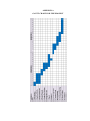
Gantt Chart for The Project
Programming Code for Mobile Robot
PAGE
46
47
CHAPTER 1
INTRODUCTION
1.1
Background
Autonomous mobile robots are built based on the application and human
need, for example to explore a new area or planet, to detect mines in an area and to
transfer goods from a point to another point. Each application needs the robot to still
alive until all of the tasks is done. Yet, most of these autonomous mobile robots
have limited operation time due to their power supplies and impossible to complete
its task especially if the application does a task repeatedly in long term.
The purpose of development in autonomous mobile robot is to eliminate
human intervention in most application. But, the limited time operation still need
human interferes to recharge its batteries. This result in a non-continuous robot task
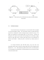
cycle as illustrated in Figure 1.1(a) and the main objective to eliminate human work
still not achieved. An addition research needs to be constructed to overcome this
problem.
2
Figure 1.1
Robot task cycle (a) with human intervention (b) without human
intervention.
1.2
Problem Statement
In an electronic factory, all components of a circuit module will be assembled
in a circuit board phase by phase. The circuit board is placed on a pallet and will be
passed from a checkpoint to another checkpoint using an automatic conveyor. The
pallet acts as platform for circuit module while it is on the conveyor. After the last
checkpoint, the complete circuit module will be packing in a box and ready to supply
while the empty pallet will be collected and transfer back to first checkpoint for
another circuit module. Usually the pallet is transferred by a human operator in
dozens.
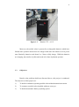
In Celestica Electronic (M) Sdn Bhd factory, they have their own
autonomous mobile robot to transfer the empty pallet back to first checkpoint named
Hitachi CFT – A.G.V. This autonomous guided vehicle (AGV) is not full automatic
as it needs human to load the pallets on it and the human also need to push run button
to move this mobile robot.
3
Figure 1.2
Hitachi CFT – A.G.V
Moreover, the mobile robot is powered by rechargeable batteries which have
limited time operation and need to be charged each time the batteries in low power
state. Basically, batteries need about 2 to 3 hour to fully charge. While the batteries
are charging, the transfer of pallet task needs to be done by human operator.
1.3
Objectives
Based on the problems had been discussed above, this project is conducted.
The objectives of this project are:
1)
To build a continuous operating mobile robot without human intervention.
2)
To construct a mobile robot installed with auto conveyor.
3)
To build an automatic battery replacing system
4
1.4
Scope of the Project
In order to make sure the results of this project are achieved, there are four
scopes had been outline and need to be constructed; mechanical, electronics,
software and field area.
1.4.1
Mechanicals
This project needs three assembly of mechanisms; mobile robot, charger dock
and battery box.
1)
The mobile robot is two wheeled drive mechanism, powered by two Seal
Lead Acid 12V batteries. Four infrared receiver sensors are attached to the
mobile robot and their function is to detect the location of charger dock.
2)
Charger dock, which is function as battery charger is the main part of this
project. On top of it will have a battery replacer mechanism and surround by
infrared transmitters to transmit infrared beam.
3)
Battery box consist of two SLA 12V batteries. The box can be attached and
detached from its socket.
5
1.4.2
Electronics
Six circuit boards are used in this project. There are 2 main boards for
mobile robot and charger dock, battery charger circuit, long range infrared
transmitter circuit, battery voltage monitor circuit and UIC00B – USB PIC
Programmer to load program to microcontroller.
Both main boards are using
microcontroller dsPIC30F4011 as the controller.
1.4.3
Softwares
The programming code is compiled using MPLab C Compiler and then the
hex file format will be loaded to the microcontroller using PICkit 2 software.
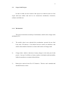
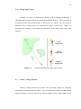
1.4.4
Field area
This project needs a 3.5 m x 6.5 m filed area to run. It is designed to
illustrate the situation in electronics’ factory. The area is illustrated in Figure 1.3
below. It will have two station; Station 1 and Station 2. Station 1 will be end point
of the conveyor, while Station 2 is the start point of the conveyor. So, mobile robot
will transfer empty pallet from Station 1 to Station 2. The charger dock will be
placed in center in between of Station 1 and Station 2. This design will make sure
the mobile robot will receive infrared beam while it is in line.
6
Figure 1.3
Field area for the project
CHAPTER 2
THEORY AND LITERATURE REVIEW
2.1
Introduction
Until now, many researches had been done on autonomous recharging mobile
robot. The important issues that need to be considered while design an autonomous
recharging mobile robot are the method for mobile robot to locate its dock place and
circuit to monitor battery voltage.
2.2
Locating the Dock Place
Locating is similar to the tracking technologies which is both of them used to
know where are the location of particular things.
According to O. Diegel, J.
Potgieter, and T. Cao (2005), in their paper, “Where’s Waldo? Low Cost RF Indoor
Tracking System”, some of the commonly available technologies that are suitable for
tracking networks include; infrared, radio frequency identification (RFID), Direct
Current (DC) electromagnetic and ultrasound. In addition, vision technique also one
8
of the most popular method and widely used for autonomous docking system. Each
of them has its own advantage and disadvantage.
2.2.1
Infrared as Location Detection
The benefits of using infrared are it’s consumes low power, low in cost and
compact in size. But infrared is limited by interference of ambient light and can be
disturb by other infrared devices. It is also bounded by line of range limitations. For
locating dock place, this method can be implementing by installing infrared
transmitter to the dock place while the passive infrared receiver can be attached at
the mobile robot. The mobile robot will acknowledge the dock location when the
passive IR receiver detected IR beam and after roaming around.
Figure 2.1
PICbot V
The best example of implementation of this method is the research conducted
by Chris and Dawn Schurs’ (2007) titled by “Docking Logic – Autonomously
Finding the Charging Base and Recharging”. Using small robot named PICbot V;
they implement infrared beam method to locate the dock place. Panasonic infrared
9
receiver (PNA4602) was attached to the robot to detect 38 kHz infrared beam
transmitted from the dock. A modification was made to the IR transmitter at the
dock, so that it can transmit IR beam in a long range. For their project, they limit the
IR beam to 10 ft. to make sure the signal is stable.
The weakness of this system, when it acknowledges the batteries is low, it
will move around until it detects the IR beam. What will happen if the batteries are
totally out of power before the mobile robot detects the IR beam?
(a)
Figure 2.2
(b)
Process of locating dock place (a) PICbot V moving around until
detect IR beam (b) then move forward to the dock.
2.2.2
Radio Frequency Identification Tag and Location Proximity
Differ with infrared; RF can pass through common material which is not limit
to line of sight range. Also, its range can reach till 30m compare to infrared which
its typical range is only about 5 m. RFID is a system which uses either passive radio
tags or active for the identification. The transmitter (called as the reader) will
transmits a low-power radio signal. The tag with specific identification (ID) receives
10
the signal and power up the integrated circuit (IC) on it. Then briefly, the IC will
converse with the transmitter for verification and exchanging data.
(a)
Figure 2.3
(b)
RFID Devices (a) RFID Passives Tag (b) RFID Reader
The distance of the tag can be approximately assumed by calculating its
speed propagation and time responses while the process of transmit and receive data.
O. Diegel, J. Potgieter, and T. Cao (2005), in the same paper, used same method in
locating its mobile robot.
Figure 2.4
Tracking system setup using RFID technologies
11
While the mobile robot followed the path, the RFID tag on it was detected by
the reader at the receiver nodes and the nearest receiver nodes will sent data to the
controlling computer using RS485 network.
The controlling computer will
acknowledge the ID of the reader module as well as the distance between the robot
and the reader. Note that the coordinate of the reader is fixed.
2.2.3
DC Electromagnetic
Besides, in high positioning systems, DC electromagnetic is commonly used.
Its signals are very sensitive to surrounding interference, even a metal can give a
signal if it in its area. As a result, high level filter is needed and the calibration needs
to be done precisely for the best output. Although its signal propagation is high, its
range limited to only 1 m to 3 m.
2.2.4
Low Cost Ultrasound
The last one is ultrasound, which is become more widely used in positioning
system. Its propagation speed is fixed to 343 m/s; make the length measurement
become more precise. Based on research conducted by L. Dazhai, F Hualei and W.
Wei (2008), titled by “Ultrasonic Based Autonomous Docking on Plane for Mobile
Robot”, the intensity of ultrasonic is influenced by the angles of the transmitter and
receiver.
12
(a)
Figure 2.5
(b)
Intensity character of Ultrasonic Sensor (a) Transmitter (b) Receiver
Small angle between transmitter and receiver gives high intensity. They used
this character of ultrasound as localization technique. Based on the characteristic the
angle between transmitter and receiver can be calculated using trigonometric
equation.
Figure 2.6
Position of Transmitter and Receiver Set
13
2.2.5
Vision Method for Localization System
Vision technology nowadays are widely use at autonomous robot.
By
interfacing the robot with the computer, the visual of environment of a robot can be
clearly monitored. As this method camera as its sensor, it is bounded with line of
sight limitation and it is limited to angle of the camera can view. Also, the robot
cannot get full review if there object obstruct its sight. But still we can adjust the
height of the camera to a little bit higher to get a better view.
An experiment, titled by “Visual Homing: Experimental Results on an
Autonomous Robot”, developed by P. Arena et al. (2007) apply visual system as the
main method to locate the position of the docking place. The camera was added with
spherical mirror (eye fish) to get 3600 view.
SPHERICAL
MIRROR
CAMERA
Figure 2.7
Figure 2.8
Position of camera and the spherical mirror
(a)
(b)
Spherical mirror (a) side view (b) bottom view (camera view)
14
2.2.6
Range Light Vision
Another research on autonomous docking and recharging technology is
“Docking and Charging System for Autonomous Mobile Robots”. This research was
developed in University of Brescia by C. Riccardo et al. (2005). They use range of
different color of light source to determine the angel of the dock.
Figure 2.9
illustrated the concept of determine the direction of the dock using range light
method.
Left of
Range Line
On the
Range Line
Right of
Range Line
Figure 2.9
2.3
Locating dock place by range light concept
Battery Voltage Monitor
Battery voltage monitor also be the most important systems in designing
autonomous recharging mobile robot. The microcontroller needs to acknowledge
when the batteries is in low state so that it have enough power to make a path to dock
15
place.
If the microcontroller did not get the signal of low battery power, the
autonomous recharge system cannot be preceded.
2.3.1
Using Quad Voltage Comparator
In a research conducted by E. Maningat et al. which is titled by “Random
Walk Application for Autonomous Vacuum Cleaner Robot”, they used quad voltage
comparator as a monitor to the voltage of 12V lead acid battery. Using 4 Light
Emitted Diodes (LED); which is each of them as indicator of 25% change in charge
condition of the battery. The battery is considered as fully charge if all of 4 LEDs
are light on.
Figure 2.10
Circuit diagram for 12v lead acid battery meter
16
2.3.2
LED Dot/Bar Display Using Chip LM3914
The heart of this circuit is IC LM3914, product of National Semiconductors.
The LM3914 can monitor voltage of a voltage supply then give output to LEDs in
dot or bar mode. This IC can support supply voltage in range of 3V to 25V, while
the intensity of LED’s brightness can be controlled using an external resistor. Refer
to Figure 2.11, resistor R4 is used to control the brightness of LEDs while resistor R1
and variable resistor R2 are used as voltage divider which is the variable resistor R2
can be tuned to set the minimum battery level.
Figure 2.11
Battery monitor circuit using LM3914
CHAPTER 3
METHODOLOGY
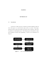
3.1
Introduction
In general, to conduct a project, it required a systematic planning to make the
flow of the project is in control and the output result is as expected. This chapter
discusses the flow of this project and how this project will be conducted. This can be
the guideline in conducting this project. Basically this project is divided into 3 major
part; mechanism, electronic and programming. The flow can be illustrated as in
Figure 3.1.
Figure 3.1
Flow of constructing this project
18
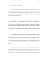
3.2
Overview of Overall System
This project consists of two parts; mobile robot and the dock place. The
overall system of these two parts can be divided into 5 main systems. The dock
place will be installed with 2 systems; charging system and battery replacer system,
while at the mobile robot will has 3 systems; locating the dock place, battery voltage
monitor system and line following.
First point of the mobile robot is at Station 2 (refer Figure 1.3) or the end of
the conveyor system. The mobile robot will wait there until its infrared sensor
detects the presence of empty pallet. Then it will do line following to the Station 1
(refer Figure 1.3) to unload empty pallet to Station 1 (start point of conveyor
system). After done unloading, the mobile robot will return to Station 1 and again,
wait for the presence of empty pallet, then load it to transfer to Station 1. The mobile
robot will do the task continuously until its battery reaches to minimum voltage
level.
When the batteries are in low power, the battery voltage monitor will send a
signal to microcontroller and the microcontroller will save the current task. The
signal from passive infrared receiver (locate at the base of the mobile) will be
processed and the microcontroller will made decision whether turn right or left until
the robot is facing to the dock place perpendicularly. After that, the robot will moves
forward until reach the dock place and touch the limit switch installed at the charger
dock.
At the charger dock, after receive signal from the limit switch, battery
replacer mechanism will align its arm so it is in line with battery box in mobile robot.
Then, it will clip and pull the battery box to go and load the battery box to the
charging station. After that, full charge battery (which is spare battery already store
19
on the storage station of charger dock) will be loaded to the mobile robot. The
mobile robot, afterwards, will return to its previous location to continue its task.
3.3
Mechanism Part
Mechanism in field of engineering can be defined as a system or structure of
moving parts that performs some function, especially in a machine. In other word,
mechanism in combination of joining that can perform a function. Mechanism need
actuator to make it moves in and sensor is used to give feedback on its movement.
This actuator and sensor allow user to control each movement of mechanism in
desired value by programming. Both mobile robot and charger dock have their own
design of mechanism and actuator.
3.3.1
Mobile Robot
Figure 3.2
Mobile robot’s CAD design
20
Figure 3.2 illustrate the drawing for the mobile robot. On top of the robot is
the auto conveyor part which is functioning as a platform to store the empty pallet
while the robot in transferring process. A DC motor is used as actuator to load
empty pallet into the auto conveyor. At the base part, a pair of DC motor is used to
navigate the robot while four passive infrared sensors are placed at the base of the
mobile robot.
The function of these IR sensors is to detect IR beam that has been
transmitted by the charger dock. As only IR sensor at right and front-right detect the
IR beam, the mobile will acknowledge the charger dock now is in its right hand side.
It will automatically turn to the right until both of front IR sensors detect the IR
beam. The function of the divider between both of front IR sensors is to make sure
the mobile robot is perpendicular to the charger dock.
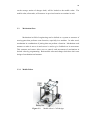
3.3.2
Dock Place
Figure 3.3
Charger dock’s CAD design
21
Figure 3.3 is the rough design for dock place. As the mobile robot comes
from any direction in range of 0 to 1800, the charger dock need to be design with
rotating mechanism so that it can still replace the battery even the robot comes from
any angle. The dock place also installed with slider so that it still can reach the
batteries at the mobile robot.
Charger dock consists of 4 parts; charging station, storage station, battery
replacer and IR beam transmitter. Charging station is used as station to charge low
power battery. There will be a socket for battery box and this socket is design to
make the battery replacing process become easier. Second part of this charger dock
is storage station. A full charge battery will be stored at this station until the mobile
robot come with the low power battery.
The main part of charger dock is battery replacer mechanism. It can move in
two degrees of freedom; rotating and sliding. End tool for battery replacer is locking
trigger which is function to lock the battery while in transferring process. The
rotating feature allows this mechanism to align its slider in line with the battery box
socket at mobile robot and charging station.
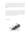
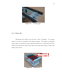
3.3.3
Battery Box
Figure 3.4
Battery box’s CAD design
22
Two SLA 12V batteries are placed together in a box, while each one of the
batteries terminal will be connected to the copper plate at the side of the box.
Negative terminal of each battery is connected to the each copper plate on the left
side of the box while positive terminal of the each battery is connected to the each
copper plate on the right side of box. The purpose of designing this battery box is to
make replacing battery process easier.
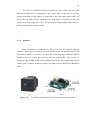
3.3.4
Actuators
Each movement of mechanism in this project will be actuated using an
actuator. Three types of actuators are used in this project; DC brushless motor, DC
brush motor and RC servo motor. A pair of DC brushless motor, model BLH Series
Brushless motor is used to drive the two wheeled mobile robot. This model is a
dedicated high-strength gearhead for brushless motors that also supports high-speed
rotation and a compact board-type driver is needed to drive BLH Series Brushless
motor.
(a)
Figure 3.5
(b)
(a) BLH series brushless motor (b) compact board-type driver
23
Table 3.1: Specification of BLH series brushless motor
Item
Specification
Motor Size
50W (1/15 HP)
Gear Ratio
5:1
Speed Range
20 – 600 rpm
Power Supply
24 VDC
Rated Torque
7.9 lb-in / 0.9 Nm
Besides DC brushless motor, DC brush motors are widely used in this project
such as, DC geared motor, power window motor and DC motor. On mobile robot,
power window motor is used to load and unload pallet while on charger dock, it is
used to rotate the arm of battery replacer mechanism.
Figure 3.6
Power window motor
Table 3.2: Specification for Power Window Motor
Item
Specification
Voltage Rating
12 VDC
Speed (No Load)
85 rpm
Current (No Load)
3A
Current (Load)
7A
Current (Lock)
20 A
Torque
30 kg cm
24
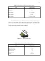
Another DC brush motor that is used is DC geared motor, model SPG30-30.
This motor is used for sliding part of battery replacer mechanism. This motor is
suitable for light use such as bank note machine, handling machine and to drive light
mobile robot.
Figure 3.7
SPG30-30 DC geared motor
Table 3.3: Specification for SPG30-30 DC Geared Motor
Item
Specification
Voltage Rating
12 VDC
Output Power
1.1 Watt
Rated Speed
103 rpm
Rated Current
410 mA
Rated Torque
127.4 mN m
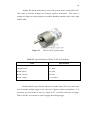
Beside both DC geared motor and power window motor, RC servo motor also
used to actuate locking trigger at the end tool of battery replacer mechanism. It is
necessary for the actuator to move by angel of 900 to control each time of trigger.
That is why RC servo motor is used to trigger the locking trigger.
25
Figure 3.8
RC servo motor
Table 3.4: Specification of RC servo motor
Item
Voltage Rating
Specification
6 VDC
Speed
0.12 s / 600
Torque
2.70 kg cm
Size
(29 x 11.7 x 30.2) mm
Weight
3.3.5
16 g
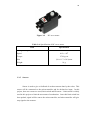
Sensors
Sensor is used to give a feedback of each movement done by the robot. This
sensor will be connected to the microcontroller and be declared as input. In this
project, there two sensor are used; limit switch and IR sensor. Limit switch is widely
used in this project to limit the movement of mechanism. Once this limit switch has
been pushed, signal will be sent to the microcontroller, and microcontroller will give
stop signal to the actuator.
26
Figure 3.9
Limit switch
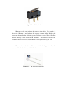
IR sensor can be used to detect the presence of an object. For example, in
this project, IR sensor is used to detect the presence of empty pallet. Besides, this
sensor can also use for line following system. Different colour of floor will reflect
different intensity of light emitted by IR transmitter. This situation will varied the
resistance value of IR receiver sensor when it receives light reflect by the floor.
IR sensor also used to detect IR beam transmit by the charger dock. Four IR
sensors will be placed at the base of mobile robot.
Figure 3.10
IR sensor and transmitter
27
3.4
Electronics
As mentions in Chapter 2, there are six circuit boards are used in this whole
project. Two of them, main board circuit for mobile robot and battery voltage
monitor circuit, are used for the system at the mobile robot, while three circuits are
used for operation in charger dock. The circuits are main board circuit, battery
charger circuit and long range IR transmitter circuit.
Both of main board, for mobile robot and charger dock, use microcontroller
from Microchip which is dsPIC30F4011.
To program those to microcontroller,
UIC00B – USB PIC Programmer circuit will be used. This programmer is suitable
to program most of PIC family from Microchip.
3.4.1
Power Supply Unit
Power supply is like the soul for the robot. Without power supply, a robot
cannot function. As the mobile robot need to move free, whole system in mobile
robot will be powered by two units of Seal Lead Acid 12V battery. This SLA 12V
battery can reach up to 14.46 V in full charge mode (first time used). The advantage
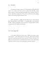
of using SLA battery is it is low cost, robust and low maintenance required.
28
Figure 3.11
SLA 12V battery
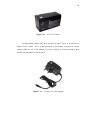
In other hand, charger dock does not need to move freely as it needs to be
placed fix at a place. So, it is not necessary to use battery to power its circuit.
Charger dock use AC to DC adapter as it power supply, so it has no problem with
limited time operation as mobile robot.
Figure 3.12
12 VDC AC to DC adapter
29
3.4.2
Main board Circuits
Main board circuit is the interfaces circuit for microcontroller that used to
control all activities in the system. The design of the circuit is depended on how
many inputs and outputs of the microcontroller and what are the inputs and outputs
that been used.
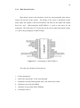
Microcontroller dsPIC30F4011 is used as the brain for the
mainboard. This chip offers 27 I/O pins that can be used as input and outputs. Figure
3.13 shows the pin diagram of dsPIC30F4011.
Figure 3.13
Pin diagram of dsPIC30F4011
The other specifications of this chip are:
1. 83 base instructions
2. 24-bit wide instructions, 16-bit wide data path
3. 48 kilobytes on-chip flash program space (16k instruction words)
4. 2 kilobytes of on-chip data RAM
5. 1 kilobyte of nonvolatile data EEPROM
6. 30 interrupt sources:
30
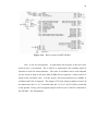
This microcontroller needs supply voltage of 5V to operate. For this reason,
a 5V voltage regulator circuit is needed to regulate 12V voltage from battery to
output of 5V. The main component to produce 5V of voltage is LM7805 chip
(Figure 3.14). This chip can support input voltage in range of 7V to 28V. Figure
below illustrated the circuit diagram for voltage regulator circuit.
Figure 3.14
Figure 3.15
LM7805 chip
Voltage regulator circuit
With supply voltage of 5V, the basic circuit for microcontroller can be done.
This basic circuit is needed to enable the microcontroller. Some pin need to be
interface with other component to activate it function. Figure 3.16 below shows
basic circuit for microcontroller to operate.
31
Figure 3.16
Basic circuit for dsPIC30F4011
Pin 1 is pin for reset purpose. A push button can be place to the pin if user
needs to have a reset button. Pin 13 and 14 is connected to the oscillator which is
function as clock for microcontroller. The value of oscillator can be varied depend
on user needs as long as not more than 40 MHz but its capacitor’s value need to be
based on the oscillator value. For this project, this microcontroller use 10MHz of
oscillator and 33pF of capacitor. The output of 5V from voltage regulator circuit will
be connected to pin 11, 21, 32 and 40 while pin 12, 20, 31 and 39 will be connected
to the ground. Lastly, pin for program purpose which is pin 25 and 26; connected to
the UIC00B – PIC Programmer.
32
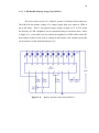
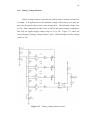
3.4.3
Battery Voltage Monitor
Battery voltage monitor is placed at the mobile robot to monitor current level
of voltage. It is important to set the minimum voltage of the battery as to spare the
power for the mobile robot to move to the charger dock. The minimum voltage is set
to 12V. Main component for this circuit is LM324 chip (quad voltage comparator).
This chip can support supply voltage range of 3V to 30V. Figure 3.17 shows the
circuit diagram for battery voltage monitor circuit. LED4 will light on if the voltage
reaches to 12V.
Figure 3.17
Battery voltage monitor circuit
33
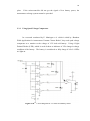
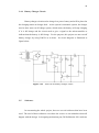
3.4.4
Battery Charger Circuit
Battery charger circuit used to charge low power battery and will be placed at
the charging station at charger dock. As the system is automatic system, the charger
need to have auto cut-off charge system, which mean, the battery will stop charging
if it is full charge and the circuit need to give a signal to the microcontroller to
indicate that the battery is full charge. For the purpose, this project use auto cut-off
battery charger by using LM338 as its heart. Its circuit diagram is illustrated as
figure below.
Figure 3.18
3.5
Auto cut-off battery charger circuit
Softwares
In constructing the whole project, there are several softwares that have been
used. The used of these softwares can reduce the cost as we can stimulate what will
happen with the design. In designing mechanism part, DS Solidworks 2010 software
34
is being used. DS Solidworks is a mechanical design which make easier in designing
or sketching out ideas. Using easy understanding features, it is suitable for beginners
of designer to try to learn using software in sketching.
Figure 3.19
DS Solidworks
MPLab IDE compiler is used to compile the programming code while PICkit
2 software is used when the compiled code need to be loaded to the microcontroller.
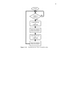
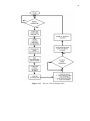
When writing the programming code, it is advised to design flow chart of overall
process. This flow chart will make programming part become easier. Figure 3.21,
3.22 and 3.23 illustrate flow chart of overall process for this project.
Figure 3.20
MPLab IDE C Compiler
35
NO
YES
Figure 3.21
Normal process’ flow of mobile robot
36
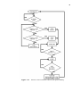
NO
YES
YES
NO
YES
NO
NO
YES
NO
YES
Figure 3.22
Process’ flow of mobile robot in low power battery
37
NO
YES
YES
NO
Figure 3.23
Process’ flow at charger dock
CHAPTER 4
RESULT AND DISCUSSION
4.1
Hardware
Based on the problem statement and three main objectives discussed in
Chapter 1, two mechanisms had been constructed. There are mobile robot and
charger dock.
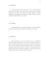
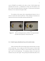
4.1.1
Mobile Robot
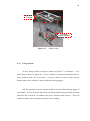
The mobile robot is use to transfer pallet from one station to another station.
This mobile robot is drive by two DC brushless motor (BLH Series Brushless motor)
with 4 pair of IR sensor circuit as a sensor to guide this robot to move by following
the line. Four IR receivers were put at the base robot for detecting the charger dock.
Figure 4.1 shows the isometric view of the actual form of mobile robot.
39
PALLET
LIFTER
BATTERY
BOX’S SOCKET
Figure 4.1
4.1.2
Mobile robot
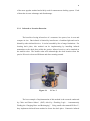
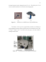
Charger Dock
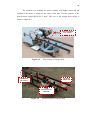
At first, charger dock is design as shown in Figure 3.3 in Chapter 3. The
actual form is shown in Figure 4.2. It uses 3 motors to actuate all mechanism part; 2
power windows and 1 RC servo motor. A power window is used to rotate the arm
and the other power window is used to slide the locking trigger.
But, the position of power window which is used to slide locking trigger is
not suitable. It is locate at the end of the arm which produces large amount of inertia
when the arm is rotated. In addition, the power window itself is heavy. This will
result the charger dock not stable when the arm is rotating.
40
The solution is to exchange the power window with lighter motor and the
position of the motor is change to the center of the arm. For this purpose, a DC
geared motor; model SPG30-30 is used. The new of the charger dock design is
shown is Figure 4.3.
NOT SUITABLE
LOCATION
Figure 4.2
First version of charger dock
LOCKING
TRIGGER
CHARGING
STATION
NEW
LOCATION OF
MOTOR
Figure 4.3
Second version of charger dock
41
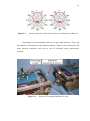
Figure 4.4
4.1.3
Locking trigger
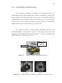
Battery Box
This battery box (Figure 4.4) can store 2 SLA 12V Battery. Two copper
plates at its side are connected to the battery terminal. The purpose of using this
copper plate is to make the process attach and detach to its socket become easier,
which is the battery box only need to slide to the limit of the socket to connect the
battery to the circuit.
COPPER PLATES
Figure 4.5
Battery box
CHAPTER 5
CONCLUSION AND RECOMMENDATION
5.1
Conclusion
For the conclusion, there 3 main parts that have been construct in this project;
mechanism, electronic and programming. In mechanism part, there are 3 products
which is mobile robot, charger dock and battery box. Practically, this project is
suitable for pallet lifting application that transfer pallet from one station to another.
The mechanism at the mobile robot has auto detect pallet feature which is it will wait
for pallet presence. Using this system will eliminate human work to change the
mobile robot battery and time of maintenance can be reduced; instead go and charge,
it is better to go and replace its battery which is it can the time.
5.2
Recommendation
For future plan, it is advisable to upgrade some part of this project such as
listed below:
43
1.
To add power saver mode which is can extend battery life. This feature can
be upgrade by upgrading in circuit part.
2.
Enhancing communication system between mobile robot and charger dock as
infrared beam can be blocked by an obstacle.
REFERENCES
C. Riccardo, T. Fabio, B. Paolo and F. Roberto. Docking and Charging System for
Autonomous Mobile Robots. University of Brescia; 2005.
Cytron Technologies. USB ICSP PIC Programmer User’s Manual V1.0. Malaysia:
Product User’s Manual. December 2011.
E. Maningat, B. Monterola, E. Obrero, R. Samante, and J. Villafuerte. Random Walk
Application for Autonomous Vacuum Cleaner Robot. Ateneo de Naga
University.
http://img.diytrade.com/cdimg/950543/9661382/0/1247100999/DC_Motor_Suitable
_for_Toys_and_Garden_Tools.jpg as viewed on June 2012
http://www.cytron.com.my/viewProduct.php?pcode=HD1160A&name=RC%20Micro%20Servo%20Motor as viewed on May 2012
http://www.cytron.com.my/viewProduct.php?pcode=MO-PW-R as viewed on May
2012
http://www.engineersedge.com/motors/brushless_dc_motor.htm as viewed on June
2012
http://www.gadgetfolder.com/super-efficient-rfid-tag-reader-from-mitsubishi.html as
viewed on November 2011
http://www.industrysearch.com.au/Products/Handheld-RFID-Reader-Intermec-IP3064353 as viewed on November 2011
http://www.interinar.com/vexta-pk244-02ba-c5.html as viewed on June 2012
45
http://www.orientalmotor.com/products/brushless-motors/blh-series.html as viewed
on June 2012
http://www.schursastrophotography.com/robotics/dockinglogic.html as viewed on
November 2011
L. Dazhai, F Hualei, and W. Wei. Ultrasonic Based Autonomous Docking on Plane
for Mobile Robot. Proceeding of the IEEE International Conference on
Automation and Logistics. September, 2008. Qingdao, China: IEEE, 2008.
1396-1401.
M. C. Silverman, B. Jung, D. Nies and G. S. Sukhatme. Staying Alive Longer:
Autonomous Robot Recharging Put to the Test. University of Southern
California; 2003.
Microchip Technology Inc. dsPIC30F Family Reference Manual. U.S.A: Datasheet.
2003.
National Semiconductor Corporation. LM138/LM338 5-Amp Adjustable Regulators.
Product Specification. May 1998
O. Diegel, J. Potgieter, and T. Cao. Where Waldo? Low Cost RF Indoor Tracking
Systems. 1st International Conference on Sensing Technology. November 2123, 2005. Palmerston North, New Zealand: 2005. 48-53.
P. Arena, S. De Fiore, L. Fortuna, L. Nicolosi, L Patan´ e, and G. Vagliasindi. Visual
Homing: Experimental Results on an Autonomous Robot. IEEE 2007. 2007.
Catania, Italy: IEEE. 2007. 304-307.
Philips Semiconductors. Low Power Quad Op Amps. Product Specification.
November 1995.
APPENDIX A
GANTT CHART FOR THE PROJECT
47
APPENDIX B
PROGRAMMING CODE FOR MOBILE ROBOT
#include <p30f4011.h>
_FOSC(CSW_FSCM_OFF & XT_PLL8);
_FBORPOR(MCLR_EN & PWRT_OFF);
//Define Input & Output
#definebutton1
_RD1
#definebutton2
_RD3
#defineled1
_LATC13
#defineled2
_LATC14
#defineled3
_LATE8
#define Rccw
_LATB0
#define Rrun
_LATB1
#define Rspeed
PDC1
#define Lccw
_LATB2
#define Lrun
_LATB3
#define Lspeed
PDC2
#define pwindow1
_LATB4
#define pwindow2
_LATB5
#define pw_speed
PDC3
#define z_1
_RE5
#define s0_1
_LATF0
#define s1_1
_LATF1
#define s2_1
_LATF4
#define z_2
_RF5
#define s0_2
_LATF6
#define s1_2
_LATD0
48
#define s2_2
_LATD2
//Define Pin for Multiplexer
#defineIRdock_L
mux_1(0)
#defineIRdock_R
mux_1(1)
#defineIRdock_FL
mux_1(2)
#defineIRdock_RL
mux_1(3)
#definesensor0
mux_1(4)
#definesensor1
mux_1(5)
#definesensor2
mux_1(6)
#definesensor3
mux_1(7)
#definebattery
mux_2(2)
#definepallet
mux_2(5)
#defineunload
mux_2(1)
#defineload
mux_2(6)
#definel_dock
mux_2(0)
#definer_dock
mux_2(7)
#define batterydock
mux_2(3)
//Global Variable
unsigned char mode;
unsigned char memLine;
unsigned char junction;
unsigned short mux;
unsigned char mux_1(unsigned char w);
unsigned char mux_2(unsigned char w);
//Funtion Prototype
void stop (void);
void turn (void);
49
void forward (void);
void reverse (void);
void turn_180 (void);
void turn_left (void);
void turn_right (void);
void pw_stop (void);
void pw_forward (void);
void pw_reverse (void);
void un_loadPallet (void);
void line_following (void);
void delay (unsigned long i);
void execute (unsigned char task);
void indicator (unsigned char show);
void count_junction (unsigned char bil);
void __attribute__((__interrupt__,auto_psv)) _OscillatorFail(void)
{
while(1){;}
}
void __attribute__((__interrupt__,auto_psv)) _AddressError(void)
{
while(1){;}
}
void __attribute__((__interrupt__,auto_psv)) _StackError(void)
{
while(1){;}
}
void __attribute__((__interrupt__,auto_psv)) _MathError(void)
{
while(1){;}
}
void __attribute__((__interrupt__,auto_psv)) _T3Interrupt(void)
{
_T3IF = 0;
//clear flags
if (battery == 1)
{
if (IRdock_R == 1 && IRdock_L == 0)
{
memLine = 1;
while (IRdock_L == 0 || IRdock_R == 0)
50
{
turn_right();
}
while ( (l_dock == 0) || (r_dock == 0) )
{
forward();
}
stop();
delay(850);
}
else if (IRdock_R == 0 && IRdock_L == 1)
{
memLine = 2;
while (IRdock_L == 0 || IRdock_R == 0)
{
turn_left();
}
while ( (l_dock == 0) || (r_dock == 0) )
{
forward();
}
stop();
delay(850);
}
while (batterydock == 0){;}
reverse ();
delay (10000);
turn_left();
51
delay(2700000);
while( (sensor0 == 1) || (sensor3 == 1) )
{
forward();
}
}
}
//Initialization for Microcontroller
void init(void)
{
ADPCFG = 0xfffe;
//define input output for pin
TRISB =0x0000;
TRISC =0x0000;
TRISD =0x000a;
TRISE =0x0020;
TRISF =0x0020;
OC1CON = 0x0000; //close all OCxCON
OC2CON = 0x0000;
OC3CON = 0x0000;
OC4CON = 0x0000;
IC1CON = 0x0000;
//close all ICxCON
IC2CON = 0x0000;
IC7CON = 0x0000;
IC8CON = 0x0000;
PTCONbits.PTEN=1;
PWMCON1 = 0x0F03;
PTCON = 0x2003;
//1:1 prescale and postscale, up/down double
updates
PTMR = 0x0000;
PTPER = 511;
//10-bit resolution, 29.296875KHz PWM
52
SEVTCMP = 0x0000;
PWMCON2 = 0x0004;
//immediate PDC updates
FLTACON = 0x0000; //disable Fault A control
OVDCON = 0xff00; //disable override control
PDC1 = PDC2 = 0;
//initial duty cycle equals zero, 1024 equals 100%
T3CON=0x2010;
//set Timer 3 synchronize with internal clock,
1:8 prescale
PR3=375;
//interrupt every 0.1ms (formula =
2ms/((1/30M)x 64) )
TMR3=0;
SRbits.IPL
= 7;
// disable all user's interrupt
INTCON1
= 0x0000;
INTCON2
= 0x0000;
IFS0 = 0x0000;
IFS1 = 0x0000;
IFS2 = 0x0000;
SRbits.IPL
= 0;
// clear all interrupt flag
// disable all user's interrupt
_T3IE = 1;
//enable Timer 3 interrupt
_T3IP = 4;
//T3 low pirority
U2STAbits.UTXEN =1;
//enable transmit
}
//Main Program
int main()
{
init();
T3CONbits.TON=1;
mode = 0;
53
indicator(0);
while(1)
{
while (pallet == 1){;}
//no pallet in front
un_loadPallet();
turn_180();
count_junction (1);
turn_left();
count_junction(1);
turn_left();
forward();
delay(100000);
un_loadPallet();
turn_180();
count_junction (1);
turn_right();
count_junction(1);
turn_right();
forward();
delay(100000);
}
}
void delay (unsigned long i)
{
for (
; i>0 ; i--
);
}
//
INDICATOR & SWITCH MODE
void indicator (unsigned char show)
{
switch(show)
54
{
case 0 :led1=1; led2=1; led3=1; break;
case 1 :led1=1; led2=1; led3=0; break;
case 2 :led1=1; led2=0; led3=1; break;
case 3 :led1=1; led2=0; led3=0; break;
case 4 :led1=0; led2=1; led3=1; break;
case 5 :led1=0; led2=1; led3=0; break;
case 6 :led1=0; led2=0; led3=1; break;
case 7 :led1=0; led2=0; led3=0; break;
}
}
void execute (unsigned char task)
{
switch(task)
{
case 0 :led1=1; led2=1; led3=1; delay(2727272/2);
led1=0; led2=0; led3=0; delay(2727272/2);
break;
case 1 :led1=1; led2=1; led3=0; delay(2727272/2);
led1=1; led2=1; led3=1; delay(2727272/2);
break;
case 2 :led1=1; led2=0; led3=1; delay(2727272/2);
led1=1; led2=1; led3=1; delay(2727272/2);
break;
case 3 :led1=1; led2=0; led3=0; delay(2727272/2);
led1=1; led2=1; led3=1; delay(2727272/2);
break;
case 4 :led1=0; led2=1; led3=1; delay(2727272/2);
led1=1; led2=1; led3=1; delay(2727272/2);
break;
55
case 5 :led1=0; led2=1; led3=0; delay(2727272/2);
led1=1; led2=1; led3=1; delay(2727272/2);
break;
case 6 :led1=0; led2=0; led3=1; delay(2727272/2);
led1=1; led2=1; led3=1; delay(2727272/2);
break;
case 7 :led1=0; led2=0; led3=0; break;
}
}
//
POWER WINDOW
void un_loadPallet (void)
{
while (unload == 1)
{
pw_forward();
}
pw_stop();
delay(850);
while (load == 1)
{
pw_reverse();
}
pw_stop();
delay(850);
}
void pw_forward (void)
{
pwindow1 = 1;
56
pwindow2 = 0;
}
void pw_reverse (void)
{
pwindow1 = 0;
pwindow2 = 1;
}
void pw_stop (void)
{
pwindow1 = 0;
pwindow2 = 0;
}
//
VEXTA
void forward (void)
{
Lrun=Rrun=0;
Lccw=0;
Rccw=1;
}
void stop (void)
{
Lrun=Rrun=1;
Lspeed=Rspeed=0;
delay(10000);
}
void reverse (void)
{
Lrun=Rrun=0;
57
Lccw=1;
Rccw=0;
}
void count_junction (unsigned char bil)
{
junction = 0;
while (junction < bil)
{
line_following();
if( !sensor0 && !sensor3 )
{
junction++;
}
}
}
void turn_right(void)
{
Lrun = Rrun = 0;
Lccw = 1;
Rccw = 1;
Lspeed = Rspeed = 100;
}
void turn_left(void)
{
Lrun = Rrun = 0;
Lccw = 0;
Rccw = 0;
Lspeed = Rspeed = 100;
}
void turn_180 (void)
58
{
while ( !sensor0 || !sensor1 || !sensor2 || !sensor3 )
{
turn_right();
}
stop();
delay(850);
while ( (sensor1 == 1) || (sensor2 == 1))
{
turn_right();
}
stop();
delay(850);
}
//
LINE FOLLOWING
void line_following (void)
{
unsigned char position = 0b0000;
if(sensor0 == 0)
{ position += 0b1000; }
else if(sensor1 == 0) { position += 0b0100; }
else if(sensor2 == 0) { position += 0b0010; }
else if(sensor3 == 0) { position += 0b0001; }
switch(position)
{
case 0b1000
:
forward();
memLine = 1;
Rspeed = 100;
59
Lspeed = 150;
break;
case 0b0100
:
forward();
memLine=1;
Rspeed = 100;
Lspeed = 150;
break;
case 0b1100
:
forward();
memLine = 1;
Rspeed = 100;
Lspeed = 150;
break;
case 0b0110
:
forward();
Rspeed = 150;
Lspeed = 150;
break;
case 0b0011
:
forward();
memLine = 2;
Rspeed = 150;
Lspeed = 100;
break;
case 0b0010
:
forward();
memLine = 2;
Rspeed = 150;
Lspeed = 100;
break;
case 0b0001
:
forward();
60
memLine = 2;
Rspeed = 150;
Lspeed = 100;
break;
case 0b0000 : if(memLine == 1)
{
delay(100000);
while(sensor3 == 0)
{
turn_left();
}
stop();
}
else if(memLine == 2)
{
stop();
delay(100000);
while(sensor0 == 0)
{
turn_right();
}
stop();
}
break;
default
:
forward();
Rspeed = 150;
Lspeed = 150;
break;
61
}
}
//
MULTIPLEXER
unsigned char mux_1(unsigned char w)
{
s0_1 = (w&0b0001)?1:0;
s1_1 = (w&0b0010)?1:0;
s2_1 = (w&0b0100)?1:0;
delay(100);
if(z_1==0) {return 0;}
else if(z_1==1) {return 1;}
}
unsigned char mux_2(unsigned char a)
{
s0_2 = (a&0b0001)?1:0;
s1_2 = (a&0b0010)?1:0;
s2_2 = (a&0b0100)?1:0;
delay(100);
if(z_2==0) {return 0;}
else if(z_2==1) {return 1;}
}