1
Digital Photogrammetric System
Version 5.21
USER
MANUAL
Aerial Triangulation
1. Aerial triangulation data ...................................................................................................... 3
2. Workflow ............................................................................................................................... 4
2.1 Control of stages performing............................................................................................ 5
3. Interior orientation ............................................................................................................... 6
3.1 Interior orientation menu ..................................................................................................6
3.2 Cameras management..................................................................................................... 7
3.2.1 Input and editing of film camera parameters............................................................. 9
3.2.2 Input of digital camera parameters.......................................................................... 11
3.2.3 Cameras parameters import and export ................................................................. 16
3.3 Interior orientation of film camera images ...................................................................... 17
3.3.1 Manual measuring of fiducial marks........................................................................ 18
3.3.2 Semiautomatic interior orientation........................................................................... 20
3.3.3 Automatic interior orientation .................................................................................. 23
3.4 Interior orientation of digital camera images .................................................................. 25
3.5 Report on interior orientation.......................................................................................... 25
4. Relative orientation and ground control points measurement ..................................... 30
4.1 Orientation menu............................................................................................................ 32
4.2 Input and measuring of ground control points................................................................ 34
4.2.1 GCP input................................................................................................................34
4.2.1.1 Import of GCP list .............................................................................................................. 36
4.2.1.1 Export of GCP list .............................................................................................................. 39
4.2.2 GCP measurement.................................................................................................. 40
4.2.3 Measuring control point on map.............................................................................. 42
4.2.3.1 Preparation and loading of georeferenced data .................................................................. 42
4.2.3.2 Searching corresponding GCPs on images......................................................................... 43
4.2.3.3 Adding to list and measuring GCP on project images........................................................ 44
4.2.3.4 Map window....................................................................................................................... 47
4.2.3.5 Raster map georeference .................................................................................................... 49
4.3 Automatic tie points measurement................................................................................. 51
4.3.1 Working order and terms......................................................................................... 52
4.3.2 Performing of automatic tie points measurement ................................................... 52
4.3.2.1 Automatic tie point measurement window ......................................................................... 53
4.3.2.2 Additional measurement parameters .................................................................................. 56
4.4 Manual measuring of triangulation points ...................................................................... 62
4.4.1 Points measurement module ................................................................................ 62
4.4.1.1 Main window of Points measurement module................................................................. 65
4.4.1.1.1 Windows of opened images ......................................................................................... 70
4.4.1.2 Triangulation points window.............................................................................................. 72
4.4.1.3 Parameters of points measurement ..................................................................................... 76
4.4.1.4 Analysis of autocorrelation coefficient .............................................................................. 77
4.4.1.5 Measuring correspondent point search area ....................................................................... 77
4.4.2 Points measurement workflow ................................................................................ 78
4.4.2.1 Points measurement on a strip stereopair ........................................................................... 78
4.4.2.1.1 Measuring new points ................................................................................................. 78
4.4.2.1.2 Transferring existing points ........................................................................................ 78
4.4.2.2 Points measurement on a stereopair between strips ........................................................... 78
4.4.2.3 Points measurement in triplets............................................................................................ 78
4.4.2.4 Working in 4 windows ....................................................................................................... 78
4.4.2.5 Working in 6 windows ....................................................................................................... 79
4.4.3 Points measurement in stereomode ....................................................................... 79
4.4.4 Displaying points ..................................................................................................... 82
4.4.4.1 Point symbols ..................................................................................................................... 82
4.4.4.2 Point filter........................................................................................................................... 83
4.4.4.3 Displaying points in 2D window........................................................................................ 84
4.4.5 Point measurements deletion.................................................................................. 87
Aerial triangulation
2011
4.4.5.1 Import of flight line file...................................................................................................... 89
4.4.6 Triangulation points import...................................................................................... 91
4.4.6.1 Import from PAT-B............................................................................................................ 91
4.4.6.1.1 Format of file of geodetic point’s coordinates ............................................................ 92
4.4.6.1.2 Format of file of points measurements on images....................................................... 93
4.4.6.2 Import from X-Points ......................................................................................................... 94
4.4.6.3 Triangulation points import from PHOTOMOD 4.x XPT ................................................. 95
4.4.7 Triangulation points export...................................................................................... 95
4.4.7.1 Export to PAT-B ................................................................................................................ 95
4.4.7.2 Export to X-Points.............................................................................................................. 96
4.5 Relative orientation accuracy control ............................................................................. 96
4.5.1 Relative orientation report settings.......................................................................... 96
4.5.2 Relative orientation report ....................................................................................... 99
4.5.2.1 Report for selected stereopair........................................................................................... 102
4.5.2.2 Report for selected triplet ................................................................................................. 105
5. Import of exterior orientation data .................................................................................107
5.1 Import exterior orientation data window .......................................................................107
5.1.1 Format of PAT-B file..............................................................................................111
5.2 Import from UltraCam metadata...................................................................................112
5.3 Exterior orientation data list..........................................................................................113
5.4 Accuracy control of imported data................................................................................115
6. Block layout ......................................................................................................................116
6.1 Data for block layout creation.......................................................................................116
6.2 Block layout creation ....................................................................................................117
6.3 Using DEM data for block layout creation....................................................................121
6.4 Manual matching of images .........................................................................................122
7. Project types .....................................................................................................................123
7.1 Number of GCP recommended for relative orientation of space images ....................124
1. Aerial triangulation data
After project creation and block forming (when project images are loaded and adjusted) you
can proceed to data collection for creating of strip or block aerial triangulation networks.
Once all necessary initial data is collected, you can perform block adjustment (see Block
adjustment User Guide). The result of images block creation and adjustment is
determination of images exterior orientation parameters, which are used for further
photogrammetric processing (see Project processing User Guide).
Use the following data to perform aerial triangulation:
interior orientation parameters – determine location and orientation of image
coordinate system in relation to digital image coordinate system. Images interior
orientation is obligatory stage.
Relative orientation parameters – results of triangulation points measurements on
images of a block.
Results of ground control points measurement on images of a block (see also the
chapter Input and measuring of ground control points).
Exterior orientation parameters, measured by GPS/IMU on-board systems. Exterior
orientation parameters are coordinates of projection centers and 3 angles that
together determine real images location in space. If you have exterior orientation
parameters you can import them (see the chapter Import of exterior orientation
parameters). In case of satisfying accuracy of imported exterior orientation
3
RACURS Co., Ul. Yaroslavskaya, 13-A, office 15, 129366, Moscow, Russia
PHOTOMOD 5.21
parameters, proceed immediately to processing stage – stereovectorization, DEM
building, orthomosaic creation (see Project processing User Guide). Otherwise, you
should define more exactly images location in space using tie points (i.e. perform
Relative orientation), as well as using ground control points.
2. Workflow
If the on-board exterior orientation data is unavailable, the task of data collection for block
adjustment turns into aerial triangulation, which includes:
© 2011
4
Aerial triangulation
2011
input and measuring of ground control points
images relative orientation
measuring of tie points on stereopairs and in triplets;
measuring of inter-strip tie points.
After executing of each stage of data collection for aerial triangulation you should perform
control of measurements accuracy and errors elimination. See the chapter Control of stages
performing.
2.1 Control of stages performing
You can control data collection for exterior orientation (block adjustment) using the following
features:
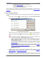
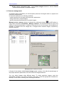
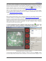
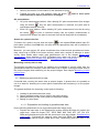
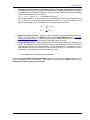
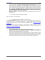
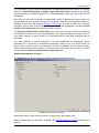
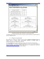
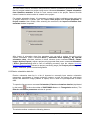
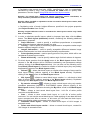
Project state summary window, opened using menu command Project | Project
state or using the button
of main PHOTOMOD Core toolbar.
Project state summary window
Project state summary allows viewing project state as a whole. Completed project
stages are marked by symbol
, partly accomplished –
, unperformed stages –
.
Tools for opening of different dialogue window used for project processing are
provided for each project stage. The Project state window shows:
– state of block forming stage (number of strips and images) and tools for
adding of images and strips to a project. See the chapter Block forming in
Project creation User Guide;
– state of interior orientation stage and tools for specifying of project cameras,
interior orientation executing and viewing of resulting report. See the chapter
Interior orientation;
– state of relative orientation stage and tools for block layout creation, relative
orientation executing and viewing of resulting report. See the chapter Relative
orientation and ground control points measurement;
– state of exterior orientation stage and tool for block adjustment. See Block
adjustment User Guide.
5
Detailed reports on interior and relative orientation to check results of aerial
triangulation and control of measurements accuracy. (See the chapters Report on
interior orientation and Relative orientation report).
Block layout – to implement visual control using block scheme that is created
considering existed data or data collected during project processing: overlap areas
RACURS Co., Ul. Yaroslavskaya, 13-A, office 15, 129366, Moscow, Russia
PHOTOMOD 5.21
sizes, manual or automatic feature matching data, imported exterior orientation
parameters, tie and GC points measurements, etc. See the chapter Block layout.
3. Interior orientation
The interior orientation procedure is used to find the position and the orientation of film
coordinate system relatively to coordinate system of digital image. Besides, during interior
orientation the parameters describing a systematic film distortion can be found.
The parameters defined in the process of interior orientation are used to transform measured
image point coordinates from digital image coordinate system to film coordinate system.
Three types of transformation from digital image coordinate system to film coordinate system
can be performed during interior orientation. You can apply one of them depending on
camera data entered to passport.
If during camera calibration fiducial marks data were measured in camera coordinate system
(calibration parameters – Fiducial coordinates), you can apply affine or projective
transformations to measured point coordinates, to transform the point coordinates from
digital image coordinate system to film coordinate system and correct systematic errors.
Please note, that you should measure at least 3 fiducial marks on image to find affine
transformation parameters, and at least 4 fiducial marks to find projective transformation
parameters.
If you have measured less than 3 marks (if the rest are invisible, for instance), you can use
simple transformation Rotation, scale, shift.
3.1 Interior orientation menu
To perform interior orientation use menu command Orientation | Interior orientation that
includes the following commands:
Report on interior orientation – opens report with interior orientation data (duplicated
by the
button). See the chapter Report on interior orientation.
Manual interior orientation – opens Interior orientation dialogue used for manual
).
measuring of fiducial marks if case of film camera (duplicated by the button
See the chapter Manual measuring of fiducial marks.
Semiautomatic interior orientation – opens Semiautomatic interior orientation
window used for semiautomatic interior orientation that means using of template
image with marks-templates and searching for the same fiducial marks on other
images of the block, acquired by film camera (duplicated by the button
). See the
chapter Semiautomatic interior orientation.
Automatic interior orientation – opens Automatic interior orientation window used
for automatic interior orientation that means automatic recognition of fiducial marks by
specified marks type, peculiar to specific film camera (duplicated by the button
).
See the chapter Automatic interior orientation.
Calculate interior orientation – calculates interior orientation parameters (duplicated
by the
© 2011
button).
6
Aerial triangulation
2011
Delete interior orientation data – opens Select images window to remove fiducial
marks measurements on selected images.
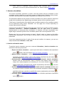
3.2 Cameras management
To perform interior orientation you should specify cameras for images used in a project and
input their passport data.
In common case there is a following workflow:
- create cameras list of a project and input their parameters;
- assign cameras to project images;
- specify cameras axes directions for project images.
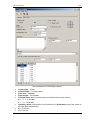
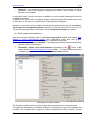
Manage project cameras window is opened by pushing the button
on AT toolbar or
using menu command Orientation | Manage cameras. The window is used for input and
editing of cameras parameters, creating of cameras list for current project and assigning of
cameras to images from the images list, if images block contains images, acquired by
different cameras.
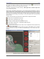
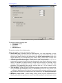
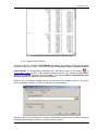
Manage project cameras window
Left part of the window called Project images panel contains a list with all strips/images of
the project and their parameters, as well as tools for images selection.
You can select images using different ways. To select particular images, mark the
appropriate checkbox. To select all images of the strip, mark the appropriate checkbox for
the strip. There are the following tools for images selection:
7
RACURS Co., Ul. Yaroslavskaya, 13-A, office 15, 129366, Moscow, Russia
PHOTOMOD 5.21
- select all images in the list;
- cancel all images selection;
- invert images selection;
- select highlighted images;
- cancel selection of highlighted images;
- select those images in the list, which are highlighted in block scheme in 2D
window;
- highlight in block scheme in 2D window the images selected in the list.
To highlight an image click the image name in the list. The highlighted image is shown in
view window in the right part at the bottom. To highlight several images use Ctrl and Shift
keys.
Project images have the following parameters displayed in the list – interior orientation state
(+ or -), a name of assigned camera and camera axes rotation angle.
The Project cameras panel of the window is used for project cameras management and
contains the following:
– tools to input/edit camera parameters and creating of cameras list for current project,
– window with cameras list of current project,
– the Change cameras for selected images section used to assign cameras to images
and to specify cameras axes directions for selected images,
– view window for the image highlighted in the list.
You can input cameras parameters and create the images list of the current project using the
following tools:
– New camera. Opens the Camera window used to input camera’s passport
data. After the input is completed click OK. The new camera name is shown in
cameras list, and the Cameras subfolder, which contains <Camera name.x-cam>
file, is created in active profile resources in current project folder. Besides, the
Camera window provides opportunity to import camera parameters from external files
or from active profile resources and to export camera parameters to file/resource.
See the chapter Cameras parameters import and export.
– Import camera from another project of active profile. Opens the Open
window displaying all resources of active profile to select camera from another
project. Select x-cam-file in another project folder in Cameras subfolder. Click Open.
The camera selected is shown in the list.
– Edit camera parameters for the camera selected in the list. Opens the
Camera window to change parameters of camera selected in the list. You can edit all
parameters except camera name. Besides, the Camera window provides opportunity
to import camera parameters from external files or from active profile resources and
to export camera parameters to file/resource. See the chapter Cameras parameters
import and export.
– Copy camera – to create copy of camera selected in the list. Opens the Copy
the camera window to input a new name for camera selected. Input a new name or
confirm the existing one, then push OK. Camera copy is shown in the list.
© 2011
8
Aerial triangulation
2011
– Rename camera selected in the list. Opens the Rename the camera window.
Input a new name or confirm the existing one, then push OK. Camera new name is
shown in the list.
– Delete camera selected in the list.
– Unassign camera for selected images. At that in cameras list, the Number
of images column shows ”0” value.
For more details on input of film and digital cameras parameters refer to the appropriate
chapters Input and editing of film camera parameters and Input of digital camera parameters.
In window of cameras list you can see names of current project cameras and number of
images assigned to particular project cameras.
The Change camera for selected images section contains the following options:
Assign selected camera to selected images;
Set camera rotation to selected images.
In order to assign camera to selected images:
– select camera in project cameras list;
– select images in в project images list;
– select the Assign selected camera to selected images checkbox;
– push the Execute button.
In order to rotate camera axes according to passport data:
– highlight images in images list of the project, that needed to be rotated (use images view
window);
– select the Set camera rotation to selected images checkbox and specify a rotation
angle;
– push the Execute button.
Section for highlighted image view contains image name, window for selected image view
displaying also camera axes in the image and toolbar used to pass to interior orientation
stage and to open interior orientation report.
After specifying of project cameras and assigning cameras to images, you can proceed to
interior orientation stage. See the chapter Interior orientation of film camera images or
Interior orientation of digital camera images.
3.2.1 Input and editing of film camera parameters
You can input/edit parameters of film camera assigned to a current project using Manage
project cameras window. Push the button
(see the chapter Cameras management) to
open the window and then push the button
(New camera) or
opened Camera window you can fill in or edit the following fields:
9
(Edit camera). In the
RACURS Co., Ul. Yaroslavskaya, 13-A, office 15, 129366, Moscow, Russia
PHOTOMOD 5.21
Film camera parameters
Camera – input arbitrary name of camera.
Camera type – specify camera type: film or digital (see the chapter Input of digital
camera parameters).
Focal length – input focal length in mm.
Calibration date – input date of camera calibration.
Principal point – input principal point coordinates in mm.
Description – camera description that is helpful to identify the camera and projects in
which it has been used.
Fiducial marks – is selected according to the available camera calibration data:
– Principal point only – is setup by Xo and Yo coordinates in mm. Used for
interior orientation, if there are no calibration data and fiducial marks available.
© 2011
10
Aerial triangulation
2011
– Fiducial marks – is used for interior orientation, if there are no calibrated
fiducial marks coordinates or calibrated distances available, but it is possible to
calculate the principal point at the intersection of the segments, joining the
fiducial marks.
– Calibrated distances – allows to input calibrated distances between fiducial
marks in mm on XY axes – Lx and Ly.
– Fiducial coordinates – allows to input calibrated X, Y coordinates of the
fiducial marks, if they are available in camera passport.
Fiducial coordinates type – if you use calibrated distances and fiducial marks
coordinates, you can select fiducial marks type – fiducial marks-template from
drop-down list, if the list contains suitable camera. Selected template already
includes fiducial marks data, specific for selected camera type, – marks
numeration, marks template and marks searching area. That is why you can
perform interior orientation immediately in automatic mode. See the chapter
Automatic interior orientation.
Distortion – is selected according to available camera distortion data in camera
passport. In the list opened choose one of the following:
– No data – no distortion data available
– Formula – input a set of Brown-Conrady model coefficients
– Radial – input a set of distortion values depending on distances from the
principal point
– 4 directions “+” – input a set of distortion values along the axes of the image
coordinate system
– 4 directions “X” – input a set of distortion values along the diagonal
directions
– 8 directions – input a set of distortion values along the axes of the image
coordinate system and diagonal directions.
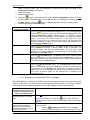
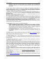
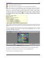
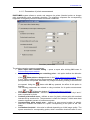
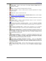
When entering the distortion data you should input the point of symmetry coordinates (zero
distortion point in mm) and the distortion data in microns in either as a table or a formula.
The screenshot above shows the example of distortion data along diagonal directions.
Directions orientation is shown on scheme to the right from distortions table. You should
input to each table row: distance from the point of symmetry – radius (first column) and
distortion values the distortion values in the other columns corresponding to the different
directions. To add, delete or edit lines, use the set of buttons below the table:
– Add line to the table (Ctrl-Ins shortcut);
– Delete line selected in the table (Ctrl-Del shortcut);
– Change sign;
– Multiply by 1000 (to multiply distortion value by 1000, use it to put distortion
values in the table to microns);
– Divide by 1000 (to divide distortion value by 1000, use it to put distortion
values in the table to microns).
Note. Positive distortion coefficients mean image “shift” from center
3.2.2 Input of digital camera parameters
You can input/edit parameters of digital camera assigned to a current project using Manage
project cameras window. Push the button
(see the chapter Cameras management) to
open the window and then push the button
(New camera) or
11
(Edit camera). In the
RACURS Co., Ul. Yaroslavskaya, 13-A, office 15, 129366, Moscow, Russia
PHOTOMOD 5.21
opened Camera window input the camera name to appropriate field. In Camera type field
specify camera type – digital.
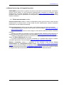
When input digital camera parameters remember that all of them (principal point coordinates,
focal length, point of symmetry (zero distortion point)) should be input in mm, but pixel size
and distortion coefficients – in microns.
In Point of origin section specify a point of origin position, used to calculate a shift of a
principal point and a point of symmetry to consider a distortion from camera passport:
– in lower left corner – in center of lower left pixel;
– in image center.
Input of digital camera parameters
© 2011
12
Aerial triangulation
2011
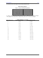
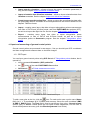
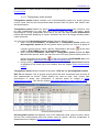
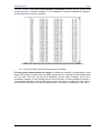
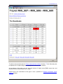
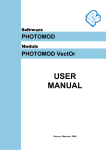
The example below shows digital camera (DSS) parameters input.
DSS Camera passport
Table 1. Camera Calibrated Parameters
Parameter
f (mm)
xPP (pixels) +
yPP (pixels) +
xPPC (mm) ++
yPPC (mm) ++
+
Value
54.995
2011.49
2018.91
-0.243
0.244
xPP and yPP are measured from image upper left corner, (image size 4077x4092), see Fig.8
xPPC and yPPC are measured from image center (pixel size = 9 microns), see Fig.8
++
Table 2. Radial Lens Distortion
Radial Distance (mm)
1
2
3
4
5
6
7
8
9
10
11
12
13
14
15
16
17
18
19
20
21
22
23
24
25
26
13
Radial Distortion (Pixel)
-0.00
-0.02
-0.07
-0.16
-0.31
-0.54
-0.86
-1.29
-1.84
-2.53
-3.37
-4.37
-5.55
-6.93
-8.50
-10.27
-12.22
-14.42
-16.79
-19.34
-22.04
-24.87
-27.80
-30.73
-33.61
-36.35
Radial Distortion (microns)
-0.022
-0.180
-0.607
-1.441
-2.833
-4.897
-7.783
-11.589
-16.571
-22.747
-30.287
-39.313
-49.937
-62.376
-76.486
-92.419
-110.024
-129.783
-151.116
-174.056
-198.395
-223.839
-250.233
-276.592
-302.506
-327.179
RACURS Co., Ul. Yaroslavskaya, 13-A, office 15, 129366, Moscow, Russia
PHOTOMOD 5.21
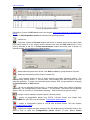
Notation:
Xi and Yi: Image Coordinate Frame – Right Handed System
XP and YP: Pixel/Monitor Coordinate Frame – Left Handed System
Point Offsets in a DSS Digital Image
Note. In given example, symmetry point (with zero distortion) coincides with the
principal point
In Cameras window input the following values:
© 2011
14
Aerial triangulation
2011
Input parameters of DSS digital camera
15
Camera type – Digital
Point of origin – in image center
Pixel size – 9 micron
Focal length – 54.995 mm
Principal point (shift of principal point coordinates from image center):
X = x i pp = - 0.243 mm
Y = y i pp = 0.244 mm
Symmetry point (coordinates of zero distortion) in Distortion section (the same as
principal point coordinates):
X= - 0.243 mm,
Y= 0.244 mm
RACURS Co., Ul. Yaroslavskaya, 13-A, office 15, 129366, Moscow, Russia
PHOTOMOD 5.21
Radial distortion – according to camera passport
Note. Survey should be performed with the same camera resolution and focal length,
that were used during camera calibration (if camera allows to perform survey with
different resolutions).
After you have completed correct input of digital camera parameters, you can immediately
perform interior orientation. See the chapter Interior orientation of digital camera images.
3.2.3 Cameras parameters import and export
You can import camera parameters from x-cam-file of file system or from active profile
resources.
To start camera parameters import from files/resources open the Camera window from
Cameras management window, using the button
(New camera) or
(Edit camera),
and select menu commands Import | From file or Import | From resource.
In case of importing from file, the Load camera window is opened. You should select
necessary file with camera parameters (with x-cam extension) on local/network disks (i.e.
exterior file, which is not a resource of active profile) and push OK. All parameters of
selected camera will be loaded to appropriate fields.
In case of importing from file, the Open window is opened, where you can see a tree of
active profile resources. Select the file from resources with camera parameters (with x-cam
extension) and push OK. Files with cameras parameters are stored by default in Cameras
folder in each profile project. All parameters of selected camera will be loaded to appropriate
fields.
To perform camera parameters export select menu commands Export | To file or Export
| To resource in Camera window.
File with *.x-cam extension has contents as follows:
© 2011
16
Aerial triangulation
2011
Camera parameters file format x-cam
The x-cam-file contains fields corresponding to the Camera dialogue parameters: Name –
camera name; CalibrationDate – date of calibration; Description – camera description; Focus
– focal length; PrincipalPoint – principal point’s coordinates, etc.
See also the chapters Input and editing of film camera parameters and Input of digital
camera parameters.
3.3 Interior orientation of film camera images
You can use three methods of interior orientation of images assigned to film camera (see the
chapters Cameras management and Input and editing of film camera parameters):
- measure fiducial marks manually and perform interior orientation (see the chapter Manual
measuring of fiducial marks);
- perform interior orientation in semiautomatic mode using a template image, which has
already measured fiducial marks and interior orientation completed (see the chapter
Semiautomatic interior orientation);
- perform automatic interior orientation, if camera parameters contain Fiducial coordinates
type specified, which includes data on fiducial marks location, templates and numeration
(see the chapter Automatic interior orientation).
17
RACURS Co., Ul. Yaroslavskaya, 13-A, office 15, 129366, Moscow, Russia
PHOTOMOD 5.21
3.3.1 Manual measuring of fiducial marks
After you have specified film cameras for project images you can proceed to stage of fiducial
marks measuring (if any) and in that way perform images interior orientation.
For manual measuring of fiducial marks on image you should select the image in Block
scheme window and push the button
(or use menu command Orientation | Interior
orientation | Manual interior orientation). The Interior orientation window used for
fiducial marks measuring appears. You can also open this window from the Manage project
cameras window (see the chapter Cameras management).
Fiducial marks measuring
The toolbar at the upper part of the window allows to perform the following operations:
,
,
,
,
- to switch to adjacent image in the block - left, up, down or right;
– to switch to previous or next unmeasured image;
- opens Manage project cameras window;
- opens Semiautomatic interior orientation window;
- opens Automatic interior orientation window;
– opens Report on interior orientation;
– to delete all fiducial marks measurements on current image;
– opens Marker settings window allowing to adjust shape, size and color of marker.
In Image information and Camera information panels you can see general information on
the image and camera parameters.
© 2011
18
Aerial triangulation
2011
In status bar you can always see the scale of the image shown in main window or
“lens”-window and marker coordinates (in pixels). When you have measured 2 fiducial
marks, the status bar will show also the marker coordinates on the image (in mm)/ the
marker coordinates on the image (in mm) considering distortion and pixel size (in mm).
Scroll bars in main window and "lens"-window are turned on and off with Ctrl-F8 hotkey.
The procedure of fiducial marks measurement and interior orientation perform
Select image using the buttons
,
,
,
,
,
. The table with (X, Y) coordinates
of fiducial marks in millimeters taken from camera passport will be shown at the lower part of
the window. After interior orientation is completed for cameras with known fiducial marks
coordinates, the table will show fiducial marks coordinates Xр and Yр (in pixels) and residual
errors of fiducial marks coordinates Ex and Ey (in mm).
To measure fiducial marks you should select a fiducial mark to be measured in fiducials
table. Then place the marker precisely on the selected fiducial mark on the image. Marker
position coordinates in pixels are shown in Marker coordinates (pix.) section. Marker
position coordinates in millimeters are shown in Marker coordinates (mm) section. For
searching fiducials on image and precise marker position use the buttons of upper toolbars in
images view windows:
- image zoom out (duplicated by the / key);
- image zoom in (duplicated by the * key);
- fit image to window (duplicated by Alt-Enter shortcut);
- show image in original size 1:1 (duplicated by Alt-1 shortcut);
- center image on marker.
To move image in the window in panning mode use mouse, holding pressed Alt key.
To fix measurement push the button
. After that you will see the result
of measurement in the Measurements table – fiducial mark coordinates Xр and Yр (in
pixels). Use the button
to delete measurement.
Once first two fiducial marks have been measured the marker is automatically positioned
approximately at the 3-d and subsequent fiducial marks. At that the marker is placed in a
neighborhood of a next mark on the image.
When 2 fiducial marks have been measured you can see the following in status bar:
information on pixel size, marker coordinates on the image in pixels and in millimeters, and
marker coordinates measured considering distortion (in mm).
After all fiducial marks on the image have been measured you should select a transformation
type to be applied.
Select one of transformation types from a list in Transform type panel:
Rotation, scale, shift;
Affine;
Projective.
See also the chapter Interior orientation.
Push the button
19
to perform interior orientation.
RACURS Co., Ul. Yaroslavskaya, 13-A, office 15, 129366, Moscow, Russia
PHOTOMOD 5.21
As a result of interior orientation you can see residuals values Ex and Ey (in mm) between
input and measured coordinates in fiducials table. Acceptable value of maximal residual error
should not exceed a pixel size. You can perform accuracy control and obtain more details on
interior orientation results of the image by pushing the button
which allows to view a
report on interior orientation. See also the chapter Report on interior orientation.
When you have finished fiducial marks measurement on at least one of the block images,
you can perform interior orientation for the rest of images in semiautomatic mode. See the
chapter Semiautomatic interior orientation.
3.3.2 Semiautomatic interior orientation
Before starting semiautomatic interior orientation process you must perform manual interior
orientation at least for one image (see the chapter Manual measuring of fiducial marks).
Algorithm of semiautomatic interior orientation searches/measures fiducial marks on project
images according to selected template (the image with already performed interior orientation,
which fiducial marks are used as templates), and then calculates interior orientation
according to selected transformation type.
To perform semiautomatic interior orientation mode push the button
or use menu
command Orientation | Interior orientation | Semiautomatic interior orientation. After
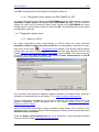
that the window used to setup interior orientation in semiautomatic mode appears.
Semiautomatic interior orientation window
The first image with performed interior orientation is marked in the list as Template. If there
are other images with performed interior orientation you can select another template. To do
© 2011
20
Aerial triangulation
2011
this, select the image by clicking its name and push the button
Template note to the left from the image name in the table.
. You will see the
Then setup 2 parameters for marks searching – Mark region size and Search region size,
using corresponding sliders.
Search region size should be big enough to “cover“ fiducial mark area especially in cases of
cutting or scanning film images differently (when corresponding fiducial marks are located at
different distances from the image edge). Mark region size defines mark’s template and must
include the mark completely. Search region and Mark region are displayed by rectangles
(one external and two internal for the mark), in the “lens“-window and in the main view
window as well.
To define searching areas use the buttons of upper toolbar in images view window:
- image zoom out (duplicated by the / key);
- image zoom in (duplicated by the * key);
- fit image to window (duplicated by Alt-Enter shortcut);
- show image in original size 1:1 (duplicated by Alt-1 shortcut);
- center image on marker.
You can adjust marker parameters (size, shape, color) in appropriate window opened using
the
button of upper toolbar.
To move image in the window in panning mode use mouse, holding Alt key. Also, scrollbars
may be used which are shown and hidden with Ctrl-F8 hotkey in main window and "lens"windows.
Specifying of marks searching area and mark template
21
RACURS Co., Ul. Yaroslavskaya, 13-A, office 15, 129366, Moscow, Russia
PHOTOMOD 5.21
Semiautomatic interior orientation means searching of the same (by the mark template)
objects – fiducial marks on selected images of the block.
The system is looking for fiducial marks using a correlation process, which compares a mark
image with a template. Acceptable correlation coefficient threshold is set by the Correlation
coefficient parameter (0.85 by default).
Section Search for marks is used to define images on which the system will search for
marks and measure them. There are the following options:
- search for marks on selected images only.
- search for marks on all project images.
Select Search images with int. or. already performed checkbox to include into the search
those images, which already have interior orientation performed, i.e. to recalculate their
interior orientation according to selected template.
To select images in the list of Project images section check boxes to the left from
image/strip name or use upper toolbar buttons that allows the following:
- select all images in the list (
button);
- cancel all images selection in the list (
- invert images selection (
- select highlighted images (
button);
button);
button);
- cancel highlighted images selection (
button);
- select images in the list, selected in block scheme in 2D window (
button);
- selected in block scheme in 2D window the images selected in the list (
button).
In order to select an image click image’s name in the list. To select several images hold Ctrl
and Shift keys.
After images selection you should specify one of the following transformation types:
Rotation, scale, shift;
Affine;
Projective.
See also the chapter Interior orientation.
To perform semiautomatic interior orientation, push the button Start. You can perform
accuracy control and obtain more details on results of image interior orientation by pushing
the button
which allows to view a report on interior orientation. See also the chapter
Report on interior orientation.
Semiautomatic interior orientation window also contains buttons used to open the following
windows:
- Cameras management (the button
);
- Manual measuring of fiducial marks – manual measuring of fiducial marks (the button
- Automatic interior orientation (the button
© 2011
);
).
22
Aerial triangulation
2011
3.3.3 Automatic interior orientation
You can perform automatic interior orientation of images acquired by film camera, if Fiducial
coordinates type is specified in the camera’s parameters. See the chapter Input and editing
of film camera parameters. To perform correct automatic interior orientation you should
specify correct camera’s axes orientation for images. See the chapter Cameras
management.
Algorithm of automatic interior orientation searches/measures fiducial marks on project
images automatically in accordance with specified fiducial coordinates type, and interior
orientation measuring. Abovementioned parameter Fiducial coordinates type already
contains an information on fiducial marks, specific for camera selected, – marks numbering,
mark template and marks searching area. The current system version supports fiducial
coordinates types for the following cameras: RC 20, RC 30 and LMK.
To perform automatic interior orientation click the button
on toolbar or use menu
command Orientation | Interior orientation | Automatic interior orientation. After that the
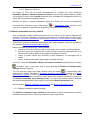
window allowing to make settings for automatic interior orientation procedure appears.
Automatic interior orientation window
Select images to perform interior orientation. Right part of the Project images window
contains a list of all project strips and images, and tools for images selection.
To select image in the list, check box to the left from the image or strip name (in the latter
case you will select all images of selected strip) or use upper toolbar buttons that allows to
do the following:
23
RACURS Co., Ul. Yaroslavskaya, 13-A, office 15, 129366, Moscow, Russia
PHOTOMOD 5.21
- select all images in the list;
- cancel all images selection in the list;
- invert images selection;
- select highlighted images;
- cancel highlighted images selection;
- select images in the list, selected in block scheme in 2D window;
- selected in block scheme in 2D window the images, selected in the list.
In order to select an image click image’s name in the list. To select several images hold Ctrl
and Shift keys.
Upper toolbar of the left part of the window contains buttons used to open the following
dialogues:
- Cameras management, where you can control camera’s axes direction on images and
adjust cameras parameters to perform automatic interior orientation correctly (the
button);
- Manual measuring of fiducial marks for manual measuring of fiducial marks (the
button);
- Semiautomatic interior orientation to perform interior orientation in semiautomatic mode (the
button);
- Report on interior orientation (the
orientation procedure.
button) to perform quality control of interior
In the right part of the window you can setup Mark search parameters.
Specify correlation coefficient threshold. The system is looking for fiducial marks using a
correlation process, which compares a mark image with a template. Acceptable correlation
coefficient threshold is set by the Correlation coefficient parameter (0.80 by default).
Section Search for marks is used to define images on which the system will search for
marks and measure them. There are the following options:
- search for marks on selected images only.
- search for marks on all project images.
Select Search images with int. or. already performed checkbox to include into the search
those images, which already have interior orientation performed, i.e. to recalculate their
interior orientation.
After images selection you should specify one of the following transformation types:
Rotation, scale, shift;
Affine;
Projective.
See also the chapter Interior orientation.
To perform semiautomatic interior orientation, push the button Start. You can perform
accuracy control and obtain more details on results of image interior orientation by pushing
the button
which allows to view a report on interior orientation. See also the chapter
Report on interior orientation.
© 2011
24
Aerial triangulation
2011
If you have obtained unsatisfactory results you can delete interior orientation measurements.
To do this, select menu command Orientation | Interior orientation | Delete interior
orientation data. After that you will see the window allowing to select images where the
interior orientation data will be deleted.
3.4 Interior orientation of digital camera images
When performing interior orientation of images acquired by digital camera you should input
cameras parameters correctly from the camera passport into appropriate fields of Camera
window. Please remember that all of parameters should be input in the same units in
Camera window – either in pixels or in millimeters. You should also specify a point of origin
position, used to calculate a shift of a principal point and a point of symmetry (zero distortion
point) – in lower left pixel or in the image center. See the chapter Input of digital camera
parameters.
Interior orientation of the image acquired by digital camera means measuring of
principal point location regarding to center of left lower pixel of the image.
Then you should assign the camera to images and specify camera’s axes directions for
selected images in Cameras management dialogue window.
To perform interior orientation of images acquired by digital camera click OK in Camera
window. This will start interior orientation operation – calculation of principal point
coordinates regarding to lower left pixel center. You can view interior orientation results by
pushing the button
(Report on interior orientation). You can perform or recalculate
interior orientation using the button
or menu command Orientation | Interior
orientation | Calculate interior orientation.
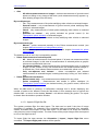
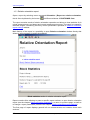
3.5 Report on interior orientation
Report on interior orientation provides detailed information about selected parameters and
calculation results of interior orientation and allows to keep under control the interior
orientation quality.
To view interior orientation report push the button
or select menu command Orientation
| Interior orientation | Report on interior orientation. The Report on interior orientation
dialogue window is opened.
25
RACURS Co., Ul. Yaroslavskaya, 13-A, office 15, 129366, Moscow, Russia
PHOTOMOD 5.21
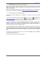
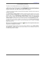
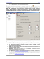
Main parameters of report on interior orientation
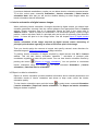
This window contains two tabs where you can setup main and additional parameters.
The Main parameters tab is used for specifying the following report parameters:
Show report for all images or for selected ones
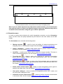
Setup a threshold on interior orientation residuals for RMS, mean or maximal errors in
pixels or mm.
Residuals calculation:
If your images were scanned using photogrammetric scanner, mean absolute value E mean
should not exceed a half of pixel. Approximate ratio of mean, maximum error and root mean
squared errors:
E max 2 E mean
where E mean - mean error, E max
RMS 2 E mean
- maximal, RMS - root mean squared error.
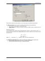
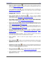
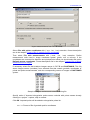
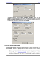
The Additional parameters tab is used for specifying the additional report parameters:
Show residuals with fixed point format or in exponential format
Show residuals with normal, high or maximal precision
© 2011
26
Aerial triangulation
2011
Additional parameters of report on interior orientation
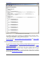
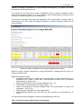
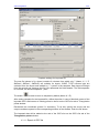
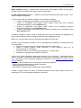
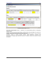
After you click OK the report containing general information on interior orientation operation
is opened. Here you can see what strips and images are passed interior orientation and what
part of the procedure has been completed. There are also shown values of errors of fiducial
marks measurements acceptable from specified threshold point of view.
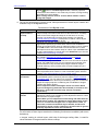
Report on interior orientation for film camera
Strips and images which are not passed interior orientation procedure yet, are highlighted by
red color, strips and images, for which interior orientation is done incompletely or with
27
RACURS Co., Ul. Yaroslavskaya, 13-A, office 15, 129366, Moscow, Russia
PHOTOMOD 5.21
mistakes, exceeding a threshold, or if not all marks are measured – by yellow. The errors
themselves are also marked by red.
The example on the figure above shows unsatisfactory result of interior orientation, where
mean error was setup in pixels – 0.2, one of marks on one of images was not measured, and
all marks on another image were not measured too.
To proceed to necessary strip select the appropriate link in strips table. In images table of
selected strip use a link to pass to detailed information on interior orientation results for the
image selected.
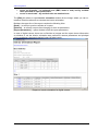
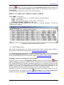
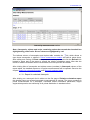
Report on interior orientation for an image acquired by film camera
Report on image contains information on camera parameters, including pixel size (mm) and
interior orientation data.
Measurements table shows:
Acceptable maximal error, resulting from specified value in report parameters (if you
specified limit for RMS or mean abs., the acceptable maximal error is calculated
automatically) in pixels or mm.
Marks coordinates taken from camera passport in mm – X,Y
Coordinates of measurements on image in pixels – X,Y
Values of discrepancies between passport data and measurements in pixels and
millimeters – Ex, Ey, Exy
Residual value specified in the report parameters
Mean RMS and maximal error values Ex, Ey, Exy in pixels or mm calculated for all
marks.
The values that exceed acceptable residuals are highlighted by red color.
Thus, red color in report always shows the following:
© 2011
28
Aerial triangulation
2011
errors on all marks – by selected error (RMS, mean or max) and by residual
value specified in report parameters
errors on each mark – by residual value on maximal error.
The [Edit] link allows to open Interior orientation window for the image, where you can remeasure fiducial marks and re-calculate the interior orientation.
Besides, the upper line of the report contains the following links:
[Back] – to return to previous window of a report
[Refresh] – to refresh a report after changing of some its parameters
[Report parameters] – opens window to edit the report parameters
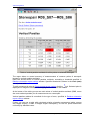
In case of digital camera, there are no fiducials on images and the report shows information
on whether or not the interior orientation was performed, camera parameters and principal
point coordinates calculated relatively lower left pixel center.
Report on interior orientation for digital camera
29
RACURS Co., Ul. Yaroslavskaya, 13-A, office 15, 129366, Moscow, Russia
PHOTOMOD 5.21
Report on interior orientation for an image acquired by digital camera
All the report windows (for the whole block or for the image) contain upper toolbar with the
following buttons:
– search by word or its part;
– allows to save a report in HTML-file in any folder of file system;
– allows to save a report in HTML-file in active profile resources;
– allows to print a report;
– opens print preview window.
4. Relative orientation and ground control points measurement
To perform aerial triangulation on stereopairs you need to measure a set of tie points on
overlapping images (in addition to ground control points, see the chapter Input and
measuring of ground control points). Tie points are used to create models from pairs of
adjacent images and to create from these models the whole strip model or the entire block
model.
If the block adjustment purpose is only calculating the image exterior orientation parameters,
it is not necessary to select tie points on recognizable details of a terrain, because tie points
on overlapping images are measured either automatically using the correlation algorithm or
stereoscopically by an operator.
© 2011
30
Aerial triangulation
2011
If you perform aerial triangulation to measure ground coordinates and heights of some points
on images, which afterwards can be used as ground control points in further
photogrammetric processing of single images and stereopairs, you should choose the tie
points on recognizable terrain details. Such points are referred to as targeted points below.
Measuring of a tie point means its stereoscopic measuring on both images of a stereo pair at
the same time (or on several images which contain the point).
Stereoscopic measuring can be performed manually in Relative orientation module (see the
chapter Manual measuring of triangulation points) in three following ways:
by manual positioning of the point on each of two images;
by manual positioning of the point on one image and transferring the marked point to
another image with correlator;
by manual positioning of the point in stereo mode in 3D space.
by automatic positioning of the point on both images using correlator.
Besides, tie points can be measured in full automatic mode on selected images of a block.
See the chapter Automatic tie points measurement.
Note: Ideally, for relative orientation executing you should combine two methods –
automatic measurement with “bad” points filtering and manual mode for editing of
measurements acquired in automatic mode and adding of new points to obtain
satisfactory results.
Automatic mode provides a range of possibilities to perform relative orientation of block
images – combinations of a number of parameters for tie points measurement, transfer and
filtering using different criteria that can bring satisfactory results even without manual
measurements.
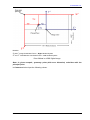
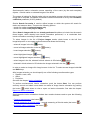
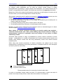
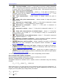
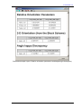
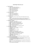
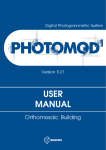
When using only manual procedures of relative orientation, the optimal way for block
measurement is considering of tie points placement in 6 standard zones for each stereopair
(at least 2 points for each zone).
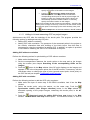
3
2
4
1
image principal point
tie points location zones
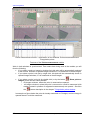
Recommended zones for measuring tie points inside strips
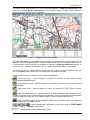
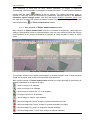
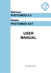
In order to consolidate images strips into block it is recommended to place inter-strip tie
points in inter-strip overlap zones on both sides from midline of overlap area.
31
RACURS Co., Ul. Yaroslavskaya, 13-A, office 15, 129366, Moscow, Russia
PHOTOMOD 5.21
Recommended location of tie points in inter-strip overlapping area
Note. If you use block adjustment by independent models method, you should transfer
inter-strip tie points to at least one adjacent image in each strip. Otherwise they will be
not taken into account when using this type of block adjustment.
4.1 Orientation menu
In order to perform data collecting for aerial triangulation procedure use the Orientation
menu. Its menu items are partly duplicated by the buttons of the main toolbar and the AT
toolbar.
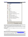
The Orientation menu includes the following items:
Manage cameras
– used for input and editing of cameras parameters and
assigning them to current project images. See the chapter Cameras management.
Interior orientation – contains menu items used to perform interior orientation
procedure. See the chapter Interior orientation menu.
QuickTies – contains menu items used to match the images manually. This data is
used to build the block layout. See the chapter Manual matching of images.
Tie points list
– allows to open a list containing all measured triangulation
points (ground control, control, tie) with measurements data. See the chapter
Triangulation points window.
GCP points list
– allows to open a list of all measured and non-measured
ground control points with their input coordinates (without measurements data). See
the chapter Triangulation points window.
Delete points measurements
– allows to select triangulation points types for
deletion and delete them. See the chapter Point measurements deletion.
Clear point catalogue – allows to delete all triangulation points (GCP, check, and
tie) from points catalogue at once.
Automatic tie point measurement
– allows to perform tie points measurement
in automatic mode. See the chapter Automatic tie points measurement.
© 2011
32
Aerial triangulation
33
2011
– used to open a report containing results of
Report on relative orientation
relative orientation of images for analysis and removal of measurements errors. See
the chapter Relative orientation report.
Load triangulation points
– used to load triangulation points to the 2D window
and allows to set up points displaying of the certain type. See also the chapter
Displaying points in 2D window.
Automatic UAV triangulation – allows to measure tie points on UAV images in
automatic mode.
Open selected images for measurement
– allows to open the Points
measurement module used for points measurement on selected images in manual
mode. See the chapter Manual measuring of triangulation points.
– allows to open the Points measurement
Open images containing marker
module used for points measuring in manual mode on images, which contain marker
position. See the chapter Manual measuring of triangulation points.
– allows to open the Points measurement module
Open in-strip stereopair
used for points measuring in manual mode on selected stereopair of a strip. See the
chapter Manual measuring of triangulation points.
– allows to open the Points measurement module
Open inter-strip stereopair
used for points measuring in manual mode on selected inter-strip stereopair. See the
chapter Manual measuring of triangulation points.
Exterior orientation data list
– allows to open the Exterior orientation
parameters window with exterior orientation parameters, which were imported or
entered manually. See the chapters Import of exterior orientation data, Exterior
orientation data list.
Load projection centers as vectors – allows to transform projection centers data to
point vector objects and load them to the 2D window for analysis.
Select subblock – allows to select the project images to perform the block
adjustment.
Block adjustment
– allows to set the adjustment parameters, perform block
adjustment and display the adjustment results to view and correct them (see Block
adjustment User Manual).
Adjustment in batch mode
– allows to set the adjustment parameters and
adjust the block without displaying the adjustment results and to view and correction
of residuals (see Block adjustment User Manual).
Direct georeferencing
– allows to adjust the block from the imported exterior
orientation parameters. (see the chapter Import of exterior orientation data).
Delete adjustments results – allows to delete all the adjustment results (see Block
adjustment User Manual).
RACURS Co., Ul. Yaroslavskaya, 13-A, office 15, 129366, Moscow, Russia
PHOTOMOD 5.21
Import exterior orientation – allows to import the exterior orientation parameters, if
any (see the chapter Import of exterior orientation data).
Import orientation from UltraCam metadata – allows to import orientation data from
UltraCam metadata. See the chapter Import from UltraCam metadata.
Create images georeferencing files – allows to export the georeferencing data after
the preliminary exterior orientation or block adjustment into the ArcInfo World File and
MapInfo TAB files format.
Import – contains menu items, that allow to import triangulation points measurements
from files of PAT-B and X-Points format, and from PHOTOMOD 4.x projects (XPT),
as well as to import the flight line file. See the chapter Triangulation points import.
Export – contains menu items, that allow to export triangulation points
measurements to files of PAT-B and X-Points format, as well as to export
triangulation points to Geomosaic program. See the chapter Triangulation points
export.
4.2 Input and measuring of ground control points
Ground control points are processed in two stages – first you should input GCP coordinates
and then recognize and measure them on the block images.
4.2.1 GCP input
You can input ground control points using GCP list tab of Triangulation points window, that is
opened by:
menu command Orientation | GCP points list
the
GCP list tab
button of the main PHOTOMOD Core toolbar
of Points measurement module.
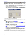
Window for GCP coordinates input
To add a new point to the list, click the
icon. For each point enter a point name (Name
field), its X, Y, Z coordinates (X, Y, Z fields) and accuracy values for each coordinate (RMS
X, RMS Y, RMS Z fields). The Type field is used to set the type for a point – Ground control
(default type) or Check. Control points are not used in block adjustment, but are used to
check the adjustment accuracy (see also Block adjustment User Guide).
© 2011
34
Aerial triangulation
2011
PHOTOMOD system works with plain-height (X,Y,Z), plain (X,Y) and height (Z) point’s
coordinates. During input of Z or XY points in field with no coordinates, “0” value appears by
default. Use the buttons
,
to exclude appropriate coordinates when input plain or
button is used to input of all
height points (the appropriate field becomes empty). The
three coordinates.
You can edit the coordinates, accuracies and point’s type by clicking the appropriate field.
Beside manual input of coordinates values you can use coordinates import from text file (see
the chapter Import of GCP list).
After coordinate points input you can proceed to their measurement on images stage (see
the chapter GCP measurement).
The toolbar of GCP catalog window is used for the following operations:
– enable editing mode for GCP
– GCP search by its name
– new point adding
– selected points deletion (editing mode should be disabled). Deletes points selected in
the list along with all their measurements.
– deletion of all input GCP
– import of GCP list from text file (see the chapter Import of GCP list)
– export of GCP list to text file (see the chapter Export of GCP list)
– swap X and Y coordinates for selected or for all points
– recalculate coordinate system for selected or for all points
– use all three coordinates for XYZ points (by default). It is used to restore excluded
coordinates values, if one of two types were applied to a point – Z or XY point
– is used for a planimetric points, it excludes Z coordinate (the Z coordinate value is
shown in grey color). The field is editable. After editing of the excluded Z value it is
automatically turned on (i.e. it will be involved into adjustment).
– is used for a vertical point, it excludes X and Y coordinates (the coordinates values are
shown in the appropriate fields in grey color). The fields are editable. After editing of the
excluded X and Y values they are automatically turned on (i.e. they will be involved into
adjustment).
– opens the Set control points coordinates accuracy window used to associate
accuracy values (RMS) by XY or Z coordinate to all or to selected GCP
– find/measure selected point. The button click is duplicated by double click on selected
point. Shows GC point in Points measurement module on images where it is measured, or
shows the images where it can be measured (with marker located in the place of supposed
measuring). If the point is not measured, the system shows its appropriate images after
measuring of first 2-3 GC points or in case if preliminary orientation was performed in
geodetic coordinate system (by projection centers, for instance).
– opens relative orientation report (see also the chapter Relative orientation report).
35
RACURS Co., Ul. Yaroslavskaya, 13-A, office 15, 129366, Moscow, Russia
PHOTOMOD 5.21
– allows to open DEM used for extraction of Z-coordinate for GCP selected in the list (if
they are not available, for instance). Name of opened DEM and its path appears in status
line. The button for DEM closing is in the same place.
– allows to obtain Z-coordinates from DEM for selected points
Note. For adjustment of airborne images block you should have projection centers
coordinates or at least 3 ground control points. Every point should be measured on at
least 2 images on stages of strip ties and images tie points measurements. About
number of GCP for adjustment of scanner images blocks see the chapter Number of
GCP necessary for space images processing in PHOTOMOD.
Note. GCP coordinates are given in the coordinate system selected during project
creation in PHOTOMOD Core (see Project creation User Guide).
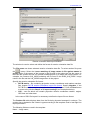
4.2.1.1 Import of GCP list
Text file suitable for GCP import to PHOTOMOD system should contain strings like following:
NAME,X,Y,Z,STDDEVX,STDDEVY,STDDEVZ
0556,4971037.270000,6444373.220000,129.630000,0.10000, 0.1000000, 0.1000000
0911,4970710.750000,6444342.650000,129.100000, 0.1000000, 0.1000000, 0.1000000
0908,4970281.380000,6444471.620000,130.590000, 0.1000000, 0.1000000, 0.1000000
0906,4969867.500000,6444567.540000,*, 0.1000000, 0.1000000, 0.1000000
where:
name – a name of a GCP,
X, Y, Z – ground coordinates of this point,
STDDEVX, STDDEVY,STDDEVZ – accuracy of coordinates measuring (RMS) along X, Y, Z
axes.
Plane position accuracy data (STDDEVXY field) or accuracy along of each axes - STDDEV
can be imported, if they are set in current fields.
Data of other fields are not usable for import.
Push the
button on the GCP list tab of the Triangulation points window to import
GCP's coordinate catalogue. Select the GCP catalogue text file. Push the OK button. The
Import GCP catalogue window opens.
© 2011
36
Aerial triangulation
2011
Import of GCP’s
The main application of the Import GCP catalogue window consist in setting of an imported
template file to detect the type of data in the columns of the file and successful imported.
Data of the selected file are displayed in the Preview file list. Table columns types are
automatically set according to the template (in the Line template field), was used during the
last file importing with GCP catalogue.
Note: The symbol * is used to mark the columns containing data not to be imported.
To display the current template which corresponds to the table data push the
button
(Validate template). The column’s types and number will be defined only for the rows
displayed in the table. The template field number will be equal to the maximum columns
number in the table rows displayed.
37
RACURS Co., Ul. Yaroslavskaya, 13-A, office 15, 129366, Moscow, Russia
PHOTOMOD 5.21
Current template for table data
To set the current template performs one of the following actions:
- Using mouse, drag the field name from the Available fields list onto the table column to
define the column type. The template in the Line template input field will be automatically
changed. Double-click on the table columns cancels the field selection.
- Change the template manually in the input field Line template. The table column’s types are
changed automatically.
The Automatically validate template checkbox provides automatic selection of the current
template on pressing the Next button. So it is enough to define the table’s to be imported
columns types, to set the Automatically validate template checkbox and push the Next
button. If the file contains rows with different columns number, unselect the Automatically
validate template checkbox and set the template manually in the Line template input field.
To define the file rows number to display in the table set it in the Preview maximum lines
input field. To define the row number to start the data import set it’s number in the Start
import from line filed.
Note: the current template (on pressing the
only which are displayed in the table.
button) will correspond to those rows
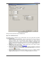
In the appropriate window sections set the file columns delimiter’s type (Comma, Space,
Tab, Semicolon or Other delimiters) and decimal delimiter for the coordinates values in the
file (Point only, Point or comma).
© 2011
38
Aerial triangulation
2011
Template settings for imported file
The text file (shown in fig. above) contains 9 columns from which only 7 (Name, X, Y, Z,
StdDevX, StdDevY, StdDevZ) are suitable for import; CODE, TYPE columns type are
excluded from the import and marked by “*” symbol in the template. Data import will begin
from the second row, because the first row represents the fields header. The field separator
is a comma, the decimal separator - point.
The button
is used to return to template by default (Name X Y Z).
After setting template for the imported file, define the action in case of identical names of the
imported GCP's and names of existing points in the list on the GCP's list tab of Triangulation
points window.
Recalculate the coordinate system if it necessary. To do this, specify the source and the
output coordinate system in the corresponding sections of the window. Push the OK button.
The imported data will be added to the end of the GCP's list on the GCP’s list tab of the
Triangulation points window.
4.2.1.1 Export of GCP list
39
RACURS Co., Ul. Yaroslavskaya, 13-A, office 15, 129366, Moscow, Russia
PHOTOMOD 5.21
Push the
button on the GCP's list tab of the Triangulation points window to export the
GCP's catalogue. Export GCP catalogue window opens for specifying file name of the csv
or txt formats.
GC points will be exported to text file of the following format:
NAME, X, Y, Z, CODE, TYPE, STDDEVX, STDDEVY, STDDEVZ
where NAME – GCP name,
X, Y, Z – coordinates values (“*“ is used for missing coordinate values),
CODE – point’s code,
TYPE – GC point’s type (control – GCP, check – check point),
STDDEVX, STDDEVY, STDDEVZ – RMS errors.
Comma is used as fields’ delimiter, and full stop as a decimal separator. The first line
contains fields’ headings.
Example of GCP catalogue export to text file
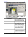
4.2.2 GCP measurement
After GCPs coordinates input you should recognize and measure ground control points on
images. GCP measurement is performed in Points measurement module.
For measurement and editing of GCP in Points measurement module, it is recommended to
use the All triangulation points tab, since the list shows measurement data, you can sort it
to find unmeasured points, etc. See also the chapter Triangulation points window.
Selecting of ground control point for measurement
Select GC point in the list of Triangulation points window and click the button
Show
point on images (duplicated by double click on selected point). At that if the orientation has
been already performed in geodetic coordinate system (e.g. by projection centers and after
measuring of 2-3 ground control points), all images which may contain selected point are
opened. The marker on the images is located in place of supposed measurement, i.e. the
system performs automatic marker positioning to current point neighborhood.
Otherwise (if there is no orientation performed), select and open needed images for new GC
point measurement by clicking the button
Add images in the Points measurement
window. See also a description of Main window of Points measurement module.
© 2011
40
Aerial triangulation
2011
GCP measurement without correlator
GCP measurement
General workflow of GCP measurement in Points measurement module is the following:
Select GC point you want to measure in the list.
Select images containing this point in the Points measurement window (if the point
is located in overlap zone).
Measure the point by one of the following ways:
– measurement without correlator. Use it if the point is located on the ground and is
well-recognizable on all images. Show by the marker its precise location on images.
Push the button
Add or move point measurements to marker positions on all
images in main toolbar of the Points measurement window.
– measurement and transfer using correlator. Use it if the point is not wellrecognizable on all images. In this case measure the point on one image using the
button
Move/add measurement into marker position in toolbar of image
window (see also the chapter Windows of opened images). Specify this image as left
–
. Then transfer the point measured on the left image on other images using
correlator by clicking the buttons
or
on the main toolbar of the Points
measurement window, keeping under control correlation coefficient (recommended
coefficient value is 0.90 – 0.95).
– measurement in stereo mode. Use it if the point is located above the ground (on
high object) and is not shown on all images. See the chapter Points measurement in
stereomode.
When the point has been measured, information about its measurement appears in
the list on the All triangulation points tab in Triangulation points window.
GC point transfer
Select measured GC point in the list (by double click)
41
RACURS Co., Ul. Yaroslavskaya, 13-A, office 15, 129366, Moscow, Russia
PHOTOMOD 5.21
Show by the marker a new location for the selected GC point
Transfer the point to a new location using the button
measurements to marker positions on all images.
Add or move point
GC point deletion
GC point measurement deletion. After deleting GC point measurement from images
using the button
, only the point measurement is removed, the point with its
coordinates remains in the list.
Entire GC point deletion. When deleting GC point measurement from the list using
the button
, the point is removed entirely from the system (measurement is
removed from images, the point is removed from the list along with its coordinates).
Search for a point in the list
To search for a point in the list click the button
. In the opened Find window input GC
point name (number) into Find field, and after that the appropriate entry will be selected in
the points list.
Moreover, you can acquire GC points coordinates from scanned and georeferenced raster
map, vector map or DEM for the same territory, which was a subject of airborne or space
survey. More details about raster map georeference see in the chapter Raster map
georeference, about obtaining of GCP coordinates from raster and vector maps – in the
chapter Adding points from a raster map and Adding points from a vector map.
Measuring control point on map
The program provides the function for obtaining the coordinate of control points from the
georeferenced base (for example, raster and vector map or DEM, covering the same area as
the project images) and measuring on the project images. See chapter Measuring control
point on map.
4.2.3 Measuring control point on map
If external data, covering the same area as project images, is present then it is possible to
use it as base for obtaining the control points coordinates and measuring it on the project
images.
The general workflow for measuring control point is following:
1.
2.
3.
4.
Loading of georeferenced base (map).
Search selected terrain point of map on the project images.
Adding/measuring of the control point on the project images.
Editing of control point.
4.2.3.1 Preparation and loading of georeferenced data
Do the following beforehand to use a georeferenced base image (map):
1. Prepare the input data. In the Windows file system, define the folder for location the
raster map - raster file format (TIFF, JPEG, BMP, IMG, PNG, NTF, GIF, PIX, JP2,
DEM) and georeferencing file with the same name (see also chapter Georeferencing
raster map). Pre-import the external vector data and DEMs into the files of the
PHOTOMOD internal format (x-data and x-dem, respectively) and save them in the
© 2011
42
Aerial triangulation
2011
folder of active profile. See the description of import vector data and DEM in the
Project processing User Manual.
2. Open the project.
3. Open the AT module.
4. Push the
button in the main toolbar of the Aerial triangulation module. The Map
window opens. All loaded data into the 2D window are displayed in working area of
the Map window. Push the
button to display the layer list and managing layer.
5. Load the georeferenced base (map):
Loading of
georeferenced data
Loading of raster map
Loading of vectors
Loading of DEM
Loading of web-map
Actions
Load georeferenced images button. The Loading images
Push the
window opens. Select the raster map file and push the Open button. The
Load georeferenced images window opens. If necessary choose
coordinate system transformation corresponding to the project coordinate
system. If the raster map contains background on the edges, then select
transparent background for such areas. Push the OK button. The new raster layer
appears in the layer manager and the loaded raster map displays in the
working area of the Map window.
Load vectors button. The Open window opens. Select the
Push the
vector file in the resources of active profile, convert, if necessary, the
coordinate system and push the Open button. The new vector layer
appears in the layer manager and the loaded vector data displays in the
working area of the Map window.
Load DEM button. The Open window opens. Select the DEM
Push the
file in the resources of active profile and push the Open button. The new
DEM layer appears in the layer manager and the loaded DEM displays in
the working area of the Map window.
Load web-map button. The Load web-map window opens.
Push the
Select the WMS data source in the Source list. Define the working area to
load web-map. In the Reproject panel define the coordinate system for
loaded web-map: Auto (reproject into project working coordinate system),
None (use coordinate system of the web-service) or Reproject into
coordinate system.
4.2.3.2 Searching corresponding GCPs on images
Before the adding / measuring of GCPs, select the visual ground sign on the map and set the
marker in this place, and then define the corresponding terrain point on the project images.
Searching of the corresponding terrain point on the images is performed as follows:
The presence of measured
GCPs in the project and / or
the presence and use of the
exterior orientation data
The project lacks for measured
GCP and Exterior orientation
data
The project already has the
measured GCP (at least 2
points) and / or the external
orientation data were used for
block layout creation
43
Actions
In the AT module, select and open the project images containing
button. Next, manually
the selected terrain point using the
define this terrain point on the opened images of the project using a
marker.
Use the synchronization tools to search the terrain point on the
project images:
Synchronize marker button in the Map
Push the
window to automatic search the corresponding terrain point
RACURS Co., Ul. Yaroslavskaya, 13-A, office 15, 129366, Moscow, Russia
PHOTOMOD 5.21
on the images, opened in the AT module. If necessary,
specify the location of the marker on the images.
Synchronize marker (with images
Push the
selection) button in the Map window to search the
corresponding terrain point on the all project images. All
images, in which the corresponding point is found, are
automatically opened in the AT module. If necessary,
specify the marker location on the images.
Note: Also provides for the reverse synchronization - searching the
terrain point of image on the map. To do this, set the marker on the
some terrain point on the image (in the active window); next, push
the
Find on map button of the main window in the AT module.
4.2.3.3 Adding to list and measuring GCP on project images
Add/measure the GCP after the selecting of the terrain point. The program provides the
following options for adding/measuring GC point:
Adding GCP without correlation.
Adding GCP with correlation. The presence of the measured points in the project or
the exterior orientation data with building of the block layout from this data is
necessary for using the correlation for adding GCP. In addition, an option is provided
to use DEM for obtaining the value of Z-coordinates of the point.
Adding GCP without correlation
Perform the following actions for quick adding of GCP without correlator:
1. Make active the Maps layer.
2. Set the correspondence between the terrain points on the map and on the images
using the marker (see chapter Searching of the corresponding GCPs on the
images).
3. Push the
button in the Map window. New GC point displays on the images and
appears in the in the triangulation points list of the AT module. If necessary, edit the
coordinate values or change the type of point (ground control point, check point) on
the GCP list tab (see chapter Triangulation points window ).
Adding GCP with correlation
Perform the following actions to add the GCP using correlator:
1. Make active the layer of raster map. If the DEM is available, load it into the Map
window.
2. Select the terrain point, using the marker, on the raster map. Push the
Synchronize marker (with images selection) button in the Map window for
automatic opening of the project images, containing this terrain point, in the AT
module.
3. Push the
Open tool panel for adding GCPs from map button in the Map
window. The Add GCPs from map window opens. The window is modal, i.e. work in
© 2011
44
Aerial triangulation
2011
the Map window and in the AT module is possible when the window is open.
4. Specify the active layer of the raster map in the Raster layer for correlation field.
Specify the DEM layer (if is available) in the DEM layer for obtaining Z field. If
necessary, refresh the layer list using the
5. Edit the correlator parameters.
Correlator parameters
GCD
Search area
button.
Purpose
Set the Auto check box for automatic definition of
GCD or specify the GCDs value manually.
Specify the search area of the corresponding
point on the image in meters (100 by default)
Correlation mask halfsize
Specify the size of correlation mask on the X and
Y axes in pixels (12 by default).
Contrast point search area
Set the check box and define the value of search
area in meters (10 by default), in which the
searching of maximum contrast point will be
performed. The parameter can be useful for
images with the increased percentage of the
continuous-tone areas. It is recommended to set
the 0 value during the measuring of points in
areas of low contrast (for example, when the
maximum contrast corresponds to the forest
vegetation; the chances are high that the
correlation will be with errors within this area).
Correlation threshold
Determine the minimum acceptable value of
correlation coefficient for measuring of points (0.8
by default) based on the images quality. The
point with the correlation threshold, below the set
value, will not be considered when adding (The
«Bad point» message is shown).
6. Add the GCP using correlator. The window provides the following tools to do this:
45
RACURS Co., Ul. Yaroslavskaya, 13-A, office 15, 129366, Moscow, Russia
PHOTOMOD 5.21
Button
Correlate and move marker
Add point with correlation on the active
image
Add point with correlation on all images
Add point without correlation
Purpose
This feature allows searching the corresponding
point on the active images using the correlator
and moving the marker to the obtained point. If
the correlation will be satisfactory, the marker
falls into the obtained point. Otherwise, the «Bad
point» message is shown. Select another terrain
point on raster map.
This feature is used to adding / measuring of
GCP on the image in the active window. The
search of corresponding point is performed when
the button is pushed. If the correlation will be
satisfactory, the marker falls into the obtained
point and the Edit point window (see description
below). Otherwise, the «Bad point» message is
shown. Select another terrain point on raster
map.
This feature is used to adding / measuring of
GCP on all opened images in the AT module.
The search of corresponding point is performed
on all images when the button is pushed. If the
correlation will be satisfactory, the marker falls
into the obtained point and the Edit point window
(see description below). Otherwise, the «Bad
point» message is shown. Select another terrain
point on raster map.
This feature allows quick adding the new GCP
without correlator into the location of marker.
The Edit point window is used to view/edit coordinates of selected terrain point, as well
as estimate the correlation coefficient and select such images, on which the new point
will be measured.
© 2011
46
Aerial triangulation
2011
Enter the name of new GCP in the Name entry field. Define coordinates, which will be
added. The value of Z-coordinate is displayed if the DEM has been used. The list below,
estimate the correlation coefficient and select the images, on which the new GCP will be
measured. The following options are provided for adding / measuring of GCP:
Button
Add point with measurements
Add point without measurements
Replace GCP with measurements
Replace GCP coordinates
Replace measurements only
Purpose
This button allows adding new GCP with
coordinates in the Triangulation point list and
measuring it on the selected images.
This button allows adding new GCP with
coordinates in the triangulation point list without
measurement on the selected images.
This button allows replacing coordinates of
selected point in the triangulation points list and
re-measuring it on the images.
This button allows replacing only coordinates of
selected point in the triangulation point list without
editing of measurement.
This button allows re-measuring point, selected in
the triangulation point list, on the images without
editing of coordinates.
7. If necessary, edit the GCP in the AT module after its adding/measuring.
4.2.3.4 Map window
Main purpose of the Map window is the georeferenced data loading (raster and vector maps,
DEM) to use for adding and measuring of GCP on the project images.
The Map window opens using the
47
button of main toolbar of AT module.
RACURS Co., Ul. Yaroslavskaya, 13-A, office 15, 129366, Moscow, Russia
PHOTOMOD 5.21
Map window
All data, opened in the 2D window, are displayed in the working area of Map window. The
Map and 2D windows are fully synchronized by content. On the right is the manager layer
window for managing these data and a navigation window for quickly moving to necessary
data.
The top part of window contains the following tools:
– Loading of raster map – Window allows to select raster format file in the
Windows file system (TIFF, JPEG, BMP, IMG, PNG, NTF, GIF, PIX, JP2, DEM), see
chapter Preparation and loading of georeferenced data.
– Loading of DEM – Window allows to select the DEM in the resources of active
profile for obtaining Z-coordinate from it (see chapter Preparation and loading of
georeferenced data).
– Loading of vectors – Window allows to select the vector file in the resources of
active profile (see chapter Preparation and loading of georeferenced data).
– Loading of web-map – Window allows to select source of geospatial data of
WMS standard and load web-map, covering selected area (see chapter Preparation
and loading of georeferenced data).
– Search the marker position in the windows of opened images. Searching of
area, specified on map using marker, on the images in the opened windows of AT
module. The use of the tool to search points is possible if the projects images already
© 2011
48
Aerial triangulation
2011
have measured GCPs (at least 2) or block layout is built by exterior orientation data
(see chapter Searching of the corresponding GCPs on the images).
– Search on the project images – the searching of terrain point on all images is
performed. The use of the tool to search points is possible if the projects images
already have measured GCPs (at least 2) or block layout is built by exterior
orientation data (see chapter Searching of the corresponding GCPs on the images).
– Add GCP without correlation – allows quick adding and measuring GCP on the
selected images (i.e. allows transferring GCP with coordinates from map to the
marker position on the selected images). The added point displays on the images and
appears in the list of triangulation points of the AT module. If necessary, edit the
added point. For example, change the name or type (GCP, check point) (see chapter
Adding to list and measuring of GCP on the project images).
– Panel of adding GCP – allows to add and measure GCPs. Window allows using
the correlation algorithm for searching of corresponding point on the images, as well
as the DEM for obtaining Z-coordinate (see chapter Adding to list and measuring of
GCP on the project images).
– marker mode == mouse (duplicated by the F4 button).
– center on marker (duplicated by the F7 button) – image in the Map window is
moved in such a way that the marker falls in the center of the window.
– fixed marker mode (duplicated by the F6 button) – in this case, the marker is
always in the middle of the screen and moving the mouse results in a corresponding
movement of the image.
– service panels – allows to open/close the service panels to the right of the
working area (the layer manager and the navigation window).
– navigation window – allows to open/close the navigation window.
– scrollbars – allows to show/hide the scrollbars.
– zoom in.
– zoom out.
– zoom to fit (duplicated by the Alt-Enter shortcut)
– show in the 1:1 scale (duplicated by the Alt-1 shortcut)
– field that displays the scale of image in the window. The scale can
be set using the slider.
Moving the image in the Map window is performed using the mouse with the pressed Alt
button (panning mode).
The bottom part of the Map window contains the sliders for adjusting brightness, contrast
and gamma-correction of images.
The status bar at the bottom of the window displays the coordinates of the marker on the
georeferenced map.
4.2.3.5 Raster map georeference
For ground control point’s coordinates acquisition it is helpful to use scanned and
georeferenced topographic map for the same terrain, which was surveyed for acquisition of
aerial and space images processed in PHOTOMOD project. Scanned map could be
georeferenced using ground control points coordinates in PHOTOMOD Core.
49
RACURS Co., Ul. Yaroslavskaya, 13-A, office 15, 129366, Moscow, Russia
PHOTOMOD 5.21
For raster image georeference use menu command Service | Image georeferencing, that
opens the window Raster georeference. This window allows to open raster map and
reference it using known GCP coordinates.
Map georeferencing window
If the file with scanned topographic map is stored in the same folder as georeference file in
MapInfo TAB format (georeference file name should be the same as map file name), the list
of georeference points and their coordinates is opened in Raster georeference window. In
this list Xg, Yg – geodetic coordinates, Xp, Yp – pixel coordinates, Name – point name.
To visualize a point in raster window (to place marker in point’s pixel coordinates) click the
cell in the Name column and in the raw of the point’s number in the table.
Upper menu buttons are intended for the following operations:
- load raster map – opens dialogue of raster file selection in main raster formats
(duplicated by Ctrl-O shortcut)
- load reference map – opens dialogue for selection of raster file with map (in main
raster formats)
- load vector map – opens dialogue of vector file selection in DXF, DGN or Shape
format.
- load XYZ points from file – opens dialogue of GCP coordinates file selection (in TXT
format) and opens it as a table below the map window. Point’s coordinates could be loaded
replacing opened coordinates or in addition to them, after an appropriate warning.
- save – saves georeference file in MapInfo TAB format, at that file name is the same as
map file name but with TAB extension.
,
,
,
- zoom management, duplicated by hot keys usual for PHOTOMOD
system - /, Alt-1, *, Alt-Enter respectively
- shows zoom scale in raster map window
© 2011
50
Aerial triangulation
2011
- map displaying in grayscale or color mode
For more convenient work the map could be rotated in following ways:
- without
- turn at 90 degrees,
- turn at 180 degrees and
- turn at 270
rotation,
degrees. At that raster file is not changed and the rotation is executed “on the fly“.
- clear – deletes all points (list cleanup)
- add point – measures new point coordinates on the map and adds them to the end of
list. At that marker pixel coordinates are assigned to point and 0 value is assigned to
geodetic coordinates (you can enter them manually to appropriate cell by replacing text
selected by mouse in this cell)
- delete point – deletes a point selected in the list, duplicated by hot keys Ctrl-Del
- re-measure – replaces pixel coordinates of selected point. At that current pixel
coordinates of marker are assigned to the point and saved to the list
- auto-place – places marker to coordinates of point, selected in the list
- copy coordinates to clipboard – copies coordinates of selected point to clipboard.
Coordinates are in the following format "Xp Yp Xg Yg"
- paste coordinates from clipboard – pastes selected point coordinates from the
clipboard in the following possible formats: "Xg Yg", "Xg Yg Zg", "Xp Yp Xg Yg", "Xp Yp Zp
Xg Yg Zg", where Zp equals 0.
- select color – opens standard OS Windows palette to choose GC point’s symbol color
on the map.
For map georeferencing you should recognize points with known geodetic coordinates on the
map. Map could be referenced using only one point (in that case it is considered that
measurement unit is 1 pixel and axes coincide. If there are two points, the map will be scaled
and rotated, in case of three points affine transformation will be applied), but for accuracy
control you should measure at least 4 points. To measure point put marker on point’s place
on the map and push the button
(Add point). After that, point’s name and pixel
coordinates will be added to the list below the map. Input geodetic coordinates of the point to
appropriate cells manually. When fifth point is measured, coordinates measurement errors
EХ and EУ will be automatically calculated and saved to the last column of the list below the
map.
To edit coordinate value in table cell you should select the cell and press F2. To end editing
and save coordinate press Enter, to exit from editing without coordinate save press Esc.
When georeference is completed push the button
MapInfo format.
(save) to save georeference file in
You can use georeferenced raster map to add points on project images. See also the
chapter Adding points from a raster map.
4.3 Automatic tie points measurement
PHOTOMOD system provides performing of tie points measurement and relative orientation
in automatic mode. Automatic mode uses correlation algorithm for tie points search and
measurement.
51
RACURS Co., Ul. Yaroslavskaya, 13-A, office 15, 129366, Moscow, Russia
PHOTOMOD 5.21
Automatic mode of tie points measurement provides ample opportunities for relative
orientation of images block – choice of optimal parameters to measure, adding and filtering
of tie points using different criteria allows to reach required accuracy and substantially reduce
time of project processing on relative orientation stage. Repeated ties measurements in
automatic mode along with correction of parameters values, as well as manual mode using
for measurements refining and errors handling guarantees excellent results on block
adjustment stage.
4.3.1 Working order and terms
Automatic tie points measurement procedure requires the following data:
interior orientation of all images, that will be used in automatic tie points
measurement (see the chapter Interior orientation)
Note: It is highly recommended to perform interior orientation, since otherwise most
filtering parameters will be not applied during automatic ties measurement, and thus
the quality of relative orientation in automatic mode is not guaranteed.
Block layout
Note: The sufficient condition for start of tie points measurement in automatic mode is
creating of initial (“rough”) block layout, considering, for example, images overlap data
and/or manual matching data. Nevertheless, the more data is considered for block
layout creation, the more accurate is block scheme, and correspondingly, the better
results of automatic ties measurement.
Working order on ties measurement in automatic mode includes the following operations:
Create block layout considering available data (see the chapter Block layout).
Set up parameters of points measuring, transfer, filtering, and start automatic ties
measurement (see the chapter Performing of automatic tie points measurement).
Estimate relative orientation accuracy to detect tie measurement errors (see the
chapter Relative orientation report).
Note: For relative orientation accuracy analysis you can also perform block adjustment
and estimate errors of ties measurement on the Images tab (see the “Block adjustment”
User Guide).
Remove ties measurement errors manually in the Points measurement module (see
the chapter Manual measuring of triangulation points) or select other filtering
parameters (e.g., by setting up more rigid acceptable error thresholds) and start
automatic measurement once more.
Refresh the block layout considering measured ties. Change parameters settings if
necessary, and re-start automatic ties measurement for further collecting of tie points
measurements. Repeat steps 3-4.
4.3.2 Performing of automatic tie points measurement
To perform automatic tie points measurement do the following:
–
–
–
Use the parameter presets or specify manually all the basic actions / parameters for
searching, measuring, and rejection of points in the Automatic tie point measurement
window, as well as additional parameters to estimate the basic parameters and a more
"fine tuning" in the Tie point measurement parameters window;
launch automatic points measurement operation (by clicking the Start button in
Automatic tie point measurement window)
open Relative orientation report used to browse relative orientation results and edit
measurements.
© 2011
52
Aerial triangulation
2011
4.3.2.1 Automatic tie point measurement window
To perform tie points measurement in automatic mode click the
button in the
Triangulation toolbar or choose Orientation | Automatic tie point measurement. The
appropriate window opens.
Note: The Automatic tie point measurement window allows using the parameter
presets, set-up optimally, for aerial and UAV imagery or selecting manually the main
and additional parameters for automatic searching, measuring and rejection of points.
Automatic tie points measurement window
The Automatic tie point measurement window contains the following interface elements:
Toolbar for selection of images, opening the additional windows, saving and loading
presets.
The list of project images for selection of images for which automatic tie point
measurement is to be performed.
Tasks panel allows to specify actions which will be performed at start of automatic tie
points measurement operation
Parameters panel allows to specify a set of parameters, used during search,
measurement, adding and filtering of points
The More button is used for setup additional parameters of tie points measurement.
See the chapter Additional measurement parameters
The Start button used for launch of tie points measurement procedure in automatic
mode and performing of relative orientation. To view the results of relative orientation
operation open Relative orientation report.
53
RACURS Co., Ul. Yaroslavskaya, 13-A, office 15, 129366, Moscow, Russia
PHOTOMOD 5.21
The Distributed processing button is used for automatic tie point measurement in
the distributed processing mode. Opens the Distributed measurement of tie points
window to define number of tasks.
The selection of images is performed in different ways. Set the tick opposite the image name
to select a single image in the list. Set the tick opposite the image strip to select all images of
the single stripe in the list. In addition, the toolbar contains the following additional tools for
images selection:
- allows to select all images in the list;
- allows to unselect all images in the list;
- allows to invert image selection;
- allows to select highlighted images;
- allows to unselect highlighted images.
- allows to select image from the list, selected in the block scheme;
- allows to select the images in the block scheme, which were selected from the
images list
To highlight image in the list, click its name in the list. Use the Ctrl and Shift shortcut to
highlight several images.
The following buttons are provided to open the additional windows in the toolbar:
- is used for opening the Block layout window;
- is used for opening the Report on relative orientation window;
- is used for opening the Tie points list window;
- is used for opening the AT module displaying images checked in the list (given
that there are not more than 6 images checked).
The following buttons are provided for saving and loading presets:
- push the appropriate button to load the saved before preset with *.x-ini
extension. The drop-down menu button brings up a menu with the following items:
Load settings from file – open the Load settings window to load the presets with
*.x-ini extension from Windows file system;
Reset setting to defaults – allows to use the presets by default;
UAV – allows to load the preset, optimally chosen for UAV images;
Standard – allows to load the presets, optimally chosen for aerial images.
- push the appropriate button to save the presets with *.x-ini extension.
Tasks panel contains two groups of parameters. The first group allows to specify the
following operations:
Measure tie points in stereopairs – allows to search and measure tie points on
adjacent images of stereopairs.
Transfer tie points – allows to transfer measured points on adjacent stereopairs (i.e.
to transfer points, located in triple overlap zone, to adjacent models).
Filter tie points by relative orientation – allows to filter points, which have
measurements exceeding preset acceptable errors threshold. Points check for
filtering is performed sequentially by types of errors – first for exceeding of correlation
threshold, then for maximal value of vertical parallax, and finally for errors in triplets, if
© 2011
54
Aerial triangulation
2011
the appropriate option is selected. At that, check for exceeding of correlation
threshold is performed only for new points (if there are already measured points). If
you need to check all measured points for exceeding of correlation threshold (usually
on check completion), you should select an additional option Delete points with
correlation below threshold on Rejection tab in Additional measurement
parameters window.
Each operation (measurement, transfer and filtering) is setup individually for measurements
inside strip (when the Inside strips checkbox is selected) and between strips (when the
Between strips checkbox is selected).
The second group of parameters in the Tasks panel contains the following options:
Filter tie points by adjustment results – allows performing automatic block
adjustment with specified parameters and using its results for points filtering. Such a
filtering is useful, for example, if there are blunders on images between strips.
Filtering is performed using values of acceptable errors preset in Parameters
window, opened by clicking the Set up button. Specify the adjustment method on the
Adjustment tab and setup values of acceptable errors on the Report tab. If there are
no GCP, you should use a free model as adjustment method, in this case it is
recommended to setup the basis value as precise as possible. More details about
Parameters window see in Block adjustment User Guide.
Report on relative orientation on completion – opens the Report window used for
viewing and editing of tie points measurements right after performing of automatic
relative orientation. See the chapter Relative orientation report.
Parameters panel contains the following parameters:
Points per stereopair – allows to set a number of points measured on each
stereopair (the resulting amount of measured points on stereopair could be both more
than this number (due to their transfer from adjacent stereopairs), and less than it due
to the further rejection). Default number is 30 points inside strips, and 10 points
between strips. Minimal number of points needed for control of residual vertical
parallax – 6.
Depending on the options on the Miscellaneous tab, the Points per stereopair
parameter specifies either number of points to be added at each stereo pair in one
session, (if the Points to add per session option is selected), or the target number
of points, which must be measured at each stereo pair (if the Target number of
points on a stereopair option is selected). I.e., for example, if there are 10 points
already on a stereopair, and the Points per stereopair parameter is 30, there will be
30 points added in former case and 20 in latter case.
Correlation threshold - the minimal acceptable value of correlation coefficient for tie
point to be accepted during automatic search. Recommended value is 0.9 – 0.95. In
contrast to all other rejection criteria this parameter influences on point measurement
and transfer process directly. Check for exceeding of correlation threshold is
performed only for new points (if there are already measured points). To check all
measured points for exceeding of correlation threshold (usually, at final stage) you
should select additional option Delete points with correlation below threshold on
the Rejection tab in Additional measurement parameters window.
Maximum vertical parallax (in pixels or millimeters) - threshold value for rejection
executed after points measuring/transfer. On each step of rejection process, the
program searches for the point with maximal Y-parallax on the stereopair and rejects
it. After that, it makes relative orientation once more and the iteration is executed until
maximal Y-parallax exceeds the parameter specified here, or until 6 points or less
remain on stereopair. Recommended value is a pixel size.
55
RACURS Co., Ul. Yaroslavskaya, 13-A, office 15, 129366, Moscow, Russia
PHOTOMOD 5.21
Maximum error in triplets in XY-plane and by Z (in pixels, millimeters or meters)
- threshold discrepancy of points measurements on adjacent stereopairs in triple
overlapping zone of adjacent images in a strip. Use the following formula to calculate
values of acceptable errors in triplets:
Emax 2 Emean , where E mean - acceptable mean error
Mean triplet errors in XY plane should not be greater than half of pixel size multiplied
by √ 2, error by Z equals the mean triplet errors value in XY plane multiplied by the
ratio of focal length (f) to survey basis (b) (in image scale). See below:
xy
E mean
2 0.5 pxl
z
E mean
f
xy
E mean
b
Measure points by zones - allows to use a method of sequential measurement by
zones of overlap area. Use Zones section on the Miscellaneous tab in Tie point
measurement parameters window to adjust parameters of such zones. If the option
is off, points are measured on the entire stereopair area uniformly.
Filter points by zones - allows using zones on stereopair for filtering of measured tie
points. The operation provides filtering the worst (by parallax) points on stereopair,
passing zone by zone one after another. So the worst point on stereopair is found
and deleted first, then the worst one in the next zone and so on. Uniformity of point’s
distribution on stereopair is also verified in such a way.
4.3.2.2 Additional measurement parameters
Use the Tie point measurement parameters window to specify the main parameters of tie
point measurement and "fine" setting. This window opens using the More button in the
Automatic tie point measurement window.
© 2011
56
Aerial triangulation
2011
Tie point measurement parameters window
The window contains following tabs:
Search for points
Correlator
Rejection
Miscellaneous
The window consists of the following tabs:
Search for points – contains the following settings:
Search area (pix) - searching area for areal correlator. It is setup depending on block
layout accuracy. Typical values are from 10% to 30% of image size. Default value is 1000
pixels. Actual search area may be determined in the Points measurement module (see
chapter Measuring the corresponding point search area); if actual value is larger than
1000 pixels, increase this parameter according to the measurement results.
Contrast point search area (pix) - default value is 100. The parameter is used for tie
points search in areas of maximal contrasts (images with clear object’s features). In some
cases it is advisable to measure points in areas with low contrast (for example, when
maximal contrast corresponds to woods areas, where correlator errors have high
probability). The parameter value may be reduced there up to 10 for example. In this
case you should setup 0 value in this field.
Tries per point - number of tries to calculate correlation for each point out of the amount
set by the Points per stereopair setting on Parameters panel of the main window (100
– by default). Maximal amount of tries to found a point with correlation coefficient not less
than threshold specified is a multiplication of this parameter by the Points per stereopair
value.
Multipass points search – allows making several passes for point measurement and
filtering using different algorithms in case of insufficient quality of the block layout, when
57
RACURS Co., Ul. Yaroslavskaya, 13-A, office 15, 129366, Moscow, Russia
PHOTOMOD 5.21
real relative rotation of images differs from what is present in block layout. Usually this
parameter should be used for UAV images.
Search the whole images area – allows defining the stereopair for points searching: the
neighboring images in the strips or other stereopairs (i.e., the non-neighboring pairs in
the strip and inter-strip stereopairs).
Correlator – the tab is intended for setting areal correlator parameters:
Correlation matrix half size – size of correlation matrix by X and Y axes (measured in
pixels).
Autocorrelation control – I.e., the bigger the value, the less the reliability of points that
will be collected by correlator with this point as initial one.
Do not use image border area – is used for setting service information area with
specified width near the image edge should not be used for correlator work. Service area
width (2% of image width and height by default) should not be less than on the image;
otherwise a big amount of wrong points would be measured in image service areas.
Image blur – slider, which allows taking into account the images quality.
The Bands section contains three parts: Grayscale (by default), RGB and Green. The
RGB option can be activated for tie point calculation on the color images. It can enhance
measurement accuracy, but increase the work time of automatic calculation. Activation of
the Green option is recommended for low quality images from UAV
Correlation parameters
Rejection tab is used to setup point’s filtration parameters:
© 2011
58
Aerial triangulation
2011
Tie points filtration parameters
59
Preliminary filtering with detection of trusted points group – is used for preliminary
filtering of blunders, which are do not allowing to compute relative orientation angles
correctly (see the trusted points group parameters on the Miscellaneous tab).
Delete all tie points, if after filtering number of them left is less then – when the
option is active, the system deletes all measured points on the stereopair, if the relative
orientation cannot be calculated correctly. It is likely that some (or all) points on the
stereopair, in this situation, are erroneous, and removal of them would improve the
overall quality of the block orientation.
Delete points with correlation below threshold – when there are tie points measured
automatically using correlator, you can filter these points after specifying the threshold
value in the Automatic tie point measurement window. It is suitable to use the option for
recurrent or final point’s filtration, since the filtering covers all measured points, not only
new ones, added during recurrent start of automatic tie points measurement operation.
Delete single points – allows to filter and delete points measured on single images.
Delete measurements on non-adjacent images – allows to filter potentially erroneous
points, measured on non-adjacent images inside a strip.
Delete points surplus – make the system delete points above the quantity, specified by
the Points per stereopair parameter in the Automatic tie point measurement window,
sorted by the Y-parallax in descending order. The tie points are evenly deleted, if the
Filter points by zones option is checked. It is recommended to use after the initial tie
points measurement for UAV project.
X-parallax clipping (%) – number of points with minimal and maximal x-parallax
(relatively to total amount of points) which will be deleted. You should apply this rejection
method if erroneous points are dispersed clearly along stereopair basis (if, for example, a
RACURS Co., Ul. Yaroslavskaya, 13-A, office 15, 129366, Moscow, Russia
PHOTOMOD 5.21
highway with bright marking goes in parallel to survey basis and correlator puts points on
marking line elements, which do not correspond with each other).
The Miscellaneous tab contains some additional settings which are not needed to change
frequently.
Additional parameters
The Search for points section contains the following parameters:
Number automatically measured points starting with – is used for automatic
numbering of measured tie points starting with number, specified in the entry field. It
allows to distinguish these points from the ones already measured on the project
images. Regardless of the set value, the system does not generate points with
duplicate numbers. If the point with some number already exists, then this number
will be skipped when creating of new points.
Minimum distance between points (pix) – minimal distance in pixels between
points measured on the image (5 – by default). It is recommended to increase the
value of this parameter, when the problems with block adjustment.
Fixed search sequence – If this option is checked, the sequence of images areas
searched for points is fixed. Otherwise, the system tries different random image spots
each run. The former case (fixed order) may be useful, for example, for performance
testing; the latter (random order) is best for everyday practice.
Use automatic block layout results – allows to use the block layout results,
automatically created for UAV images.
«Points per stereopair» option button specifies either number of points to be
added at each stereo pair in one session, (if the Points to add per session option is
selected), or the target number of points, which must be measured at each stereo
pair (if the Target number of points on a stereopair option is selected). I.e., for
© 2011
60
Aerial triangulation
2011
example, if there are 10 points already on a stereopair, and the Points per
stereopair parameter is 30, there will be 30 points added in former case and 20 in
latter case.
The next section defines so-called "trusted group" settings. The concept of trusted group is
used for rejecting points as described below (see Preliminary filtering with detection of
trusted points group parameter on the Rejection tab). A group of points is considered
trusted, is it complies with the following two conditions:
1 condition: the distance between the point on the one image and the corresponding point on
another image no more than a specified the Maximum spread radius within trusted points
group parameter.
2 condition: number of points, satisfying the condition 1, no less than specified value in the
Minimum trusted points group size entry field.
If a trusted group has been found, it supposedly means that initial relative orientation has
been computed correctly and in this case, the point’s rejection can be applied by these data.
Otherwise, the rejection of points will not be executed, even if the Preliminary filtering with
detection of trusted points group parameter is checked on the Rejection tab.
The Maximum points to use filtering by trusted group parameter specifies the limitation
on the number of points to reject. It is recommended to set this value to 40-60 points. It is not
recommended to set more than 60 points.
The Stereopairs section contains the following parameters:
Create stereopairs based on exterior orientation data, from images, projection
centers of which are within range of – if this option is not checked, the "nearest
image" principle is implemented for composing stereopairs; if this option is checked,
the stereopairs will be composed from images, projection centers of which are
located at the distance no more than a specified value (in meters)
From different strips only – if this option is checked, the instrip stereopairs will not
be considered. Otherwise, all instrip stereopairs will be considered, including the
nonadjacent.
The Zones section is used for defining zone size on the stereopair, in which the automatic
search and tie points measurement is to be performed. The Relative orientation chapter
contains info about the recommended zones.
The Points transfer section – allows estimating the initial approximation, as well as turning
on the automatic transfer of manually measured GCPs and tie points along with automatic
measured points.
The Rejection by angle section is intended for setting the filtration parameters of measured
points from the images relative orientation.
In some cases, after the automatic tie point measurement, the images from the block can be
rotated. And images relative orientation can be calculated incorrectly because of erroneous
points. The probable rotate of images can be prevented. Turn on the filtering of measured tie
points by the values of the angle rotation. In this section the value of angles (in degrees) for
each of the elements of the stereo pair can be changed. Then tie points, which lead to
excess of threshold values of the angles after the recalculation of the images relative
orientation, would be filtered.
It is not recommended to use this method of rejection for blocks, in which the images can
actually be rotated to each other. In this case the correctly spaced tie points would be
removed.
Push the OK button for returning in the Automatic tie points measurement window after
setting the presets.
Push the Start button for starting the searching, measuring and rejecting of points in
automatic mode.
Open the Relative orientation report for viewing and editing results of the automatic tie point
measurement.
61
RACURS Co., Ul. Yaroslavskaya, 13-A, office 15, 129366, Moscow, Russia
PHOTOMOD 5.21
4.4 Manual measuring of triangulation points
PHOTOMOD system allows to perform tie points measurement in manual mode, to measure
ground control points, to edit erroneous measurements, acquired by automatic points
measurement. For these operations, the system offers Points measurement module, which
provides a wide range of possibilities for triangulation point’s measurements and performing
relative orientation.
4.4.1 Points measurement module
Points measurement module is used for triangulation points (ground control, check and tie)
measurement in manual mode. At that during tie point measurement, relative orientation
parameters are calculated automatically.
Points measurement module may be used on the following steps of project processing:
– input/measurement of ground control points (see the chapter Input and measuring of
ground control points);
– measurement of tie points on block images in full manual mode and relative orientation
perform;
– editing of tie points for correction of errors, appeared after measuring and performing of
relative orientation in automatic mode (see the chapter Automatic tie points measurement);
– editing of triangulation points for correction of errors, appeared on block adjustment
stage. See Block adjustment User Guide.
– tie points measurement for accuracy evaluation by Y-parallax after import of exterior
orientation parameters. See the chapter Import of exterior orientation parameters.
Relative orientation module is integration of two windows: main window Points
measurement and Triangulation points window. Main window of Points measurement
module shows selected images in separate windows and contains tools for operations of
triangulation points measurement. Triangulation points window is a list of all measured points
of images block with measurements data and contains tools for work with the list.
© 2011
62
Aerial triangulation
2011
Points measurement module – combination of two windows: Points measurement and
Triangulation points
Features of the Points measurement module
Work in both windows is synchronized. That means that during work in the module you will
face the following:
If you select a point on image by double click, this point will be automatically selected
in the list and в shown in opened images windows, if it is measured on these images
If you select a point in the list by single click, this point will be automatically shown in
opened images windows, if it is measured on these images
If you select a point in the list by double click (or by the button
Show point on
images), there are two cases possible:
o all images windows, where the point is measured are opened;
o all images windows, where the point is measured or could be measured (with
marker located in position of supposed measurement) are opened. See also
the
button description in the chapter Triangulation points window.
In example on figure below the point is already measured on 5 images, and one image is
opened where it could be measured.
63
RACURS Co., Ul. Yaroslavskaya, 13-A, office 15, 129366, Moscow, Russia
PHOTOMOD 5.21
View position of selected point in the list on image where it has been measured and on
image where it has not been measured
Start of Points measurement module
To open Points measurement module use the following menu commands of Orientation
menu item (duplicated by buttons of Triangulation toolbar):
Open selected images for measurement (duplicated by the button
) –
opens Points measurement module and windows with images selected in Block
editor or 2-D window
Open images containing marker (duplicated by the button
) – opens Points
measurement module and windows with all images, containing a position of
marker, placed in 2-D window
Open in-strip stereopair (duplicated by the button
) – opens Points
measurement module and two windows with images of stereopair selected inside
a strip. If you selected one image you will get opened its adjacent right image in
the strip by default, if there is no right image – left image will open
Open inter-strip stereopair (duplicated by the button
) – opens Points
measurement module and two windows with images of selected inter-strip
stereopair. If you selected one image, you will get opened its adjacent lower
image by default, if there is no lower image – upper image will open.
See also description of Main window of Points measurement module, and Triangulation
points window.
Relative orientation procedure
© 2011
64
Aerial triangulation
2011
After measuring of each new tie point relative orientation of images is performed
automatically (vertical parallax is calculated for measured points). To view relative orientation
results push the button
Report in the list window. The relative orientation report is
opened in read only mode and according to parameters, specified before in the Relative
orientation report settings window. See also the chapter Relative orientation report. You
can also open a report with relative orientation results only for opened images. Use for that
main toolbar button
of Points measurement module.
4.4.1.1 Main window of Points measurement module
Main window of Points measurement module is intended for displaying, measuring and
editing of triangulation points on opened images. Here you can measure points and change
point’s position on any image (re-measure it) manually or using correlator in mono or stereo
mode.
Main window of Points measurement module
The window contains main toolbar and windows of selected images; each of them displays
image and its name, and contains its own toolbar and status line.
Main toolbar buttons of Points measurement window are used generally for performing of
different operations for all opened images:
– zoom in image in all windows.
– zoom out image in all windows.
– show image in original size 1:1 in all windows.
– fit image to window in all windows.
– center image on marker in all windows.
– shift one image left (“scroll” images in opened windows to the left).
– shift one image right (“scroll” images in opened windows to the right).
– shift one image up (“scroll” up images in opened windows).
– shift one image down (“scroll” down images in opened windows).
65
RACURS Co., Ul. Yaroslavskaya, 13-A, office 15, 129366, Moscow, Russia
PHOTOMOD 5.21
– arrange windows – resize image windows left in the Points measurement window
after closing some of them (to “fill in” the background)
– add images in new windows – opens the Add images window used for images
selection
Adding images to the Points measurement module
You can select manually images to be added. Light green color indicates strips and images,
which contain selected tie point (in the list or on opened images). To automatic selection of
images that contain selected tie point click the button
automatically).
(Select images
– images transformations have effect on images displaying and on points
measurement using correlator in Points measurement module. This tool provides images
relative orientation (rotation and scaling) considering images location relatively to each other
and scales difference in block scheme or in block layout data. Click the button to select one
the following options in drop-down list:
No transform – shows images as is
Rotation by block scheme, 90 - multiple – allows to rotate images at angle, at
which images were rotated during block forming in 2D window. The rotation angle is
rounded to closest angle, divisible by 90
Rotation by block scheme, exact – allows to rotate images at angle, at which
images were rotated during block forming in 2D window
Block layout: rotation – allows to rotate images according to block scheme
Block layout: scale and rotation – allows to move images using rotation and scaling
according to block scheme
Block layout: projective transform – allows to rotate images using projective
transformation (exactly as in block scheme)
Image scale – allows to change basic scale of images for correlator. The same scale
will be used for images displaying in scale 1:1.
– update block layout automatically as points are added (off by default). Affects images
open in the module, i.e. only local block layout is recalculated.
– new stereo window – opens a stereo window for selected pair of images. Used for
points measuring in stereo mode. See also the chapter Points measurement in stereomode.
By default opens stereo image for the whole working area of Points measurement window
(i.e. instead of all opened images windows). If you hold down the Shift key while clicking the
button, stereowindow will open with size of two windows of images selected for displaying in
stereo mode. If you hold down the Ctrl key while clicking the button, stereowindow will open
with size of one window in position of the “left” image. Press Esc to close stereo window.
© 2011
66
Aerial triangulation
2011
– color/black-and-white images. Switch key for images displaying in color or black-andwhite mode.
– add a tie point with measurements on all images. Adds a tie point to marker position
on all opened images without correlation (you should position the point manually on all
images).
– add or move selected point measurements to marker position on all images without
correlation
– move point along tie error vector on all images. See also description of right panel
buttons.
– move point along error vector on GCP on all images. See also description of right
panel buttons.
– delete measurements of selected point on all images, where it is measured.
– delete filter. Opens the Delete point measurements window allowing to select criteria
of points filtering for deleting. Duplicated by menu command Orientation | Delete point
measurements. See description in chapter Point measurements deletion.
– synchronize markers on all images – searches for the same marker position on all
open images, as on the selected image. For synchronization you need block layout data. So
the more data used for block layout creation, the more precise positioning of marker. I.e. the
main point of synchronization is searching for the same place on other images and
positioning of marker there.
– open stereopair. Select “right” image for specified “left” one (use the button
in
toolbar of the image window) and two images of a stereopair will open in the Points
measurement window.
– correlate active image to “left” (duplicated by the Space key). Allows to measure a
new point on two images using correlator. For that you should set as a “left” one of images
using the
button in image window toolbar and show by marker the point’s position to be
measured. On another image it is enough to show approximate point’s position. This tool
opens the New point window. It shows point’s code, its default name that is editable using
any symbols. Below you can see images list – left and active image with correlation
coefficient of measured point. At that, if the correlation coefficient is not less than threshold
value specified in the Parameters of points measurement (
) window, the active image will
be automatically checked in the list. If the correlation coefficient is too low ("bad point"), the
image is marked in red. As a result, it is necessary to choose – either to add point on both
images, if the correlation coefficient is satisfactory or to add point on left image only, or click
Cancel to re-measure point.
67
RACURS Co., Ul. Yaroslavskaya, 13-A, office 15, 129366, Moscow, Russia
PHOTOMOD 5.21
– correlate all images to “left” (duplicated by Ctrl+Space shortcut). Allows to measure a
new point on all images using correlator. For that, you should set as a “left” one of images
using the
button in image window toolbar and show by marker the point’s position to be
measured. On another images it is enough to show approximate point’s position. You can
consider block layout data and use the tool Synchronize markers on all images
(see
above). See above the description on how to search and measure points using correlator
(the tool Correlate active image to “left”
). In the case of points with correlation
coefficient higher than the given threshold (in the Parameters of points measurement
window), the images are checked; if the coefficient is too low, the images are marked in red
(i.e. "bad point").
– show correlation for all images to “left” – shows correlation coefficient in status line of
each image window, and in “left” image status line – autocorrelation coefficient (AQ).
– correlation analysis. See the chapter Analysis of autocorrelation coefficient.
– opens relative orientation report for opened images. See also the chapter Relative
orientation and accuracy control.
© 2011
68
Aerial triangulation
2011
– map. Opens the Map window where you can load a map (vector, raster or DEM), that
allow to move GCP from geo-referenced map to images. See also the chapter Adding points
from a vector map.
– find on map. Allows to display on geo-referenced map a position of marker in active
window. See also chapter Measuring control point on map.
– Adding of GCPs panel. Allows to open the Add GCPs from map window to measure
the GCPs from the georeferenced basis (raster and vector maps, DEMs) to the images. See
also chapter Adding to list and measuring of GCP on the project images.
– toolbars. Shows toolbars in images windows. See the chapter Windows of opened
images.
– status bars. Shows status bars in images windows. See the chapter Windows of
opened images.
– marker settings. Opens the Marker settings window to set up the marker (shape, size
and color).
– symbols. Opens the Symbols window, where you can select and setup symbols for
displaying of different types of measured points. See chapter Symbols.
– settings. Opens the Points measurement settings window where you can specify
correlator parameters and setup of report displaying after editing. See the chapter
Parameters of points measurement .
On the vertical panel to the left there are the following tools used for images displaying
management:
– show points. Shows all measured points on images in opened windows.
– show points with symbols. Shows all measured tie points by symbols, specified in
accordance to their type in the Symbols window (see appropriate tool in the toolbar).
– show points names. Shows name labels for all measured tie points.
– show model arrows. Adds additional items to tie point symbol, directing to adjacent
image (left or right), where this point was measured. For example, to triplet point symbol
two items will be added to the right and to the left (
), that mean connection with the left
and the right image.
– show vectors of GCP errors. The feature is available after block adjustment. See
Block adjustment User Guide.
– show tie error vectors. The feature is available after block adjustment. See Block
adjustment User Guide.
– show error vectors. Blue color is used to show error vectors on GCP, purple color – on
tie points. This option is available after block adjustment operation. See Block adjustment
User Guide.
– turns on/off a filter to show points according to settings provided in the Point filter
window (see below).
– setup points filter. Opens the Point filter window allowing to select certain type of
points to display. See chapter Points filter.
69
RACURS Co., Ul. Yaroslavskaya, 13-A, office 15, 129366, Moscow, Russia
PHOTOMOD 5.21
– show overlap areas.
– fill overlap areas.
– show zones on overlap areas – allows to display 6 standard zones in overlap areas,
recommended for tie points measurement.
4.4.1.1.1 Windows of opened images
In Points measurement module all selected images are shown in separate windows.
Image window in the Points measurement module
Each window with image contains a toolbar and shows image’s name in upper part and in
lower part – status bar. Depending on settings of points display, measured points are shown
on image in certain way. Tools for points display are located in the main toolbar of Points
measurement window.
Buttons of image window toolbar are similar to main toolbar buttons, but all operations are
applicable just to image of selected window:
– zoom in image in selected window (duplicated by the * key).
– zoom out image in selected window (duplicated by the / key).
– show image in original size 1:1 in selected window (duplicated by Alt-1 shortcut).
– fit image to window in selected window (duplicated by Alt-Enter shortcut).
– center image on marker in selected window.
– add a tie point with measurement on selected image to marker position (duplicated by
the + key).
– add or move selected point measurement to marker position (duplicated by the Ins
key).
– move a point along tie error vector.
© 2011
70
Aerial triangulation
2011
– move point along GCP error vector.
– delete measurements of selected point on the image (duplicated by Del key).
– select image as “left” (duplicated by L key). “Left” image is used to move points
measured on it on other images and to measure points in stereomode (stereopairs creating).
Status bar or status panel display by default image scale in window, marker position
coordinates (in pixels or mm), and additional information about image. To open the additional
info panel place mouse cursor close to the
icon. You will see a pop-up window containing
info on image size and rotation angle, number of measured points and marker position
coordinates:
When measuring tie points using correlator the status bar shows auto-correlation coefficient
for left image and correlation coefficient for points measurements that correlate with the left
image.
When you are working with raster image you can perform radiometric correction. To adjust
an image radiometry, place marker on image and press Shift+F8. Tools for image
adjustment will appear in status bar.
Radiometric adjustment of image
You can adjust the image’s brightness, contrast and gamma using corresponding sliders.
Scrollbars in active window may be turned on and off using Ctrl+F8 hotkey.
Image panning is done with Alt key held down.
71
RACURS Co., Ul. Yaroslavskaya, 13-A, office 15, 129366, Moscow, Russia
PHOTOMOD 5.21
See description of stereo window for selected stereopair in the chapter Points measurement
in stereomode.
4.4.1.2 Triangulation points window
Triangulation points window contains a list of all triangulation points of a project (ground
control, check, and tie) with measurement data and also tools for points view, search, edit,
and import/export.
Triangulation points window is a part of Points measurement module and, moreover, may
be used independently for work with just a list of points (for view, list editing, points
import/export). During independent work with a list you can open Points measurement
module with automatic displaying of a point, selected in the list on all images windows where
it was measured.
You can open the Triangulation points window using the following ways:
menu command Orientation | Tie points list. In Triangulation points window the
All triangulation points tab will be opened, where you can see a list of all points of
a project (ground control, check, and tie). Duplicated by the button
of the main
toolbar of PHOTOMOD Core and Triangulation toolbar.
menu command Orientation | GCP list. In Triangulation points window the GCP
list tab will be opened, where you can see a list of all input ground control points of a
project. Duplicated by the button
of the main toolbar of PHOTOMOD Core. See
also the chapter Input and measuring of ground control points.
during opening of Points measurement module. The Points measurement window
is displayed in the lower part of the window. See the chapter Points measurement
module.
Triangulation points window consists of two tabs – GCP list and All triangulation points.
GCP list tab displays a list of ground control points with their coordinates and accuracy of
their measurement on terrain. Toolbar buttons are used for input, view, search, edit,
import/export of points, and visualization of selected points on images in Points
measurement module. See also the chapter Input and measuring of ground control points.
Ground control points list
All triangulation points tab displays a list of all measured points (ground control, check,
and tie) with measurements data and toolbar used for search, edit and visualization of
measurements on images in Points measurement module.
© 2011
72
Aerial triangulation
2011
List of all triangulation points
Description of tools of GCP list tab see in the chapter Input and measuring of ground control
points.
Toolbar of All triangulation points tab contains the following buttons:
– refresh list.
– find point. Opens the Search window that allows to search a point by its name. Input
point name partly or in full, specify search direction and click the Find next button. Found
point is selected in the list. In Points measurement module the found point is shown on
opened images, if it is measured on these images.
– delete selected points from the list. Use Shift and Ctrl for group selection of points.
– delete all triangulation points (clear the entire list)
– use selected points as ties (if these points have been excluded before). The
corresponding column shows "+" for the points. The excluded GCP will be used as tie only
after this operation. To make such excluded point used as GCP, its type should be changed
to Ground Control on GCP list tab.
– do not use selected points as ties, i.e. exclude these points from relative orientation
calculation. The corresponding column shows "-" for the points. The points are not deleted.
When a GCP is excluded, it is excluded completely – both as tie and as ground control.
– assign numeric names to selected points (rename points)
– import of triangulation points from PAT-B, X-Points format, and import from
PHOTOMOD 4.x (XPT-file). See the chapter Triangulation points import.
– export of triangulation points to PAT-B and X-Points format. See the chapter
Triangulation points export.
– Display on images the point selected in the list (duplicated by the double click on the
point in list). In case the Triangulations points window is open without Points
73
RACURS Co., Ul. Yaroslavskaya, 13-A, office 15, 129366, Moscow, Russia
PHOTOMOD 5.21
measurement window, the Points measurement module opens. At that, if the Automatically
choose images containing point option is turned on (see chapter Parameters of points
measurement), then all images with the measured point, as well as images, where it can be
measured at the position of the marker, are displayed. Otherwise, only images where the
point has been measured are opened. Still, if this button is pressed with Alt key held down,
the Automatically choose images containing point option is temporarily inverted.
Automatically choose
images containing point
option
(double click)
+Alt
(double click +Alt)
Off
Open images with existing
measurements of selected
point
Open images containing
projected position as well as
measurements of the
selected point
On
Open images containing
projected position as well as
measurements of the
selected point
Open images with existing
measurements of selected
point
– show relative orientation report. Before report opening, the Relative orientation report
settings window will be opened. See also the chapter Relative orientation report.
– show in All triangulation points list. This tool is available in Points measurement
module.
– show points on opened images. Filter for displaying of those points in the list, which
are located on opened images. This tool is available in the window in Points measurement
module.
– show common points on opened images. Shows in the list only common points for all
opened images. This tool is available in the window in Points measurement module.
– shows in the list values of vertical parallax and errors in triplets in pixels.
– shows in the list values of vertical parallax and errors in triplets in millimeters.
Points list is a table and contains the following columns:
Point list
© 2011
Code – point’s code
Name – point’s name
Type – point’s type (tie, ground control, check, excluded)
74
Aerial triangulation
2011
Tie point included - shows "+" if the point is involved in relative orientation,
and "-" if the point is excluded from calculations. When the point is excluded, its row
is grayed. When GCP is excluded, it is excluded totally – both as ground control and
as tie, and its type becomes Excluded.
Point measured automatically – shows “+”, if the point is measured in
automatic mode (see the chapter Automatic tie points measurement), or “-”, if the
point is measured manually
Total measurements – shows number of images, where the point is
measured
Strips with point measurements – shows number of strips with point’s
measurements
Measured on a single image – shows “+”, if the point is measured on single
image (has no ties) or “-”, if it is measured on several images
Measured in stereopairs – shows “+”, if the point is measured on
stereopairs, or “-”, if not
Measured in triplets – shows “+”, if the point is measured in triplet, or “-”, if
not
Strips with measurements on isolated images – shows “+”, if inter-strip
point is single in one of strips, or “-”, if it not single in a strip (i.e. is measured on
stereopair or in triplet)
Measurements on non-adjacent strips – shows “+”, if the point is measured
on non-adjacent images, or “-”, if not
Minimum correlation coefficient – shows correlation coefficient (minimum
for all point measurements), if the point is measured using correlator
Maximum vertical parallax – shows Y-parallax (in pixels or millimeters)
when there are open stereopairs with computed relative orientation in Points
measurement module.
Maximum triplet error in XY plane – shows error in triplet in XY-plane for
a point measured in triple overlap (in pixels or millimeters) when there are open
triplets in Points measurement module.
Maximum triplet error by Z axis – shows error in triplet in height for a
point measured in triple overlap (in pixels or millimeters) when there are open triplets
in Points measurement module.
You can sort the list by any column. To do it, click corresponding column header.
Error residuals after relative orientation:
Recommended acceptable threshold for correlation coefficient is 0.9-0.95.
Maximal Y-parallax should not exceed pixel size.
Acceptable residual for maximal error in triplets could be calculated using the following
formula:
E max 2 E mean , where E mean - mean error
Mean triplet errors in XY plane should not be greater than half of pixel size multiplied by √ 2,
error by Z equals the mean triplet errors value in XY plane multiplied by the ratio of focal
length (f) to survey basis (b) (in image scale). See below:
xy
E mean
2 0.5 pxl
z
E mean
75
f
xy
E mean
b
RACURS Co., Ul. Yaroslavskaya, 13-A, office 15, 129366, Moscow, Russia
PHOTOMOD 5.21
4.4.1.3 Parameters of points measurement
PHOTOMOD system allows to search and measure tie points (identical points on images
pair) automatically using correlation algorithm. The algorithm compares the corresponding
fragments of images by maximal relative correlation coefficient.
Correlator parameters
The window contains common parameters:
Show report after finished editing – opens a report after clicking OK button in
Points measurement module.
Automatically choose images containing point – this option defines the behavior
of the
Show point on images button in the Points measurement module. When
it is on, image containing point measurements as well as not measured but predicted
point positions are opened; otherwise only images containing existing measurements
are opened. Using the
button with Alt key pressed, the effect of this option is
inverted.
The following parameters are related to using correlator for tie points measurement
© 2011
(tools
and
of the main window of Points measurement module):
Correlation matrix halfsize – allows to setup a size of correlation matrix by X and Y
axes, expressed in pixels.
Contrast point search area – defines an area (in pixels), where point with maximal
contrast will be searched for. The parameter is useful for example, if initial raster data
contains significant percent of monotonous areas.
Corresponding point search area – defines an area around marker (in pixels),
where the correlator will search for a point, corresponding to the point on the “left”
image.
Correlation threshold – this value is defined depending on initial image quality. The
system searches for corresponding points, which correlation threshold value is more
76
Aerial triangulation
2011
or equals to preset Correlation threshold for points measurement value. These
points will be shown automatically in the New point window (selected by tick). Points
with correlation threshold which lies in the range from preset threshold of marker
moving to threshold of points measurement, will also appear in the list, but they will
be not selected in the New point window. You should estimate correlation coefficient
and select images for adding new tie point. Points with correlation threshold less than
the Correlation threshold for marker movement value, will be not considered for
adding, and “Bad point” message will be shown.
Multilevel correlator – is used for points search on resampled image (when a scale
is less than 1:1).
4.4.1.4 Analysis of autocorrelation coefficient
Note: This chapter is in development.
4.4.1.5 Measuring correspondent point search area
The Points measurement module contains a tool for estimating search area size for
corresponding points, i.e. measuring discrepancy of image overlap, which can be large
enough if block layout is no too exact, which in turn affects results of Automatic tie points
measurement.
Assessment of this error allows taking it into account during automatic tie points
measurement (see description of Search area parameter on Search for points tab in
Additional measurement parameters).
In order to estimate the search area:
open any stereopairs in Points measurement module. It is recommended to perform
measurement on several in-strip as well as inter-strip stereopairs;
double-click any image point inside the overlap area – marker on other images is
placed in the estimated corresponding point position;
measure the distance between actual corresponding point and the marker position
using the D key: press first time to start measuring line (move marker to move second
end of the line), press second time to end the line (exit distance measurement mode).
The distance (measured in pixels) is shown as a label over the measuring line.
77
RACURS Co., Ul. Yaroslavskaya, 13-A, office 15, 129366, Moscow, Russia
PHOTOMOD 5.21
Measuring search area for the point chosen on the left image
4.4.2 Points measurement workflow
Note: This chapter is in development.
4.4.2.1 Points measurement on a strip stereopair
Despite the program being capable of measuring points on stereopairs in any order, it is
recommended to perform measurement according to the order of images in a strip from left
to right, to avoid confusion.
Note: This chapter is in development.
4.4.2.1.1 Measuring new points
Note: This chapter is in development.
4.4.2.1.2 Transferring existing points
Note: This chapter is in development.
4.4.2.2 Points measurement on a stereopair between strips
Note: This chapter is in development.
4.4.2.3 Points measurement in triplets
Note: This chapter is in development.
4.4.2.4 Working in 4 windows
© 2011
78
Aerial triangulation
2011
Note: This chapter is in development.
4.4.2.5 Working in 6 windows
Note: This chapter is in development.
4.4.3 Points measurement in stereomode
Sometimes it is convenient to measure GCPs, check or tie points in stereo mode (for
example, when points are located on vertical objects such as edges of roofs, columns, etc. or
on the elements which are visible just on one image in mono mode – like on the bottom of
inner corner of the building).
Points measurement module allows to perform measurements in stereo mode for selected
stereopair. You can use two methods of stereo measuring:
– in moving marker mode
– in fixed marker in stereocomparator. Stereocomparator is set by default.
To open stereo image window select two images (left and active) that have overlap, show by
marker two identical points on these images and push the button
in main window of
Points measurement module. By default stereo image for the whole working area of Points
measurement window is opened (i.e. instead of all opened images windows). If you hold
down the Shift key while clicking the button, stereowindow will open with size of two
windows of images selected for displaying in stereo mode. If you hold down the Ctrl key
while clicking the button, stereowindow will open with size of one window in position of the
“left” image. Click Esc to close the stereo window.
Stereo image in stereocomparator mode
Stereocomparator mode allows you to move images (by mouse with pressed left button)
while the marker is static and located at the middle of measuring window. The main
79
RACURS Co., Ul. Yaroslavskaya, 13-A, office 15, 129366, Moscow, Russia
PHOTOMOD 5.21
advantage of this kind of stereo measurements is that you can position the marker with subpixel accuracy. At that, the pixel size depends on the current zoom and the marker moving
step is defined by the sensitivity slider located at the bottom of the window. Another
advantage is that stereocomparator mode is available for adding or transferring tie points
both in the stereopair overlapping area and in the inter-strip overlapping area.
Main tools of stereo window:
– zoom in stereo image.
– zoom out stereo image.
– show stereo image in original size 1:1.
– fit stereo image to window.
– center stereo image on marker.
– comparator mode – with maker fixed in a screen center (turns on by default at stereo
window opening). Duplicated by Ctrl+F6 shortcut.
– switch stereo phase (changes stereo phase, or swaps left and right images).
Duplicated by F11 hotkey.
– adds new tie point without correlation.
– move point into marker’s position.
– delete measurement on stereo image.
– create epipolar images using points, if possible. You can create epipolar images (for
which Y-parallax goes to zero), when there are at least five tie points measured on a
stereopair.
– create epipolar images using adjustment results, if the results are available.
– show image control panels used for stereo image adjustment.
Then you can see names of images of opened stereopair and Y-parallax value in pixels (Ypar) in selected tie point. This parameter is available only during points measurements in
images overlapping area (for stereopairs).
Image control panels are located in the lower part of the window and are used for images
tuning and management of moving in the window.
Stereocomparator mode is used either for transfer of current selected tie point on adjacent
image (by the
button) or for measurement of a new tie point on images pair (by the
button).
There are 3 groups of tools at the left and right part of stereo window bottom:
© 2011
80
Aerial triangulation
2011
Left group of red arrows is used to move the left image in direction corresponding to selected
arrow (duplicated by Shift + arrow keys of the keyboard).
Middle group of grey arrows (duplicated by arrow keys of the keyboard) is used to move
both images together.
Right group of light blue arrows (duplicated by Ctrl + arrow keys) allows to work in the same
way with the right image. Moreover, you can change right image scale using additional
buttons on the right group of arrows:
- zoom in right image scale on 5% or along with pressed Shift key on 1%;
- zoom out right image scale on 5% or along with pressed Shift key on 1%;
- Reset right image zoom.
The Step slider is used for adjustment of move sensitivity and is applied to mouse move,
mouse wheel rotation and actions of keyboard arrows. Move step is changed from 0.1 to 20
of current screen pixel size (which depends on current zoom level). For quick selecting of the
current step value use keyboard keys: Ctrl+0, Ctrl+1... Ctrl+9.
“Steering-wheels” are used for images rotation. Left “steering-wheel” is intended for both
images rotation (by clicking on the wheel field or entering rotation angle value into numeric
field). And right wheel – for right image rotation. If you would like to restore the initial image
position use double click on the numeric field.
Besides, you can adjust the image brightness, contrast and gamma-correction for a single
image or both images of a stereopair. For that press Shift+F8 shortcut.
In the lower panel you will see stereo image correction tools. Tools located in the right part
allow to select left, right or both images, and also color channels, which correction settings
will be applied to. Corresponding sliders allow to change image brightness, contrast and
gamma-correction.
To measure points in stereocomparator place marker on terrain surface, removing X-parallax
using mouse wheel or horizontal arrows for moving left or right image. Add new tie point
using the buttons
,
of stereo window toolbar. If calculated value of Y-parallax for this
point is not satisfactory (maximal acceptable value of Y-parallax is 1 pixel), you should remeasure the point using mouse wheel along with pressed Ctrl key or vertical arrows of left or
right image for Y-parallax removal.
Use the button
to switch to moving marker mode (to turn off stereocomparator mode) or
Ctrl+F6 hot keys. For tie points measurement in this mode use the following tricks for
parallaxes removal:
– rotate mouse wheel along with pressed Ctrl key to change marker’s parallax
– rotate mouse wheel along with pressed Shift key to change horizontal parallax
– rotate mouse wheel along with pressed Ctrl+Shift keys to change vertical parallax
To measure points use the buttons
and
and keep under control Y-parallax value.
You can use correlation procedure (by pushing the button
in the main toolbar of Points
measurement window) for automatic point positioning on the right image relatively to its
current position on the left image.
You can use additional hot keys during stereo measurements:
81
RACURS Co., Ul. Yaroslavskaya, 13-A, office 15, 129366, Moscow, Russia
PHOTOMOD 5.21
F2 – Adjust depth – tunes stereo image in such a way that marker will be located on the
screen surface (will have zero X-parallax);
F3 – Restore depth – restores previous value of image depth;
F11 – Reverse phase – swaps direct and reverse stereo effect;
F6 – toggle between fixed marker mode and moving marker mode.
4.4.4 Displaying points
Triangulation points may be displayed in the following windows:
In the windows of the Points measurement module. The module contains tools for
controlling points visualization, including setting up the symbols for different types of
points, as well as filter for showing only certain types of points. See also description
of tools in chapter Main window of Points measurement module.
In 2D window over the block layout or a stereopair. Measured points may be loaded
in 2D window, with symbol customization and filter available as well. See chapter
Displaying points in 2D window.
On schematic block layout in the Delete points measurements window for
clearness when deleting points. See chapter Point measurements deletion.
4.4.4.1 Point symbols
For customizing point symbols, the
button is provided in the Points measurement
module for points shown in the module windows, and in the Triangulation points – display
options for Displaying points in 2D window over the block layout or a stereopair. Besides
that, symbols can be customized in Delete points measurements window (see chapter
Point measurements deletion). Regardless of where the symbols are set up, the changes
made are applied in every window where the triangulation points are displayed.
The Symbols (
© 2011
) button opens the following window:
82
Aerial triangulation
2011
The window contains list of all possible types of triangulation points. The left column shows
current symbol for each point type. The pencil icon marks the symbols which can be
modified. The symbol modification consists in choosing shape and/or color.
To change a symbol, select the needed point type in the list, choose shape (circle, diamond
or square – the Symbol field) and setup color, clicking the left mouse button in the Color
field at the bottom.
To revert settings to defaults, press the Reset button (which becomes available when Alt key
is held down).
4.4.4.2 Point filter
Apart from customizing point symbols, it is possible applying a filter for displaying only certain
types of points. Such filter may be applied to windows of Points measurement module and to
2D windows with block layout or a stereopair (see chapter Displaying points in 2D window).
The filter is activated and deactivated with the
button. The latter opens the following window:
83
button and configured with the
RACURS Co., Ul. Yaroslavskaya, 13-A, office 15, 129366, Moscow, Russia
PHOTOMOD 5.21
Select point types to show
The window sections are used to select points according to the following criteria:
By coordinates
o ground control
o check
o rejected ground - points with known coordinates excluded from adjustment
(3D, horizontal and vertical);
o no coordinates – points with coordinates not set (ties).
By ties
o single – measured on one image only (not measured on a stereopair)
o stereopair – measured on at least one stereopair
o triplet – measured on at least one triplet
o strip tie – measured in inter-strip overlap;
o non-transferred – tie points, not measured on neighborhood images;
o used – tie points used in adjustment as ties
o rejected – tie points excluded from adjustment as ties
Auxiliary
o geodetic – tie points, which are not targeted and not projection centers
o targeted
o projection centers
o with changed type – points, type of which has been changed during
adjustment
In selected models - only points measured on selected models are shown
o at least one – points belonging to at least one of these models
o all – points belonging to all these models at once
By residual value section is not available, as it relates to adjustment only.
4.4.4.3 Displaying points in 2D window
© 2011
84
Aerial triangulation
2011
button on the main
The Orientation | Load triangulation points (duplicated by the
PHOTOMOD Core toolbar) command is used to display triangulation points in 2D window
(on block scheme or on a stereopair). When this command is executed, the following
happens:
a new layer Triangulation points is created in the Layer manager (this layer is
refreshed when the same command is called next time)
triangulation points are displayed in 2D window
the Triangulation points – display options window is shown (if this window is
closed, it can be reopen by menu command Window | Triangulation points view
control):
All changes made in this window are applied immediately.
The line in the upper part of the window denotes current mode according to the 2D window
context (see description of the modes further in this chapter); the toolbar below contains
buttons:
to change symbols (see chapter Point symbols)
and
to toggle and setup the points filter (see chapter Point filter). The filter
settings are not saved.
The following point positions can be visualized:
Measurements – point measurements on images
Source coordinates – positions of ground control and check points according to
coordinates input in GCP list (see chapter Input and measuring of ground control
points)
Adjusted coordinates – positions of all points according to coordinates obtained by
block adjustment (see the Block adjustment User manual)
Block scheme position – positions of all points computed as arithmetic average of
their measurements on images, projected to the block layout coordinates (useful e.g.
when the block scheme is not georeferenced). This position type is not available in
stereopair 2D window.
Besides, Error vectors connecting the measurements and other types of point positions may
be shown, and Point size (for points displayed as points, not as symbols) may be adjusted.
85
RACURS Co., Ul. Yaroslavskaya, 13-A, office 15, 129366, Moscow, Russia
PHOTOMOD 5.21
Only tie point measurements
are shown
Point in adjusted coordinates,
as well as error vectors
connecting it with its
measurements, are shown
Point mean position in block
scheme and its error vectors
shown
The last example illustrates the GCP measurements on two images, its position in source
coordinates and corresponding error vectors (purple), its position in adjusted coordinates and
corresponding error vectors (blue), its mean position in block scheme and corresponding
error vectors (yellow).
The following tools are available for the point positions:
– do not show – turns the display of corresponding point position
– display as simple points of the given size (the Point size field at the bottom of the
window)
– display as symbols – display points according to the current symbols setup (the
button, see also chapter Point symbols)
– display names – display point name labels (only when the points are also visible)
– show XY coordinates
– show Z coordinates
Current mode indicated at the top of the window, may be one of the following:
© 2011
Georeferenced block scheme – all point positions can be shown.
Non-georeferenced block scheme – point positions in source and adjusted
coordinates (and corresponding error vectors) are not available, only measurements
and mean position on block scheme are shown.
86
Aerial triangulation
2011
Stereopair – only measurements on left and right images of the stereopair, as well as
positions in source and adjusted coordinates are shown; mean position in block
scheme is not available.
In stereopair mode, "arrows" are shown in addition to a point symbol indicating the ties with
neighborhood images.
In modes 1 and 2 the source coordinates display vertical and planimetric-vertical control and
check points, in the mode 3 only planimetric-vertical points are displayed.
Besides, a vector layer can be created from triangulation points by carrying out the Vectors |
Create layer from triangulation points command, so that the points can be used e.g. for
TIN creation along with other vector layers. See the Project processing User manual.
4.4.5 Point measurements deletion
Apart from the points deleting tools in the Points measurement module (see chapter Main
window of Points measurement module) and triangulation points lists (see chapter
Triangulation points window) the following menu commands are provided:
Orientation | Clear point catalogue – for deleting all points and their measurements
(ground control, check and tie);
Orientation | Delete point measurements (duplicated by the
button in AT
toolbar and the Points measurement module toolbar) – for deleting points according
to certain criteria. It opens the Delete point measurements window:
Selecting point types to delete
The left pane contains the list of project images with standard tools for selecting images.
The right pane represents a comfortable interface for choosing point types to be deleted, and
contains a list of options and a graphical scheme illustrating the selected options. The list
87
RACURS Co., Ul. Yaroslavskaya, 13-A, office 15, 129366, Moscow, Russia
PHOTOMOD 5.21
and the scheme are synchronized. I.e. when point types are checked in the list, they are
highlighted in the scheme, and vice versa, points selected in the scheme are automatically
checked in the list. To select several options in the scheme, use the Shift key. The Symbols
button opens the window for setting up the triangulation point symbols. See chapter Point
symbols. Apart from that, the graphical scheme supports zooming, panning and brightnesscontrast-gamma adjustment (panel activated by Shift-F8) in the same way as any 2D
window in PHOTOMOD.
Prerequisites for deleting points:
1. At least one points type must be checked in each of the 3 sections:
By measurement type
By coordinate type
By measurement mode
2. At least one image must be selected
Exception – the All without measurements on images option (which requires neither a
checked option in By measurement type section nor selected images), because it defines
points not measured on any of the block images (such points may appear e.g. after importing
triangulation points).
The following point types may be selected for deleting:
By measurement type (point type is determined by the entire block, not by selected
images):
- All – points of any type on selected images according to the coordinate type,
measurement mode and delete mode.
Strip points
- Ties on selected images – in-strip tie points on selected images (i.e. having two
or more measurements on selected images inside a strip)
- Isolated – points having only one measurement among selected images
- On stereopairs – stereopair tie points, including those having non-adjacent
measurements inside a strip
- On triplets – all triplet tie points, including those having non-adjacent
measurements inside a strip
- With non-adjacent measurements – in-strip tie points having at least one nonadjacent measurement
Interstrip points
- All interstrip ties – all interstrip tie points having at least one measurement
among selected images
- Interstrip ties for selected strips – interstrip tie points having strictly all
measurements on selected images
- Ties on selected images – interstrip tie points having two or more
measurements on selected images
- With non-adjacent and isolated measurements – interstrip tie points having no
stereopair measurements
- On stereopairs – interstrip tie points having stereopair measurements, but having
no triplet, isolated or non-adjacent measurements
- On triplets – interstrip tie points, having triplet measurements, but having no
isolated or non-adjacent measurements
- On stereopairs, isolated and non-adjacent – interstrip tie points having either
stereopair and isolated or stereopair and non-adjacent measurements
Additionally
- Excluded as tie – all tie points on selected images excluded by tie in the
Triangulation points window
© 2011
88
Aerial triangulation
Also
-
2011
All without measurements on images – delete measurements of ground control
points not falling on any image of the block (such measurements may appear e.g.
after deleting images from the block)
By coordinate type
- Tie – only measurements of tie points satisfying other criteria on selected images
- Ground control – only measurements of ground control points satisfying other
criteria on selected images
- Check – only measurements of check points satisfying other criteria on selected
images
- Excluded as control – only points excluded as ground control (in the
Triangulation points window) on selected images
- All – all points (except for excluded as ties) satisfying other criteria on selected
images
By measurement type
- Manual – points measured manually in the Points measurement module (see
chapter Manual measuring of triangulation points)
- Automatical – point measured automatically (see chapter Automatic tie points
measurement).
The deleting mode is set in the corresponding section:
Delete measurements of selected points
- All – delete all measurements of selected points, if at least one measurement falls
on selected images. In this case all measurements of selected points on graphic
scheme are marked with red cross
- On selected images – delete measurements of selected points only on selected
images. At that, if there is only one measurement left outside selected images, it
is deleted also. Such isolated measurements are marked with yellow cross
- Only non-adjacent and isolated – delete non-adjacent and isolated
measurements on selected images, including inters-strip, having no "ties" inside a
strip
Delete points with coordinates
- Measurements only – only measurements are deleted for any points
- Points completely – measurements and entries in points catalogue (in
Triangulation points window) are deleted entirely (for ground control, check and
excluded points)
When the OK button is pressed, a confirmation message box is shown displaying the
number of points to be deleted. Press the Yes button in this message box to execute the
deletion, No – to return to the window, Cancel – exit without deleting any points. The report
is shown after the deletion operation finishes.
4.4.5.1 Import of flight line file
The system provides flight line data import. The data can be used if the time of image
acquisition is available, for example, if the orientation data are imported from metadata,
exterior orientation data import or GPS data import. So the data for an image are selected
using time but not the image number. The time format of the project images must correspond
to one of the flight line time.
To import flight line data execute the Orientation | Import | Import flight line menu
command. The Import flight path window will be opened.
89
RACURS Co., Ul. Yaroslavskaya, 13-A, office 15, 129366, Moscow, Russia
PHOTOMOD 5.21
Push the
button to select flight line data CSV file.
Select the Show CSV parameters check box to set the flight line file row format.
Flight line file import
The Preview file table displays data from the file being imported arranged in columns. The
system tries to determine the column’s types according to the template used in last flight line
import procedure.
To display the current template which corresponds to the table data push the
button
(Validate template). The column’s types and number will be defined only for the rows
displayed in the table. The template field number will be equal to the maximum columns
number in the table rows displayed.
The following fields are used in the template:
T – GPS-time;
Lat –latitude;
Lon –longitude;
Alt – altitude;
Heading – heading angle;
Roll – roll angle;
Pitch – pitch angle.
The symbol * is used to mark the columns containing data not to be imported.
To change the current template perform one of the following actions:
- Using mouse, drag the field name from the Available fields list onto the table column to
define the column type. The template in the Line template input field will be automatically
changed. Double-click on the table columns cancels the field selection.
© 2011
90
Aerial triangulation
2011
- Change the template manually in the Line template input field. The table column’s types
are changed automatically.
The Automatic validate template checkbox provides automatic selection of the current
template on pressing the Load button. So it is enough to define the table’s to be imported
columns types, to set the Automatic validate template checkbox and push the Load button.
If the file contains rows with different columns number, unselect the Automatic validate
template checkbox and set the template manually in the Line template input field.
To define the file rows number to display in the table set it in the Preview maximum lines
input field. To define the row number to start the data import set it’s number in the Start
import from line filed.
In the appropriate window sections set the file columns delimiter’s type (Comma, Space,
Tab, Semicolon or Other delimiters) and decimal delimiter for the coordinates values in the
file (Point only, Point or comma)
It’s possible to set angles refinements from the camera calibration data in the Settings
section.
To import flight line data press the Load button. The Import flight path window will not
close. The data imported are displayed in the Exterior orientation data list. Refresh the block
layout – push the By exter. оr. button in the Block layout window (see the chapter Block
layout).
Note: To create correct block layout the elevation range data are necessary, which are
specified in the project properties or during exterior orientation data import.
After block layout creating the time refinements to the images selected can be introduced.
Use the
and
buttons for time arrangement along the flight line according to value in
the Adjust time for selected images field.
4.4.6 Triangulation points import
4.4.6.1 Import from PAT-B
For import of GCP and tie points measurements from PAT-B format use menu command
Orientation | Import | Import tie points from PAT-B or corresponding command from dropdown menu of the button
in Triangulation points window. After that the Import
measurements from PAT-B format window is opened.
91
RACURS Co., Ul. Yaroslavskaya, 13-A, office 15, 129366, Moscow, Russia
PHOTOMOD 5.21
Import measurements from PAT-B format
Select File with points coordinates with (*.xyz, *.txt, *.csv) extension, format description
see in the chapter Format of file of geodetic point’s coordinates.
Then select File with measurements with (*.mea, *.txt, *.csv) extension. Define
measurement units used in image coordinate system (pixels, mm or micron). If the
coordinates are corrected for distortion and principal point offset you should select the option
Refined camera coordinates. Format description see in the chapter Format of file of points
measurements on images.
If necessary select file that matches images names in PAT-B and PHOTOMOD. This file
stores images names (numbers) from selected files that contain geodetic coordinates of
points and points measurements, and also corresponding names of images in PHOTOMOD
system.
Sample of images numbers and names matching file
Specify action if imported triangulation points names coincide with points names already
existing in a project – replace, skip or rename.
Click OK. Imported points will be added to triangulation points list.
4.4.6.1.1 Format of file of geodetic point’s coordinates
© 2011
92
Aerial triangulation
2011
The first column of file with points geodetic coordinates contains ground control point
number and other 3 columns contain X, Y, Z coordinates of the point respectively. Space or
several spaces are used as a delimiter.
Sample of file with adjusted geodetic coordinates of points in PAT-B format
4.4.6.1.2 Format of file of points measurements on images
File with points measurements on images is divided into sections corresponding to each
image. The section is started from an image number which is followed by focal length value
and “0” value. Then you can see lines consisting of point name (number), its X and Y
coordinates relatively to the principal point in mm or microns. It is also possible to specify X,
Y coordinates relatively to the principal point in mm or microns or in pixels on image. One or
several space characters are used as fields delimiter. The section is ended with “-99” value.
93
RACURS Co., Ul. Yaroslavskaya, 13-A, office 15, 129366, Moscow, Russia
PHOTOMOD 5.21
Sample of points measurements file in PAT-B format
4.4.6.2 Import from X-Points
X-Points format is a format of PHOTOMOD 5.0 system. For import of GCP and tie points
measurements from X-Points, use menu command Orientation | Import | Import tie points
from X-Points or corresponding command from drop-down menu of the button
in
Triangulation points window. In the window opened browse for file containing triangulation
points (with x-points extension) and click Open. The window Import measurements from
X-Points format with operation parameters appears.
Define a rule of matching images names in x-points-file with images names in a project:
select matching by names, by codes or use file of correspondence.
Specify an action to be performed, if imported triangulation points names coincide with points
names already existing in a project – replace, skip or rename.
© 2011
94
Aerial triangulation
2011
Click OK. Imported points will be added to triangulation points list.
4.4.6.3 Triangulation points import from PHOTOMOD 4.x XPT
To import triangulation points catalog from PHOTOMOD 4.x project execute menu command
Orientation |Import |Import tie points from PHOTOMOD 4.x XPT. XPT-file selection
window will open (the file should be before head created using PHOTOMOD 4.x points
catalog export to xpt command). Select file and press OK. The imported points will be added
to triangulation points list.
4.4.7 Triangulation points export
4.4.7.1 Export to PAT-B
For export triangulation points measurements to PAT-B format use menu command
Orientation | Export | Export tie points to PAT-B, or corresponding command from dropdown menu of the button
in Triangulation points window. In the window opened specify
a folder and a file name containing geodetic coordinates with .xyz extension (see also the
chapter Format of file of geodetic point’s coordinates) and click Save. The project name will
be offered as a file name by default. The window Export measurements to PAT-B
containing a set of parameters will be opened.
Export to PAT-B
As a result files with extensions .mea and .xyz are created in the selected folder, which are
analogous to those described in the chapter 11.1.3 Import of points measurements.
Points measurements (in mea-file) are saved be default in the same folder as file with
geodetic coordinates. Format description see in the chapter Format of file of points
measurements on images.
Define measurement units used in image coordinate system (pixels, mm or micron). If the
coordinates are corrected for distortion and principal point offset you should select the option
Refined camera coordinates.
Check the Export selected points only box, if you would like to export just points selected
in the list (see the chapter Triangulation points window).
95
RACURS Co., Ul. Yaroslavskaya, 13-A, office 15, 129366, Moscow, Russia
PHOTOMOD 5.21
4.4.7.2 Export to X-Points
For export of GCP and tie points measurements to X-Points use menu command
Orientation | Export | Export tie points to X-Points. In the window opened specify a folder
and a target file name (with x-points extension) and click Save. All triangulation points of a
project will be exported to specified location.
Besides, for export of project triangulation points to X-Points you can use corresponding
command from drop-down menu of the button
in Triangulation points window. In this
case you can perform export either of all points or just those selected in the list.
4.5 Relative orientation accuracy control
After completing of images relative orientation you can view its results, perform analysis and
accuracy control of the operation, executed in automatic or in manual mode (see the chapter
Automatic tie points measurement and Manual measuring of triangulation points) using
Report on relative orientation.
The report is created considering control parameters and acceptable residuals, specified in
the window of Relative orientation report settings.
Relative orientation and accuracy control includes:
accuracy control for measurements on stereopairs using residual vertical parallaxes
accuracy control for measurements in triple overlap zones using discrepancies in tie
points measurements taken on two adjacent stereopairs (models)
control of points number and uniformity of their distribution on stereopairs and in
triplets
control of difference between kappa angle and block scheme
Use menu command Orientation | Report on relative orientation (duplicated by the button
) to open a report. In this case, prior to report opening the Relative orientation report
settings window is opened.
You can open the report from other windows using the button
or automatically after
performing of relative orientation in Automatic tie points measurement window or in Points
measurement module. In these cases, the report is opened immediately, and you should
remember that it is created considering report parameters specified by default or pre-set in
the Relative orientation report settings window. You can easily view and edit if necessary
the report parameters directly from report (by clicking the Report parameters link).
See the chapter Relative orientation report settings and Relative orientation report.
4.5.1 Relative orientation report settings
The Relative orientation report settings window allows to specify parameters for relative
orientation accuracy control, and setup a format of report output data.
© 2011
96
Aerial triangulation
2011
Relative orientation report parameters
The window consists of two tabs – Main parameters and Additional.
Main report parameters
The Show report section allows to define images, which will be analyzed for the report: all
images of a block or selected images with addition of adjacent ones if necessary.
To check measurements for vertical parallax error select the Check vertical parallax option
and input acceptable threshold value (in pixels or mm) for selected error type (RMS, mean or
maximal error). It is recommended to reject points with vertical parallax which exceeds image
pixel size.
To perform accuracy control of measurements in triplets select the Check residuals in
triplets option and input acceptable threshold value in XY and Z (in pixels, mm or meters) for
selected error type. Acceptable residual for maximal error in triplets could be calculated using
the following formula:
E max 2 E mean , where E mean - mean error
Mean triplet errors in XY plane should not be greater than half of pixel size multiplied by √ 2,
error by Z equals the mean triplet errors value in XY plane multiplied by the ratio of focal
length (f) to survey basis (b) (in image scale). See below:
xy
E mean
2 0.5 pxl
z
E mean
97
f
xy
E mean
b
RACURS Co., Ul. Yaroslavskaya, 13-A, office 15, 129366, Moscow, Russia
PHOTOMOD 5.21
If it is necessary, you can check a discrepancy of kappa angle with block scheme. To do that,
select the Check discrepancy of kappa angle from block layout checkbox and specify
angle discrepancy threshold in degrees. It is recommended to setup the value within 30 and
45 degrees.
Moreover, you can check a number of measured tie points on
recommended to have at least 12 points for stereopair inside
standard zones, see the chapter Relative orientation), at
stereopair and at least 3 points for each triplet. Select the
number of tie points and setup minimal number of points.
stereopairs and in triplets. It is
a strip (2 points per each of 6
least 2 points for inter-strip
appropriate checkbox Check
The Check point distribution uniformity option is used for control of number and uniformity
of distribution of tie points in inter-strip stereopairs. The option is disabled by default, since in
most cases analysis of points amount in 6 standard zones for inter-strip stereopair may be
redundant.
It is also possible to control uniformity of tie point distribution on stereopairs. points
distribution on a stereopair is considered nonuniform, when in any of 6 equal zones, on
which images overlap area is conventionally divided (6 standard zones), points number
differs from average points number in zone more than two times less or more. To detect
errors select the Check point distribution uniformity option.
Additional parameters of report
The Additional tab allows to define a format of measurements data output:
Additional parameters of report
Select data output format, define precision, angles system and angles units.
When all parameters are specified, click OK. The Relative orientation report window will be
opened.
© 2011
98
Aerial triangulation
2011
4.5.2 Relative orientation report
Open a report by selecting menu command Orientation | Report on relative orientation,
that is often duplicated by the button
in different windows of PHOTOMOD Core.
The report contains results of relative orientation operation and allows to view statistics of tie
points measurements, and detect and correct measurements errors. The report is created for
selected images considering accuracy control parameters specified in Relative orientation
report settings window.
Main feature of the report is a possibility to open Relative orientation window directly that
allows to edit necessary tie points immediately.
Block statistics section in relative orientation report
Report contains links allowing to pass to specific report sections, to open interior orientation
report (see the chapter Report on interior orientation), to return to previous page, as well as
to change a report parameters (see also the chapter Relative orientation report settings).
The first page of report displays general info on measurements and contains three main
sections:
99
RACURS Co., Ul. Yaroslavskaya, 13-A, office 15, 129366, Moscow, Russia
PHOTOMOD 5.21
Block statistics section – general data: project name; total images amount in the project;
images amount selected for the report; report creating date.
In-strip measurements section – statistics of tie points measurements inside a strip – in instrip stereopairs and triplets.
The first strips table of a section contains a list of strips and shows:
number of stereopairs and triplets in each strip (in the Total field)
number of stereopairs and triplets, which contain errors less than specified
acceptable threshold (in the Complete field)
number of stereopairs and triplets, which contain errors exceeding specified
acceptable threshold (in the Residuals field)
number of stereopairs and triplets, where relative orientation is not completed (in the
Not complete field)
If relative orientation inside a strip is performed with errors its results are highlighted by
yellow. Strips without relative orientation performed are highlighted by red.
Below you can see tables with all stereopairs and triplets for each strip.
A table of strip stereopairs contains a list of stereopairs and statistics of measurements for
each stereopair:
amount of common points on left and right images of a stereopair;
values of vertical parallax (RMS, maximal or mean absolute value) for all
measurements of a stereopair;
information about non-uniform points distribution in overlap area;
discrepancy of kappa angle with block scheme.
Yellow color shows stereopairs with measurements errors, red color – stereopairs without
relative orientation performed. Additionally, accuracy errors themselves are shown by red
color, depending on the following parameters specified in the Relative orientation report
settings window:
– number of points measured on a stereopair is less than specified;
– values of vertical parallax that exceed a threshold;
– points distribution non-uniformity;
– discrepancy of kappa angle exceeding the angle specified.
A table of triplets shows a number of measured points in each triplet, triplet errors in XYplane and in Z, as well as points distribution uniformity.
© 2011
100
Aerial triangulation
2011
In-strip measurements section
Inter-strip measurements section – statistics of tie measurements points on stereopairs
between strips.
A table of inter-strip measurements shows a number of inter-strip stereopairs for each pair of
adjacent strips and errors of relative orientation operation.
A table of inter-strip stereopairs shows a number of measured points on each inter-strip
stereopair, values of vertical parallax residual, points distribution uniformity and
discrepancies of kappa angles with block scheme. The table is similar to the table of in-strip
stereopairs.
101
RACURS Co., Ul. Yaroslavskaya, 13-A, office 15, 129366, Moscow, Russia
PHOTOMOD 5.21
Inter-strip measurements section
Note. Stereopairs, triplets and strips containing points that exceed the threshold are
highlighted by yellow color. Errors values are highlighted by red.
The leftmost column of stereopairs and triplets table contains the
link, which allows to
open these stereopairs or triplets in Points measurement module and edit tie points there.
After editing and closing of Points measurement module you should click the Refresh link
located in upper part of the report to refresh the relative orientation report. After that the
results of relative orientation will be recalculated and new report will be created.
After clicking links of stereopairs and triplets names (numbers) in Stereopair column of the
report tables, the detailed reports on tie points measurements will be opened. See also the
chapter Report for selected stereopair and Report for selected triplet.
4.5.2.1 Report for selected stereopair
After clicking on a stereopair link in tables on the first page of Relative orientation report
the detailed report on selected stereopair measurements is opened. The report contains tie
points measurements on a stereopair, calculated relative orientation parameters, kappa
angles discrepancies and uniformity of tie points distribution in standard zones.
© 2011
102
Aerial triangulation
2011
Table of vertical parallax residuals for all tie points on selected stereopair
The report allows to control accuracy of measurements of common points of stereopair
images by vertical parallax residuals.
Red color shows values of vertical parallax residuals, exceeding a threshold specified in
Relative orientation report settings window. Specified threshold is shown in the Limit (max)
row of points table.
To edit erroneous tie point in Points measurement module click the
link. Selected point is
displayed on images of stereopair and highlighted in the list of the module.
At the bottom of the table you can see total values of vertical parallax residuals (RMS, mean
abs. and maximal parallax) for all measurements on a stereopair.
Vertical parallax residual is controlled for the type of error, specified in Relative orientation
report settings window.
Further you can see a table with calculated relative orientation parameters (alpha, omega
and kappa angles), a table of kappa angles discrepancy, as well as points distribution
uniformity by standard zones.
103
RACURS Co., Ul. Yaroslavskaya, 13-A, office 15, 129366, Moscow, Russia
PHOTOMOD 5.21
Selected stereopair report. Relative orientation parameters and kappa angle discrepancy
© 2011
104
Aerial triangulation
2011
Selected stereopair report. Distribution uniformity data points
To estimate points distribution uniformity the program analyses difference of points amount in
each of 6 standard zones.
4.5.2.2 Report for selected triplet
After clicking on a triplet link in tables on the first page of Relative orientation report the
detailed report on selected triplet measurements containing a detailed report on
measurements data of all triplet points is opened.
The Tie residuals table contains triplet errors values in XY and Z for each triplet point.
The Limit (max) row displays acceptable thresholds for certain error type, specified in
Relative orientation report settings window (RMS, mean abs. or maximal error). Red color
shows values of triplet errors, exceeding the threshold.
105
RACURS Co., Ul. Yaroslavskaya, 13-A, office 15, 129366, Moscow, Russia
PHOTOMOD 5.21
To edit erroneous triplet point in Points measurement module click the
is displayed on 3 triplet images and highlighted in the list of the module.
link. Selected point
At the bottom of the table you can see total values of triplet errors (RMS, mean abs. and
maximal) for all measurements on a triplet.
Triplet errors are controlled for the type of error, specified in Relative orientation report
settings window.
© 2011
106
Aerial triangulation
2011
5. Import of exterior orientation data
Exterior orientation parameters are coordinates of projection centers and three angles that
together define real position of images in space.
If exterior orientation parameters are available with necessary accuracy, you can skip aerial
triangulation stage and proceed right away to stereopairs processing – stereo vectorization,
DEM building, orthoimage creation (see Project processing User Guide). See also the
chapter Accuracy control of imported data.
Otherwise, you should perform block measurement and adjustment stages, at that imported
exterior orientation parameters could be used for block scheme correction (considered during
block layout creation), that would be helpful for GCP/tie points measurement stage. See also
the chapter Relative orientation and ground control points measurement.
There are important conditions of successful import of exterior orientation parameters:
correct results of interior orientation;
defined values of minimal and maximal terrain heights (Zmin, Zmax in meters), which
should be specified either on project creation stage (see Project creation User
Guide) or directly during import of exterior orientation parameters in Import exterior
orientation data window.
Note: If the terrain height difference on images block is more than 1/10 of flight altitude,
we recommend to use ground pixel size (GSD) to create block layout by imported data.
See the chapter Block layout.
Use the following operations order while using exterior orientation parameters:
1. Import exterior orientation data (see the chapter Import exterior orientation data
window, Import from UltraCam metadata and Exterior orientation data list).
2. Perform menu command Orientation | Direct georeferencing.
3. Perform accuracy control of exterior orientation (see the chapter Accuracy control of
imported data).
Your further actions depend on obtained accuracy and may result in two ways – proceeding
to block processing stage or performing of aerial triangulation stage (block measurement and
adjustment).
5.1 Import exterior orientation data window
Use the Orientation | Import exterior orientation menu command to import external
orientation data, which opens the Open window to select the exterior orientation data file.
Having selected the file and OK pressed Exterior orientation import window is opened,
which provides the following steps sequence:
Step 1 of 3: File
107
RACURS Co., Ul. Yaroslavskaya, 13-A, office 15, 129366, Moscow, Russia
PHOTOMOD 5.21
Exterior orientation data import window
The window is used to select and define the format of exterior orientation data file.
The File name row shows selected exterior orientation data file. To select another file press
the
button. Select the Loose matching of image names in file against names in
project option if the names of the images in the file and in the project are not the same. In
this case the system will look for common substrings and try to match the image names. For
example, the common 018_02595 substring will be found in the RGBI_018_02595 image
name in the file and the 018_02595 image name in the project.
Specify the exterior orientation file format:
PAT-B matrix – file containing projection centers coordinates and rotation matrices.
See chapter PAT-B exterior orientation import file format. Specify Negative, if the
PAT-B file contains exterior orientation data for negative plane. Push the Next button
to move to the window Step 2 of 3: Import settings (see description below).
CSV – text file which can contain projection centers coordinates rotation, angles,
GPS time and other data.
In the case of CSV file import it is necessary to define the import file row format.
The Preview file table displays data from the file being imported arranged in columns. The
system tries to determine the column’s types according to the template used in last flight line
import procedure.
The following fields are used in the template:
Name – image name;
© 2011
108
Aerial triangulation
2011
X,Y,Z – projection center coordinates;
Omega, Phi, Kappa – rotation angles;
T –GPS time;
The symbol * is used to mark the columns containing data not to be imported.
To display the current template which corresponds to the table data push the
button
(Validate template). The column’s types and number will be defined only for the rows
displayed in the table. The template field number will be equal to the maximum columns
number in the table rows displayed.
To change the current template perform one of the following actions:
- Using mouse, drag the field name from the Available fields list onto the table column to
define the column type. The template in the Line template input field will be automatically
changed. Double-click on the table columns cancels the field selection.
- Change the template manually in the Line template input field. The table column’s types
are changed automatically.
The Automatically validate template checkbox provides automatic selection of the current
template on pressing the Next button. So it is enough to define the table’s to be imported
columns types, to set the Automatically validate template checkbox and push the Next
button. If the file contains rows with different columns number, unselect the Automatically
validate template checkbox and set the template manually in the Line template input field.
To define the file rows number to display in the table set it in the Preview maximum lines
input field. To define the row number to start the data import set it’s number in the Start
import from line filed.
In the appropriate window sections set the file columns delimiter’s type (Comma, Space,
Tab, Semicolon or Other delimiters) and decimal delimiter for the coordinates values in the
file (Point only, Point or comma)
Once the file is selected and the format is defined, click the Next button.
Step 2 of 3: Import settings
The window allows performing the following actions:
109
To swap X and Y coordinates of the projection centers in the section Projection
centers;
In the section Angles select the same angle measurements units as in the CSV file –
degrees, radians or grads.
In the section Relief elevation specify relief height range for the project. If the data
were specified during project creating they are displayed by default. Otherwise it is
highly recommended to specify the relief height range to perform the import correctly.
In the section Precision (std. dev.) specify the root mean square error limit for X,Y,Z
– coordinates of the projection centers coordinates and omega, phi, kappa angles.
RACURS Co., Ul. Yaroslavskaya, 13-A, office 15, 129366, Moscow, Russia
PHOTOMOD 5.21
Import parameters window
Having set import parameters press the Next button.
Step 3 of 3: Additional actions
The window allows to define the set of target tasks (“all in one”) right after the exterior
orientation data import.
Split block into strips by EO data – splits the images block into strips according to
exterior orientation data and parameters which define the motion direction
parameters through and in strips and the images GPS-times (specified in the
additional window during the import). Duplicated by the Block | Automatic block
splitting | By exterior orientation data menu command (see Project creation User
Manual).
Create block layout by EO data – creates block layout on the basis of exterior
orientation data. See also the chapter Block layout.
Adjust block based on imported EO data – the external orientation is performed
immediately (duplicated by the Orientation | Direct georeferencing menu command
© 2011
or the button
in AT panel)
Rotate images in block scheme by block layout. Duplicated by the Block | Rotate
images by block layout menu command (see Project creation User Manual).
110
Aerial triangulation
2011
Target tasks window
After import all the exterior orientation data are displayed in Exterior orientation data list. If
necessary it is possible to edit them, to add new data (manually or by importing additional
exterior orientation data), and then execute the Orientation | Direct georeferencing
command (duplicated by the
button) again.
After adjustment performed on the basis of the exterior orientation imported access their
accuracy, for example, using ground control points. The accuracy assessment methods
descriptions see in the chapter Accuracy control of imported data.
Move to the project processing stage (stereo vectorisation, DEM creating, orthorectification),
if the accuracy is satisfactory. See Project processing User Manual. Otherwise the
imported exterior orientation data are used to make the block layout for further performing
the procedure of ground control/tie points measurements. Then perform the block
adjustment. See also Block Adjustment User Manual.
5.1.1 Format of PAT-B file
File of exterior orientation parameters (of PAT-B format) contains adjusted coordinates of
projection centers and rotation matrices.
111
RACURS Co., Ul. Yaroslavskaya, 13-A, office 15, 129366, Moscow, Russia
PHOTOMOD 5.21
First number in each string is a number of the image, then may be zero value, and X, Y, Z
coordinates of projection centers. In the next two lines are 9 values of the rotation matrix
elements (3X3) – five values in the first line and four in the second. Items separator is either
space or comma.
Matrix elements are calculated by following formulas and entered in following order:
a11, a21, a31, a12, a22
a32, a13, a23, a33
a11 = cos φ x cos κ
a21 = cos κ x sin φ x sin ω + cos ω x sin κ
a31 = -cos κ x sin φ x cos ω + sin ω x sin κ
a12 = -sin κ x cos φ
a22 = cos κ x cos ω – sin ω x sin φ x sin κ
a32 = sin ω x cos κ + cos ω x sin φ x sin κ
a13 = sin φ
a23 = -sin ω x cos φ
a33 = cos ω x cos φ
File sample with exterior orientation parameters in PAT-B format
5.2 Import from UltraCam metadata
If image files contain UltraCam metadata, files with *.md extension are created during
images transformation to internal format using RasterConverter utility (see General
information User Guide) or during images loading to project using menu command Add
images from files (see Project creation User Guide). These md-files are placed in the
same location where transformed images are located.
© 2011
112
Aerial triangulation
2011
You can extract interior orientation and preliminary exterior orientation parameters from mdfiles for images loaded into project using menu command Orientation | Import orientation
from UltraCam metadata. At that for each camera used in the project, camera file with
name of camera’s serial number is created in the project.
For exterior orientation import, it is necessary to specify global coordinate system and value
of heights difference of terrain (see the chapter New project and Project properties in
Project creation User Guide). After selecting the command, the Import orientation from
metadata window is opened:
After import of orientation data from metadata, you can split a project into strips using
exterior orientation (menu command Block | Automatic block splitting | By external
orientation data), calculate rotations in block scheme (menu command Block | Rotate
images by block layout), adjust a project using imported data (menu command Orientation
| Direct georeferencing) and in case of satisfying accuracy (see the chapter Accuracy
control of imported data) proceed to project processing stage (see Project processing User
Guide). Otherwise, perform aerial triangulation.
5.3 Exterior orientation data list
Exterior orientation data list is a list of imported or manually input exterior orientation
parameters (coordinates of images projection centers, as well as omega, phi, and kappa
angles that determine image position in space) and is used for input/import/edit of these
data.
To open the list use menu command Orientation | Exterior orientation data list (duplicated
by the button
in the main toolbar of PHOTOMOD Core or in Triangulation toolbar). The
Exterior orientation parameters window is opened.
The window toolbar contains the following buttons:
113
RACURS Co., Ul. Yaroslavskaya, 13-A, office 15, 129366, Moscow, Russia
PHOTOMOD 5.21
Edit mode – allows to edit values of list fields (Code and Name fields are
inaccessible for editing).
Find – opens a window for image search by its name.
Clear selected – allows to delete exterior orientation parameters for images
selected in the list.
Clear all – allows to clear the entire list.
Import – opens the Import exterior orientation data window, see the chapter
Import of exterior orientation parameters.
Export – allows to export the list with exterior orientation parameters to text files
(.csv and .txt).
Swap X and Y – allows to swap coordinates values in X and Y columns for
selected or for all images, if necessary.
Convert into another coordinate system – opens the Convert coordinate
system window, where you can select different coordinate system for selected or for
all images.
Set type of selected: XYZ – enables three coordinates X,Y,Z of projection
centers of all selected images in case if any of the coordinates would be excluded.
Set type of selected: XY – excludes Z-coordinate of projection centers of all
selected images. The value of excluded coordinate is indicated with grey color and its
field is available for editing. After editing, the value of excluded coordinate will be
linked automatically (will be used).
Set type of selected: Z – excludes X,Y- coordinates of projection centers of all
selected images. The values of excluded coordinates are indicated with grey color
and their fields are available for editing. After editing, the values of excluded
coordinates will be linked automatically (will be counted).
Set exterior orientation parameters accuracy – opens the Set exterior
orientation parameters accuracy window to set acceptable threshold of RMS error
in XY-plane and by Z-axis in meters, and exterior orientation angles accuracy for all
or for selected images.
Change the kappa angle – allows to change kappa angle by specified value for
all or for selected images. Click the button to open the Exterior orientation angles
window:
© 2011
114
Aerial triangulation
2011
There is a connection between Exterior orientation parameters window and 2D
window, i.e. images highlighted in block scheme are automatically selected in the list of
Exterior orientation parameters window, and vice versa, when images are selected in
the list, they are highlighted in block scheme in 2D window.
5.4 Accuracy control of imported data
In order to make a decision about further actions after import of exterior orientation data you
should estimate accuracy of obtained results of exterior orientation. You can perform
accuracy control using the following ways:
115
By block layout. Visual estimation of block layout, created using exterior orientation
data (see the chapter Block layout creation), allows to detect blunders in block
scheme. However, you should remember that block scheme creation by exterior
orientation, beside imported data, depends on such important conditions as absence
RACURS Co., Ul. Yaroslavskaya, 13-A, office 15, 129366, Moscow, Russia
PHOTOMOD 5.21
of interior orientation errors and availability of a value of height step of surveyed
terrain. Both parameters are setup during project creation in project settings (see
Project creation User Guide) or in Import exterior orientation data window). If you
are satisfied with visual evaluation, you can adjust the block scheme by GCP
coordinates or by Y-parallax in stereo mode.
By ground control (check) points coordinates. You can estimate accuracy by GCP
coordinates using two following ways:
1. Measure several GCP and analyze errors in Block adjustment window. For that
after import of exterior orientation parameters, measure several GCP on block
images (see the chapter Input and measuring of ground control points). Then
perform menu command Orientation | Direct georeferencing once more and open
Block adjustment window (using menu command Orientation | Block adjustment
or the button
) to view GCP error vectors on block scheme and analyze errors
in the report. See also Block adjustment User Guide.
2. Analyze marker coordinates (displayed in status line) in location of ground control
point on block images in 2D-window.
By Y-parallax in stereo mode. For that after import of exterior orientation parameters
you should:
– measure several (6-10) tie points on block images (see the chapter Relative
orientation and ground control points measurement)
– perform menu command Orientation | Direct georeferencing once more
– open Points measurement module and estimate a value of Y-parallax (displayed in
the upper right corner of the window) on tie points in stereo mode. At that you
should click the button
Create epipolar images using adjustment results
(see the chapter Points measurement in stereomode). You can also use mono mode
for errors evaluation on triangulation points using the buttons
(Show GCP error
vectors) and
(Show tie error vectors) of the mail toolbar of the Points
measurement module window.
6. Block layout
6.1 Data for block layout creation
Block layout – approximate terrain scheme (block scheme later on), obtained by projecting of
assembled images block on specified surface (ground surface) considering images overlap,
their relative location, and their spatial turn angles.
Depending on a data set used for block layout creation, the block layout may be initial,
approximate or final. I.e. as data is collecting and involving into block layout creation, the
block scheme becomes more accurate. And after applying of correct adjustment results, the
block layout grows into final block scheme of project images.
Block layout is shown in the 2D window and is used for visual estimation of terrain images
location. Besides, block layout (initial, at least) is compulsory condition for automatic tie
points measurement. See the chapter Automatic tie points measurement.
The following data may be used for block layout creation (the data is listed in order of
increasing accuracy of a block layout):
© 2011
116
Aerial triangulation
2011
Size of overlap area of adjacent images in a strip and between strips. Usually images
overlaps in percent are known or may be estimated by images matching using the
same terrain spots. Overlaps are used for ‘rough’ approximation of a block scheme,
i.e. for creating of initial block layout.
Data of images manual matching. Manual matching data is also used for creating of
initial block layout; however, they can significantly refine a block scheme, built ‘by
overlaps’. In order to get manual matching data you should match images manually
by approximate specifying of the same terrain spots on adjacent images on a block
scheme in the 2D window. See the chapter Manual matching of images.
Tie points. For tie points collecting you should measure the same terrain points on
images with predefined accuracy in automatic mode or manually in the Points
measurement module. Accuracy of relative images location on a block layout
depends on the measurement accuracy and tie points number. For example, for initial
block layout you may measure a few ties between images and use them instead of
manual matching data for more accurate matching. As ‘precisely measured’ tie points
are collecting, the block layout accuracy is increasing. See the chapters Automatic tie
points measurement and Manual measuring of triangulation points.
GCP (if available). For using of GCP for block layout creation, input their coordinates
and measure them on images of a block in the Points measurement module. Block
layout created by GCP, represents a block scheme in a real coordinate system. See
the chapter Input and measuring of ground control points.
Exterior orientation parameters (if available) – projection centers coordinates and
three angles, which define in total a real location of images in space. You should
import exterior orientation parameters into PHOTOMOD system to use them for block
layout creation. Block layout created using exterior orientation parameters, is images
projection considering real coordinates of projection centers and rotation angles. See
the chapter Import of exterior orientation data.
Block adjustment results. Perform block adjustment (if there is data enough). Block
layout created using adjustment results, represents a final block scheme with
coordinates’ accuracy, obtained on the adjustment stage. See Block adjustment
User Guide.
(optional) Digital elevation model (DEM) or ground pixel size (GSD) (if available).
Block layout is created considering pixel size on terrain (GSD), specified by a user or
calculated automatically from DEM data. GSD influences on images sizes during
block layout creation. See the chapter Using DEM data for block layout creation.
6.2 Block layout creation
Perform the following actions to create a block layout:
1. Collect and define data to be used for block layout creation. See the chapter Data for
block layout creation.
2. Choose Windows | Block layout or click the
Block layout window is opened.
117
button of the main toolbar. The
RACURS Co., Ul. Yaroslavskaya, 13-A, office 15, 129366, Moscow, Russia
PHOTOMOD 5.21
Parameters of block layout creation
3. In the Mode panel choose one out of three modes of block layout creation or without
block layout mode.
Note: During block layout creation it is recommended to use first of all exterior
orientation parameters (if any). See the chapter Import of exterior orientation data.
Block layout creation considering exterior orientation parameters may considerably
reduce processing time on aerial triangulation and relative orientation stages, and even
skip block adjustment, in case of satisfactory accuracy. If a block layout created using
exterior orientation parameters is visually acceptable, we recommend to perform
accuracy control by GCP coordinates and/or by Y-parallax values during measurement
of several tie points (for more accurate estimate). If the accuracy is acceptable, you can
skip block adjustment stage, perform direct georeferencing, and pass to project
processing operations (stereo vectorization, DEM building, mosaic creation). See the
chapter Workflow. Otherwise, measure GCP/tie points to refine a block layout, and then
perform block adjustment stage.
Brief description of block layout creation modes
Mode
By ties
W/o layout
By ext.or.
By centers
© 2011
Description
The mode allows to define a data set, that will be used in block layout
creation. All parameters of the Block layout window are available in
this mode. Please see below a description of the By ties mode
parameters.
The mode allows to cancel block layout creation and to roll back to
initial block scheme view. All parameters of the Block layout window
are unavailable in this mode.
The mode allows to use only exterior orientation data (projection
centers coordinates and rotation angles) for block layout creation
(when imported exterior orientation data is available). The rest of data
is not used. In this mode only functions of image scaling and DEM
using are available.
The mode allows to use projection centers coordinates of images for
block layout creation (when imported exterior orientation data is
available). You can refine block layout, created by images centers
coordinates, as other data is collected, using the Refresh block
118
Aerial triangulation
2011
layout
button of the Block layout toolbar, however projection
centers data will underlie. In this mode only functions of image scaling
and DEM using are available.
Note: The By centers mode is used for block scheme creation
using UAV images.
4. Set up the parameters of chosen mode. Main parameters of block layout creation are
available only in the By ties mode.
Parameters of the By ties mode
Parameters
Initial
approximation:
overlap
QuickTies
Tie points
GC points
Imported exterior
orientation
Adjustment
results
Description
Allows to set in-strip and inter-strip overlaps in percent, If images and
strips overlap size is almost the same for the entire block. If overlap
sizes for the block images and strips is not the same or not very
precise, use another way for block layout creating, for example,
manual matching of images. Overlap size is used for a block layout
first approximation – initial block layout.
Allows to use manually linked QuickTies data, collected by
approximate specifying (accurate within about some hundreds of
pixels) of the same terrain spots on adjacent images on block scheme
in the 2D window. We recommend to set at least two ties on each
stereopair and two ties between strips of a block. Click the Edit button
to start creating/editing of manual ties in the QuickTies layer. See the
chapter Manual matching of images.
Allows to use tie points measured in automatic or manual mode (see
the chapters Automatic tie points measurement and Manual
measuring of triangulation points).
The more precisely measured the ties, the more accurate is the block
layout. For initial block layout you can measure some number of tie
points between in-strip and inter-strip images instead of images
manual matching, which provides more accurate images tying in a
block scheme.
Allows to use preliminary measured GCP. Block layout created by
GCP represents block scheme in a real coordinate system. See the
chapter Input and measuring of ground control points.
Allows to use exterior orientation parameters (if any), imported to
PHOTOMOD system in advance (see the chapter Import of exterior
orientation data). You can select only projection centers and angles or
just projection centers. Block layout created by projection centers and
angles is images projection considering real coordinates of images
centers and rotation angles.
Note: Projection centers and angles values are used in block
layout creating along with other data selected (in contrast to the
By ext.or. mode, that considers only exterior orientation
parameters).
Allows to use adjustment results, if it is possible to perform block
adjustment. Block layout created by block adjustment results is a final
block scheme of project images.
Note: When you use adjustment results along with other data for
block layout creation, the adjustment results take priority in this
case. I.e. if some block images have no adjustment results, so
other data, selected in the Block layout window, will be used
during block layout creation. Otherwise, the other data is ignored
and only adjustment results are considered.
For all modes of block layout creation the following functions are available (with some
limitations):
Images’ scaling in a block layout, with help of the Image scaling slider, is used for
visual estimate of images location without overlap.
119
RACURS Co., Ul. Yaroslavskaya, 13-A, office 15, 129366, Moscow, Russia
PHOTOMOD 5.21
Considering the ground pixel size (GSD), specified by a user or automatically
calculated by DEM (if any). Click the Account for DEM button to specify GSD
parameters. See the chapter Using DEM data for block layout creation.
Warning: You should have interior and exterior (projection centers coordinates, at
least) orientation parameters available to calculate GSD by DEM.
Warning: When ties/GCP or adjustment results are used for block layout creation, GSD
data is not considered.
Considering value of terrain heights difference, specified in the project properties
(see Project creation User Guide).
Warning: heights difference value is considered for block layout creation only if GSD
data is unavailable.
5. In order to eliminate specific issues, called by improper input data, click the More
button. The Block layout (additional) window, containing the following additional
parameters, is opened:
Scale difference – used to specify a coefficient proportionate to acceptable
scale difference between adjacent images in a strip;
Curving – used to specify a coefficient proportionate to acceptable rotation angle
between adjacent images in a strip;
Images deformation – used to specify acceptable difference between image
outline transformation in a block scheme and similarity transformation;
Point rejection percent – used to specify percent of tie points, which will be not
considered for block layout creation;
Rotate all block by – used to specify rotation angle for block scheme in degrees.
6. For block layout creation click the Apply button in the Block layout window. Block
scheme in the 2D window will be refreshed considering new parameters settings
(without closing of the Block layout window). You can also use the following menu
items Block | Block layout for creation/re-creation of a block layout (they are partially
duplicated by buttons of the Block layout toolbar):
Refresh
– allows fast block layout re-creation after change of data used for
block layout building (without opening of the Block layout window). Duplicates
clicking of the Apply button in the Block layout window.
W/o layout
– allows to cancel block layout creation, i.e. rolls back to initial
state of block scheme (without opening of the Block layout window). Duplicates
choosing of the W/o layout mode in the Block layout window.
By exterior orientation
– allows to create a block layout using only exterior
orientation parameters imported to PHOTOMOD system (without opening of the
Block layout window). Duplicates choosing the By ext.or. mode in the Block layout
window.
Load – allows to load saved block layout from *.x-ini file of active profile
resources to the 2D window.
Save – allows to save current block layout to *.x-ini file of active profile
resources. You can use the saved block layout, if after applying of new data the block
layout corrupted and fails to recover. In this case you can load the block layout,
delete triangulation points and measure them once more.
Automatic block layout – allows to create block layout of UAV images in
automatic mode.
Delete auto block layout results – allows to cancel block layout, created for
UAV images in automatic mode.
© 2011
120
Aerial triangulation
2011
6.3 Using DEM data for block layout creation
For block layout creation you can use a value of ground pixel size (GSD), specified manually
or calculated automatically by DEM. GSD value has an influence on a size of block images.
Warning: You should have interior and exterior (projection centers coordinates, at least)
orientation parameters available to calculate GSD by DEM. See the chapter Import of exterior
orientation data.
Warning: When ties/GCP or adjustment results are used for block layout creation, GSD data is
not considered.
For block layout creation using GSD, calculated automatically by DEM or specified manually,
perform the following actions:
1. Open the Block layout window (see the chapter Block layout creation) and click the
Account for DEM button. The Ground sample distance (GSD) window is open.
Defining of GSD using DEM or manually
2. View GSD values in the appropriate table column and select images, for which you
will specify GSD values.
Table column
Name
GSD, m
Interior or.
Ext. or.
121
Description
This column shows names of all strips and images of a block.
This column shows current GSD value (if there is no GSD data, the “-”
symbol is shown).
Note: User may set up GSD data for images on a previous stage of
block forming, using the Block | Set GSD menu.
This column shows interior orientation parameters availability for images
of a block: “+” – available, “-” – unavailable.
Note: For GSD calculation by DEM you should have interior
orientation parameters available.
This column shows availability of imported exterior orientation data for
RACURS Co., Ul. Yaroslavskaya, 13-A, office 15, 129366, Moscow, Russia
PHOTOMOD 5.21
images of a block: “+” – exterior orientation data is available, “-” – no
ext. or. data available.
Note: For GSD calculation by DEM you should have at least,
projection centers coordinates available.
3. To calculate GSD value for selected images perform one of the following:
Specify DEM for automatic GSD calculating in the Compute by DEM panel. Set
the In void DEM cells, use Z checkbox if necessary, and specify Z-coordinate in
the input field for DEM empty cells (if any). Set the Use image points out of
DEM extents checkbox, if DEM does not fully cover images block. Click the
Compute button. GSD values calculated by DEM for selected images are shown
in the table.
Specify GSD value manually or calculate using calculator in the Set GSD value
panel. Prior to use calculator detect image pixel size in micron (manually or from
project data by clicking the From project button) and survey scale. After that the
GSD input field is updated automatically. When the GSD input field is filled click
the Set button. The GSD value is shown in the table for selected images.
You can clear GSD values by clicking the Unset GSD button. After that the GSD
column in the images table will contain “-” symbol.
4. Click the Apply button to save acquired GSD values.
5. For block layout creation using GSD data click OK in the Ground sample distance
(GSD) window, and then click the Apply button in the Block layout window. The
block scheme will be re-created considering specified GSD data, if ties/GCP and
adjustment results are not used for block layout creation.
Note: If the GSD data is not available during block layout creation you can use the value of
terrain heights difference, specified in the project properties (see Project creation User Guide).
6.4 Manual matching of images
Data of manual images matching is used for initial block layout building. Manual matching
means manual collating of images by approximate identifying (with accuracy at least of
several hundreds of pixels) of two pairs of corresponding points for each pair of adjacent
images in 2D window.
During manual matching operation you should consider the following recommendations:
1. At first it is recommended to match all images with each other in a strip, and then to
match strips with each other.
2. It is recommended to set at least two “links” for each stereopair and two “links”
between strips.
3. Pairs of the same points should be selected in different parts of images in strips.
Note: If there are precise and constant enough overlap areas within images block, it is
necessary to have a little manual matching data for block scheme refinement. For example, if
overlap area between stereopairs in all strips is constant, you can match only strips.
© 2011
122
Aerial triangulation
2011
Manual matching of images
Manual matching procedure includes the following actions:
1. Choose Orientation | QuickTies | Edit (duplicates the Edit button in the Block
scheme window). After that the QuickTies active layer is created in the Layer
manager.
2. Set/edit links between images using the following way:
To link two points on the images place marker to selected terrain point of the
first image and press Insert, then place the marker to corresponding terrain
point of the second image (rubber line appears directing from the first point to
the second) and press Insert again. Links added are shown in the 2D window
by blue lines.
To cancel added link after specifying the first point, press the Esc key, at that
the rubber line disappears.
To delete a single link, select it by double click or by pressing the S key. The
line linking matching points becomes yellow and you can click Delete to
delete it. To delete multiple links use group selection tools in the appropriate
toolbar.
To delete all manual matching data choose Orientation | QuickTies | Clear.
3. Choose Orientation | QuickTies | Save to save manual matching data.
Note: manual matching data is saved automatically after block layout creation and at
the end of PHOTOMOD session.
7. Project types
PHOTOMOD system allows creating the following types of projects (depending on type of
processed images): Central projection (to process aerial or space images, obtained by
photo camera) and Scanner survey (to process space images, obtained by scanner
IKONOS, QuickBird, GeoEye, WorldView, SPOT, ASTER, IRS, Resours-DK etc.). You can
select a project type during the project creation (see Project creation User Guide).
123
RACURS Co., Ul. Yaroslavskaya, 13-A, office 15, 129366, Moscow, Russia
PHOTOMOD 5.21
When processing central projection images (obtained by photo camera) PHOTOMOD system
works with images blocks. For blocks of images you may perform total photogrammetric
processing.
Projects of Satellite scanner imagery type have two subtypes – depending on survey type,
you can create in PHOTOMOD system monoblocks or stereoblocks of space images. If a set
of images is not a stereo product, i.e. the images do not form a real stereopair, then the
images block is called monoblock and it should be input as usual with dividing into separate
strips. Single satellite image is also considered as a monoblock.
If two adjacent images are combined into a stereopair and/or there are several such
stereopairs, then each stereopair should be input as a separate strip. Images block formed
by such stereopairs is called stereoblock. See Project creation User Guide.
In case of stereoblock you can perform full photogrammetric processing.
When process scanner images monoblock you can perform measurement of ground control
points and interstrip ties.
7.1 Number of GCP recommended for relative orientation of space images
Project type
Monoblock
Algorithm
Rigorous
Number
GCP
of Number
of GCP's
image:
Resours-DK – 6
FORMOSAT-2 – 4-6
EROS A,B – 4-6
KOMPSAT-2 – 4-6
SPOT 1-4 – 4-6
SPOT 5 – 4
TERRA/ASTER – 4-6
Stereoblock
(strips with stereopairs)
per
Number of GCP's per
stereopair:
4-5 GCP per image (their
number could be less if tie
points measured in triple or
quadruple overlap are used)
1-2 (not less than 5 for
Number
of 3-5
block)
check points
Number of tie 3-4 points in double overlap 3-4 in quadruple overlap
area, if there is triple or
points
quadruple
overlap
–
measure some points there
RPC
© 2011
Number
GCP
of Number
of GCP's
image:
QuickBird - 1-4
OrbView-3 – 1-4
WorldView-1 – 1-4
GeoEye-1 – 1-4
IKONOS - 1-4
per
Number of GCP's per
stereopair:
GeoEye-1 – 1-4
IKONOS - 1-4
KOMPSAT-2 – 4-5
Cartosat-1 (IRS P5) – 4-5
ALOS (PRISM) – 1-4
124
Aerial triangulation
Generic
2011
Number
of
check points
Number of tie
points
Number
of
GCP
KOMPSAT-2 – 4-5
Cartosat-1 (IRS P5) – 4-5
ALOS (PRISM) – 1-4
(points number could be less
if tie points measured in
quadruple overlap are used)
3-5
1-2 (not less than 5 for
block)
3-4 in quadruple overlap
3-4 points in the images
twofold overlapping area
Number of GCP's per
image:
Landsat 7/ETM+
IRS-1C, 1D/PAN
IRS P6 (Resourcesat-1)
ALOS (AVNIR 2) – 7-10 minimum with which you can
start adjustment
5-7
Number
of
check points
Number of tie Could be not measured
points
Number of GCP's per
stereopair:
Landsat 7/ETM+
IRS-1C, 1D/PAN
IRS P6 (Resourcesat-1)
ALOS (AVNIR 2) – 7-10 minimum with which you can
start adjustment
5-7
Could be not measured
Note: The recommended number of GCP’s in the table is not absolute and in many
cases may be determined by the requirements to a particular project from the
customer. Nevertheless, we can say that the presence of check points is necessary for
an objective assessment of the accuracy of adjustment.
125
RACURS Co., Ul. Yaroslavskaya, 13-A, office 15, 129366, Moscow, Russia