1
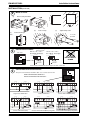
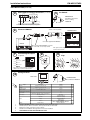
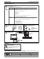
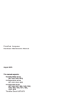
Installation Instructions
EM-MPO/STAR3
Electricity Meter
Important: Retain these instructions
UNPACKING
EM-MPO/STAR3
User Manual
TB200774
EM-MPO/STAR3
Installation Instructions
TG200771
STORING
+50 °C
-10 °C
20 %RH
H O
90 %RH
It is recommended that the installation should comply
with the HSE Memorandum of Guidance on Electricity
at Work Regulations 1989.
2
INSTALLATION
1
Choose the Location
14.5 mm
STAR3
STAR3
100.9 mm
Three phase energy analyzer
Three phase energy analyzer
PAG
STAR3
Three phase energy analyzer
PAG
SEL
SEL
SEL
SET
SET
96 mm
PAG
SET
96 mm
115.4 mm
STAR3
Three phase energy analyzer
PAG
-10 °C
+50 °C
Protection
H
2
20 %RH
O
SEL
SET
90 %RH
Instrument : IP20
Front panel : IP40
STAR3
STAR3
>3m
STAR3
Three phase energy analyzer
Three phase energy analyzer
PAG
SEL
SET
PAG
SEL
SET
Three phase energy analyzer
PAG
SEL
SET
EM-MPO/STAR3
ENC2/S
OK
TX
1
RX
2
1 2 3 4 5 6 7 8 9 10
EM-MPO/STAR3 Installation Instructions TG20771 Issue 1/B 07/04/05
1
EM-MPO/STAR3
Installation Instructions
INSTALLATION (continued)
2
(b)
Mount on Panel
Remove clamp from Meter
91 mm
(a)
Cut hole in Panel
91 mm
(d)
(c)
hole
(e)
Push on clamp
Tighten clamp screws
Push meter through
2 screws
provided
Two part screw terminal, maximum cable cross
section 2.5 mm2
Connect Power to Meter
3
230 Vac +15 % -20 %,
35 to 400 Hz, 4VA Supply
rear view
1
2
3
4
5
6
1
2
3
A
B
OUT
1A
4
5
OUT OUT
1B 2A
L
N
230 Vac
RS485
VL3
1
VL2
2
100 mA T
6
OUT
2B
115 Vac +15 % -20 %,
35 to 400 Hz, 4VA Supply
L
N
115 Vac
E
VL1
N
3
4
!
VOLTAGE INPUT
MAX 600V~
CAT 111
AL3 AL2 AL1 COM 0
0
I
200 mA T
E
DO NOT APPLY
POWER
115 230V~
5 6 7 8
9 10 11
!
!
9 10 11
0 115 230V~
CURRENT INPUT POWER SUPPLY
MAX 5A~
50/60Hz 6VA
9 10 11
0 115 230V~
4VA~ 50/60Hz
POWER SUPPLY
!
!
4VA~ 50/60Hz
POWER SUPPLY
Note that this instrument does not require an earth connection
1
2
3
4
5
6
Two part screw terminals, maximum cable cross section area 2.5 mm2
ABSOLUTE MAXIMUM CURRENT 5 A~
ABSOLUTE MAXIMUM VOLTAGE 600 V~
1
2
3
A
B
OUT
1A
4
5
OUT OUT
1B 2A
RS485
VL3
VL2
1
2
VL1
N
3
4
AL3 AL2 AL1 COM 0
9 10 11
!
!
2
3
N
4
AL3
5
AL2
6
VL3
COM
7
8
S1
S2
1
N
VL2
2
3
VOLTAGE
CURRENT
VL1
N
4
AL3
5
AL2
6
L1
LOAD
L
AL1
S1
L2
AL1
VL3
COM
7
8
S1
S2
S2
1
2
CURRENT
VL1
3
N
4
AL3
5
AL2
6
L1
S1
L2
L3
S1
AL1
VOLTAGE
COM
7
8
S1
S2
VL3
1
S2
VL2
2
3
N
4
AL3
5
AL2
6
S1
L2
L3
5
S1
S2
AL1
AL2
6
S1
AL1
COM
7
8
S1
S2
S2
S2
3 Phase without Neutral (Delta)
VOLTAGE
VL3
COM
7
8
S1
S2
1
VL2
2
CURRENT
VL1
3
N
4
AL3
5
AL2
6
L1
S2
S1
L2
N
L3
S1
AL1
COM
7
8
S1
S2
S2
S2
N
3 Phase with Neutral (Star)
2
4
AL3
S1
CURRENT
VL1
L1
S2
3
N
L3
LOAD
1
VL2
2
CURRENT
VL1
L2
2 Phase with Neutral
LOAD
VOLTAGE
VL3
VL2
L1
N
Single Phase with Neutral
CURRENT INPUT POWER SUPPLY
MAX 5A~
50/60Hz 6VA
LOAD
1
VOLTAGE
CURRENT
VL1
LOAD
VOLTAGE
VL2
115 230V~
5 6 7 8
!
VOLTAGE INPUT
MAX 600V~
CAT 111
VL3
6
OUT
2B
LOAD
Connect Measurement Connections
4
3 Phase without Neutral (Delta) using 2VTs
3 Phase with Neutral (Star) using 3CTs
EM-MPO/STAR3 Installation Instructions TG20771 Issue 1/B 07/04/05
Installation Instructions
EM-MPO/STAR3
INSTALLATION (continued)
Connect Measurement Connections (continued)
VOLTAGE
VL3
1
VL2
2
3
N
AL3
4
AL2
5
AL1
6
COM
7
8
S1
L1
S1
L2
Fix ENC2/S
5
CURRENT
VL1
NBOX/ENC2/S
Installation Instructions
Sheet 1, Fixing
TG200270
S2
LOAD
4
S2
L3
3 Phase without Neutral (Delta) using 2CTs
Connect to ENC2/S
red
blue
RS485 ← → RS232
A
RS485
ensure correct polarity
B A
6
1
2
B
EM-MPO/STAR3
1
2
3
4
5
6
1
2
3
A
B
OUT
1A
4
5
OUT OUT
1B 2A
6
OUT
2B
RS485
VL3
VL2
VL1
N
3
4
AL3 AL2 AL1 COM 0
115 230V~
3 m cable supplied with ENC2/S
ENC2/S
1
Note: ensure RS232/RS485 converter
is connected correct way round.
OK
RX
2
1 2 3 4 5 6 7 8 9 10
Connect Digital Outputs
7
1
2
3
4
5
6
3
4
1
2
3
A
B
OUT
1A
5
OUT OUT
1B 2A
On
!
VL3
VL2
1
2
VL1
N
3
4
!
VOLTAGE INPUT
MAX 600V~
CAT 111
Two part screw terminals, maximun cable cross
section area 2.5 mm2
9
Open
Flap
0
OUT
2B
RS485
5
OUT2A
9 10 11
!
CURRENT INPUT POWER SUPPLY
MAX 5A~
50/60Hz 6VA
6
OUT1
OUT1B
6
4
Switch
8
if required
OUT1A
5 6 7 8
!
TX
1
2
VOLTAGE INPUT
MAX 600V~
CAT 111
AL3 AL2 AL1 COM 0
I
115 230V~
5 6 7 8
9 10 11
!
!
CURRENT INPUT POWER SUPPLY
MAX 5A~
50/60Hz 6VA
OUT2
OUT2B
Two part screw terminals, maximum
cable cross section area 2.5 mm2
10
Configure Meter
STAR3
PAG + SEL
EM-MPO/STAR3
User Manual TB200774
Three phase energy analyzer
PAG
Pages
PAG
SEL
SET
Parameters
Default
VT Ratio
primary: secondary VT ratio
100:100
1
CT Ratio
primary: secondary CT ratio
5:5
2
Integration time for Average Power and Current
15 mins
Integration Period
Reset Counters
resets kWh, kVArh, kVAh
no
Reset Averages and Peaks
no
Cogeneration
to measure energy supplied back into mains yes/no
no
Connect type
3PH (Delta), 3PH And n (Star), 2PH (Diphase),
1PH (Single Phase)
3PH And n
Baud rate
default for ENC2/S
baud rate: 9.6 (9k6)
Parity
default for ENC2/S
parity:n (none)
Protocol
protocol:IEEE
MUST CHANGE PROTOCOL TO ASCI I
5
RS485 address
default for ENC2/S: 1
4
RS485
Address
1
2
3
4
5
Note
3
4
Default (100:100) for direct connect. Set up correct ratio if VT used.
Default (5:5) for direct connection. Set up correct ratio for CT used.
Change to match connection in step 4 above.
Default set for ENC2/S. Change back if it has been modified.
THE PROTOCOL MUST BE CHANGED TO ASCII
EM-MPO/STAR3 Installation Instructions TG20771 Issue 1/B 07/04/05
3
EM-MPO/STAR3
Installation Instructions
INSTALLATION (continued)
10
Configure Meter
(continued)
Pressing PAG again steps on to outputs below
OUTPUTS Page
PAG
Pulse Mode 100 mS
Pulse Mode 20 mA
Setting
101 SEC PLS
002 SEC PLS
Selects 100 mS or 20 mS pulse mode for both outputs
Then for each output Out1, Out2 select:
kWh total
kWh total COG
kVArh total
kVArh total COG
kVAh
Then for each output PLS1, PLS2 select units per pulse 1, 10, 100
(e.g. =for kWh,1 pulse = 1 kWh, 10 kWh, 100 kWh)
Relay Mode
Selects relay mode for both outputs
For Out1 only - Can set it to be remotely operated for RS485 (not used with ENC2/S)
Select parameter from which to generate alarms (see data sheet)
For each Output, Out1, Out2
Set high alarm level Out n H
Set low alarm level Out n L
Set hystersis (00 to 99 %) Hst n
Set delay (000 to 999s) dLy n
11
Close flap
Configure ENC2/S
12
NBOX/ENC2/S
Installation Instructions
Sheet 2, Configuration
TG200270
13
1
2
3
4
5
6
Check system
1
2
3
A
B
OUT
1A
4
5
6
OUT OUT
1B 2A
OUT
2B
RS485
VL3
VL2
VL1
N
1
2
3
4
AL3 AL2 AL1 COM 0
!
VOLTAGE INPUT
MAX 600V~
CAT 111
115 230V~
5 6 7 8
9 10 11
!
!
EM-MPO/STAR3
rear view
CURRENT INPUT POWER SUPPLY
MAX 5A~
50/60Hz 6VA
ENC2/S
LOAD
L1
L2
L3
OK
TX
1
N
RX
2
1 2 3 4 5 6 7 8 9 10
A
V
kW
Lan
DISPOSAL
WEEE Directive :
At the end of their useful life the packaging and
product should be disposed of via a suitable
recycling centre.
Do not dispose of with normal household waste.
Do not burn.
Trend Control Systems Ltd reserves the right to revise this publication from time to time and make changes to the content
hereof without obligation to notify any person of such revisions or changes.
P.O. Box 34, Horsham, West Sussex, RH12 2YF United Kingdom
Telephone +44 (0)1403 211888
Registered
4
office.
24
Queens
Road
Weybridge
Website www.trend-controls.com
Fax (International) +44 (0)1403 210982
Surrey
KT13
9UX
Registered
Fax (UK) +44 (0)1403 241608
in
England
No
1664519
EM-MPO/STAR3 Installation Instructions TG20771 Issue 1/B 07/04/05