1
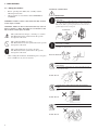
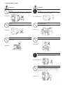
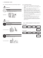
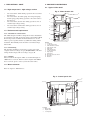
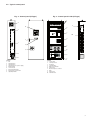
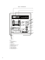
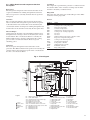
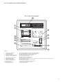
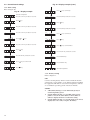
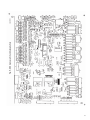
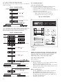
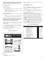
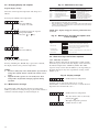
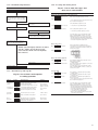
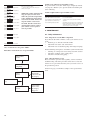
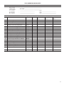
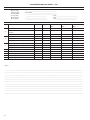
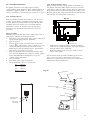
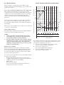
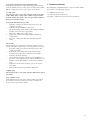
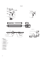
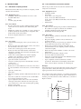
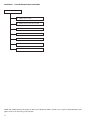
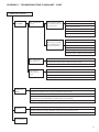
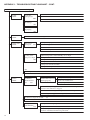
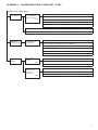
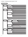
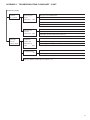
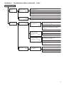
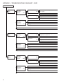
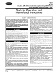
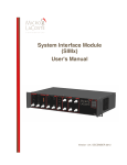
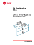
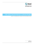
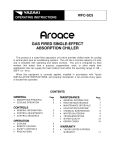
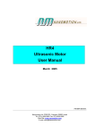
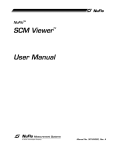
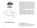
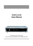
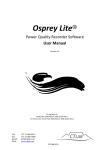
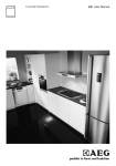
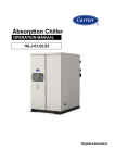
16TJ
Single-Effect Steam-Fired
Absorption Chillers
Nominal cooling capacity 352-2461 kW
50 Hz
Operation and maintenance instructions
GB/T-19001-2000 to ISO9001/2000
Notes to Users
Thank you for purchasing a Carrier/Sanyo absorption chiller.
Read this manual carefully before operating the unit. It contains instructions for the operation and maintenance of the chiller.
Please utilize the chiller to its optimum performance by carrying out the recommended daily maintenance and handling
instructions as well as the periodic service.
If you need any information about maintenance contracts or have any other enquiries, please contact your Carrier service agent.
Contents
1 - Precautions........................................................................................................................................................................... 4
1.1 - Safety precautions........................................................................................................................................................................ 4
1.2 - High-temperature - high-voltage caution.................................................................................................................................... 8
1.3 - Environmental requirements........................................................................................................................................................ 8
1.4 - Water treatment............................................................................................................................................................................ 8
2 - MACHINE IllustrationS................................................................................................................................................... 8
2.1 - Typical chiller detail.................................................................................................................................................................... 8
2.2 - Control panel............................................................................................................................................................................... 9
2.3 - Chiller flowchart and component function description............................................................................................................. 11
3 - Operating instructions............................................................................................................................................... 12
3.1 - Self-diagnostic function............................................................................................................................................................. 12
3.2 - Description of keys and their functions..................................................................................................................................... 13
3.3 - Control board settings................................................................................................................................................................ 14
3.4 - Operation................................................................................................................................................................................... 16
3.5 - Changing the information on the data display........................................................................................................................... 17
3.6 - Changing display and setpoint................................................................................................................................................... 18
3.7 - Maintenance message................................................................................................................................................................ 18
3.8 - Alarm messages and actions required........................................................................................................................................ 18
4 - Maintenance........................................................................................................................................................................ 20
4.1 - Daily maintenance..................................................................................................................................................................... 20
4.2 - Periodic maintenance................................................................................................................................................................. 23
4.3 - Recommended maintenance and main component replacement schedule................................................................................ 24
4.4 - Water treatment.......................................................................................................................................................................... 25
5 - Troubleshooting............................................................................................................................................................. 27
6 - Instructions........................................................................................................................................................................ 29
6.1 - Absorbent sampling method...................................................................................................................................................... 29
6.2 - Concentration measurement method......................................................................................................................................... 29
7 - Maintenance contract................................................................................................................................................ 31
7.1 - Annual maintenance contract..................................................................................................................................................... 31
7.2 - Inspection report........................................................................................................................................................................ 31
7.3 - Warranty..................................................................................................................................................................................... 31
Appendix 1 - Troubleshooting flowchart.....................................................................................................................................32-41
The cover photograph is for illustrative purposes only, and are not contractually binding.
1 - Precautions
1.1 - Safety precautions
•
•
Before operating this chiller, first carefully read the
following instructions.
All precautions are classified as either WARNING or
CAUTION.
WARNING: Failure to observe this instruction may result in
serious injury or death.
CAUTION : Failure to observe this instruction may cause an
injury or failure of chiller. Depending on circumstances, this
may result in serious injury or death.
1.1.1 Safety considerations
WARNINGS
TURN OFF THE BREAKER BEFORE CLEANING AND
CHECKING
Always turn off the circuit breaker before cleaning and checking
the cooling tower fan, chilled water pump, or other components
linked to the chiller, to provide protection from electric shock or
possible injury from the rotating fan.
INSPECTION
This symbol denotes danger, a warning or a caution.
The illustration in this symbol shows the specific
description of the item.
•
This symbol prohibits an action.
The illustration next to this symbol shows the specific
description of the item.
This symbol instructs an action to be done.
The illustration in this symbol shows the specific
description of the item.
After reading this manual, it should be kept in a safe place
to be available for any user at any time.
STOP OPERATION IN CASE OF FIRE, EARTHQUAKE OR
ELECTRICAL STORMS
Stop operation in case of fire, earthquake or an electrical storm, to
prevent fire or electric shock.
Must be observed
DO NOT TOUCH THE CONTROL PANEL SWITCH WITH
WET HANDS
Do not touch the switch inside the control panel with wet hands
to avoid electric shock.
SWITCH
Do not touch
DO NOT TOUCH THE WIRING INSIDE THE CONTROL
PANEL
Do not touch the wiring inside the control panel to avoid electric
shock.
Do not touch
DO NOT TOUCH HIGH-VOLTAGE CABLES
Do not touch high-voltage cables to avoid electric shock.
Do not touch
1 - Precautions - cont.
WARNINGS
CAUTIONS
KEEP FLAMMABLE substanceS AWAY FROM THE
chiller
SOLVE ALL PROBLEMS BEFORE RESTARTING THE
chiller
Do not place any flammable substances (e.g. gasoline, thinner)
close to chiller, flue, chimney and oil tank to prevent fire.
Solve all problems before restarting the chiller after a safety or
security device is activated, to prevent fire.
Prohibited
Must be observed
DO NOT OPERATE THE chiller IF THERE IS A SMELL
OF GAS
DO NOT PLACE HEAVY OBJECTS ON THE chiller
OR CONTROL PANEL
Do not operate the chiller if there is a smell of gas. Do not turn
on/off any switch, as this could cause a fire.
Do not place heavy objects on the chiller or control panel as
these may fall off and cause injuries.
Prohibited
Prohibited
DO NOT TOUCH ROTATING PARTS OF FANS
DO NOT CLIMB ON THE chiller
Keep away from rotating part of fans or pumps to avoid
possible injury.
Do not climb on the chiller as you may fall off.
Prohibited
Prohibited
CALL SPECIALISTS FOR SERVICE OR MAINTENANCE
Call specialists for service or maintenance. Incorrect service/
maintenance may cause electric shocks, fire or burns.
Must be observed
AUTHORIZED PERSONNEL ONLY
A notice, "For Authorized Personnel Only" must be affixed to
the chiller to stop unauthorized personnel from touching it. If
necessary surround the chiller by a protective fence. Misuse of
the chiller may cause injury.
Prohibited
1 - Precautions - cont.
CAUTIONS
DO NOT POUR WATER ON THE chiller OR CONTROL
PANEL
Do not pour water on the chiller or control panel to avoid electric
shock.
OBSERVE THE SPECIFIED WAter and steam PRESSURE
The specified chilled water, steam and cooling water pressure
must be strictly observed.
Incorrect pressure may cause the water to leak/spray which can
lead to short circuits or burns.
Prohibited
Must be observed
USE THE CORRECT POWER SUPPLY
This is indicated on the chiller name plate. Use of an incorrect
power supply may cause fire or electric shock.
Prohibited
DO NOT TOUCH HIGH-TEMPERATURE AREAS
Do not touch high-temperature areas, as they may cause burns.
These areas are indicated by caution label.
What
voltage?
Prohibited
NEVER CHANGE THE SET VALUES
Never change the set values of the safety and/or protective
devices. Wrong settings may damage the chiller or cause fire.
STOP THE PURGE PUMP TO REPLACE OIL
Stop the purge pump when replacing oil to avoid possible injury
by fuel spillage.
Prohibited
STOP
Must be observed
STOP THE OPERATION WHEN COmbustion smoke is
BLACK
Stop the operation when combustion smoke is black and call a
service engineer..
Must be observed
DO NOT TOUCH THE ABSORBENT
Do not touch the spare or leaked absorbent, as this can cause
metal corrosion or skin disease.
Prohibited
1 - Precautions - cont.
1.1.2 - Safety precautions for repair, moving or disposal
WARNINGS
ONLY AUTHORIZED PERSONNEL SHOULD service
THE chiller
Only authorized personnel should service the chiller. Incorrect
service could result in electric shock or fire.
Prohibited
1.1.3 - Operating precautions
1. Keep the purge valve tightly shut to prevent air from
leaking into the chiller, which may cause the failure of the
chiller.
2. Keep the power supply to the control panel turned on,
unless carrying out maintenance or service.
3. During the chiller dilution cycle the chilled-water pump
(both the primary side and the secondary side) and air
handling unit must be operated for the required time. The
chiller has some cooling capacity, even in the dilution
cycle. Do not stop the air handling unit before the required
time to prevent possible subcooling.
4. Do not perform an insulation test on the control circuits of
the electric controller.
5 . Use a Carrier recommended interlock system to stop/
start the auxiliary equipment. The interlock system
automatically stops/starts the chilled-water pump and
cooling water pump. Please follow the start procedure in
Figure 1 below.
CAUTION
ONLY AUTHORIZED PERSONNEL SHOULD REMOVE OR
REPAIR THE chiller
Any relocation or moving of the chiller should only be done by
authorized personnel. Incorrect work could result in water leaks,
electric shock or fire.
Fig. 1 - Auxiliary equipment start/stop sequence
Start sequence
1: Chilled
water pump
2: Cooling
water pump
3: Cooling
tower
4: Absorption
chiller
5: Air
handling
unit
Must be observed
Stop sequence
1 Absorption
chiller
ONLY AUTHORIZED PERSONNEL SHOULD DISPOSE OF
THE chiller
To dispose of the chiller, contact local specialists. Incorrect
disposal may result in absorbent leaks and cause metal corrosion
or skin disease, electric shock or fire.
2: Cooling
water pump
3: Cooling
tower
4: Chilled
water pump
5: Air handling
unit
Must be observed
1 - Precautions - cont.
2 - MACHINE IllustrationS
2.1 - Typical chiller detail
1.2 - High-temperature - high-voltage caution
•
•
•
•
Fig. 2 - Water header side
Do not touch the chiller during operation since its surface
becomes hot.
Do not touch the absorbent pump, the refrigerant pump,
and the purge pump during operation, since their surface
becomes hot.
Do not touch the junction box during operation, since it
contains high-voltage wiring.
Do not touch the terminal box during operation, since it
contains high-voltage wiring.
1
10
2
3
6
1.3.1 - Installation considerations
The 16TJ absorption chiller is designed for indoor installation
in a machine room. The protection rating of the chiller is IP40.
Room temperature should be maintained between 5°C and
40°C to protect against solution crystallization during chiller
shutdown. The humidity in the machine room must be kept
below 90%.
7
1.3.3 - Altitude
Please install the absorption chiller at a maximum height of
1000 m above sea level. If the location is higher than 1000 m
above sea level, please contact your local Carrier office.
11
4
5
1.3 - Environmental requirements
1.3.2 - Field wiring
The machines should be connected to a power source that
complies with overvoltage category III (IEC 60664). All other
wiring should comply with overvoltage category II.
9
12
8
Legend
1 Condenser
2 Cooling water outlet
3 Chilled water flow switch
4 Chilled water outlet
5 Evaporator
6 Chilled water inlet
7 Cooling water inlet
8 Purge pump
9 Steam inlet
10 Generator pressure switch
11 Generator
12 Absorber
1.4 - Water treatment
Refer to chapter 4 "Maintenance”.
Fig. 3 - Control panel side
2
3
1
Legend
1 Drain outlet
2 Rupture disk
3 Control panel
2.2 - Typical control panel
Fig. 4 - Control panel (CE type)
Fig. 5 - Control panel inside (CE type)
1
1
2
6
9
2
3
7
3
8
9
10
4
5
6
4
7
5
8
Legend
1 Fan
2 Terminal block
3 Terminal block
4 Terminal block for power supply
5 Earth terminal
6 Control board
7 Purge indication light
8 Purge pump on/off switch
9 Operating handle
Legend
1 Control relay
2 Circuit protector
3 I/O board
4 Circuit breaker
5 Main circuit breaker
6 Transformer
7 Electromagnetic contactor
8 Filter
9 Transformer
10 Terminal block
Fig. 6 - Control board
1
2
3
4
STOP
RUN
5
CHILLER
6
ABS PUMP
REF PUMP
SET
BACK
PURGE PUMP
7
REMOTE
8
STAND BY
DILUTION
SAFETY CIRCUIT
CHILLER ALARM
BUZZER STOP
LOCAL
9
OPERATION
STOP
RUN
POWER
10
11
12
13
14
Legend
1 Stop indication light
2 Operation indication light
3 Data display
4 Select key
5 Function set key
6 Back select key
7 Remote/local select key with LED
8 Alarm buzzer stop key
9 Operation select key with LED
10 Alarm indication light
11 Stand-by indication light
12 Dilution indication light
13 Safety circuit indication light
14 Power indication light
10
2.3 - Chiller flowchart and component function
description
Condenser
The refrigerant vapour from the generator is condensed on the
heat transfer tubes of the condenser. Cooling water from the
absorber is heated by condensation heat.
Evaporator
The refrigerant is dispersed on the heat transfer tubes of the
evaporator. Chilled water running through the heat transfer
tubes of evaporator is cooled by the latent heat of vaporized
refrigerant.
Purge unit
The purge unit collects the non-condensable gas in the chiller
and stores it in the purge tank.
Sensors
Absorber
The concentrated solution is dispersed on the heat transfer
tubes of absorber. The refrigerant vapour from the evaporator
is absorbed on the heat transfer tubes of the absorber by the
concentrated solution. Cooling water running through the heat
transfer tubes of the absorber is heated by the absorption heat.
SymbolName
DT1
Chilled-water leaving temperature
DT2
Cooling water leaving temperature
DT3
Generator temperature
DT5
Condenser temperature
DT6
Chilled-water entering temperature
DT7
Cooling water entering temperature
DT8
Not used
DT9
Not used
DT10
Diluted solution temperature at absorber outlet
DT11
Evaporator refrigerant temperature
DT12
Cooling water mid-temperature
DT13
Steam drain temperature
23CH
Temperature controller
69CH
Chilled water flow switch
PCH
Palladium cell heater
69PR
Purge tank pressure
Heat exchanger
After leaving the absorber section the diluted solution passes
through the heat exchanger, where it is heated by the concentrated solution. The concentrated solution is cooled by the
diluted solution. Due to the lower temperature this cooling
process of the concentrated solution allows for greater
absorbing power.
Generator
The steam passes through the heat transfer tubes of the
generator. The diluted solution in the generator is heated by the
steam. It releases the refrigerant vapour and is concentrated to
become a concentrated solution.
Fig. 7 - Flow diagram
18
19
11
DT2
12
6
69PR
V2
PCH
DT5
63GH
SV7
13
20
D7
7
DT12
21
DT3
V3
DT13
2
DT1
69CH
3
SV2
DT6
SV1
4
V1
15
14
DT11
1
SV3
5
DT10
SV6
D1
8
DT7
SV4
9
10
Legend
Sensor
Service valve
Damper
Check valve
Valve
17
16
23CH
D1: Diluted solution main damper
1: Purge pump
D7: Steam drain damper
2: B-valve (manual purge valve)
SV1:Charge/removal service valve N2 gas
3: Chilled-water outlet
SV2:Purge unit service valve
4: Chilled-water inlet
SV3:Refrigerant service valve
5: Purge unit
SV4:Diluted solution service valve
6: Cooling water outlet
SV6:Concentrated solution service valve
7: Purge tank
SV7:Generator pressure gauge service valve
8: Refrigerant pump
V1: Manual purge valve
9: Refrigerant blow-down valve
V2: Manual purge valve
10: Absorption pump
V3: Manual purge valve
11: Rupture disk
12: Condenser
13: Generator
14: Evaporator
15: Absorber
16: Cooling water inlet
17: Heat exchanger
18: Steam control valve
19: Steam inlet
20: Steam drain reclaimer
21: Steam drain outlet
11
3 - Operating instructions
3.1 - Self-diagnostic function
The self-diagnostic function starts when the breaker inside the
control panel of the chiller is turned on. After self-diagnosis
is completed, the data display on the control board shows the
following information.
•
•
Data display (7-segment LED) and all LEDs light up.
If there is no abnormality the data display shows the
version number. If there is a power failure, H-10 is
displayed after the power is restored.
Fig. 8 - Control panel
Note: The version number differs with each chiller type.
•
The data display shows the generator temperature.
(120.4)
If the self-diagnosis function detects an error, this will be
shown on the data display. For the alarm indication, please
refer to chapter 3.8.
12
3.2 - Description of keys and their functions
Fig. 9 - Typical control board
6
1
2
STOP
11
RUN
CHILLER
ABS PUMP
REF PUMP
7
SET
8
9
12
REMOTE
4
STAND BY
DILUTION
SAFETY CIRCUIT
10
BACK
PURGE PUMP
CHILLER ALARM
POWER
BUZZER STOP
LOCAL
OPERATION
STOP
RUN
5
3
Legend
1 Operation indication light:
2 Stop indication light:
3 Alarm indication light:
4 Remote/local select key with LED:
5 Operation select key with LED:
6 Data display (7-segment LED):
7 Standby indication light:
8 Dilution indication light:
9 Safety circuit indication light:
10 Power indication light:
11 Data select key:
12 Alarm buzzer stop key:
The operation indication light is on when the chiller is running.
The stop indication light is on when the chiller is shut down.
The alarm indication light is on when an alarm occurs.
To select remote operation or local operation.
Key used to run/stop the chiller.
The stop key is also used for alarm reset.
Shows the temperature, setpoint, etc.
On when the chiller is waiting for the interlock signals form the chilled water and the cooling water pump.
On during the dilution cycle.
On when power is supplied to the control circuit.
On when power is supplied to the control circuit.
To change the menu and set a new value.
To stop the alarm buzzer.
13
3.3 - Control board settings
Fig. 10 - Display example (cont.)
3.3.1 -Time setting
Refer to Figure 10.
!!!!
Fig. 10 - Display example
Generator temperature
Press the " SET " key for about 2 seconds.
Press
Press
key to set the day.
!!!!
Press the SET key for about 2 seconds.
key.
Press
key.
Press the " SET " key for about 2 seconds.
Press the SET key for about 2 seconds.
Press the " SET " key for about 2 seconds.
!!!!
Press
!!!!
Press
key to set the hour.
Press
key.
Press
key to set the minutes.
!!!!
or
key.
!!!!
Press the " SET " key for about 2 seconds.
!!!!
Press
!!!!
key.
Press the SET key for about 2 seconds.
Press the SET key for about 2 seconds.
Press the BACK key.
!!!!
Press
key to set the month.
Press the BACK key.
!!!!
Press
key.
Generator temperature
3.3.2 - Battery backup
Refer to Figure 11.
SW3
Connect a backup battery which is used to maintain the time
setting when a power failure occurs. Turn it ON after installing
the equipment. CR-2025 is used as the backup battery and has
an accumulative operating period of about six months.
NoteS:
1. SW3 (battery backup) is set to OFF at the factory to
avoid using battery power.
2. If SW3 (battery backup) is set to OFF when a power
failure occurs, F-21 (CPU alarm) or F-23 (Time set
alarm) is displayed. Please reset the time setting.
3. If SW3 (battery backup) is set to ON and F-21 or F-23 is
displayed, it is necessary to replace the battery.
14
15
LABEL
SW3: Backup switch
UP:
ON
DOWN: OFF
Backup battery
Fig. 11- SW3 backup switch and backup battery
3.3.3 - How to change the temperature unit
The temperature unit can be changed as follows, even while the
chiller is operating.
Fig. 12 - Display example
Press the " SET " key
for about 2 seconds.
Generator
temperature
Press
or
key.
3.4 - Cooling operation
3.4.1 - Pre-operation checks
Please check the following items before starting operation:
• Check the setpoint of the chilled-water leaving
temperature. Make sure that the chilled-water leaving
temperature is set as specified. For the indication of the set
value, please refer to chapter 3.8.
• Check the steam and steam drain equipment
- Make a daily inspection (refer to chapter 4).
- Check that the steam valve(s) is (are) open.
Fig. 14 - Control board
Press the SET key
for about 2 seconds.
Press
or
key if you need.
Press the SET key
for about 2 seconds.
And push
or
key.
To select °C
To select °F
Press the "SET" key to select °C mode and again to select the °F mode
3.3.4 - Changing remote signal setting (continuous, pulse etc.)
After wiring of the remote signal, the control board shown
below should be set. Refer to field wiring diagram.
STOP
RUN
CHILLER
ABS PUMP
Fig. 13 - Display example
REF PUMP
SET
BACK
PURGE PUMP
Control board setting
1
Remote
signal type
REMOTE
(1)
(2)
DILUTION
(3)
SAFETY CIRCUIT
(4)
(5)
free
or
Press the
or
key.
Press the
or
key.
Press the SET key for about 2 seconds.
Then press the
or
key.
To select the static mode
By pressing the SET key, the
static mode is selected.
To select the pulse mode
By pressing the SET key, the pulse
mode is selected.
Press the SET key for about 2 seconds.
Then press the
or
key.
16
POWER
STOP
3
RUN
4
Legend
1 Remote key
2 Local key
3 Stop key
4 Run key
key.
Press the SET key for about 2 seconds.
To select the negative mode
To select the positive mode
Press SET key to select positive mode.
LOCAL
OPERATION
CHILLER ALARM
Press the
BUZZER STOP
free
Generator temperature Press the SET key
for about 2 seconds.
2
STAND BY
Press SET" key to select negative mode.
NOTE: If the chilled-water pump, cooling water pump, and
chiller are interlocked, each pump runs automatically when
starting the chiller. If not, the start sequence must be:
Chilled-water pump, cooling water pump, chiller.
3.4.2 - Start cooling operation
Refer to Figure 14.
Local operation mode
• Press the "LOCAL" key on the chiller control board. The
"LOCAL" indication light of the key is on.
• Keep pressing the "RUN" key for more than a second and
make sure that the "RUN" indicator lightp of the key is on.
• Automatic operation starts.
Remote operation mode
• Press the "REMOTE" key on the chiller control board.
The "REMOTE" indicaton light of the key is on.
• Turn on the start switch on the remote control panel for
the field supply. The indicator light of the "RUN" key on
the chiller control board is on.
• Automatic operation starts.
NOTE: In local operation mode the signal from the remote
control panel does not work. In remote operation mode the
"RUN" key of the chiller control board does not work.
It returns to the generator temperature display when no key is
pressed for 1 minute.
3.5.2 - Changing the display
Refer to Figure 15.
3.4.3 - Stop operation
Refer to Figure 14.
Local operation mode
• Keep pressing the "STOP" key on the chiller control board
for more than a second.
• Make sure that the "RUN" indication light goes off and the
"STOP" indication light comes on.
Remote operation mode
• Turn on the stop switch on the field supply remote control
panel.
• Another way to stop the chiller is to press the "STOP" key
on the chiller control board during remote operation.
NOTE: If the chilled-water pump, cooling water pump, and
chiller are interlocked, each pump stops automatically when
the chiller stops. If not, the stop sequence must be:
Chiller, cooling water pump, chilled-water pump
The air handling unit must be stopped after the chilled-water
pump is stopped
If you press the key, the information on data display changes
in the correct order, and pressing the key, it changes in
reverse order.
If you press the key again when the last information is
shown, the display returns to the normal display information.
3.5.3 - Typical display order
Real-time data is shown in the data display (7-segment
LED and 6 figures). The display shows a data code (content
distinction by code number) and various operating times, on/off
time, component temperatures, chilled-water temperature
setpoints and alarm codes. A data code is sent in turn from
the
keys and displayed. An alarm code is only shown
when one or several abnormalities occur. The alarm code is
shown in order of importance, and a dotted "." is shown under
the number to the right of the alarm code. When several faults
occur, use the
keys to display the additional alarm codes.
If no key including the "BACK" key is pressed for 1 minute,
the display returns to the generator temperature display.
Fig. 16 - Typical display order
3.5 - Changing the information on the data display
Data code
-
1.
2.
3.
4.
5.
6.
7.
8.
9.
A.
B.
C.
10.
11.
12.
13.
14.
15.
16.
17.
-
3.5.1 - Normal display information
The data display on the control board usually shows the
generator temperature as follows.
Fig. 15 - Control board
1
Data name
Display
Generator temperature
Chiller operating hours
Absorbent pump operating hours
#2 absorbent pump operating hours
Combustion hours
Refrigerant pump operating hours
Purge pump operating hours
Chiller on/off times
Absorbent pump on/off times
#2 absorbent pump on/off times
Combustion on/off times
Refrigerant pump on/off times
Purge pump on/off times
Chilled-water temperature setpoint
Hot-water temperature setpoint*
Chilled-water entering temperature
Chilled-water leaving temperature
Cooling water entering temperature
Condenser temperature
Steam drain/exhaust gas temperature
Purge tank pressure
Generator temperature
Means
135.0°C
1234 hours
1111 hours
Not used
Not used
1201 hours
107 hours
123 times
169 times
Not used
Not used
138 times
51 times
7.0°C
Not used
11.9°C
6.8°C
31.8°C
34.7°C
211.7°C
8.5 kPa
135.0°C
* Hot-water reference is not applicable to 16TJ units
2
STOP
RUN
CHILLER
ABS PUMP
REF PUMP
SET
BACK
3
PURGE PUMP
REMOTE
STAND BY
DILUTION
SAFETY CIRCUIT
CHILLER ALARM
BUZZER STOP
LOCAL
OPERATION
STOP
RUN
POWER
Legend
1 Data display
2 Select key: changes the data display information
3 Back select key
17
3.6 - Changing display and setpoint
Setpoint display change
Select the current setpoint temperature and change it as
follows.
To change the chilled-water temperature:
7.0°C
Press the SET key
for about 2 seconds.
A number showing the setpoint
temperature blinks.
Press the
or
key.
Fig. 17 - Maintenance message
Data code Data name
Display
H-01*
Operate purge pump
H-03*
Clean cooling water tubes
H-04*
Check cooling water system
H-06**
Purge tank high pressure
H-07**
Cooling water tubes foul
H-08**
Cooling water high temperature
H-10
Power failure
Legend
* When this appears, immediate action is required.
** When this appears, no immediate action is required, but as this might lead to
a higher code, attention should be paid. Consult Carrier service personnel at
the next periodic maintenance.
Note: These displays disappear when the problem has been
corrected.
Fig. 18 - Maintenance message descriptions and
actions required
Maintenance
message
Display
Maintenance
Message DisplayAction
1 Fouling
cooling
water of
tubes
1 Cooling
water tubes
foul
7.5°C
Press the SET key
Means
Operate purge pump.
Fouling of cooling water tubes.
Check cooling water pump,
cooling tower, etc.
Purge tank pressure is high.
Fouling of cooling water tubes.
Cooling water temperature is high.
There was a power failure while
the chiller was operating
2 Vacuum
rate
2 Vacuum
rate
3 Cooling water
3 High temperature
high temperature
of cooling water
Action
Cooling water tubes must be cleaned.
Cooling
water
tubes must
be cleaned.
Contact
Carrier
service
agent to do the job
Contact Carrier/SANYO service agent to do the job.
The purge tank must be purged immediately.
contact
The
purge
tank must is
beshown
purged immediately.
If this
message
frequently,
Inyour
case Carrier
this indication
is shown
frequently,
service
agent.
contact Carrier/SANYO service agent.
Check the cooling water pump, cooling tower, etc.
Check the cooling water pump, cooling tower, etc.
4 Power4 failure
Power failure
See
section
3.8.5.
See
section
3-8-5.
3.8 - Alarm messages and actions required
The setpoint change has been made.
If no key including the "BACK" key is pressed for 1 minute,
the display returns to the generator temperature.
NOTES:
1. Incorrect setting may cause chiller failure. If you need to
change the setpoint, always consult your Carrier service
agent.
2. Setpoints become effective as soon as they have been
changed. Be careful when changing setpoints during
operation.
3.7 - Maintenance message
If a problem that could affect the efficient operation of the
chiller is predicted, a warning message is given. This includes a
comment on the data display as shown in Figure 17.
18
3.8.1 - How they are shown
When an alarm is detected, the alarm buzzer sounds, and the
alarm message is shown on the data display. At the same time,
the indication light of the "STOP" key blinks. The chiller
stops for safety reasons after the dilution cycle. Depending on
the alarm message it may also stop without carrying out the
dilution cycle.
Fig. 19 - Display example
Chilled-water low temperature
An alarm code is only shown when one or several
abnormalities occur. If several errors have occurred, the most
important one is shown with a dot ".".
Chilled-water low temperature
The other alarm codes are shown by
pressing the key.
The high-temperature generator
solution level is too low.
3.8.2 - Troubleshooting flowchart
3.8.4 - Locating and clearing alarm
Fig. 21 - List of alarm messages and
their causes and remedies
SymptomsAction
An alarm occurs.
Display and content of alarm
Alarm of the chilled water and/or cooling water system
Check that the discharge pressure of both chillledChilled water temperature is too low.
water and cooling water pumps is normal.
Alarm buzzer sounds, and the
indication light of the "STOP" key blinks.
The alarm message is shown in the data
display.
Press the "BUZZER STOP" key on the
control board.
The alarm buzzer stops.
Check alarm message and solve the problem.
Press the "STOP" key on the control board
after the troubleshooting is completed.
The indication light of the "STOP" key
stops blinking and remains lit. The alarm
code on the data display disappears.
Note: If the data display still shows an alarm,
after the "STOP" key has been pressed,
ensure that the alarm cause has definitely
been removed.
Start operation
Operation restarts.
3.8.3 - Alarm message and setpoint
Fig. 20 - List of alarms and setpoints
in cooling operation
DisplayAlarm messageSetpoint
Protection of
Chilled water temperature is too low.
chilled water
Chilled water pump interlock alarm.
system
Chilled water flow alarm
Cooling water temperature is too low.
Prevention of
Cooling water pump interlock alarm.
Crystallisation
Cooling water flow alarm (option)
Generator temperature is too high.
2.5°C or below
50% or below
Below monitoring
temp. for 30 mins.
50% or below
105°C
Generator Generator pressure is too high.
protection
High concentration of absorbent
0 MPa or above
Motor
protection
Rated current
value or above
"
Absorbent pump overload alarm.
Refrigerant pump overload alarm.
Purge pump overload alarm.
Alarm of the motor(s)
Absorbent pump overload alarm.
Refrigerant pump overload alarm
→ If not, the strainer may be clogged, or there may
be an air leak in the piping, etc.
Is the chilled-water setpoint too low?
→ Correct it to the specified setpoint.
Is the cooling water setpoint too low?
→ Correct it to specified setpoint (e.g. 28°C).
Correct the above causes and restart the chiller.
If the "CHILLER ALARM" continues, check the
following and contact your Carrier service agent:
• Entering and leaving chilled-water temperature
• Entering and leaving cooling water temperature
• Generator temperature and pressure
First check that the reset button(s) of the
overload relay connected to the electromagnetic
contactor is not pushed in, and then contact your
Carrier service agent.
Reset buttons
Alarm
of the auxiliary equipment
Chilled water pump interlock alarm.
Check that the chilled-water pump and cooling
water pump are rotating.
→ Start the pumps
Cooling water pump interlock alarm.
Check the fan and/or other equipment connected
to the system interlock.
Correct the above causes and restart the chiller.
If the "CHILLER ALARM" continues, contact your
Carrier service agent.
Purpose
Chilled water flow alarm
Cooling water temperature is too low
Cooling water flow alarm (option)
Generator alarm
Generator temperature is too high.
Generator pressure is too high.
Check that the cooling water pump is rotating.
→ Start the pump.
Check that the cooling water line valve is open.
→ Open the valve.
Check that the cooling water pump discharge
pressure is normal.
→ If not, the strainer may be clogged, or there may
be an air leak in the piping, etc.
High concentration of absorbent
Correct the above causes and restart the chiller
If the "CHILLER ALARM" continues, check the
following and contact your Carrier service agent:
• Entering and leaving chilled-water temperature
• Entering and leaving cooling water temperature
• Generator temperature and pressure.
• Is the chilled water setpoint too low?
→ Correct it to the specified setpoint.
• Water in the heat transfer tubes may be fouled
(especially cooling water).
65% or above
19
Sensor alarm
Entering chilled-water temperature
sensor alarm.
Entering cooling water temperature
sensor alarm.
Leaving cooling water temperature
sensor alarm.
Cooling water intermediate
temperature sensor alarm.
Condenser temperature sensor alarm.
Steam drain temerature sensor alarm
Refrigerant temperature sensor alarm
(evaporator).
Diluted solution temperature sensor
alarm (absorber outlet).
Leaving chilled-water temperature
sensor alarm.
Generator temperature sensor alarm.
Purge tank pressure sensor alarm.
Is the sensor short-circuited?
→ Check all chiller sensors and contact your
Carrier service agent.
NOTE: The chiller automatically
stops for safety reasons when
either the generator temperature
or the chilled-water temperature
sensor has an alarm. It does not
stop when other sensors have
an alarm, but this could cause
control failure. Please contact
your Carrier service agent as
soon as possible.
The chiller stops
completely.
Power
returns.
20
Occurred during cooling operation, and
power did not return for over an hour
Immediately contact your Carrier service agent.
Do not restart operation.
Occurred during cooling operation, and
power returned in less than an hour
Contact Carrier service agent after restarting
operation.
Occurred during purging operation
Immediately close the purge valve completely and
turn the purge pump switch on the control panel
off. After the power is restored, restart purging,
and consult your Carrier service agent.
4.1.1 - Inspection of each chiller component
If you find an abnormal condition, contact your Carrier service
agent:
• Smell of gas or oil leak around the chiller
• Abnormal noise at the start of the burner
• Abnormal noise of absorbent pump and refrigerant pump
For the following items please consult the system manufacturer:
• Cleaning of cooling tower and cooling water line strainer
• Check the condition of the cooling tower
• Check for air leaks in the piping
4.1.2 - Operation data record
Please record the operation data regularly, as this is useful for
troubleshooting and alarm prevention. Show the record to the
Carrier service personnel when they visit you for the service or
the periodic inspection.
Power failure
alarm H-10
is shown on the
data display.
Press the "RUN"
key.
Operation
restarts.
Operation condition at power failureAction
4.1 - Daily maintenance
Flowchart of actions in case of a power failure
Power failure
occurs.
Actions required when a power failure occurs
4 - Maintenance
3.8.5 - Action in case of a power failure
Actions to be taken if a power failure occurs
If a power failure occurs, the chiller stops completely without
carrying out a dilution cycle. Special attention should be paid
to the following.
Power failure
alarm on the
data display
disappears.
On the next page you will find a sample of the operation data
sheet.
TEST OPERATION DATA SHEET
Trial run data sheet
Project name
chiller model
Serial number
Accepted by
Reviewed by
Recorded by
1/2
: _ ________________________________________
: TSA-16TJ-________________________________
: _ ________________________________________
: _ ___________________________ Date_ __________________________
: _ ___________________________ Date_ __________________________
: _ ___________________________ Date_ __________________________
Unit model/serial No.
No. Data items
Operator:
Unit
1
2
3
4
5
6
7
8
9
10
11
12
13
14
15
16
17
18
19
Ambient temperature
Room temperature
Chilled water entering temperature
Chilled water leaving temperature
Chilled water entering pressure
Chilled water leaving pressure
Evaporator pressure drop
Chilled-water flow rate
Cooling water entering temperature
Cooling water leaving temperature
Cooling water entering pressure
Cooling water leaving pressure
Pressure drop in absorber & condenser
Cooling water flow rate
Steam consumption
Supply steam pressure
Supply steam temperature
Generator temperature
Evaporator solution level
20
Purge tank pressure
°C/°F
°C/°F
°C/°F
°C/°F
kPa/psi
kPa/psi
kPa/psi
l/s/gpm
°C/°F
°C/°F
kPa/psi
kPa/psi
kPa/psi
l/s/gpm
kg/h/lb/h
kPa/psi
°C/°F
°C/°F
n/60 mm
n/2-3/8"
kPa
Spec.
DATA-1
Time:
Date:
DATA-2
Time:
/
/
DATA-3
Time:
21
TEST OPERATION DATA SHEET - cont.
Trial run data sheet
Project name
chiller model
Serial number
Accepted by
Reviewed by
Recorded by
Unit model/serial No.
No. Data items
2/2
: _ ________________________________________
: TSA-16TJ-________________________________
: _ ________________________________________
: _ ___________________________ Date_ __________________________
: _ ___________________________ Date_ __________________________
: _ ___________________________ Date_ __________________________
Operator:
Unit
Spec.
DATA-1
Time:
Date:
DATA-2
Time:
/
/
DATA-3
Time:
Concentration of concentrated solution %
Relative density of concentrated
21
solution
Temperature of concentrated solution
°C/°F
Concentration of diluted solution
%
22 Relative density of diluted solution
Temperature of diluted solution
°C/°F
Concentration of refrigerant
%
23 Relative density of refrigerant
Temperature of refrigerant
°C/°F
24 Condensed refrigerant temperature
°C/°F
25 *LTD (See below)
°C/°F
26 Absorbent pump current
A
27 Refrigerant pump current
A
28 Purge pump current
A
* LTD = Condensed refrigerant temperature minus cooling water leaving temperature
Notes:
_______________________________________________________________________________________________________
_______________________________________________________________________________________________________
_______________________________________________________________________________________________________
_______________________________________________________________________________________________________
_______________________________________________________________________________________________________
_______________________________________________________________________________________________________
_______________________________________________________________________________________________________
_______________________________________________________________________________________________________
_______________________________________________________________________________________________________
_______________________________________________________________________________________________________
_______________________________________________________________________________________________________
22
4.2 - Periodic maintenance
To optimize performance, the chiller requires purging,
refrigerant blow down, absorbent control, and management of
combustion equipment (16DJ), etc. We recommend that you
arrange a maintenance contract with your Carrier service agent.
4.2.2 - Refrigerant blow down
During cooling operation a small quantity of absorbent can
mix with the refrigerant. This amount can increase over time
and result in a reduced cooling capacity. Therefore refrigerant
blow-down must be performed once during the cooling season.
By doing this the dirty refrigerant is transferred to the absorber
side and new, clean refrigerant is regenerated.
4.2.1 - Purging (Fig. 23)
Fig. 22
Non-condensable gas inside the machine not only decreases
cooling capacity, but also potentially shortens the life of the
machine. Therefore purging must be done periodically. This
should be done by the Carrier service personnel under the
maintenance contract. If customers carry out the purging
themselves, they should take instruction from our service
personnel.
Purge procedure
When the purge indication light on the control panel comes on,
start purging, following the instructions below.
1. Turn on the purge pump on/off switch on the control panel
and operate the purge pump for 10 minutes.
2. Open V1 and V2.
3. Press the key on the control board once to show data
code 17 "Purge tank pressure" (refer to chapter 3.5.3) and
check if the indicated value drops. If it does not drop,
follow the procedure described in steps 5, 6 and 7 below,
and contact your Carrier service agent.
4. Purge for 10 minutes. Even if the purge indication light
goes off before 10 minutes have elapsed, continue purging
for the full 10 minutes. If the light does not go off,
continue purging until it does.
5. Close V1 and V2.
6. Turn off the purge pump on/off switch.
7. Check whether the valves are open/closed.
V1
Closed
V2
Closed
V3
Closed
B-valve Open
Refrigerant
blow-down valve
•
Make sure the refrigerant pump is rotating and that the
solution level is visible through the evaporator sight glass.
Open the transfer valve completely.
When the solution level is no longer visible, close the
transfer valve tightly.
•
•
The above blow-down procedure should be repeated a few
times, as necessary. We recommend that you arrange a
maintenance contract with your Carrier service agent which
will include refrigerant blow-down.
Fig. 23
Purge tank
B-valve
V2
V3
Maintenance pressure
gauge
SV2
SV1
V1
Liquid trap
Purge indication
light (green)
Purge pump
on/off switch
Purge pump
23
24
X
Heat exchanger tube
Water-line packing
Palladium cell
Other packing
X
X
X
X
X
Inverter
Diaphragm valve packing
X
Relay
X
X
Electro-magnetic contactor
Sight glass
X
Temperature sensor
Others
X
Flow switch
Control device
Purge pump
(X)
(X)
Refrigerant pump
Pressure switch
X
Absorbent pump
Pump
X
X
X
Safety device
X
Absorbent
Solution
(X)
X
Cooling water line pipes
Generator
X
Chilled-water line pipes
Main shell
Periodic replacement
V-belt
Periodic inspection with a maintenance contract.
Periodic replacement ((in order to avoid leakage)
Idem above
Periodic inspection with a maintence contract
Periodic inspection with a maintenance contract
Periodic replacement (because of safety device)
Overhaul
Overhaul
Overhaul
Solution random inspection
Visual inspection etc.
Overhaul
Eddy-current test/endoscope/visual
inspection
Visual inspection
Eddy-current test/endoscope/visual
inspection
Visual inspection
Method
Pump body
Pump body, impeller, bearing, motor
Pump body, impeller, bearing, motor
Alkalinity
Inhibitor ratio
Copper dissolution ratio
Iron dissolution ratio
Solution analysis
Concentration
Check the inside fouling
Corrosion of the heat transfer tube
surface. Reduced metal by abrasion
scale and/or slime adhesion
Corrosion of the heat transfer tube
surface. Scale and/or slime adhesion
Corrosion of the heat transfer tube
surface
Corrosion of the internal surface of the
heat transfer tube scale and/or slime
adhesion
Corrosion of the heat transfer tube
surface
Item
Vacuum
area
Nonvacuum
area
Inspection
Area inspection
Type
Component
Every 3 years
Every 3 years
Every 3 years
Every 3 years
Every 3 years
Once a year
As necessary
As necessary
Every 3 years
As necessary
As necessary
As necessary
As necessary
Two to four times
per year
Once a year
As necessary
Once a year
As necessary
Once a year
As necessary
Interval
-
-
-
-
-
Option
-
-
-
-
Generator pressure switch for 16DJ
-
-
Idem above
Inspection interval 20000 hours or more
To be adjusted to the standard controls
Cleaning
Idem above
Idem above
Idem above
Idem above
Random inspection from the bundle (no vaccuum destruction)
Remarks
4.3 - Recommended maintenance and main component replacement schedule
Standard controls
4.4 - Water treatment
Fig. 24 - Example of the effect of tube fouling
These factors cause problems in the cooling water system, such
as corrosion, scale and slime.
Water quality standard
The water quality standard is shown in the example in Figure
25. This is an extract from JRA-GL 02-1994.
NoteS:
1. If any item deviates from the standard values it may
cause failure due to corrosion or scale. Therefore the
water quality should be checked periodically.
2. The water quality range that can be used after chemical
treatment is not given here, as the range depends on the
chemicals used. The appropriate water quality values
should be set together with a water processing specialist
and be checked periodically.
Typical water treatment
Even if the make-up water for the cooling water complies
with water standards, the water quality will deteriorate due to
its concentration. Therefore the following water treatment is
necessary. Depending on the degree of deterioration, chilledwater also requires this treatment.
120
115
Decrease in cooling capacity (%)
As the water and air are always in contact with each other in
the cooling tower, the sulfurous acid gas, dust, sand, etc. in
the atmosphere will mix with the water, further degrading the
water quality.
125
A
110
105
100
5
Rise in chilled water temperature (°C)
4.4.1 - Water treatment for chilled water and cooling water
The cooling water temperature in an open-type recycling
cooling tower is decreased using vaporized latent heat, and the
cooling water is reused. At this time, the water is evaporated,
and the concentration of the remaining dissolved salts
increases. This means that the water quality will gradually
deteriorate.
Fuel composition (%)
Water treatment is very important for the chiller. As this
requires specialised technical knowledge, please consult your
Carrier service agent.
4
C
B
100
3
90
2
80
1
70
60
1
2
3
4
5
6
7
8
9
10
Fouling factor (m2 h °C/kcal) x 10-4
1
0.2
2
3
0.4
4
5
6
7
Fouling factor (m2 K/kW) x 10-4
0.6
8
9
0.8
1.0 1.2
Scale/slime (mm)
For example, if 0.6 mm of scale clings to the tubes, the cooling
capacity drops to 76%, the chilled-water temperature rises by
2°C and fuel consumption rises by 23%.
A Increase in fuel consumption (for constant cooling
capacity, ratio at rated fuel consumption)
B Decrease in cooling capacity
(for constant chilled water temperature)
C Increase in chilled water temperature
(for constant cooling capacity)
If a concrete heat storage tank is used, special attention should
be paid to water treatment.
• Regular manual blow-down of the tower sump water
• Automatic blow-down by measuring electric conductance
• Addition of the anti-corrosion inhibitor
• Slime control
• Periodic water analysis
Service the water header periodically, check the heat
transfer tube and clean it as necessary.
25
26
mg SO42-/l
mg CaCO3/l
mg CaCO3/l
mg CaCO3/l
mg SiO2/l
Acid consumption (pH 4.8)
Total hardness
Calcium hardness
Ionic silica
-
-
<= 4.0
-
<= 0.4
<= 0.1
-
<= 4.0
<= 0.3
<= 0.1
X
X
X
X
X
X
X
The 15 items listed above show typical factors of corrosion and scale problems.
-
<= 0.4
<= 0.3
<= 0.1
<= 0.1
X
X
X
X
X
+++
-
<= 4.0
<= 0.25
<= 0.1
<= 1.0
X
X
X
X
X
City water, industrial water and ground water shall be used as source water, and demineralized water, reclaimed water, softened water, etc. shall be excluded.
-
<= 4.0
<= 0.3
<= 0.3
<= 0.1
<= 0.3
<= 30
<= 50
<= 70
<= 50
<= 30
<= 30
X
X
++
-
<= 4.0
<= 0.3
<= 0.1
Not detected
<= 1.0
<= 1.0
<= 30
<= 50
<= 70
<= 50
<= 30
<= 30
<= 300
<= 30
7.0 - 8.0
For the cooling water system using a closed-type cooling tower, the water quality standard for the mid-range temperature water sysem shall be applied to the closed-circuit recirculating/spray water and its make-up water, while the water quality standard for the recirculating
cooling water system shall be applied to the spray water and its make-up water, respectively.
6.0 - 7.0
<= 4.0
<= 0.3
<= 1.0
<= 0.1
<= 0.3
<= 30
<= 50
<= 70
<= 50
<= 50
<= 50
<= 300
<= 30
7.0 - 8.0
****
-
Ryzner stability index
<= 4.0
<= 0.3
<= 1.0
Not detected
<= 1.0
<= 1.0
<= 30
<= 50
<= 70
<= 50
<= 50
<= 50
<= 300
<= 30
7.0 - 8.0
Scale-forming
When temperature is high (above 40°C), corrosiveness generally increases. Especially, when iron/steel surface has no protective film and is in direct contact with water, it is desirable to take adequate countermeasures against corrosion, such as addition of corrosion inhibitor and
deaeration treatment
mg CO2/l
Free carbone dioxide
<= 0.3
<= 1.0
<= 1.0
<= 0.3
<= 30
<= 50
<= 70
<= 50
<= 50
<= 50
<= 300
<= 30
7.0 - 8.0
Corrosive
***
mg Cl/l
Residual chlorine
<= 1.0
<= 0.1
<= 1.0
<= 30
<= 50
<= 70
<= 50
<= 50
<= 50
<= 300
<= 30
6.8 - 8.0
Make-up
water
The mark X indicates factors affecting the corrosive or scale-forming tendency.
mg NH4+/l
Ammonium ion
Not detected
<= 0.3
<= 1.0
<= 30
<= 50
<= 70
<= 50
<= 50
<= 50
<= 400
<= 40
6.8 - 8.0
Recirculating
water
(60<T<=90°C)
**
mg S2-/l
Sulfide ion
<= 0.3
<= 30
<= 50
<= 70
<= 50
<= 50
<= 50
<= 400
<= 40
6.8 - 8.0
Make-up
water
Higher mid-range teperature
water system***
Tendency**
The nomenclature of items, definition of terms and units shall comply with the JIS K 0101. The units and values in ( ) are conventional ones put here for reference.
mg Cu/l
Copper
<= 1.0
<= 50
<= 150
<= 200
<= 100
<= 200
<= 200
<= 300
<= 30
6.0 - 8.0
Recirculating
water
(20<T<=60°C)
Lower mid-range temperature
water system
Mid-range temperature (20-90°C) water systems***
*
NOTES
mg Fe/l
Iron
Reference items (see footnotes)
mg Cl-/l
<= 800
µS/cm
Sulfate ion
<= 80
Electrical conductivity (25°C)
Chroride ion
6.5 - 8.2
mS/m
pH (25°C)
Standard items (see footnotes)
Make-up water
Recirculating
water (T 20°C)
Once
through
water
Recirculating
water
Make-up
water
Chilled water systems
Cooling water systems****
Fig. 25 - Water quality standard values for cooling water, chilled water, mid-range temperature water and make-up water++
4.4.2. Water treatment for long-term shut-down
Perform the following procedure during long-term shut-down
when no chilled-water or cooling water circulates in the chiller.
Please consult your Carrier service agent for the details.
5 - Troubleshooting
Cooling water
The usual system is a wet system with the cooling water kept
in the chiller. If the cooling water is likely to freeze, drain it
from the chiller (dry system). The valve operation is different
between wet and dry systems.
3.7 - Maintenance message
3.8 - Alarm indication and actions
Appendix 1 - Flowchart (at the end of that document)
For identifying and eliminating the causes of machine failure,
please refer to the following chapters:
Long-term shut-down (wet system)
• Drain the cooling water from its discharge port on the
cooling water outlet.
• Add anti-corrosion inhibitor to the water.
Check the holding water quantity and decide the inhibitor
quantity so that the ratio is appropriate.
• Charge the chiller with cooling water.
• Operate the cooling water pump until the inhibitor is
evenly mixed.
• Close the cooling water line inlet and outlet isolation
valves.
Dry system
Before draining the cooling water from the chiller, clean the
inside of the tubes and provide a corrosion protection covering.
• Drain the cooling water from its discharge port on the
cooling water inlet.
• Remove the scale and/or slime from the tubes with a
brush. If scale and/or slime cannot be removed with a
brush use chemical cleaning.
• After sufficient cleaning, add anti-corrosion inhibitor to
the water, and circulate the water with the inhibitor for 30
minutes or more. The inhibitor concentration should be
even.
• Drain the water from the discharge port on the cooling
water inlet.
• Keep the discharge port open during shut-down.
Chilled water
The usual system is a wet system with the chilled water kept in
the chiller.
4.4.3 - Winter season
If the ambient temperature of the chiller is likely to be below
0°C in winter, freeze protection is necessary. Consult your
Carrier service agent for the details.
27
Fig. 26
V2
SV2
V3
1
8
SV1
9
3
V1
10
11
4
5
6
2
7
12
54
280
54
Sampling cylinder
(MATERIAL : ACRYL RESIN)
Attachment
Valve
19
100
20
13
16
14
17
15
Legend
1 Attachment
2 Liquid trap
3 Vacuum gauge
4 Vacuum rubber hose
5 Vacuum valve
6 Sampling cylinder
7 Purge pump
8 Sampling service valve
9 Attachment
10 Vacuum rubber hose
11 Vacuum valve
12 Sampling cylinder
13 Rubber plug
14 Copper tube
15 Flare nut (brass)
16 Rubber hose
17 Steel wire
18 Copper tube
19 Flare nut (brass)
20 Copper tube
28
18
150
6 - Instructions
6.2 - Concentration measurement method
6.1 - Absorbent sampling method
This is the procedure used to measure the absorbent and
refrigerant concentration.
6.1.2 - Precautions
• Because of the high vacuum condition inside the chiller,
ensure that air never leaks into the chiller during this
work.
• Handle the vacuum valve carefully so as not to damage it.
• Solution (absorbent and refrigerant) is sampled at SV5,
SV6 and SV3 in the same manner.
• Pour the sampled solution into a container.
Refer to figure 7.
6.1.3 - Procedure
• Confirm that manual purge valves (V1, V2 and V3) are
closed.
• Remove the flare nut and the bonnet of SV1, and connect
the attachment to the service valve.
• Connect the vacuum gauge to SV2 and open SV2.
• Remove the flare nut and the bonnet of SV4 when
absorbent is sampled, and connect the attachment to the
sampling service valve.
• Connect the vacuum rubber hose and the sampling
cylinder to the attachment as shown in Figure 27.
• Run the purge pump and open up V1.
• Open SV1 and the vacuum valve.
• Once the vacuum gauge shows about 0.5 kPa, close the
vacuum valve.
• Close SV1 and V1.
• Remove the vacuum rubber hose from SV1, and connect
it to the attachment connected to SV4, as shown in Figure
26.
• Open the vacuum valve.
• Open SV4.
• When the sampling cylinder is filled with absorbent, close
SV4.
• Close the vacuum valve and remove the vacuum rubber
hose from the attachment on SV4 .
• Upon completion of this work, remove the attachment,
and replace the bonnets and flare nut. Also replace the
caps of both service valves after checking their packing.
• Stop the purge pump.
• Finally, wash all tools with water.
6.2.2 - Precautions
• Take care not to damage the gravimeter and thermometer.
• Be careful not to spill any solution. Do not fill the
sampling cylinder more than about 80%.
• Perform this measurement quickly.
6.2.3 - Procedure
• Fill the sampling cylinder to about 80% with the solution
to be measured.
• Keep the sampling cylinder vertical, and insert the
gravimeter into it.
• When the gravimeter stops moving up and down, read its
scale which shows the gravity of the solution.
• Remove the gravimeter and put it aside. Then insert
the thermometer into the sampling cylinder and stir the
solution thoroughly.
• When the temperature stabilizes, read the scale on the
thermometer.
• Remove the thermometer and put it aside.
• Store the solution in another bottle.
• Using the concentration diagram of the lithium bromide
solution, read the concentration.
• Upon completion of the measurement, wash the
gravimeters, thermometer and sampling cylinder with
water, and store them so that they are not damaged.
Example:
The horizontal axis represents temperature and the vertical axis
represents relative density. The lines going down from left to
right represent the fixed concentrations.
For example, if the relative density is 1.77 and the temperature
is 45°C, the concentration given by the point of intersection of
the lines projected from these values will be 63%, as shown in
Figure 27 below.
Fig. 27
1.77
64
63
62
0
Concentration (%)
6.1.1. Equipment to use
• Sampling cylinder and attachments for service valve
• Vacuum rubber hose
• Pliers
• Vacuum gauge (0-1 kPa)
6.2.1 - Equipment to use
• Sampling cylinder
• Gravimeter
Scale: 1.0-1.2 (for refrigerant)
Scale: 1.4-1.6 (for diluted absorbent)
Scale: 1.6-1.8 (for diluted, intermediate and concentrated
absorbent)
• Thermometer
Relative density
This instruction describes the procedure for sampling a small
amount of the absorbent.
45
Temperature (°C)
29
Fig. 28 - Concentration vs temperature vs relative density
1,85
1,80
65%
1,75
1,70
60%
Concentration (%)
Relative density (kg/m3) x 10-3
1,65
1,60
55%
1,55
1,50
50%
1,45
45%
1,40
0
10
20
30
40
50
Temperature (°C)
30
60
70
80
90
100
7 - Maintenance contract
7.3 - Warranty
To enjoy safe and efficient operation of the chiller for a long
time, daily maintenance and periodic inspection are essential.
The main items are as follows:
• Verification of the function of safety devices and their
adjustment
• Checking the operating conditions and recording the data
•
•
•
These procedures require special tools and a special skills.
•
Your Carrier service agent will fill in the warranty and
leave it with you. Please check the warranty period, read
the document carefully and keep it in a safe place.
If the chiller fails within the warranty period under normal
operating conditions, we will replace all necessary spare
parts or repair the chiller free-of-charge.
After the warranty period expires, all repair costs will be
charged. Consult your service agent.
For all other items please read your warranty document.
We offer an annual maintenance contract to users of the chiller.
Under the contract we provide trained service personnel that
will perform the periodic diagnosis and adjustment of the
chiller, using the latest technology. Consult your Carrier service
agent for details.
7.1 - Annual maintenance contract
We offer an annual maintenance contract to our customers with
periodic inspection and maintenance of the Carrier absorption
chiller. Under this contract your Carrier service agent will
perform maintenance/inspection and adjustment works to keep
your chiller in its optimal condition, and you will be given
priority for chiller repairs, in case there is a problem.
It is recommended to perform a complete chiller overhaul
every few years to keep it in its optimal condition. Under the
maintenance contract we advise our customers of the timing
and the parts to be overhauled. There is an additional contract
for water quality control and cleaning of the heat transfer tubes
in the water system. We recommend that you also take out this
contract.
7.2 - Inspection report
We issue an inspection report for the annual maintenance under
the contract. The report contains a thorough description of the
inspection/adjustment items and ensures that Carrier service
personnel will not overlook any of the inspection items. At the
time of inspection the Carrier service personnel will fill in the
report, leave one copy with the customer, and take one copy
back to the office to be available for future maintenance works.
We will not re-issue this report, so please be sure to keep it in a
safe place. Show it to the Carrier service technicians when they
visit you.
31
Appendix 1 - Troubleshooting FLOWCHART
Problem
1. Chiller does not run.
2. Chilled water temperature is high.
3. Generator alarm.
4. Combustion alarm (16DJ).
5. Water alarm.
6. Motor alarm.
7. System alarm.
NOTE: The troubleshooting charts apply to all 16 series absorption chillers, and the service engineer should determine if the
failure mode is relevant to the specific machine.
32
Appendix 1 - Troubleshooting FLOWCHART - Cont.
1 - Chiller does not run.
Blower motor
runs (16DJ).
Gas control valve
moves.
Motor moves to fully
open, but then does not
move any more.
Protection relay is defective.
Check E1 of the solution level electrode.
The motor is defective.
Check if the air flow switch is ON.
Check setting of air flow switch.
Check E2 of the solution level electrode.
Protection relay is defective.
Motor moves to fully
closed, but then does
not move any more.
Check E1 of the solution level electrode.
The motor is defective.
Check if the air flow switch is ON.
Check setting of air flow switch.
Check E3 of the solution level electrode.
Gas control valve
does not move.
Protection relay is defective.
Check E1, E2 and E3 of the solution level electrodes.
The motor is defective.
Oil solenoid
valve does not
open.
Protection relay is defective.
The solenoid valve is defective.
Check if the air flow switch is ON.
Check setting of air flow switch.
Blower motor
does not run
(16DJ).
Check breaker on the burner control panel.
If solution level alarm exists at start-up, the blower does not run.
Air flow contact is welded.
Check if the motor is in fully closed position.
The motor may stop in the half-way position after a power failure.
Protection relay is defective.
Interlock
Check if chilled-water pump interlock signal goes to the microprocessor.
Check if cooling water pump interlock signal goes to the microprocessor.
Check if fan interlock signal goes to the microprocessor (16DJ).
Fuse has blown.
33
Appendix 1 - Troubleshooting FLOWCHART - Cont.
2 - Chilled-water temperature is high.
Vacuum
problem
Insufficient inhibitor.
Generating
hydrogen gas
Pd cell is defective.
60%
Pd cell heater is defective.
Air leakage
30%
Insufficient
air purging.
30%
Chilled water
problem
Chilled-water flow rate is too high.
Cooling water
problem
Flow rate is
inadequate. 30%
Cooling water pump control malfunctions.
Strainer is clogged.
Insufficient feed water.
Air in the cooling water line.
Cooling water
temp. is too high.
50%
Ambient temperature and/or humidity are too high.
Cooling water control valve malfunctions.
Cooling tower water spray malfunctions.
Cooling tower fan malfunctions.
Cooling tower fan belt is broken.
Cooling water temperature control thermostat malfunctions.
20%
Partition plate in water box is removed.
Absorber and condenser tubes are fouled.
Solution
problem
Insufficient
absorbent flow
rate.
30%
Solution flow rate is not
adjusted properly.
Wrong inverter setting.
Check valve malfunctions.
Wrong damper adjustment.
Condensed refrigerant pipe connected between the low temperature
generator and condenser is clogged.
Heat transfer tubes in high/low temperature heat exchangers leak.
Heat exchanger is clogged with foreign material.
Insufficient refrigerant amount.
5%
Insufficient octyl alcohol.
10%
Refrigerant
contamination
25%
Cooling water entering temperature is too low.
Refrigerant blow-down is needed.
Heavy foaming condition in high temperature generator due to
absorbent contamination with foreign material.
34
Appendix 1 - Troubleshooting FLOWCHART - Cont.
(Chilled-water temp is high.)
Crystallization
No.1 absorbent
pump cavitation.
25%
Solution flow rate is not adjusted properly.
Cooling water entering temperture fluctuates strongly
Vacuum condition in the chiller is poor.
Insufficient absorbent solution.
Insufficient octyl alcohol.
Ambient temperature is too low. 5%
Cooling water entering temperature is too low with insufficient air purging. 70%
Combustion
problem (16DJ)
Gas/oil flow rate
is insufficient.
Rank up set too low.
Air/gas/oil linkage has shifted to low combustion.
Gas supply pressure fluctuates.
Chilled water set too high.
Temperature sensor is defective.
Microprocessor is defective.
Electrical
problem
Parts, setting
position
Electric parts and sensors are defective.
20%
Wrong setting on microprocessor and inverter.
Wrong position of select switches.
Electrode surface is contaminated.
Solution level
electrode
malfunctions.
Electrode is defective.
80%
Teflon tube on electrode has been removed.
35
Appendix 1 - Troubleshooting FLOWCHART - Cont.
3 - Generator alarm
Vacuum
problem
Hydrogen gas is
generated.
60%
Insufficient inhibitor.
Pd cell heater is defective.
Pd cell is defective.
Air leakage 30%
Purging is inadequate. 10%
Cooling water
problem
Flow rate is
inadequate.
Cooling water pump control malfunctions.
30%
Strainer is clogged.
Insufficient feed water.
Air in cooling water line.
Cooling water
pump is too high.
50%
Ambient temperature and/or humidity are too high.
Cooling water control valve malfunctions.
Cooling tower water spray malfunctions.
Cooling tower fan malfunctions.
Cooling tower fan belt is broken.
Cooling water temperature control thermostat malfunctions.
20%
Partition plate in water box is removed.
Absorber and condenser tubes are fouled.
Absorbent
flow problem
Absorbent flow
rate is
inadequate
75%
Wrong adjustment
Wrong inverter setting.
Check valve malfunctions.
Wrong damper adjustment.
Heat exchanger(s) tubes are damaged.
Heat exchanger(s) is (are) clogged.
Orifice in pipe betw. LT generator + condenser is clogged (16DJ/NK).
Refrigerant is
contaminated by
absorbent
24%
Cooling water temperature is too low.
Refrigerant blow-down is inadequate.
Heavy absorbent foaming condition in HT generator because there is
foreign material in the absorbent (16DJ/NK).
LT generator tubes are damaged (16DJ/NK). 1%
Crystallization
Absorbent
pump cavitation
25%
Ambient temperature and/or humidity are too high.
Cooling water control valve malfunctions.
Cooling tower water spray malfunctions.
Cooling tower fan malfunctions.
Cooling tower fan belt is broken.
Ambient temperature is too low. 5%
Cooling water entering temperature is too low with insufficient air purging. 70%
36
Appendix 1 - Troubleshooting FLOWCHART - Cont.
(Generator alarm)
Electrical
parts problem
Electrical parts/
sensors
malfunction 20%
Microprocessor malfunctions.
Cam switches malfunction.
Pressure switch malfunctions.
Microprocessor solution level incorrect.
Temperature sensor malfunctions.
Solution level
electrode
malfunctions 80%
High-temp.
generator
problem (16DJ)
Combustion
chamber and
smoke tube are
sooted
90%
Too much gas/oil
8%
Electrode surface is contaminated.
Electrode is defective.
Teflon tube on electrode has been removed.
Incorrect combustion adjustment.
Blower suction is clogged ‡ air/gas/oil ratio is incorrect.
Flue is clogged ‡ air/gas/oil ratio is incorrect.
Gas pressure increases.
Incorrect gas/oil linkage adjustment.
Baffles provided in smoke tube are defective. 2%
37
Appendix 1 - Troubleshooting FLOWCHART - Cont.
4 - Combustion alarm (16DJ)
Flame failure
(spark OK)
Flame failure
occurs at the end
of ignition spark.
Protection relay is defective.
Pilot burner is not properly adjusted.
Pilot solenoid valve is defective.
Pilot gas regulator is defective.
Flame detector (UV tubes) is defective.
Flame failure
(pilot burner
ignites)
Flame failure
occurs during
main flame trial
50%
Protection relay is defective.
Pilot burner is not properly adjusted.
Main gas regulator is defective.
Flame detector cannot detect a flame.
Main gas shut-off valve is defective.
Gas supply pressure fluctuates.
Flue is clogged.
Pilot burner is
OK.
50%
Flame failure occurs
after main flame was
ignited for a while
30%
Protection relay is defective.
Gas/air linkage is not properly adjusted.
Main gas regulator is defective.
Gas/oil flow meter is locked.
Flue is clogged.
Voltage drops.
Main burner does not
ignite
70%
Protection relay is defective.
Check if test cock opens or not.
Check if gas/oil/air linkage is loose.
Main gas shut-off valves are defective.
Flame failure
(no spark)
Ignition transformer is defective.
Microprocessor is defective.
Position of spark rod is not properly adjusted.
Insulation of spark rod is defective.
Ignition spark wire is removed or broken.
Protection relay is defective.
Flame detector is defective.
Flame remains after stop of combustion.
Gas pressure
alarm
Measure gas
supply pressure
80%
Check gas regulator in main gas pipe line.
Check gas strainer.
Check other equipment installed in main gas pipe line.
Check gas regulator installed in gas train.
Air flow
alarm
Check gas pressure
switch
20%
Confirm movement of the switch.
Confirm air flow
switch
80%
Check the setting.
Check the setting.
Check the contact of the air flow switch.
Check if the air flow switch is installed correctly.
38
Measure pressure
inside the wind
box
20%
Check the suction side of the wind box for obstruction by foreign
material.
Check the tube between the box and the air flow switch for
obstruction by foreign material.
Appendix 1 - Troubleshooting FLOWCHART - Cont.
5 - Water alarm
Electric
system
Electrical parts
defective
60%
Microprocessor
Flow switch
Temperature sensor
Auxiliary relay in chiller control panel
Interlock
40%
Water system
Temperature
40%
Check wiring and electric parts of interlock wiring
Leaving chilled water
temperature too
low
70%
Temperature control function
does not work properly.
Wrong operating order.
Holding water quantity in the chiller
is too low.
Entering cooling
water temperature
too low
20%
Ambient temperature is too low.
Leaving hot water
temperature too low
10%
Temperature control function
does not work properly.
Cooling water temp. control malfunctions.
Wrong operating order.
Holding water quantity in the chiller
is too low.
Flow rate
60%
Check chilled-water
flow switch
Air in water system?
Strainer in water system is clogged?.
Valves in water system opened properly?
39
Appendix 1 - Troubleshooting FLOWCHART - Cont.
6 - Motor alarm
Absorbent
pump
Measure
operating
current
Overcurrent
90%
60%
Crystallization or foreign material
in the pump.
Pump motor is defective.
Magnetic contactor is defective.
Open phase
10%
Pump motor coil is defective.
Primary power failure.
Measure
insulation
resistance
Motor
Magnetic contactor with thermal relay.
30%
Pump power wires
Check the setting of thermal relay 10%
Refrigerant
pump
Measure
operating
current
Overcurrent
90%
Foreign material in the pump
Pump motor is defective.
60%
Magnetic contactor is defective.
Open phase
10%
Pump motor coil is defective.
Primary power failure.
Measure
insulation
resistance
Motor
Magnetic contactor with thermal relay.
30%
Pump power wires
Check the setting of thermal relay 10%
Blower motor
(16DJ)
Measure
operating
current
Overcurrent
90%
Blower motor is defective.
60%
Magnetic contactor is defective.
Open phase
10%
Pump motor coil is defective.
Primary power failure.
Measure
insulation
resistance
Motor
Magnetic contactor with thermal relay.
30%
Pump power wires
Check the setting of thermal relay 10%
40
Appendix 1 - Troubleshooting FLOWCHART - Cont.
7 - System alarm
Check if chilled water pump interlock signal goes to the
microprocessor.
Check if cooling water pump interlock signal goes to the
microprocessor.
Check if fan interlock signal goes to the microprocessor (16 DJ).
41
GB/T-24001 to ISO14001:1996
Order No.: 11620-76, 03.2006. Supersedes order No.: New
Manufacturer reserves the right to change any product specifications without notice.
Manufactured by: Sanyo Electric Co. Ltd., Dalian, China
Printed in the Netherlands on totally chlorine-free paper.