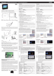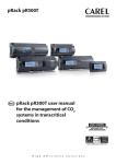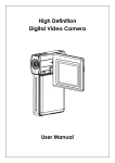
1
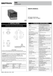
+0500038IE - rel. 1.4 - 18.06.2013 pCO5+ Controllo elettronico programmabile / Electronic programmable control pCO5+ is a programmable microprocessor electronic controller developed by CAREL to offer numerous applications in the air conditioning and refrigeration industry and in the general HVAC/R sector. It can be connected over the pLAN to all controllers in the pCO system family and to terminals in the pGD line. The application, created in the 1Tool development environment, is loaded on the controllers through the pCOManager program, available at http://ksa. carel.com. See manual code +0300020EN, that can be downloaded from www.carel.com. DIMENSIONS (mm) 44 Medium 315 60 70 Buit-in driver 315 60 70 Large 315 60 70 Extralarge 315 60 70 - - 75 - - MODELLI (vedere listino per codici di acquisto ordinabili) MODELS (see the list price for purchase codes, that can be ordered) Codice Descrizione Classific. P+5********** Memoria 9MB+4MB storici Memoria Memoria 5MB+2MB P+3********** storici () P+5*****0**** Uscite digitali tutte a relè Tipo di uscita P+5*****1...6**** 1...6 uscite SSR a 24 V digitale P+5*****A...F**** 1...6 uscite SSR a 230 V P+5****0***** Standard BMS2 non optois. P+5****A***** FieldBus2 non optois. Connettività BMS2 optois. / FieldBus2 P+5****B***** non optoisolata BMS2 optoisolata / P+5****C***** FieldBus2 optoisolata P+5***0****** No porta USB Porta USB P+5***A****** Porta USB P+5******0*** Senza driver valvola Driver P+5******1*** 1 driver valvola CAREL valvola P+5******2*** 2 driver valvola CAREL P+5*******0** Senza terminale Terminale P+5*******E** Con terminale integrato P+5********S* Small P+5********M* Medium Taglia P+5********L* Large P+5********Z* Extralarge P+5*********0/1 Singolo - multiplo Imballo ()I modelli previsti sono P+3**B00*0(0,E)(S,M,L,Z)0 Code Description Classific. P+5********** 9MB+4MB memory log file 5MB+2MB memory log Memory P+3********** file () P+5*****0**** Digital outputs all relay Digital P+5*****1...6**** 1 to 6 SSR outputs, 24V output type P+5*****A...F**** 1 to 6 SSR outputs, 230V P+5****0***** Standard BMS2 not optois. P+5****A***** FieldBus2 not optois. Connectivity BMS2 optois. / FieldBus2 P+5****B***** not optoisolated BMS2 optoisolated / P+5****C***** FieldBus2 optoisolated P+5***0****** No USB port USB Port P+5***A****** USB port P+5******0*** without valve driver Driver valve P+5******1*** 1 CAREL driver valve P+5******2*** 2 CAREL driver valve P+5*******0** Without terminal Integrated P+5*******E** With terminal terminal P+5********S* Small P+5********M* Medium Size P+5********L* Large P+5********Z* Extralarge P+5*********0/1 Single - multiple Packaging ()The models provided are P+3**B00*0(0,E)(S,M,L,Z)0. Codice PGDE000* PGDT04000F*** PGDT0700F*** PCOS0WUC20 S90CONN00* Code PGDE000* PGDT04000F*** PGDT0700F*** PCOS0WUC20 S90CONN00* Descrizione Terminale utente PGDE Termin. utente pGD Touch 4,3” Term. utente pGD Touch 7” Modulo ultracap per pCO5+ built-in driver Cavo telefonico Description User terminal PGDE User terminal pGD Touch 4.3” User terminal pGD Touch 7” Ultracap module for pCO5+ built-in driver Telephone cable WARNING: separate as much as possible the probe and digital input signal cables from the cables carrying inductive loads and power cables to avoid possible electromagnetic disturbance. Never run power cables (including the electrical panel wiring) and signal cables in the same conduits. Disposal of the product: the appliance (or the product) must be disposed of separately in accordance with the local waste disposal legislation in force. NO POWER & SIGNAL CABLES TOGETHER READ CAREFULLY IN THE TEXT! Morsettiera con connettori maschio/femmina estraibili Sezione cavi min 0.5 mm2 - max 2.5 mm2 Orologio con batteria di serie, precisione 100 ppm Buzzer abilitabile da software, solo con terminale integrato Batteria Di tipo “bottone” al litio cod. CR2430 tensione 3 Vdc (dimen. 24x3 mm) Classe e struttura del software Classe A Categ. di immunità ai surge (CEI EN 61000-4-5) Categoria III Dispositivo non destinato ad essere tenuto in mano quando alimentato Ingressi / Uscite Ingressi/uscite universali: Ingressi analogici, Lmax = 30 m, numero massimo Small Medium/Built-in driver/Extralar. sonde NTC CAREL (-50T90°C; R/T 10 kΩ ±1% a 25°C), 5 8 NTC HT (0T150°C), PTC (600Ω...2200Ω), PT500 (-100T300°C), PT1000 (-100T400°C) sonde PT100 (-100T400°C) 2 3 (2 su U1...U5, 1 su U6...U8) 5 segnali 0...1 Vdc/0...10 Vdc (*) da sonde alimentate dal controllo segnali 0...1 Vdc/0...10 Vdc (*) alimentati esternamente 5 4 ingressi 0...20 mA /4...20 mA (*) da sonde alimentate dal controllo ingressi 0...20 mA /4...20 mA (*) 4 alimentati esternamente segnali 0...5 V (*) da sonde raziomet. alim. dal controllo 5 Precisione ingressi: ± 0,3 % f.s. Costante di tempo per ogni ingresso: 0,5 s Classificazione dei circuiti di misura (CEI EN 61010-1): categoria I 6 8 6: (max 4 su U1...U5, 3 su U6...U8) 7: (max 4 su U1...U5, 3 su U6...U8) 6 Large 10 max tot 10 Small 227,5 60 70 max tot 9 B Alimentazione Small, Medium, Large, Extralarge: utilizzare un trasformatore dedicato di sicurezza in classe 2 da 50 VA. Biult-in driver: utilizzare un trasformatore dedicato di sicurezza in classe II da 100 VA. Vac P (Vac) Vdc P (Vdc) Small 24 Vac (+10/-15%), 50/60 Hz, fusibile 45 VA 28...36 Vdc (-20/+10%) 30 W Medium esterno da 2,5 A T fusibile esterno da 2,5 A T Large Extralarge Biult-in driver 90 VA Non ammesso Attenz.: per la versione “pCO5+ built-in driver” sono obbligatori l’alimentazione in alternata e il collegamento del secondario del trasformatore a terra (G0 a terra). max tot 8 A B B - con porta USB e/o terminale integrato B - with USB port and/or built-in terminal B - con modulo ULTRACAP B - with ULTRACAP module Situaz. di inquinam. del dispos. di comando Classe secondo la protezione contro le scosse elettriche PTI dei materiali per isolamento Periodo delle sollec. elettr. delle parti isolanti Tipo azioni Tipo di disconnessione o microinterruzione Categoria di resistenza al calore e al fuoco Caratter. di invecchiamento (ore funzionam.) N.ro di cicli di manovra operazioni automatiche Tensione impulsiva nominale Caratteristiche elettriche: 45 110 A Grado di protezione max tot 7 PCO5+ con modulo Ultracap montato: -40T60°C Condizioni di immagazzinamento P+(3,5)*******0**(no terminale integrato): -40T70 °C, 90% UR non conden. (*) P+(3,5)*******E**(con terminale integrato): -20T60 °C, 90% UR non conden. (*) P+(3, 5)*******0**(no terminale integrato): -40T70 °C, 90% UR non condens. P+(3, 5)*******E**(con terminale integr.): -30T70 °C, 90% UR non condens. Mod. con porta USB e/o con modulo Ultracap: IP20 nel solo frontalino Mod. senza porta USB e senza modulo Ultracap: IP40 nel solo frontalino 2 da integrare su apparecchiature di Classe I e/o II nelle versioni senza driver valvola, classe I nelle versioni con driver valvola PCB: PTI 250 V; materiale di isolamento: PTI 175 lungo 1C; 1Y per le versioni a SSR microinterruzione Categoria D (UL94-V2) 80.000 100.000 (EN 60730-1); 30.000 (UL 60730) 2500 V max tot 5 DIMENSIONI (mm) (*) max tot 4 pCO5+ è un controllo elettronico programmabile a microprocessore sviluppato da CAREL per offrire molteplici applicazioni nel settore del condizionamento dell’aria, della refrigerazione e in generale del settore HVAC/R. Può essere collegato in rete pLAN a tutti i controlli della famiglia pCO sistema ed ai terminali della gamma pGD. Il programma applicativo, creato nell’ambiente di sviluppo 1Tool, è caricato sul controllo tramite il programma pCO Manager, disponibile sul sito http://ksa.carel.com. Vedere il man. cod. +0300020IT, scaricabile dal sito www.carel.com. 4 (2 su U1...U5, 1 su U6...U8, 1 su U9...U10) 6 10 6: (max 4 su U1...U5, 3 su U6...U8, 2 su U9...U10) 9: (max 4 su U1...U5, 3 su U6...U8, 2 su U9...U10) 6 Ingressi digitali non optois., Lmax = 30 m, n.ro max Small Medium/Built-in driver/Extralar. Large contatti puliti 5 8 10 ingressi digitali veloci: tipo: contatto pulito, corrente 2 4: (max 2 su U1...U5, max 2 su 6: (max 2 su U1...U5, max 2 su max: 10 mA, freq. max: 2kHz e risoluzione: ±1 Hz U6...U8) U6...U8, 2 su U9...U10) Attenzione: • prevedere per le sonde attive (0...1 V, 0...10 V, 0...20 mA, 4...20 mA) alimentate esternamente, per evitare di danneggiare irreparabilmente il controllo, adeguate misure di protezione di corrente, che deve essere mantenuta < 100 mA; le sonde raziometriche possono essere alimentate solo dal controllo; • all’accensione, gli ingressi/uscite universali rimangono cortocircuitati a GND per circa 500ms fino al termine della fase di configurazione. Uscite analogiche non optois. (n.ro max), Lmax = 30 m, Small Medium/Built-in driver/Extralar. 0...10 Vdc (*) (corrente massima 2 mA) 5 8 PWM (uscita 0/3.3 Vdc, corrente max 2 mA, frequenza: 5 8 2kHz asincrono, 100 Hz asincrono) Large 10 10 Alimentazione sonde e terminali +VDC per l’alimentazione di eventuali sonde attive è possibile utilizzare i 24/21 Vdc ± 10% (*) (P+5*/P+3*) disponibili al morsetto +VDC (J2). La corrente max erogabile è di 150 mA protetta contro i cortocircuiti. +5VREF per l’alimentazione delle sonde raziometriche 0...5 V utilizzare i 5 Vdc (*) (± 5%) disponibili al morsetto +5VREF (J24). La corrente massima erogabile è di 60 mA. Vterm P+3**********: 21 Vdc ± 10% (*); P+5**********: 24 Vdc ± 10% (*). Da impiegarsi per alimentare un terminale esterno in alternativa a quello connesso a J10, Pmax = 1,5 W Attenz.: se la lunghezza supera i 10 m prevedere un cavo schermato con schermo connesso a terra. In ogni caso la lunghezza massima consentita è 30 m. Note per ingressi digitali: • separare quanto più possibile i cavi delle sonde e degli ingressi digitali dai cavi dei carichi induttivi e di potenza per evitare possibili disturbi elettromagnetici. Non inserire mai nelle stesse canaline (comprese quelle dei quadri elettrici) cavi di potenza e cavi di segnale; • in caso di ingressi in tensione continua (24 Vdc) è indifferente collegare il + o il - al morsetto comune; • la portata del contatto esterno degli ingressi digitali deve essere almeno pari a 5 mA. Uscite analogiche (Y...) Tipo 0...10 V optoisolate su Y1, Y2, Y3, Y4, Y5, Y6 / a taglio di fase (PWM) optoisolate su Y3, Y4 (configurabili via softw.) Lmax 30 m Small/Medium/Built-in driver/Extralarge 4 Y1...Y4 a 0...10 V Numero max Large 6 Y1...Y6 a 0...10 V Alimentazione esterna 24 Vac (+10/-15%) o 28...36 Vdc (+10/-20%) su VG(+), VG0(-) (*) Precisione Y1...Y6 ± 2% fondo scala Risoluzione 8 bit Tempo di assestam. Y1...Y6 Da 1 s (slew rate 10 V/s) a 20 s (slew rate 0,5 V/s) selezionabile via SW Carico massimo 1 kΩ (10 mA) Avvertenze: • per lunghezze > 10 m si prescrive un cavo schermato con schermo connesso a terra; • ad un’uscita analogica optoisolata di tipo 0...10 Vdc si possono collegare in parallelo altre uscite dello stesso tipo, oppure una tensione esterna. La tensione risultante sarà quella maggiore. Non è garantito il corretto funzionamento nel caso si colleghino attuatori con ingresso in tensione; • alimentare le uscite analogiche VG-VG0 con la stessa tensione presente su G-G0: connettere G a VG e G0 a VG0. Questo è valido sia per alimentazioni in alternata sia in continua; nel caso di uscite a taglio di fase (PWM) si fa notare che il sincronismo (zero crossing) è prelevato da G/G0 e solo con alimentazione 24 Vac e non Vdc. Uscite digitali NO..., NC... Tipo: Nr. max Distanza isolamento Relè. Corrente minima di contatto: 50 mA. 8: SMALL; 13: MEDIUM/ BUILT-IN DRIVER; 18: LARGE; 29: EXTRALARGE Le uscite relè hanno caratteristiche diverse a seconda del modello del controllo. Le uscite sono suddivisibili in gruppi. I relè appartenenti ad uno stesso gruppo hanno tra loro iun isolamento di funzionamento e quindi devono essere sottoposti alla stessa tensione. Tra gruppo e gruppo vi è isolamento rinforzato quindi i relè possono essere sottoposti a tensioni diverse. In ogni caso tra ogni morsetto delle uscite digitali e il resto del controllo esiste il doppio isolamento. Per quanto riguarda l’isolamento tra gruppi di relè, il tipo di relè e la potenza commutabile vedere il manuale cod. +0300020IT. Per le caratteristiche delle uscite SSR vedere il manuale cod. +0300020IT. Modello con driver per valvola di espansione elettronica: vedere il manuale cod. +0300020IT. (*) classe 2. Technical characteristics Plastic case Installation Material Self-extinguishing Temperature for the ball pressure test Creeping current resistance Colour Built-in terminal Other specifications Operating conditions (*) with Ultracap module installed: -40T60°C Storage conditions Fitted on DIN rail as per DIN 43880 and IEC EN 50022 Technopolymers V2 (according to UL94) and 850 °C (according to IEC 60695) 125 °C ≥ 250 V White RAL 9016 Type PGD1 (132x64 pixel) with backlit keyboard P+(3,5)*******0**(no Built-in terminal): -40T70°C, 90% UR no-condensing (*) P+(3,5)*******E**(with Built-in terminal): -20T60 °C, 90% UR no-condensing P+(3, 5)*******0**(no Built-in terminal): -40T70 °C, 90% UR no-condensing P+(3, 5)*******E**(with Built-in terminal): -30T70 °C, 90% UR no-condensing Protection index Models with USB port and/or with Ultracap module: IP20 in the front panel only Models without USB port and without Ultracap module: IP40 in the front panel only Control pollution situation 2 Class according to protection against electrical to be integrated into Class I and/or II appliances in the versions without valve driver, shocks Class I in versions with valve driver PTI of the insulating materials PCB: PTI250; insulation material: PTI 175 Period of electrical stress on the insulat. parts Long Type of actions 1C; 1Y for SSR versions Type of disconnection or microswitching Micro-switching Category of resistance to heat and fire Category D (UL94-V2) Aging characteristics (operational hours) 80.000 Number of automatic operating cycles 100.000 (EN 60730-1); 30.000 (UL 60730) Rated impulse voltage 2500 V Electrical characteristics Power supply Small, Medium, Large, Extralarge: use a dedicated safety transformer rated in Class 2 from 50 VA. Biult-in driver: use a dedicated safety transformer rated in Class II type 100 VA. Vac P (Vac) Vdc P (Vdc) Small 24 Vac (+10/-15%), 50/60 Hz, external 45 VA 28...36 (-20/+10%) Vdc 30 W Medium fuse from 2.5 A T external fuse type 2.5 A T Large Extralarge Biult-in driver 90 VA Not allowed Atten.: the pCO5+ with built-in driver must be powered with alternating current and the secondary winding of the power supply transformer (G0) must be earthed. Terminal block with male/female plug-in connectors, Cable section min 0.5 mm2 - max 2.5 mm2 Clock with battery standard, precision 100 ppm Buzzer enabled by software, only with built-in terminal Battery Lithium “button” type code CR2430 voltage 3 Vdc (dimensions 24x3 mm) Software class and structure Class A Surge protection category (CEI EN 61000-4-5) Category III Device not meant to be held in the hand when receiving power inputs 0...20 mA /4...20 mA (*) from probes powered by the control inputs 0...20 mA /4...20 mA (*) powered externally 4 4 6 signals 0...5 V (*) from raziom. probes pow. by control 5 Input precision: ± 0,3 % f.s. Time constant for each input: 0,5 s Classification of measuring circuits (CEI EN 61010-1): category I Digital inputs not opt.-isolated , Lmax = 30 m, max. num. free contacts fast digital inputs: type: free contact, max current: 10 mA, max freq.: 2kHz and resolution: ±1 Hz Attention: 6 8 max tot 10 5 5 Large 10 6: (max 4 su U1...U5, 3 su U6...U8) 7: (max 4 su U1...U5, 3 su U6...U8) max tot 9 DESCRIPTION DESCRIZIONE signals 0 ...1 Vdc/0 ...10 Vdc (*) from probes pow. by control signals 0...1 Vdc/0...10 Vdc (*) powered externally max tot 8 pGDE* agganciabile su guida DIN secondo DIN 43880 CEI EN 50022 tecnopolimero V2 (secondo UL94) e 850 °C (secondo IEC 60695) 125 °C ≥ 250 V Bianco RAL 9016 Tipo PGD1 (132x64 pixel) con tastiera retroilluminata nr. ingr. optoisol. a nr. ingr. optois. a 24 Vac o 230 Vac 24 Vac o 24 Vdc (50 Hz) Small 8 Nessuno Numero massimo Medium/Built-in driver/ Extralarge 12 2 Large 14 4 Tempo minimo di rilevazione Normalm. aperto (aperto-chiuso-aperto) 200 ms impulso agli ingressi digitali Normalm. chiuso (chiuso-aperto-chiuso) 400 ms IDH...: 230 Vac (+10/-15%) 50/60 Hz Alimentazione degli ingressi Esterna ID...: 24 Vac (+10/-15%) 50/60 Hz o 28...36 Vdc (-20/+10%) Classific. dei circuiti di misura Categoria I: 24 Vac/Vdc (J5, J7, J20); Categoria III: 230 Vac (J8, J19) (CEI EN 61010-1) Corrente assorbita ingressi digitali in tensione a 24 Vac/Vdc 5 mA Corrente assorbita ingressi digitali in tensione a 230 Vac 5 mA max tot 7 READ CAREFULLY IN THE TEXT! Contenitore plastico Montaggio Materiale Autoestinguenza Temperatura per la prova con la sfera Resistenza alle correnti striscianti Colore Terminale integrato Altre caratteristiche Condizioni di funzionamento max tot 5 Caratteristiche tecniche NO POWER & SIGNAL CABLES TOGETHER Inputs / Outputs Universal inputs/outputs: Analogue inputs, Lmax = 30m, maxim. number Small Medium/Built-in driver/Extralar. Probes: NTC CAREL (-50T90°C; R/T 10 kΩ ±1% 5 8 a 25°C), NTC HT (0T150°C), PTC (600Ω...2200Ω), PT500 (-100T300°C), PT1000 (-100T400°C) PT100 probes (-100T400°C) 2 3 (2 su U1...U5, 1 su U6...U8) max tot 4 Ingressi digitali - Uscite analogiche Ingressi digitali (ID... IDH...) Tipo Optoisolati Lmax 30 m 4 (2 su U1...U5, 1 su U6...U8, 1 su U9...U10) 6 10 6: (max 4 su U1...U5, 3 su U6...U8, 2 su U9...U10) 9: (max 4 su U1...U5, 3 su U6...U8, 2 su U9...U10) 6 Small Medium/Built-in driver/Extralar. Large 5 8 10 2 4: (max 2 su U1...U5, max 2 su 6: (max 2 su U1...U5, max U6...U8) 2 su U6...U8, 2 su U9...U10) • provide adequate current protection measures for externally powered active probes (0 to 1 V, 0 to 10 V, 0 to 20 mA, 4 to 20 mA), to prevent irreparable damage to the controller, which must be maintained at < 100 mA; the raziometric probes can be powered only by the controller; • at power on, universal inputs/outputs are short circuited to GND for about 500ms up to the end of the configuration. Anal. outputs not opt.-isolated (max. nu.), Lmax = 30 m Small Medium/Built-in driver/Extralar. 0...10 Vdc (*)(max current 2 mA) 5 8 PWM (output 0/3.3 Vdc, max. current 2 mA, frequency: 2kHz 5 8 asynchronous, 100 Hz asynchronous) Large 10 10 Probe and terminal power supply +VDC for supplying any active probes, the 24/21 Vdc ± 10% (*) (P+5*/P+3*) can be used, available to the +VDC (J2) terminal. The maximum deliverable current is 150 mA protected against short-circuits. +5VREF for supplying the 0 to 5 V raziometric probes, use the 5 Vdc (*) (± 5%) available to the +5VREF(J24) terminal. The maximum deliverable current is 60 mA. Vterm P+3**********: 21 Vdc ± 10% (*); P+5**********: 24 Vdc ± 10% (*) To be used to power an external terminal as an alternative to the one connected to J10, Pmax = 1.5 W Attent.: if the length exceeds 10m, provide a shielded cabled with the shield earthed. In any case, the maximum length permitted is 30 m. Note for digital inputs: • separate the probe and digital input cables as much as possible from inductive loads and power cables, to avoid any electromagnetic disturbances. Never lay power cables and signal cables in the same cable conduits (including those for electrical panels; • In the event of continuous voltage inputs (24 Vdc) it makes no difference whether the + or - is connected to the common terminal; • the capacity of the external contact of the digital inputs must be at least equal to 5 mA; Digital inputs - Analogue outputs Digital inputs (ID... IDH...) Type Optically-isolated Lmax 30 m Minimum digital input pulse detection time Small Medium/Built-in driver/ Extralarge Large Normally open (open-closed-open) Normally closed (closed-open-closed) Input power supply Esterna Maximum number no. opt.-isolated inputs no. opt.-isolated inputs at 24 Vac or at 24 Vac or 24 Vdc 230 Vac (50 Hz) 8 None 12 2 14 4 200 ms 400 ms IDH...: 230 Vac (+10/-15%) 50/60 Hz ID...: 24 Vac (+10/-15%) 50/60 Hz o 28...36 Vdc (-20/+10%) Classification of measuring Category I: 24 Vac/Vdc (J5, J7, J20); Category III: 230 Vac (J8, J19) circuits (CEI EN 61010-1): Absorbed current digital inputs at 24 Vac/Vdc 5 mA Absorbed current digital inputs at 230 Vac 5 mA Analogue outputs (Y...) Type 0...10 V optically-isolated on Y1, Y2, Y3, Y4, Y5, Y6 / at cut-off (PWM) opt.-isolated on Y3, Y4 (configurable by softw.) Lmax 30 m Small/Medium/Built-in driver/Extralarge 4 Y1...Y4 a 0...10 V Max number Large 6 Y1...Y6 a 0...10 V Power supply external 24 Vac (+10/-15%) o 28...36 Vdc (+10/-20%) su VG(+), VG0(-) (*) Precision Y1...Y6 ± 2% full scale Resolution 8 bit Settling time Y1...Y6 From 1 s (slew rate 10 V/s) a 20 s (slew rate 0,5 V/s) selectable by SW Maximum Load 1 kΩ (10 mA) Warnings: • lengths > 10 m require a shielded cable with the shield earthed; • other inputs of the same type or an external voltage can be connected in parallel to an optically-isolated analogue output type 0 to 10 Vdc. The resulting voltage is the higher one. Proper operation is not guaranteed if actuators with inputs under power are connected; • supply analogue VG-VG0 outputs with the same voltage present on G-G0; connect G to VG and G0 to VG0. This is valid for both alternating and continuous current; in the event of cut-off outputs (PWM) please note that synchronization (zero crossing) is taken from G/G0 and only with 24Vac and not Vdc. Digital outputs NO..., NC... Type: Nr. max Insulation distance Minimum relay contact current: 50 mA. 8: SMALL; 13: MEDIUM/ BUILT-IN DRIVER; 18: LARGE; 29: EXTRALARGE The relay outputs have different characteristics according to the controller model. The outputs can be divided into groups. The relays belonging to the same group have an operational insulation between them and thus must be subjected to the same voltage. Between one group and the other there is reinforced insulation, therefore the relays can be subjected to different voltages. In any case, between every terminal of the digital outputs and the rest of the controller there is double insulation. As for the insulation between groups of relays, the type of relay and switchable power see manual code +0300020EN. For the characterstics of the SSR outputs, see manual code +0300020EN. Model with driver for electronic expansion valve: see manual code +0300020EN. (*) class 2. 13 12 14 Esc Bianco Ritorno livello superiore UP Bianco • Premuto insieme a DOWN e ENTER permette di cambiare l’indirizzo del terminale (solo per terminali PGDE); • aumento valore Conferma valore Enter Bianco Enter White White DOWN White DOWN Bianco Sele- zione indirizzo pLAN • Premuto insieme a UP e ENTER permette di cambiare l’indirizzo del terminale (solo per terminali PGDE); • Diminuzione valore • Pressione breve: visualizzazione indirizzo pLAN • Pressione lunga (> 5s): procedura di modifica indirizzo pLAN pLAN address selection • Pressed together with UP and ENTER allows the terminal address to be changed (only for PGDE terminal); • decrease value • short press: shows pLAN address; • long press (> 5s): procedure for modifying the pLAN address CONFIGURAZIONE PORTA J26 Serial Ports Serial Type/connectors Specifications ZERO pLAN/J10, J11 Integrated on main board RS485 pLAN Not optically-isolated Connectors: 6-way telephone jack + 3-way removable p. 5.08 Max length: 500 m Maximum number of connected devices: 32 ONE BMS 1 Serial Card Not integrated on main board TWO FieldBus 1 Serial Not integrated on main board Card THREE BMS 2/ J25 Integrated on base card RS485 Slave Serial opt.isolated/not opto-isolated( *) 3-way removable connector 5.08 Maximum length: 1000 m FOUR FieldBus 2 / J26 Integrated on base card RS485 (and J23 on Large Master/Slave (**) and Extralarge J23: not optically-isolated , version) J26: opt.-isolated/not opt.-isolated 3-way removable connector 5.08 Note: use twisted pair shielded cable AWG 20-22 for the +/-; (*) available in 2 models; (**) J26 configurable PORT J26 CONFIGURATION Rispetto al pCO5, i controlli pCO5+ sono dotati di In comparison to pCO5, the pCO5+ controllers 4 microinterruttori per configurare la porta seriale are equipped with 4 micro-switches to configure J26 (figura): the serial port J26 (figure): • microinterruttori tutti “IN BASSO”: porta J26 • all micro-switches “DOWN”: port J26 set with impostata con hardware FieldBus; FieldBus hardware; • microinterruttori tutti “IN ALTO” : porta J26 • all micro-switches “UP”: port J26 set with BMS(*) impostata con hardware BMS(*); hardware; La configurazione di fabbrica è: porta FieldBus. The factory setting is; FieldBus port. (*) (*) La porta seriale rimane comunque la FieldBus2 The serial port, however, remains FieldBus2 at the a livello software all’interno software level inside the 1Tool BMS J26 dell’ambiente di programmazioprogramming environment. ne 1Tool. CAREL INDUSTRIES HQs Via dell’Industria, 11 - 35020 Brugine - Padova (Italy) Tel. (+39) 0499716611 – Fax (+39) 0499716600 – http://www.carel.com – e-mail: [email protected] 1 2 3 4 FieldBus pLAN network J11 pLAN J11 pLAN pCO5+ J25 BMS2 J26 FBus2 MASTER/SLAVE pCO5+ J11 pLAN J25 BMS2 J26 FBus2 MASTER/SLAVE Etich. U... Tipo di segnale Ingressi/uscite universali, configurabili via software come: Ingressi analogici: - sensori NTC , PTC, PT500, PT1000 - sensori PT100 - segnali 0...1 Vdc o 0...10 Vdc - segnali 0/4...20 mA - segnali 0...5 V per sonde raziometriche Ingressi digitali (non optoisolati): - contatti puliti (non optoisolati) - ingressi digitali veloci Uscite analogiche (non optoisolate): - segnali 0...10 Vdc - segnali PWM Y... Uscite analogiche 0...10 Vdc, uscite PWM ID... Ingresso digitale a 24 Vac o 28...36 Vdc ID...H Ingresso digitale a 230 Vac NO... Uscita a relè, contatto normalmente aperto NC... Uscita a relè, contatto normalmente chiuso C... Uscita a relè, comune Tx/Rx, GND Porta seriale J25 BMS2 J26 FBus2 MASTER/SLAVE INPUTS/ OUTPUTS LABEL ETICHETTAT. INGRESSI / USCITE I controlli pCO5+ si differenziano per la taglia e sono provvisti di ingressi e uscite e alimentazione alle sonde attive adatte per le varie applicazioni. Le caratteristiche che dipendono dalla taglia sono: • numero massimo e natura degli ingressi/uscite; • presenza o meno del display integrato; • presenza del driver integrato per valvola di espansione. pCO5+ The pCO5+ controllers are differentiated by their size and are equipped with inputs and outputs and active probe power supplies that are suitable for the various applications. The size-related characteristics are: • max. number and nature of the inputs/outputs; • whether or not it has an integrated display; • presence of the integrated driver for the expansion valve Label U... Signal type Universal inputs/outputs, configur. via software such as: Analogue inputs: - sensors NTC , PTC, PT500, PT1000 - sensors PT100 - signals 0 to 1 Vdc or 0 to 10 Vdc - signals 0/4 to 20 mA -signals 0 to 5 V for raziometric probes Digital inputs (not opto-isolated): - free contacts (not opto-isolated) - fast digital inputs Analogue outputs (not opto-isolated): - signals 0 to 10 Vdc -signals PWM Y... Analogue outputs 0 to 10 Vdc, PWM outputs ID... Digital inputs to 24 Vac or 28 to 36 Vdc ID...H Digital inputs to 230 Vac NO... Relay outputs, contact normally open NC... Relay outputs, contact normally closed C... Relay outputs, common Tx/Rx, GND Serial port NO13 C13 NC13 NO12 C12 NC12 C9 NO9 NO10 NO11 C9 C17 NO17 NO18 NO19 NO20 C17 NO8 C8 NC8 C14 NO14 NO15 NO16 C14 C21 NO21 NO22 NO23 NO24 C21 C25 NO25 NO26 NO27 NO28 NO29 C25 NC12 NO13 C13 NC13 NO12 C12 U9 GND U10 GND ID17 ID18 IDC17 U6 U7 U8 GND ID9 ID10 ID11 ID12 IDC9 ID13H ID13 IDC13 ID14 ID14H ID13H ID13 IDC13 ID14 ID14H 9 J8 COLLEGAMENTO TERMINALE CONNECTING THE TERMINAL Il controllo e il terminale sono connessi in rete pLAN. 1: controllo pCO singolo Nel collegamento del controllo al terminale occorre tener presente i seguenti vincoli: • la lunghezza totale della rete pLAN non deve superare i 500 m. Quindi se il terminale è stato remotato la lunghezza del cavo del terminale entra nel computo totale della lunghezza; • il cavo telefonico non schermato si può utilizzare per una lunghezza massima di 50 m. Oltre questa lunghezza utilizzare un cavo schermato tripolare; • oltre i 200 m l’alimentazione del terminale deve essere fornita separatamente; • è possibile collegare al massimo 3 terminali allo stesso controllo pCO. I terminali devono essere dello stesso tipo (es. tutti PGD1). 1 terminale è alimentato dal controllo, gli altri due sono alimentati esternamente; • tranne PGD0/ PGD1/PGDE gli altri terminali vanno alimentati con alimentazione separata. CONNECTING THE TERMINAL The controller and terminal are connect in the pLAN network 1: pCO single controller In connecting the controller to the terminal, the following requirements must be applied: • the total length of the pLAN network must not exceed 500m. Therefore, if the terminal is remote, the length of the cable from the terminal is part of the total length computation; • unshielded telephone cable can be used for a max. length of 50m. If this length is exceeded, us a tri-polar shielded cable; • over 200 m, power supply must be provided separately to the terminal; • a max. of 3 terminals can be connected to the same pCO controller The terminals must be of the same type (e.g., type PGD1). 1 terminal is supplied by the controller, the other two are externally powered. • except for PGD1/PGD1/PGDE, the other terminals are powered separately. 2: Controllo pCO in rete pLAN Nel caso di terminale connesso ad un controllo pCO, a sua volta collegato in rete pLAN ad altri controlli, il terminale è alimentato direttamente dal controllo. Prestare attenzione per evitare che una doppia alimentazione raggiunga il terminale. A questo scopo impostare i ponticelli J14 e J15 della scheda TCONN6J000, tramite i quali è possibile interrompere il passaggio della corrente di alimentazione. 2: pCO controller in pLAN network In the case of a terminal connected to a pCO controller which is then connected to other controllers in the pLAN network, the terminal is supplied directly by the controller. Pay close attention to prevent the terminal from receiving a double power supply. For this purpose, set jumpers J14 and J15 on the TCONN6J000 card, through which the passage of the power supply can be interrupted Impostazione indirizzo pLAN pLAN address setup Procedura: Procedure: 1. premere per 5 s il tasto A. 1. press key A for 5 seconds. L’indirizzo pLAN inizierà a The pLAN address will start lampeggiare; to flash; 2. premere ripetutamente 2. press the key repeatedly o tenere premuto il Bus card BMS card or hold it down until tasto fino a raggiungere the desired address is l’indirizzo desiderato J4 J5 J3 reached (e.g., 7); remove (es. 7); estrarre il cacciavite; the screwdriver; 3. attendere finché l’indirizzo 3. wait until the address comincia a lampeggiare starts to flash quickly. In velocemente. In questa fase l’indirizzo è this phase the address is memorizzato ma non ancora attivo per il saved but it is not yet active in the program; programma applicativo; 4. remove power from the controller; 4. togliere alimentazione al controllo; 5. ridare alimentazione al controllo. Ora l’indirizzo 5. return power to the controller; The address is now active è attivato. Impostazione dell’indirizzo del terminale e connessione controllo-terminale Dopo aver impostato l’indirizzo del controllo (vedere paragrafo precedente), per stabilire la connessione controllo-terminale occorre impostare l’indirizzo del terminale. Seguire la procedura descritta nel manuale d’uso cod. +03000020IT. ID5 DI2 DI1 S4 • Pressed together with DOWN and ENTER allows the terminal address to be changed (only for PGDE terminal); • increase value confirm value Porte seriali Seriale Tipo/connettori Caratteristiche ZERO pLAN/J10, J11 Integrata su scheda base RS485 pLAN Non optoisolata Connettori: Jack telefonico 6 vie + Estraibili 3 vie p. 5,08 Lunghezza massima: 500 m Numero massimo dispositivi collegabili: 32 UNO BMS 1 Serial Non integrata su scheda base Card DUE FieldBus 1 Serial Non integrata su scheda base Card TRE BMS 2/ J25 Integrata su scheda base RS485 Slave Seriale optoisolata/non optoisolata(*) Connettore estraibile 3 vie p. 5,08 Lunghezza massima: 1000 m QUATTRO FieldBus 2 / J26 Integrata su scheda base RS485 (e J23 su Master/Slave (**) versione Large e J23: non optoisolata, Extralarge) J26: optoisolata/non optoisolata Connettore estraibile 3 vie p. 5,08 Nota: utilizzare cavo schermato AWG 20-22 a coppie twistate per i +/-; (*) disponibili i 2 modelli; (**) J26 configurabile 8 ID4 SLAVE 3 9 ID3 J25 BMS2 J26 FBus2 J7 J6 J8 Y4 SLAVE MASTER J8 J25 BMS2 J26 FBus2 J20 ID2 ID17 ID14H J26 FBus2 pCO5+ Y5 Y6 ID15H ID15 IDC15 ID16 ID16H ID13H ID13 IDC3 ID14 ID14H J11 pLAN 8 Tx/Rx GND 19 J19 ID1 GND ID14 pCO5+ C16 NO16 NO17 NO18 C16 NO14 C14 NC14 NO15 C15 NC15 DI1 DI2 GND VREF S1 S2 S3 S4 U6 U7 U8 GND ID9 ID10 ID11 ID12 IDC9 MASTER - SLAVE network 3 J18 J23 FBus2 15 Y3 U10 IDC13 pCO5+ J25 BMS2 IDC17 GND ID13 ID18 U9 Y6 Y5 connessioni in alternativa/ alternative connections J11 pLAN ID13H IDC9 ID12 GND In the pCO5+ there are three types of serials: pLAN, FieldBus and BMS. The RS485 Fieldbus port has Master type hardware while the RS485 BMS port has Slave type hardware. The protocols to be used on the RS485 Fieldbus port are, due to the nature of the port itself, Master type (Carel Master or Modbus RTU Master), even if Slave type (Carel Slave or Modbus RTU Slave) can be used in certain cases with the appropriate expedients. Similarly, on the RS485 BMS port, the protocols to be used are Slave type, even if with the appropriate expedients, Master-type protocols are possible. Note: the pLAN network is multi-master: each controller can be Master or Slave at the same time. J11 pLAN J7 ID11 9 J17 15 Y2 PC MASTER J23 FBus2 J20 ID10 J6 U7 U6 ID16 IDC15 ID15H ID15 IDC1 ID8 ID7 ID6 ID5 ID4 ID3 ID2 ID1 Y4 Y3 Y1 VG0 VG GND U5 GND J19 J5 Y2 J4 J3 U4 +VDC GND U3 U2 J2 U1 +5 VREF J24 GND G0 G +Vterm J1 B M S car d 8 J7 J22 J21 15 J20 J6 J16 8 Y1 C13 J18 NC13 NO13 NC12 C9 C12 NO12 J17 J22 J8 NETWORK CONNECTION BETWEEN CONTROLLERS Nel pCO5+ ci sono tre tipi di seriali: pLAN, FieldBus, BMS. La porta seriale Fieldbus RS485 ha hardware di tipo Master, mentre la porta seriale BMS RS485 ha hardware di tipo Slave. I protocolli da utilizzare sulla porta Fieldbus RS485 sono, per natura stessa della porta, di tipo Master (Carel Master o Modbus RTU Master), anche se possono essere utilizzati in casi particolari quelli di tipo Slave (Carel Slave o Modbus RTU Slave), con i dovuti accorgimenti. Analogamente sulla porta BMS RS485, i protocolli da utilizzare sono di tipo Slave, anche se con i dovuti accorgimenti è possibile avere protocolli di tipo Master. Nota: la rete pLAN è multi-master: ogni controllo può essere contemporaneamente Master o Slave. C16 NO9 NO11 NO10 C16 NO17 NO18 J16 J21 NO16 C9 C8 NC8 NO8 J15 NC15 1 C14 2 NO14 3 C15 J14 4 NC14 J13 C7 C7 C4 NO7 C4 NO6 C1 NO5 NO4 C1 NO3 NO2 J12 3 9 CONNESSIONE IN RETE TRA CONTROLLI In comparison to the pCO3, the pCO5+ (and pCO5) controllers have a second BMS serial port on the J25 connector (BMS2) and a second FieldBus port on the J26 connector (FBus2). In the pCO5+ cards, version Large and Extralarge, the J23 is also present and is labeled FBus2 as for connector J26. From the point of view of the 1Tool application management, it is, in fact, the same serial line and different addresses must be used for the devices connected to the 2 connectors, while from the electrical point of view, the ports are independent (an electrical failure on port J26 does not effect J23). See the technical characterist. table. Rispetto al pCO3, i controlli pCO5+ (e pCO5) possiedono una seconda porta seriale BMS sul connettore J25 (BMS2) e una seconda porta FieldBus sul connettore J26 (FBus2). Nelle schede pCO5+ versione Large e Extralarge è ancora presente il connettore J23 e riporta la scritta FBus2 come per il connettore J26. Dal punto di vista della gestione da applicativo 1Tool si tratta infatti della stessa linea seriale e si devono usare indirizzi diversi per i dispositivi connessi ai 2 connettori, mentre dal punto di vista elettrico le porte sono indipendenti (un guasto elettrico nella porta J26 non influenza la porta J23). Vedere la tab. caratteristiche tecniche. J7 J15 VG0 SERIAL PORTS 8 C9 NO9 NO10 NO11 C9 NO8 C8 NC8 NO13 C13 NC13 NO12 C12 NC12 C9 NO9 NO10 NO11 C9 NO13 C13 NC13 NO12 C12 NC12 NO8 C8 NC8 3 8 J6 J8 ID14H ID14 IDC13 S2 S3 Descriz. Backlight Functions Alarm White/ • Pressed together with UP Red and supplying power allows the controller address to be changed; • pressed together with Enter accesses the BIOS page Prg White/ Yellow Esc White return high level UP J19 3 VG Key VBAT G0 G 7 6 J7 19 7 GND 5 J6 15 9 23 AB CD N.O. Model 15 1 Tx/Rx GND U5 Tasto Descriz. Retro-illum. Funzioni Alarm Bianco/ • Premuto insieme a UP Rosso fornendo alimentazione permette di cambiare l’indirizzo del controllo; • premuto insieme a Enter permette di accedere alle maschere gestite da BIOS Prg Bianco/ Giallo KEYBOARD (BUILT-IN and PGDE) 15 J23 FBus2 GND TASTIERA (BUILT-IN e PGDE) 21 J22 U4 3 4 PORTE SERIALI IDC17 ID18 ID17 GND U10 U9 GND ID13 IDC9 ID13H VREF only model with built-in driver EXTRALARGE N.C. Model +VDC 3 J5 ID13H ID13 IDC13 ID14 ID14H J4 NO15 2 J3 VG VG0 Y1 Y2 Y3 Y4 ID1 ID2 ID3 ID4 ID5 ID6 ID7 ID8 IDC1 +Vterm GND +5VREF 1 J2 J25 BMS2 J26 FBus2 J29 S1 G AB CD GND ID12 ID11 ID10 ID9 GND U7 U6 U8 G0 J30 VBAT Y6 Y5 ID16H ID16 IDC15 ID15H ID15 IDC1 ID8 ID7 A BD 20 24 J30 B M S card U1 U2 U3 GND +VDC U4 GND U5 GND G G0 J24 J1 J8 J7 J21 driver U6 U7 U8 GND ID9 ID10 ID11 ID12 IDC9 FieldBus card J10 J20 J6 ID6 ID5 ID4 ID3 ID2 Y4 ID1 Y3 J5 Y2 Y1 VG0 VG J4 GND U5 GND U4 +VDC J3 GND U3 U2 J2 U1 +5 VREF J24 GND G0 +Vterm G J1 J19 J15 J28 18 ONLY FOR LARGE AND EXTRALARGE MODELS B M S card J18 J29 FieldB us car d C J17 J27 22 G FieldBus card J22 J18 U6 U7 U8 GND ID9 ID10 ID11 ID12 IDC9 17 ID9 H 43 21 Tx/Rx GND 16 J23 Fus2 E F J16 J18 J25 BMS2 J26 FBus2 C16 NO18 J22 J17 J16 1 3 2 4 Tx/Rx GND J15 1 3 2 4 J10 ID16H J26 FBus2 NO17 C16 J21 NO16 NC15 C15 NO15 C14 1 NC14 2 J14 J13 C9 NO9 NO10 NO11 C9 J12 J11 pLAN C7 NO7 C7 Tx/Rx GND C4 NO4 NO5 NO6 C4 C1 NO1 NO2 NO3 C1 + U8 J25 BMS2 3 NO14 4 15 J17 J11 pLAN J10 15 LARGE BUILT - IN DRIVER 15 15 J16 NO1 J18 11 NC13 J17 C13 C12 NC12 NO12 C9 NO13 1 4 J16 J15 NO11 C9 NO9 C8 J28 NO10 J14 J13 NC8 C7 NO8 C7 C4 NO7 C4 NO6 NO5 C1 J12 J11 pLAN NO4 NO3 C1 NO2 NO1 J27 2 A pLAN address selection key B pLAN (*) address display C Power supply presence LED D Overcharge LED E FieldBus/BMS on port J26 micro-switch (*) F USB Host (master) Port (*) G USB Slave (device) port (*) H Main Display (*) available in P+5... models, not available in P+3... models 3 A Tasto selezione indirizzo pLAN B Display indirizzo pLAN (*) C LED presenza alimentazione D LED sovraccarico E Microinterruttori FieldBus/BMS su porta J26 (*) F Porta USB Host (master) (*) G Porta USB Device (slave) (*) H Display principale (*) presente nei modelli P+5..., non nei modelli P+3... 1 Structure 4 Struttura 2 1 Power supply connectors [G(+), G0(-)] +Vterm: additional terminal power supply 2 +5 VREF power supply for raziometric probes 3 Universal inputs/outputs 4 +VDC: power supply for active probes 5 pLAN address setup key, secondary display, LED VG: power supply at voltage A (*) for optoisolat. analog.output 6 VG0: power supply for optoisolat. analogue output at 0 Vac/Vdc 7 Analog outputs 8 ID: digital inputs at voltage A (*) ID..: digital inputs at voltage A (*) 9 IDH..: digital inputs at voltage B (**) pLAN telephone connector for terminal/download 10 application programme 11 pLAN removable connector 12, 13, 14: Reserved 15 Relay digital outputs 16 BMS2 connector 17 FieldBus2 connector 18 FieldBus/BMS selector micro-switch 19 FieldBus2 connector 20 Electronic Valve A connector 21 Electronic Valve B connector 22 Connector for external Ultracap module 23 External driver analogue and digital inputs 24 Valve status signal LED (*) Voltage A: 24 Vac or 28 to 36 Vdc (*) Voltage B: 230 Vac - 50/60 Hz 3 1 Connettore per l’alimentazione [G(+), G0(-)] +Vterm: alimentazione per terminale aggiuntivo 2 +5 VREF alimentazione per sonde raziometriche 3 Ingressi/uscite universali 4 +VDC: alimentazione per sonde attive 5 Tasto impostazione indiriz. pLAN, display secondario, LED VG: aliment. a tensione A (*) per uscita analogica optois. 6 VG0: aliment. per uscita analogica optoisolata a 0 Vac/Vdc 7 Uscite analogiche 8 ID: ingressi digitali a tensione A (*) ID..: ingressi digitali a tensione A (*) 9 IDH..: ingressi digitali a tensione B (**) Connettore telefonico pLAN per terminale/ download 10 programma applicativo 11 Connettore estraibile pLAN 12, 13, 14: Riservato 15 Uscite digitali a relè 16 Connettore BMS2 17 Connettore FieldBus2 18 Microinterruttori selezione FieldBus/ BMS 19 Connettore FieldBus2 20 Connettore valvola elettronica A 21 Connettore valvola elettronica B 22 Connettore per modulo Ultracap esterno 23 Ingressi analogici e digitali driver esterno 24 LED segnalazione stato valvola (*) Tensione A: 24 Vac o 28...36 Vdc (**) Tensione B: 230 Vac - 50/60 Hz only model with built-in driver MEDIUM SMALL 10 C16 NC16 NC17 NC18 C16 CONNECTION TERMINALS MORSETTI DI COLLEGAMENTO Setting the terminal address and controllerterminal connection After having set the controller address (see the previous paragraph), in order to establish the controller-terminal connection, the terminal address must be set. Follow the procedure described in user manual code +03000020EN. IMPORTANT WARNINGS: The CAREL product is a state-of-the-art product, whose operation is specified in the technical documentation supplied with the product or can be downloaded, even prior to purchase, from the website www.carel.com. - The client (builder, developer or installer of the final equipment) assumes every responsibility and risk relating to the phase of configuration the product in order to reach the expected results in relation to the specific final installation and/or equipment. The lack of such phase of study, which is requested/indicated in the user manual, can cause the final product to malfunction of which CAREL can not be held responsible. The final client must use the product only in the manner described in the documentation related to the product itself. The liability of CAREL in relation to its own product is regulated by CAREL’s general contract conditions edited on the website www. carel.com and/or by specific agreements with clients. CAREL reserves the right to modify the features of its products without prior notice. +0500038IE - rel. 1.4 - 18.06.2013