1
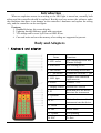
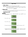
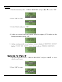
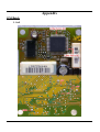
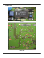
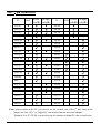
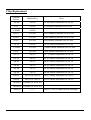
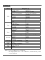
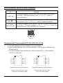
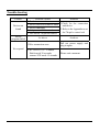
www.efichip.com
Applicable Vehicles for Airbag Resetting
Manufacturer
HONDA
Models
Remark
Accord 2.2 (CD5)
Accord 2.3
2002 Accord 2.4
Odyssey
CRV
SV4-A91
SV4-A92
SV4-A93
S84-A84
S84-A86
S3N-N93
SXO-A84
Y614
Y615
Y630
TOYOTA
2002 Camry
2002 Camry 2.4
VC-52180
VZ-52180
33100
33260
52120
60110
NISSAN
Cefiro 2001
Bluebird
209M000
Non-standard IC
www.efichip.com
7M806
A33
3L400
3L405
4Y715
MITSUBISHI
Sunny
Non-standard IC
Paladin
Non-standard IC
MB942715
268157
268154
942715
Outlander
Pajero Sport (MR587804)
HYUNDAI
ELANTRA
SONATA.
VW
JETTA
SANTANA
AUDI
GOL
GOLF
VW3/VW5/VW6
airbags reset by
PASSAT
Superb
Octavia
Fabia
BORA
POLO
GM
GL8
Regal
Excelle
K-line or OBD-II line
www.efichip.com
SAIL
MAZDA
B30E57K30B
M6(Double)
M6(GJ6a57K30c, 6 airbags)
Premacy (C17657K30b)
FORD
MONDEO
Resetting Vehicles not Listed
This is a very important feature! There are so many airbag models in the world that it is impossible to get
airbag data for all airbag models. With this function, user can perform airbag resetting for most vehicles
not listed in the above table by the following simple steps. This function is applicable to vehicles use chip
model 93C46, 93C56, 93C66, 24C01A, 24C04, 24C08, 25160, 25320, 95080, and
nonstandard 93C46.
1.To reset an airbag not listed in the above table, you just need to find a good airbag with same
type;
2.Install the good airbag chip onto the adapter, and connect the adapter to this item;
3.Select chip type and press F1 key. This item will read and save the data of the good airbag chip
automatically;
4.Take out the good airbag chip and insert the crashed airbag chip onto the adapter, and then
press F2 key. This item will write the stored data into the crashed airbag chip automatically.
User's Manual Download
To have a good understanding of this item, please download the PDF File User's Manual
Contents
Ⅰ.Introduction
………………………………………… (1)
Ⅱ.Body and Adapters …………………………………… (1)
Ⅲ.Operation Instruction
………………………………… (3)
1. Installation ………………………………………… (3)
………………………………………… (3)
2. Operation
2-1. CPU …………………………………………… (3)
2-2. 8-Pin IC
……………………………………… (4)
2-3. How to reset the airbags not listed …………… (5)
3. Updating
Ⅳ.Appendix
………………………………………… (6)
…………………………………………… (7)
1. GM airbags hookup
……………………………… (7)
2. VW airbags hookup
……………………………… (9)
3. Hyundai Elantra airbag hookup …………………… (10)
4. the 7th pin connection
5. IC replacement
…………………………… (11)
…………………………………… (12)
6. Vehicles & airbags available ……………………… (13)
7. How to remove and weld the device ……………… (14)
8. Identify the device pin’s sequence ………………… (15)
9. Standard and Non-standard IC C46
10. Trouble shooting
……………… (15)
………………………………… (16)
Ⅴ.Additional Function (IMMO READ CODE)…………… (17)
Attention
Insert the adapter first then connect the
power supply!
Do not pull out or insert the adapter and
device when power on!
Never weld device on the adapter when
power on!
·0·
Introduction
When an explosion occurs in an airbag or the SRS light is turned on, normally both
airbag and the controller should be replaced. But this tool can restore the software under
the conditions that there is no damage to the controller’s hardware and replace the airbag
only, and the controller can be used again.
Features:
1. Handhold design, big screen display.
2. Updating through Internet, quick and convenient.
3. VW airbags can be reset by K-line or OBD-II line.
4. Can read/write and save the memory of an airbag not supported at present.
Body and Adapters
Ⅰ.Keyboard and adapter
Items
Functions
1. CPU socket
For connecting Buick and
Elantra Airbags
2. SMD area
For welding device
3. DIP socket
For inserting device into
th
4. 7 pin socket
5. LED light
Control the volt of the 7th pin
Adapter well connected
light turns on
6. Power
Connect +12V
7. Display screen
Version No. 041020
8. F1
Read and save the device
data into the instrument
9. Upwards
10. F2
Write the data stored in the
instrument into the device
11. Down
12. OK
Select items
13. Update
For updating
14. ESC
To Exit
·1·
Ⅱ. Adapters
Very Important:
Insert the adapter first then connect the power supply!
Do not pull out or insert the adapter and device when power on!
Never weld device on the adapter when power on!
1. Be used to connect instrument and airbag controller (or its device).
2. Different connections due to different devices
Devices
Vehicles
Adapter
used
8-pin IC
Toyota, Honda,
Nissan, Cefiro,
Mazda, Mitsubishi
Universal adapter
Insert or weld the
Connection device into the
universal adapter
CPU
GM Buick, Elantra
Volkswagen
Universal adapter
1. Adapter for VW
2. OBD-II line
Solder on circuit board
and connect with CPU
socket as the hookup
attached shown
1. Controller removed from
cars reset by K-line
2. Reset by OBD-II line
3. Universal adapter, updating line and the Adapter for VW connect to the instrument
in the same way.
4. Adapters:
Adapter for VW
·2·
Universal Adapter
OBD-II line
Operation
Ⅰ.Installation
Plug in to star the instrument, vehicles display after 2 seconds.
Important: different countries use different voltages, please note the power adapter it
used: the input volt should be 100~220V, frequency 50/60HZ; output
12V/1.5A; and should be
Ⅱ. Operations
For some restored airbags, they should be reset by trouble code decoder before it can
be use again. E.g. Volkswagen, GM Buick and Mazda.
Operation for CPU
Volkswagen
1. Start the instrument, select “AIRBAG RESETER” and press ▲or▼ to select
“VOLKSWAGEN”
2. Press “OK” to enter
3. Press “OK” to enter
4. Connect the airbag controller with K-line or OBD-II line then press “OK”.
5. Resetting needs several minutes, when it finished, “RESETTING SUCCESS”
display. If “CHIP NOT FOUND” displays, please refer to 《TROUBLE SHOOTING》.
·3·
GM Buick
1. Start the instrument, select “AIRBAG RESETER” and press ▲or▼ to select “GM”.
2. Press “OK” to enter
3. Select Vehicle and press “OK”
4. Solder on circuit board and connect with the adapter (CPU socket) as the
hookup shown then press “OK”.
5. Airbag resetting needs several minutes, when it finished, “RESETTING SUCCESS”
display. If “CHIP NOT FOUND” comes, please refer to《TROUBLE SHOOTING》.
Operation for 8-pin IC
1. Start the instrument, select “AIRBAG RESETER” and press ▲or▼ to select
vehicle, say Toyota.
2. Press “OK” to enter
·4·
3. Select airbag type (marked on the back of the controller) or vehicle. E.g.
select “VC-52180” and press “OK”.
4. Device the controller used displays. Remove it from board and put it into/onto
adapter then press “OK”.
5. When resetting finished, “RESETTING SUCCESS” displays.
If “CHIP NOT FOUND” displays, please refer to《TROUBLE SHOOTING》.
Resetting the airbag not listed
1. Resetting principle:
Write the original data from a good airbag controller into a crashed one. So to
reset an airbag not listed here, we need good airbag controllers.
Attention: The airbags type and the devices they used should be same. Check
them before resetting. If you are not sure to read/write the CPU
not supported, please contact the manufacturer.
2. Remove the device from the good controller then put it into/onto the adapter
and connect the adapter with instrument.
3. Start the instrument, select “AIRBAG RESETER” and select “DEVICE OPERATE”
4. Press “OK”
5. Select device type. Press “F1” to read and save the device data into the instrument.
·5·
6. Saving need several seconds. “SAVING SUCCESS” when saving completed.
7. Take the device out of adapter and put the device from a crashed controller into the
adapter then press “F2” to write the data saved in the instrument into the device.
8. Mount this device back onto the board after “ RESETTING SUCCESS”.
9. Error when reading and writing, refer to《TROUBLE SHOOTING》.
Ⅲ. Updating
1. Download update software from our website and install.
2. Connect the resetting tool to Internet.
3. Start the resetting tool and press “0” to update.
4. Click “Airbag Resetting Tool Update” on the desk, and select “Update from
Internet” and then “Airbag Resetting Tool”, click “Next” to update.
5. The resetting tool will display “ADDING MODEL” then “ADD MODEL OK”. When it turns
to vehicle screen, update finished.
6. If have problems when updating, please contact the manufacturer.
·6·
Appendix
GM Buick
1. Sail
·7·
2. Buick GL8
·8·
Volkswagen
Notice: Red wire of Adapter for VW connects to +12V; black to GND and the
blue one is the K-line.
·9·
Hyundai Elantra
·10·
The 7th pin connections
to low
to high
volt(低) volt(高)
√
√
to low to high
volt(低) volt(高)
√
IC
Null
93C06
√
93C14
√
√
√
24C08
√
93C46
√
√
√
24C16
√
24C64
√
√
93CS46
93LC46
√
√
√
IC
Null
24C04
24C44
√
C46M6
√
25010
√
S130
√
25020
√
25040
√
93C56
√
√
√
√
√
√
√
93CS66
93LC66
√
√
S220
93C66
√
√
93CS56
93LC56
√
√
√
√
25043
√
√
25045
√
√
X25043
√
√
X5043
√
√
X5045
√
√
25080
√
C66M6
√
25160
√
B58
√
25170
√
93C76
√
25320
√
93C86
√
25640
√
93LC86
√
59C11
√
24C01
√
85C72
√
24C01A
√
85C82
√
24C02
√
85C92
√
Note: when read/write the IC, you need to set the control volt of the 7th pin. Just put the
jumper on “low (低)” or “high(高)” side marked on the universal adapter.
Example: For IC 93C86, you need to put the jumper on high(高) side to read/write.
·11·
Chip Replacement
Original
Device
Replaced by
93C06
93C46
93C06 cannot substitute for 93C46
9314
93C46
9314 cannot substitute for 93C46
C46M6
93C46
DD72
93CS66
DD72 cannot substitute for 93CS66
DD82
93CS66
DD82 cannot substitute for 93CS66
S220
93CS66
S220 cannot substitute for 93CS66
93C56
93C66
93C56 cannot substitute for 93C66
C56M6
93CS66
C56M6 cannot substitute for 93CS66
CS56
93CS66
CS56 cannot substitute for 93CS66
85C72
24C16
85C72 cannot substitute for 24C16
85C82
24C16
85C82 cannot substitute for 24C16
24C01
24C16
24C01 cannot substitute for 24C16
24C02
24C16
24C02 cannot substitute for 24C16
24C04
24C16
24C04 cannot substitute for 24C16
24C08
24C16
24C08 cannot substitute for 24C16
D6253
24C16 (or 24C01)
D6253 cannot substitute for 24C16
D6254
24C16 (or 24C01)
D6254 cannot substitute for 24C16
·12·
PDH001
X2444P (or X24C44)
PDH004
X2444P (or X24C44)
X24C01
-------
Note
X24C01, 24C01 cannot use in exchange
Available for
Vehicles
Honda
Airbag or car type
Accord 2.2(CD5)
Accord 2.3
Accord 2.4
Odyssey-SXO-A84
GB-S84-A84 (Guangzhou)
GB-S84-S86 (Guangzhou)
CRV
SV4-A91
SV4-A92
S84-A84
SV4-A93
S84-A86
Y614
SXO-A84
Y615
S3N-N93
Y630
Toyota
Nissan
Mitsubishi
Camry (2002)
33100
Camry 2.4 (2002)
33260
VC-52180
52120
VZ-52180
60110
Cefiro (2001)
Bluebird (FENGSHEN)
209M000
3L400
7M806
3L405
A33
4Y715
Sunny (Non-standard IC)
Paladin (Non-standard IC)
MB942715
268154
268157
942715
Outlander
Volkswagen
Hyundai
GM
Mazda
Ford
Citroen
VW3/VW5/VW6 airbags
Polo
Sonata
Elantra
GL8, Regal, Excelle, SAIL
B30E57K30B, M6
Mondeo
Elysee
Note: 1. For GL8 and Regal, select “GM Buick”;
2. VW airbag controllers reset by K-line or OBD-II line; For Polo controller, you need
to remove the device.
·13·
How to remove and weld the device
Ⅰ.Welding preparation
1.Soldering Iron selection
Soldering iron must connect to reliable GND, If have no constant temperature
soldering iron, then select the soldering iron of 20W (heater inside) or iron of 25W
(heater outside); The inside one should be less than 25W, the outside should be less
than 30W.
2.Welding-aid selection
Use rosin as welding-aid substance, never use strong corrosive soldering tin paste, if
rosin has been carbonized & becomes black, replace it.
3.Soldering wire selection
Select rosin activated core wire with low melting point.
Ⅱ.Chip Dismounting
1.When removing DIP device, use a suction gun or suction pipe to clean welded tin.
Do not pull it by force.
2.When removing SMD device, smelt more rosin to the pins and use soldering iron to
heat the pins until the device gets entire loose, and then remove it. Do not pull it by
force.
3.Heating time should not be too long to avoid any damage to the chip.
4.The chip on board commonly protected by protecting lacquer, use soldering iron to
heat protecting lacquer at first (heat to 70-80℃), then remove the chip after the
protecting lacquer cleaned.
Ⅲ.Chip welding
1.Welding time should not be too long to avoid any damage to the chip
2.Soldering iron is easy oxidized in high temp for a long time, clean the head of the
soldering iron often to keep it clean.
3.Heat transferred by soldering tin when welding, put soldering iron head on chip will
do no good to welding.
4.The chip shall not be moved or quivered before welding concreting.
5.When welding SMD, weld two diagonally pins to fix chip first, then weld others.
·14·
How to identify the device pin’s sequence
IC
IC with a cut
IC with ●
IC with
character only
Method
Put chip as diagram shown below. The first left pin of the bottom
row is Pin 1. The pins sequence is P1, 2, 3, 4, 5, 6, 7, and 8 in
counterclockwise.
Put chip as diagram shown below. the pin near ● is Pin 1. The
pins sequence is P1, 2, 3, 4, 5, 6, 7, and 8 in counterclockwise.
Put chip as diagram shown below. The first left pin of the bottom
row is Pin 1. The pins sequence is P1, 2, 3, 4, 5, 6, 7, and 8 in
counterclockwise. (Pay attention to the character)
93C56
Standard and Non-standard 93C46, 93LC46, LC46
1. C46 has Standard and Non-standard, most are standard.
2. Non-standard ones are used in some controllers, such as Sunny, Bluebird and
Paladin and etc.
3. For Non-standard chips, should select “Device Operation”→“Non-standard
93C46” to read/write.
·15·
Trouble shooting
Failure
Device not
found
Device
program failed
No respond
·16·
Possible Causes
Solution
1. Bad wire connection
1.Check for the connection
2. Device not well welded or short
and device.
3. Device damaged
2. Refer to the Appendix to set
4. Adapter not well inserted
the 7th pin’s control volt
5. Volt for the 7th pin not correct
As above
As above
1.Wire connection error
Pull out power supply and
plug in again
2. In “CONNECTING”. Connect
Buick needs 30 seconds;
connect VW needs 15 seconds.
Please wait a moment.
Ⅴ.IMMO READ CODE
Operation
1. Remove the chip from board, then well weld/insert it onto/into the adapter.
2. Start the instrument, select “IMMO READ CODE” and press ▲or▼ to select a
vehicle, say AUDI A6/V6.
3. Press “OK” then the device used displays.
4. Press “OK” to read out the code (4-digit code).
5. If cannot read the code, please try with “AUDI A6/V6 back”.
Error Warning
1. CHIP NOT FOUND
Possible caused by: ① The chip selected is not with that on the adapter; ② Device not
well welded/inserted; ③ Adapter not well inserted; ④ Chip damaged.
2. INVALID CODE
Possible reasons: ① Model selected not correct; ② No code data in device or data lost.
Available for
AUDI A6/V6
AUDI A6/V6 back
AUDI A6/C5 D03
AUDI A6/C5 D04-D09
STA2000
POLO (6Q0920800)
PASSAT B5 1.8
PASSAT B5 1.8T
BORA (6A, 6B) (1J5920806B, 1J5920826A)
BORA (5A, 5B) (1J5920805B,1J5920825A)
·17·


![[The Title of Document Property show here]](http://vs1.manualzilla.com/store/data/005679617_1-26050dab619968a0ccd4ef0aac394c5d-150x150.png)