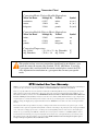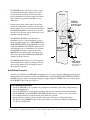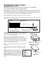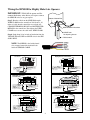
1
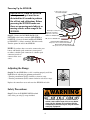
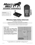
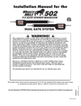
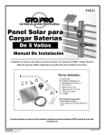
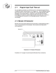
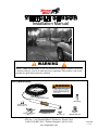
® VEHICLE SENSOR Installation Manual WARNING When a VEHICLE SENSOR is in use, the automatic gate opener could be activated by a child on a bicycle, tricycle or other metal play equipment. This product is not recommended for applications exposed to children. Parts Identification: ! WARNING WARNING GATE OPENING SENSOR IN USE The Automatic Gate Opener is activated when a vehicle comes within range of the sensor buried along side the driveway and could possibly be activated by a child on a bicycle, tricycle or other metal play equipment. SENSOR with 50 feet of Direct Burial Cable Double Spade Connectors (2) Battery Connection Wires (2) Warning Signs (2) Wire Clamp ! WA RNIN G Ty-Wraps (4) Wire Nuts (3) Range Adjustment Board GTO, Inc. • 3121 Hartsfield Road • Tallahassee, Florida 32303 1-800-543-GATE (4283) • Technical Support 1-800-543-1236 www.mightymule.com RWINSTMM rev-5/18/07 Thank You ... for purchasing the hands free VEHICLE SENSOR. This product requires no maintenance and will give you years of enjoyment by providing hands free operation of your gate. GTO, Inc., has been designing and manufacturing reliable, high quality products since 1987. Our corporate headquarters and state of the art manufacturing facility is located in Tallahassee, Florida. One of our highest priorities is to provide outstanding technical service to our customers. Therefore, if you have any questions or require any technical assistance, visit www.mightymule.com or call our toll free line 800-543-1236 for technical support. The VEHICLE SENSOR you have purchased is designed with some of the most advanced technology available. In layman’s terms, the sensor detects a change in the earths magnetic field caused by a mass of metal in motion and automatically opens your gate. The range adjustment potentiometer (POT) that connects to the control box provides you with the ability to increase or decrease the sensor’s sensitivity range. If a metal object is placed directly above the sensor (with little motion) it may cause the sensor to activate, thus opening your gate. For this reason we do not recommend the VEHICLE SENSOR in environments exposed to children. Prior to installing your Sensor please read the manual thoroughly. There are important safety recommendations of which you should be aware. This product, and any accessory you purchase, should only be installed on a gate opener that meets the current safety standard (UL325). If you have a gate opener that is not listed with the current standards, please contact the GTO sales department at 800-543-4283 or 850-575-0176 for consultation on a gate opener that can meet your specific needs. Joe Kelley, President of GTO, Inc. Contents Before You Start-----------------------------------------------------------------------page 1 Terms and Definitions:------------------------------------------------------------page 1 How the VEHICLE SENSOR works:-------------------------------------------page 1 How the Vehicle SENSOR’s RANGE ADJUSTMENT works:-------------page 1 Placement of the SENSOR:------------------------------------------------------page 2 Installation Overview:-------------------------------------------------------------page 2 Installing the VEHICLE SENSOR------------------------------------------------page 3 Determining SENSOR Location:------------------------------------------------page 3 Installing The WIRE CLAMP:---------------------------------------------------page 3 Wiring the SENSOR to the Mighty Mule Opener:-----------------------------page 4 Accessory Terminal Connection-------------------------------------------------page 4 Connecting the Range Adjustment Control Board:---------------------------page 5 Power Supply Connection:-------------------------------------------------------page 5 Powering up the SENSOR: ------------------------------------------------------page 6 Adjusting the Range: -------------------------------------------------------------page 6 Safety Precautions: ----------------------------------------------------------------page 6 Installation on other Brand Gate Openers---------------------------------------page 7 Technical Specifications--------------------------------------------------------------page 8 Trouble Shooting----------------------------------------------------------------------page 8 Other GTO Products-----------------------------------------------------------------page 9 Metric Conversion Chart & Warranty------------------------------ Inside Back Cover Conversion Chart Converting Metric Units to English Equivalents When You Know Multiply By To Find Symbol centimeters meters kilograms 0.3937 3.2808 2.2046 inches feet pounds in. (or “) ft. (or ‘) lb. (or #) Converting English Units to Metric Equivalents When You Know Multiply By To Find Symbol inches feet pounds 2.5400 0.3048 0.4535 centimeters meters kilograms cm m kg Converting Temperature deg. Celsius deg. Fahrenheit (ºC x 1.8) + 32 deg. Fahrenheit (ºF-32) ÷ 1.8 deg. Celsius ºF ºC This product and any accessory you purchase should only be installed on a gate opener that meets the current safety standard, UL325, 4th Edition. If you have a gate opener that is not listed with the current standard please contact the GTO sales department for consultation on a gate opener that can meet your specific needs. GTO Limited One Year Warranty: GTO, Inc., gate openers and accessories are warranted by the manufacturer against defects in materials and manufacturer workmanship for a period of one (1) year from date of purchase, provided the recommended installation procedures have been followed. In the case of product failure due to defective material or manufacturer workmanship within the one (1) year warranty period, the product will be repaired or replaced (at the manufacturer’s option) at no charge to the customer, if returned freight prepaid to GTO, Inc., 3121 Hartsfield Road, Tallahassee, Florida, USA 32303. IMPORTANT: Call (800) 543-1236 for a Return Goods Authorization (RGA) number before returning accessory to factory. Products received at the factory without an RGA number will not be accepted. Replacement or repaired parts are covered by this warranty for the remainder of the one (1) year warranty period or six (6) months, whichever is greater. GTO, Inc. will pay the shipping charges (equal to United Parcel Service GROUND rate) for return to the owner of items repaired under warranty. The manufacturer will not be responsible for any charges or damages incurred in the removal of the defective parts for repair, or for the reinstallation of those parts after repair. This warranty shall be considered void if damage to the product(s) was due to improper installation or use, connection to an improper power source, or if damage was caused by lightning, wind, fire, flood, insects or other natural agent. After the one (1) year warranty period, GTO, Inc. will make any necessary repairs for a nominal fee. Call GTO at (800) 543-1236 for more information. This warranty gives you specific legal rights, and you may also have other rights which may vary from state to state. This warranty is in lieu of all other warranties, expressed or implied. NOTE: Verification of the warranty period requires copies of receipts or other proof of purchase. Please retain these records. Before You Start ... Please read the instructions completely before you begin the installation. Terms and Definitions: • • • • • • • • METAL OBJECT: anything that is made of iron-based metal, from a child’s toy to a car or truck. SENSOR: the magnetic device inside the waterproof tube that detects METAL OBJECTS in motion. MAGNETIC FIELD: an area around the SENSOR where metal in motion can be detected. MAGNETIC DISTURBANCE: a change in the MAGNETIC FIELD which lets the SENSOR know that it needs to send a signal to the gate opener to open the gate. RANGE: the distance from the SENSOR in which a MAGNETIC DISTURBANCE can be detected in the MAGNETIC FIELD. RANGE ADJUSTMENT: the RANGE is adjustable from a 3 to 12 foot* radius by tuning the ADJUSTMENT POTENTIOMETER (POT) on the RANGE ADJUSTMENT CONTROL BOARD (shown on page 5). Within this RANGE, the closer you get to the SENSOR, the less metal and motion an object needs to cause a DISTURBANCE in the MAGNETIC FIELD. CAUTION This principle explains why a child’s tricycle, bicycle and other metal objects moving close to the SENSOR may have the same DISTURBANCE as a car or truck at a greater distance, and can cause the gate to open. WIRE CLAMP: a device which provides a secure and weatherproof opening for the cable from the SENSOR to be brought into a control box (see Parts Identification on cover). DOUBLE SPADE CONNECTOR: a wire connector which allows the connection of two wires to be connected to a single terminal (see Parts Identification on cover). How the VEHICLE SENSOR works: • • When a metal object such as a car, truck or motorcycle in motion disturbs the MAGNETIC FIELD around the SENSOR, a signal is sent to the automatic gate opener’s control board, signaling it to open the gate. The metal object must be in motion to disturb the MAGNETIC FIELD, thus activating the gate opener. How the VEHICLE SENSOR’s RANGE ADJUSTMENT works: • The RANGE distance can be adjusted from a 3 to 12 foot* radius from the SENSOR. • The potentiometer varies the sensitivity range of the SENSOR to avoid unwanted moving metal objects from activating the gate opener, such as: other moving gates; metal play equipment; garage doors; other vehicular traffic; etc. • With the RANGE adjusted to the maximum of 12 feet*, a large metal object moving slowly will be detected 12 feet* from the SENSOR, while a small metal object moving slowly might not be detected at the same distance. As you move closer toward the SENSOR, the small moving metal object will at some point cause a DISTURBANCE in the MAGNETIC FIELD and activate the gate opener. Placement of the SENSOR: * Range distance is approximate and will vary due to outside interference, type of soil, vehicle mass, speed, etc. 1 • • • • The SENSOR comes with 50 feet of cable. A typical installation will require about 5 feet of cable to come from the ground up and into the control box for connection to the power supply and control board. Check your specific installation for exact dimensions. Driveway SENSOR: 2 feet from driveway (max) and 12” deep From the point on the ground where you will run the Sensor cable into the control box, lay the cable out on a path as far as you can from the control box. The SENSOR should be no more than 2 feet from the edge of the driveway and no closer than 25 feet from the end of the open gate. RANGE: 12 ft. radius (max) 25 ft. from gate (min) The SENSOR’s RANGE can be adjusted to a maximum of 12 feet*. The movement of a gate in the open position could cause a DISTURBANCE in the MAGNETIC FIELD of the SENSOR if it comes within the RANGE of the SENSOR. Make sure the end of the open gate is a minimum of 25 feet from the SENSOR. If you have a situation where the SENSOR has to be buried closer than 25 feet you will need to adjust the RANGE of the SENSOR to compensate for the closeness. 45 ft. of Cable (max) Open Gate Outside Sensor Range The SENSOR must be buried 12” in soil to prevent direct sunlight from causing overheating. This also prevents large animals from activating the sensor due to physical vibrations. Gate Opener Control Box (Allow 5 ft for wiring to Control Box) Installation Overview: • Once the best location for the SENSOR is determined, you are ready to bury the SENSOR and run the cable underground to the control box. Connect the SENSOR wires and the RANGE ADJUSTMENT CONTROL BOARD to the gate opener control board and power supply. Adjust the RANGE if necessary. Finally, place the WARNING signs on the gate. That’s it! For Optimum Performance: • Locate the SENSOR as far as possible away from power transformers, power lines, underground gas line, and telephone lines. • Locate the SENSOR away from general moving traffic to prevent unwanted activation. Remember that the SENSOR detects MAGNETIC DISTURBANCES caused by a vehicle’s mass and velocity. • It is recommended that you run the Sensor cable inside PVC conduit. • Do not run Sensor cable in conduit with other wires such as AC power or other control wires. • The Sensor cable CANNOT be spliced. If you need more wire, contact the GTO Sales Department at 1-800-543-GATE (4283). * Range distance is approximate and will vary due to outside interference, type of soil, vehicle mass, speed, etc. 2 Installing the Vehicle Sensor ... Determining SENSOR Location: IMPORTANT: Clear an area 20 feet in all directions of metal tools, toys and automobiles, to prevent magnetic disturbance during testing and installation. Step 1: Determine the optimum location for the VEHICLE SENSOR using the information found in “Placement of the SENSOR” on page 2. Then dig a hole approximately 12 inches deep and 24 inches long within 2 feet and parallel to the edge of the driveway. Next, dig a trench approximately 12 inches deep from this hole to a spot under the gate opener control box to run the cable from the SENSOR to the control board. Keep the SENSOR and the cable uncovered at this time, but out of direct sunlight. We recommend that the cable be run in PVC conduit to the control box to prevent damage to the cable from lawn mowers, weed eaters and grazing animals. Gate opener control box Open gate outside sensor range Minimum of 25 feet Driveway 12” PVC conduit in ground and up to control box recommended SENSOR: 2 feet from driveway edge and 1 foot in ground Installing The WIRE CLAMP: The WIRE CLAMP (includ- 24” Mighty Mule FM700 & FM702 Control Box ed) is used to secure the sensor cable where it enters the control box to prevent it from being accidently pulled out. Step 2: If you are installing the SENSOR on a Mighty Mule FM700, FM500 and the FM502 gate openers, use a screwdriver or steel punch to carefully remove the thin plastic knockout disk (see illustrations at right) at the bottom of the control box. If you have a FM702 dual gate opener system, drill a 7/8” diameter hole at the bottom of the control box and install the WIRE CLAMP. Knockout Disk Drill 7/8" diameter hole for Dual Gate System Step 3: Use a sharp knife or deburring tool to clean the rough edges from the hole. WIRE CLAMP for Opener Power Cord Mighty Mule FM500 & FM502 Control Box Be careful with tools to avoid contact or damage to the control board! Wire Clamp Step 4: Unscrew and remove the lock nut from the WIRE CLAMP hub (included with hardware). From the outside of the control box, insert the WIRE CLAMP hub and sealing nut (see illustration right) into the new WIRE CLAMP hole. Finger tighten the lock nut onto the threaded end of the WIRE CLAMP hub from inside the box. 3 Lock Nut Hub Sealing Nut Knockout Disk WIRE CLAMP for Opener Power Cord Wiring the SENSOR to Mighty Mule Gate Openers: IMPORTANT: TURN OFF the power and dis- connect the battery wires before you begin to connect the SENSOR wires to any gate opener. Bottom of Control Box Step 5: Run the cable from the SENSOR through a WIRE CLAMP into the control box. Pull about 8 - 10 inches of cable into the control box to reach the ACCESSORY TERMINAL BLOCK and BATTERY TERMINALS in the control box. Now tighten the WIRE CLAMP nut to secure the cable in the WIRE CLAMP. WIRE CLAMP in Knockout CABLE from the Opening Sensor Step 6: Strip about 3/8 of an inch of insulation from the YELLOW, BLACK, RED and BLUE wires in the SENSOR CABLE. PVC Conduit NOTE: The SHIELD is the braided metal wire wrapped around the insulated leads inside the SENSOR CABLE. Mighty Mule 350 Control Board LEARN WHT BLU ORG GRN SEQ1 SEQ2 ON PRO-1000, PRO-SL1000 and Old Mighty Mule Control Boards R B G Connect the BLACK wire from the SENSOR CABLE to the GRN terminal on the opener control board. BLK RECR Connect the BLACK wire from the SENSOR CABLE to one of the COMMON terminals on the opener control board. Connect the BLUE wire from the SENSOR CABLE to the EXIT terminal on the opener control board. Connect BLUE wire from the SENSOR CABLE to the BLU terminal on the opener control board. RED GRN COMMON RCVR EDGE ACCESSORY CYCLE EXIT ALARM SAFETY LINK BLACK BLUE BLACK BLUE GEN-3 (Blue) Control Boards Mighty Mule 500 & 502 Control Boards RECEIVER RED Connect the BLACK wire from the SENSOR CABLE to one of the COMMON terminals on the opener control board. BLUE OPEN EDGE CLOSE EDGE SHADOW LOOP EXIT OPEN GRN BLK RED BLK RED BLUE SX4000 L COM COM COM COM COM STOP CLOSE OPEN RUN 2 SAFETY J12 CYCLE Connect the BLACK wire from the SENSOR CABLE to one of the COMMON terminals on the opener control board. CYCLE CLOSE COM SAFETY COM SHADOW LOOP COM GTO/PRO GP-SL100 and GP-SW100 Control Boards OPEN EDGE J8 GRN CLOSE EDGE OPEN EDGE SHADOW BLACK GTO/PRO DC Powered PRO-SW3000 and PRO-SW4000 Control Boards J11 GTO RCVR. Connect the BLUE wire from the SENSOR CABLE to the EXIT terminal on the opener control board. GTO Inc. BLACK EXIT COM Connect the BLUE wire from the SENSOR CABLE to the EXIT/OPEN terminal on the opener control board. SAFETY ALM RECEIVER COM OPEN EDGE GRN BLK CYCLE Connect the BLACK wire from the SENSOR CABLE to one of the COMMON terminals on the opener control board. CLOSE EDGE SHADOW LOOP EXIT/ OPEN SAFETY COM COM CYCLE CLOSE CONTROL INPUTS RECEIVER Connect the BLUE wire from the SENSOR CABLE to the OPEN terminal on the opener control board. Connect the BLUE wire from the SENSOR CABLE to the EXIT/OPEN terminal on the opener control board. BLACK BLUE Connect the BLACK wire from the SENSOR CABLE to one of the COMMON terminals on the opener control board. BLUE 4 BLACK Connecting the Range Adjustment Control Board: Step 9: Connect the YELLOW wire from the SENSOR CABLE to the YELLOW wire from the Range Adjustment control board using one of the WIRE NUTS provided. Step 10: Connect the BLACK wire from the Range Adjustment control board to the BLACK BATTERY CONNECTOR wire (provided), along with the SHIELD wire from the SENSOR CABLE (see Step 13 below). Range Adjustment Control Board Optional Mounting Hole Potentiometer (POT) MIN Wire Nut MAX Wire Nut Shield Wire BLACK BATTERY CONNECTORwire provided YELLOW BLACK YELLOW wire from SENSOR Cable Step 11: Secure the RANGE ADJUSTMENT CONTROL BOARD inside the gate opener control box. The control box has slots on both sides of the top battery compartment for extra control boards, or you can use the optional mounting hole. IMPORTANT: DO NOT let exposed wiring or components on the control board make contact with other exposed wiring or components. The Range Adjustment Control Board can be mounted in slots on either side of top battery compartment OR the mounting hole beneath battery compartment. The Range Adjustment Control Board can be mounted in the slot at the bottom OR the slot at the bottom right. Both are located beneath the circuit board. Mighty Mule FM500 & FM502 Control Box Mighty Mule FM700 & FM702 Control Box Power supply connection: Step 12: Connect the RED and BLACK control board wires from the opener to the DOUBLE SPADE CONNECTORS (provided) as shown on the next page. Step 13: Using a WIRE NUT, connect the SHIELD wire from the SENSOR CABLE (along with the BLACK wire from the Range Adjustment board) to the BLACK BATTERY CONNECTION wire provided. Using the remaining WIRE NUT connect the RED wire from the SENSOR CABLE to the RED BATTERY CONNECTION wire provided. Step 14: Connect these wires to the DOUBLE SPADE CONNECTORS as shown. IMPORTANT: Be sure to connect both RED leads to the same DOUBLE SPADE CONNECTOR and both BLACK leads to the other DOUBLE SPADE CONNECTOR. You will connect the DOUBLE SPADE CONNECTORS to the battery in the next step. 5 Powering Up the SENSOR: Double Spade Connectors included with SENSOR IMPORTANT: When the SENSOR is first powered up it must be undisturbed for 60 seconds to perform the self test and calibrations. Before powering the SENSOR make sure there are no moving metal objects or moving vehicles within range of the SENSOR. Step 15: Connect the DOUBLE SPADE CONNECTORS to the battery terminals (RED WIRES to POSITIVE (+) battery terminal and BLACK WIRES to NEGATIVE (–) battery terminal). Wait 60 seconds. Turn the opener on and test the SENSOR. RED Opener Battery Wire BLACK Opener Battery Wire BLACK wire from Range Adjustment control board SHIELD from SENSOR Cable RED wire from SENSOR Cable BLACK BATTERY CONNECTION Wire with Spade Connector included with SENSOR RED BATTERY CONNECTION Wire with Spade Connector included with SENSOR NOTE: If you have other accessories connected to your battery with double spade connectors you may need to connect a double spade connector to a double spade connector in order to connect all the accessories. Adjusting the Range: Step 16: Test the SENSOR to see if it is working properly and if the RANGE needs adjusting for optimum performance. • Turn the potentiometer (POT) clockwise to increase range. • Turn the potentiometer (POT) counter-clockwise to decrease range. MIN MAX Replace the control box cover and cover the SENSOR and cable. 8.5" Safety Precautions: Step 17: Place the WARNING SIGNS on both sides of the gate using Ty-wraps included. ! 4.38" WARNING GATE OPENING SENSOR IN USE The Automatic Gate Opener is activated when a vehicle comes within range of the sensor buried along side the driveway and could possibly be activated by a child on a bicycle, tricycle or other metal play equipment. REWWARN01 6 For Installation on Other Brand Gate Openers ... If you are using the VEHICLE SENSOR on any other automatic gate opener brand, use the information below for wiring the system. If you do not understand the instructions below, please call GTO’s Technical Support at 1-800-543-1236. Typical Gate Wiring Connection: • Reference Leads: oRED => Input Voltage (+) oSHIELD => Ground/Common (–) oBLACK => Relay’s Common oBLUE => Relay’s Normally Open oYELLOW => Remote SENSOR [Range adjustment potentiometer (POT)] • Terminology Definitions: o‘FREE EXIT/ENTRY’ is defined as input terminals (2) that upon activation (momentarily connected together) will cause the gate to run in the open direction only. Note: In most gate openers, one of the two terminals is the ‘COMMON/GND’. • Power supply connection: oDC power supply: (11-36 Vdc) ß Connect the positive (+) lead of the power supply to the RED wire. ß Connect the negative (-) lead of the power supply to the SHIELD wire. oAC power supply: (8-26 Vac) ß Connect the power supply to the RED & SHIELD wires. There is no polarity for AC power supply. • Relay output connection: oConnect the BLUE wire from the SENSOR to the ‘FREE EXIT/ENTRY’ of the gate opener. oConnect the BLACK wire from the SENSOR to the ‘COMMON/GND’ of the gate opener. • Range (POT) board connection: oConnect the YELLOW wire from the SENSOR to the YELLOW wire from the Range Adjustment Board. oConnect the BLACK wire from the Range Adjustment Board to a negative input voltage. oTurn the POT clockwise to increase range. oTurn the POT counter-clockwise to decrease range. Input Voltage 11 - 36 Vdc or 8 - 26 Vac Generic Wiring Diagram + Input Voltage (–) SHIELD Relay Output Common BLACK Relay Output Normally Open BLUE Range Adjustment YELLOW – Free Exit/Entry Connections BLACK RED YELLOW Input Voltage (+) Range Adjustment Board SENSOR 7 TECHNICAL SPECIFICATIONS: • Power supply: 8-26 Vac/dc. • Current consumption: 1.5 mA typical. • Relay rating: Latching relay. • • • • • Nominal switching capacity (resistive load) Max. switching power (resistive load) Max. switching voltage Max. switching current 1 Amp 30 Vdc, 0.5 Amp 125 Vac 30 Watt, 62.5 V A 110 Vdc, 125 Vac 1 Amp Relay Trip Time: 2 seconds. Operating Temperature: -25°F (-14°C) to 125°F (69°C). Dimensions: 1-3/4” (44.5 mm) diameter x 16.5” (42 cm) long. Adjustable range: 3 -12 feet typical installation. Very low power consumption, ideal for battery application. Troubleshooting: Make sure all connections are correct. If the SENSOR is not working: 1. Make sure the Range Adjustment is set at maximum range. 2. Disconnect the power (battery) to the SENSOR. 3. Reconnect the power to the SENSOR and make sure that no metal object or vehicle is moving around the SENSOR for 60 seconds while it is calibrating. 4. Test the SENSOR to verify that it is working properly. 5. Check that push/pull DIP switches on Control Board are set correctly. 8 Other GTO Products for Your Safety and Convenience: ATIC® TOM OCK AUT E LTY LOCK RI GASE CU IC TRON ELEC 1 4 GHI 7 PRS 2 ABC 5 JKL 8 TUV 0 3 DEF 6 MNO 9 WXY Automatic Gate Lock (FM143) A MUST for securing the gate against forced entry or exit. Solenoid driven, plated steel bolt lock with a zinc plated steel housing. Used with Mighty Mule systems for maximum stability and security. Comes with a keyed manual release. Recommended for gates over 8 ft. (2.4m) long. Ideal for animal enclosures or high wind areas. (Not compatible with FM250, MM-SL1000B/MM-SL2000B) Digital Keypad (FM137) This specially designed digital keypad can be easily installed as a wireless or wired keypad. It can be programmed to use up to 25 different personal identification number (PIN) codes. This used in combination with the Mighty Mule automatic gate lock (see automatic gate lock) adds an additional layer of security for your property. Wireless Intercom / Keypad (FM136) This versatile digital intercom with keypad system is ideal for any residential application, alerting you of visitors and allowing gate operator activation from the safety of inside your home. The intercom provides superior range with crystal clear two-way communication up to 500 ft (152.4m) wireless or 1,000 ft (304.8m) wired and can support up to three additional base stations to allow access from multiple rooms. Pin Lock (FM133) The pin lock substitutes for the clevis pin at the front of the opener. Helps prevent theft of the opener from the gate, while allowing quick release of the opener. 5 Watt Solar Panel (FM121) If your gate application is far away from an AC power outlet, or greater than 1,000 ft (304.8m), you can choose to power your Mighty Mule gate operator system with these high output Mighty Mule solar panels. Each solar panel comes with tubular steel support, mounting clips, wire connectors, and 8 ft of Low Voltage Wire (RB509). Entry Transmitter (FM135) The Mighty Mule entry transmitter includes a visor clip and has adjustable code settings. This is the standard transmitter included in every Mighty Mule gate opener kit. (battery included) Key Chain Two Button Transmitter (FM134) The Key Chain Mini Transmitter is a miniature version of the Mighty Mule entry transmitter and has the same adjustable code settings. Used for remote control of multiple separate gate operators, and/or garage door operator(s). (battery included) Push Button (Doorbell) Control (FM132) Unlit doorbell button for remote entry or exit control. Connects directly to the control board and uses 16 gauge, multi-stranded low voltage wire (not included). For your nearest dealer, please call 1-800-543-GATE (4283) or visit www.mightymule.com 9