1
User ’s Manual
WNRT-617G
150Mbps 802.11n Wireless 3G Router
Copyright
Copyright © 2011 by PLANET Technology Corp. All rights reserved. No part of this publication may be
reproduced, transmitted, transcribed, stored in a retrieval system, or translated into any language or computer
language, in any form or by any means, electronic, mechanical, magnetic, optical, chemical, manual or
otherwise, without the prior written permission of PLANET.
PLANET makes no representations or warranties, either expressed or implied, with respect to the contents
hereof and specifically disclaims any warranties, merchantability or fitness for any particular purpose.
Any
software described in this manual is sold or licensed "as is". Should the programs prove defective following
their purchase, the buyer (and not this company, its distributor, or its dealer) assumes the entire cost of all
necessary servicing, repair, and any incidental or consequential damages resulting from any defect in the
software. Further, this company reserves the right to revise this publication and to make changes from time to
time in the contents hereof without obligation to notify any person of such revision or changes.
All brand and product names mentioned in this manual are trademarks and/or registered trademarks of their
respective holders.
Federal Communication Commission Interference Statement
This equipment has been tested and found to comply with the limits for a Class B digital device, pursuant to
Part 15 of FCC Rules. These limits are designed to provide reasonable protection against harmful
interference in a residential installation. This equipment generates, uses, and can radiate radio
frequency energy and, if not installed and used in accordance with the instructions, may cause
harmful interference to radio communications. However, there is no guarantee that interference will not occur in
a particular installation. If this equipment does cause harmful interference to radio or television reception, which
can be determined by turning the equipment off and on, the user is encouraged to try to correct the interference
by one or more of the following measures:
1. Reorient or relocate the receiving antenna.
2. Increase the separation between the equipment and receiver.
3.
Connect the equipment into an outlet on a circuit different from that to which the receiver is
connected.
4. Consult the dealer or an experienced radio technician for help.
FCC Caution:
To assure continued compliance, (example-use only shielded interface cables when connecting to computer or
peripheral devices) any changes or modifications not expressly approved by the party responsible for
compliance could void the user’s authority to operate the equipment.
This device complies with Part 15 of the FCC Rules. Operation is subject to the Following two conditions:
(1) This device may not cause harmful interference
(2) This Device must accept any interference received, including interference that may cause undesired
operation.
Any changes or modifications not expressly approved by the party responsible for compliance could
void the user’s authority to operate the equipment.
I
Federal Communication Commission (FCC) Radiation Exposure Statement
This equipment complies with FCC radiation exposure set forth for an uncontrolled environment. In order to
avoid the possibility of exceeding the FCC radio frequency exposure limits, human proximity to the antenna
shall not be less than 20 cm (8 inches) during normal operation.
R&TTE Compliance Statement
This equipment complies with all the requirements of DIRECTIVE 1999/5/CE OF THE EUROPEAN
PARLIAMENT AND THE COUNCIL OF 9 March 1999 on radio equipment and telecommunication terminal
Equipment and the mutual recognition of their conformity (R&TTE).
The R&TTE Directive repeals and replaces in the directive 98/13/EEC (Telecommunications Terminal
Equipment and Satellite Earth Station Equipment) As of April 8, 2000.
Safety
This equipment is designed with the utmost care for the safety of those who install and use it. However, special
attention must be paid to the dangers of electric shock and static electricity when working with electrical
equipment. All guidelines of this and of the computer manufacture must therefore be allowed at all times to
ensure the safe use of the equipment.
National Restrictions
This device is intended for home and office use in all EU countries (and other countries following the EU
directive 1999/5/EC) without any limitation except for the countries mentioned below:
Country
Restriction
Bulgaria
None
France
Reason/remark
General authorization required for outdoor use and
public service
Outdoor use limited to 10
Military Radiolocation use. Refarming of the 2.4 GHz
mW e.i.r.p. within the band
band has been ongoing in recent years to allow current
2454-2483.5 MHz
relaxed regulation. Full implementation planned 2012
Italy
None
Luxembourg
None
Norway
Implemented
Russian
None
If used outside of own premises, general authorization is
required
General authorization required for network and service
supply(not for spectrum)
This subsection does not apply for the geographical area
within a radius of 20 km from the centre of Ny-Ålesund
Only for indoor applications
Federation
Note: Please don’t use the product outdoors in France
WEEE regulation
To avoid the potential effects on the environment and human health as a result of the presence of
hazardous substances in electrical and electronic equipment, end users of electrical and electronic
equipment should understand the meaning of the crossed-out wheeled bin symbol. Do not dispose of
WEEE as unsorted municipal waste and have to collect such WEEE separately.
II
Revision
User’s Manual for PLANET 802.11n Wireless 3G Router
Model: WNRT-617G
Rev: 1.0 (March, 2011)
Part No. EM-WNRT617G_v1.0 (2081-E50210-000)
III
CONTENTS
Chapter 1. Product Introduction........................................................................................................... 1
1.1
Package Contents................................................................................................................. 1
1.2
Product Description............................................................................................................... 1
1.3
Product Features................................................................................................................... 2
1.4
Product Specification............................................................................................................. 3
Chapter 2. Hardware Installation .......................................................................................................... 6
2.1
Hardware Description............................................................................................................ 6
2.1.1
The Front Panel ........................................................................................................ 6
2.1.2
LED Indications......................................................................................................... 7
Chapter 3. Connecting the Router........................................................................................................ 9
3.1
System Requirements........................................................................................................... 9
3.2
Installing the Router .............................................................................................................. 9
Chapter 4. Quick Installation Guide ................................................................................................... 11
4.1
4.2
Manual Network Setup - TCP/IP Configuration .................................................................. 11
4.1.1
Obtain an IP Address Automatically........................................................................ 11
4.1.2
Configure the IP Address Manually ........................................................................13
Starting Setup in Web UI.....................................................................................................18
Chapter 5. Configuring the Router .....................................................................................................27
5.1
Login....................................................................................................................................27
5.2
Status ..................................................................................................................................27
5.3
Quick Setup.........................................................................................................................28
5.4
WPS ....................................................................................................................................29
5.5
Network ...............................................................................................................................33
5.6
5.5.1
Internet Access .......................................................................................................33
5.5.2
3G ...........................................................................................................................35
5.5.3
WAN........................................................................................................................39
5.5.4
LAN .........................................................................................................................51
5.5.5
MAC Clone .............................................................................................................52
Wireless...............................................................................................................................53
5.6.1
Wireless Settings ....................................................................................................53
5.6.2
Wireless Security ....................................................................................................56
5.6.3
Wireless MAC Filtering ...........................................................................................61
5.6.4
Wireless Advanced .................................................................................................64
5.6.5
Wireless Statistics...................................................................................................66
IV
5.7
5.8
5.9
DHCP ..................................................................................................................................67
5.7.1
DHCP Settings........................................................................................................67
5.7.2
DHCP Clients List ...................................................................................................68
5.7.3
Address Reservation ..............................................................................................69
Forwarding ..........................................................................................................................71
5.8.1
Virtual Servers ........................................................................................................72
5.8.2
Port Triggering ........................................................................................................75
5.8.3
DMZ ........................................................................................................................77
5.8.4
UPnP.......................................................................................................................78
Security ...............................................................................................................................79
5.9.1
Basic Security .........................................................................................................79
5.9.2
Advanced Security..................................................................................................81
5.9.3
Local Management .................................................................................................83
5.9.4
Remote Management .............................................................................................84
5.10 Parental Control ..................................................................................................................86
5.11 Access Control ....................................................................................................................90
5.11.1 Rule.........................................................................................................................90
5.11.2 Host.........................................................................................................................94
5.11.3 Target ......................................................................................................................96
5.11.4 Schedule.................................................................................................................99
5.12 Advanced Routing.............................................................................................................102
5.12.1 Static Routing List .................................................................................................102
5.12.2 System Routing Table...........................................................................................104
5.13 Bandwidth Control.............................................................................................................104
5.13.1 Control Settings ....................................................................................................105
5.13.2 Rules List ..............................................................................................................105
5.14 IP & MAC Binding .............................................................................................................107
5.14.1 Binding Settings....................................................................................................107
5.14.2 ARP List ................................................................................................................ 110
5.15 Dynamic DNS.................................................................................................................... 112
5.15.1 Comexe.cn DDNS ................................................................................................ 112
5.15.2 Dyndns.org DDNS ................................................................................................ 113
5.15.3 No-ip.com DDNS .................................................................................................. 114
5.16 System Tools ..................................................................................................................... 115
5.16.1 Time Settings ........................................................................................................ 115
5.16.2 Diagnostic ............................................................................................................. 117
5.16.3 Firmware Upgrade ................................................................................................ 119
V
5.16.4 Factory Defaults....................................................................................................120
5.16.5 Backup & Restore.................................................................................................121
5.16.6 Reboot ..................................................................................................................121
5.16.7 Password ..............................................................................................................122
5.16.8 System Log...........................................................................................................123
5.16.9 Statistics................................................................................................................127
Chapter 6. Quick Connect to a Wireless Network ..........................................................................129
6.1
Windows XP (Wireless Zero Configuration)......................................................................129
6.2
Windows 7 (WLAN AutoConfig) ........................................................................................131
6.3
Mac OS X 10.x ..................................................................................................................134
6.4
iPhone / iPod Touch / iPad ................................................................................................136
Appendix A: FAQ ..................................................................................................................................139
Appendix B: Configuring the PCs ......................................................................................................145
Appendix C: Specifications .................................................................................................................149
Appendix D: Glossary..........................................................................................................................152
VI
User’s Manual of WNRT-617G
Chapter 1. Product Introduction
1.1 Package Contents
The following items should be contained in the package:
WNRT-617G Wireless 3G Router
Power Adapter
Antenna
Ethernet Cable
Quick Installation Guide
CD-ROM (User’s Manual included)
If there is any item missed or damaged, please contact the seller immediately.
1.2 Product Description
The Wireless 3G Router delivers exceptional range and speed, which can fully meet the need of Small
Office/Home Office (SOHO) networks and the users demanding higher networking performance.
3G/WAN Broadband Connection
The Wireless 3G Router, WNRT-617G, provides 3G and WAN (xDSL, static IP, or dynamic IP) two
kinds of broadband connection to get on the Internet. You can access the Internet no matter at home
or outside on business. Automatic 3G/WAN fail-over feature just provides non-stop internet
connection.
Multiple Wireless Network Technologies for Greater Access
PLANET WNRT-617G features 802.11n radio with 1T1R antenna technology compliant with
802.11b/g/n standards. Compared with general wireless routers, the WNRT-617G offers more
powerful and flexible capability for LAN client to access Internet with management functions.
Incredibly High Speed
Our 3G Router provides a speed of up to 150Mbps which is 3X fast of traditional 11g products,
surpassing 11g performance and enabling the use of high bandwidth-consuming applications such as
HD Videos.
Wide Range of Wireless Security Support
To secure the wireless communication, the WNRT-617G supports up-to-date encryption,
WPA-PSK/WPA2-PSK with TKIP/AES. In order to simplify the security settings, the WNRT-617G
supports Wi-Fi Protected Setup (WPS) configuration with PBC/PIN methods. By just clicking the
-1-
User’s Manual of WNRT-617G
button, the secure connection between AP and wireless client will be built immediately.
Advanced Firewall Security
The WNRT-617G supports NAT function to allow multiple users to access Internet via a single legal IP.
It also provides Virtual Server for LAN PC to act as an application server and offer certain service to
the clients on Internet. Furthermore, the SPI (Stateful Packet Inspection) firewall protects your Intranet
PCs from unauthorized accesses and many kinds of DoS attacks from the Internet. In the aspect of
firewall, the WNRT-617G supplies IP-based and MAC-based access control, and prevent possible
hackers attack.
Easy Setup
The WNRT-617G provides a total solution for the home and the SOHO users. With the MIMO 11n
wireless technology, it’s easy to combine the wireless devices with existing wired network.
1.3 Product Features
¾
IEEE Compliant Wireless LAN & LAN
Compliant with IEEE 802.11n wireless technology capable of up to 150Mbps data rate
Backward compatible with 802.11b/g standard
Equipped with four LAN ports (10/100Mbps) and one WAN port (10/100Mbps), Auto
MDI/MDI-X supported
¾
3G / 3.75G Mobile Internet Connection
Dual Network Interfaces: WAN port for cable or wired DSL service + 3G mobile
connection
¾
Compatible with UMTS / HSPA / EVDO Mobile Network
Fixed-network Broadband Router
Supported connection types: Dynamic IP/ Static IP / PPPoE / Telstra Big Pond / L2TP /
PPTP
¾
Support Static Routing, WDS, UPnP, Dynamic DNS
Secure Network Connection
Support Wi-Fi Protected Setup (WPS)
Advanced security: 64/128/152-bit WEP, WPA/WPA2 and
WPA-PSK/WPA2-PSK(TKIP/AES encryption), 802.1x
¾
Support NAT firewall features, with SPI function to protect against DoS attacks.
Support IP / Protocol-based access control and MAC Filtering
Advanced Networking function for Specific Application
Support multiple sessions IPSec, L2TP and PPTP VPN pass-through
Support Virtual Server, ALG, DMZ and UPnP for various networking applications
Support DHCP Server
-2-
User’s Manual of WNRT-617G
¾
Easy Installation & Management
Web-based UI for and Quick setup for easy configuration
Remote Management allows configuration from a remote site
System status monitoring includes DHCP Client, System Log
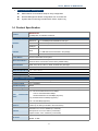
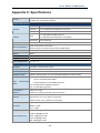
1.4 Product Specification
WNRT-617G
Product
150Mbps 802.11n Wireless 3G Router
Hardware Specification
Interface
WAN Port:
1 x 10/100Mbps Auto MDI/MDI-X RJ45 port
LAN Port:
4 x 10/100Mbps Auto MDI/MDI-X RJ45 ports
USB port
1 x USB 2.0 port
1 x Detachable RP-SMA Connector
Gain:
Antenna
1 x 5dBi SMA antenna included in the package
Orientation:
Power Button
WPS / Reset Button
Omni-directional
Power On/Off button at rear panel
WPS / Reset button at front panel
Push for above 5 seconds to reset to factory default setting
LED Indicators
PWR, SYS, WLAN, LAN x 4, WAN, 3G, WPS with green light
Material
Plastic
Dimension (W x D x H) 174 x 110 x 23 mm
Weight
200g
Power Requirement
12V DC, 1A
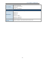
Wireless interface Specification
Standard
Compliance with IEEE 802.11b/g/n
Frequency Band
2.4~2.4835GHz
Extend Frequency
DSSS
Modulation Type
DBPSK, DQPSK, QPSK, CCK and OFDM (BPSK/QPSK/16-QAM/ 64-QAM)
11n: 135/121.5/108/81/54/40.5/27/13.5Mbps
Data
Transmission
Rates
130/117/104/78/52/39/26/13Mbps
65/58.5/52/39/26/19.5/13/6.5Mbps (Dynamic)
11g: 54/48/36/24/18/12/9/6Mbps (Dynamic)
11b: 11/5.5/2/1Mbps (Dynamic)
Transmission
Indoor up to 100m
Distance
outdoor up to 300m (it is limited to the environment)
America/ FCC: 2.414~2.462GHz (11 Channels)
Channel
Europe/ ETSI: 2.412~2.472GHz (13 Channels)
Japan/ TELEC: 2.412~2.484GHz (14 Channels)
RF Power
High: 18 dBm (max)
Middle: 15 dBm
-3-
User’s Manual of WNRT-617G
Low: 12 dBm
130M: -68dBm@10% PER
108M: -68dBm@10% PER
Receive Sensitivity
54M: -68dBm@10% PER
11M: -85dBm@8% PER
6M: -88dBm@10% PER
1M: -90dBm@8% PER
Wireless Management Features
Wireless
Operation
Mode
AP, WDS (AP+Bridge)
WEP (64/128/152-bit) encryption security
Encryption Security
WPA-PSK / WPA2-PSK (TKIP/AES)
WPA / WPA2 (TKIP/AES)
WPA / WPA2 enterprise mode (802.1x authentication)
Provide wireless LAN ACL (Access Control List) filtering
Wireless Security
Wireless MAC address filtering
Support WPS(WIFI Protected Setup )
Enable/Disable SSID Broadcast
Support 802.11e WMM (Wi-Fi Multimedia)
Wireless Advanced
Support Wireless Roaming
Provide Wireless Statistics
Router Features
Shares data and Internet access for users, supporting following internet access:
PPPoE / Russia PPPoE
Internet
Connection
Type
Dynamic IP
Static IP
Telstra Big Pond
PPTP / Russia PPTP
L2TP / Russia L2TP
NAT firewall with SPI (Stateful Packet Inspection)
NAT with ALG (Application Layer Gateway)
Firewall
Built-in NAT server supporting Virtual Server, and DMZ
Built-in firewall with IP address filtering, Domain Name filtering, and MAC address filtering
Support ICMP-FLOOD, UDP-FLOOD, TCP-SYN-FLOOD filter, DoS protection
Routing Protocol
Static Routing
VPN Pass-through
PPTP, L2TP, IPSec
Built-in DHCP server supporting static IP address distributing
Support UPnP, Dynamic DNS
Support Flow Statistics
LAN
IP & MAC Binding
IP / Protocol-based Bandwidth Control
Session Number: Max 5210
-4-
User’s Manual of WNRT-617G
Web-based (HTTP) management interface
Remote management
System Management
SNTP time synchronize
Easy firmware upgrade
System Log supports auto mail and save to local host
Windows 7(32-bit/64-bit)
OS Compatibility
Windows Vista (32-bit/64-bit)
Windows XP
Mac OS X 10.4 and higher
Standards Conformance
IEEE 802.11n (1T1R, up to 150Mbps)
IEEE 802.11g
IEEE 802.11b
IEEE Standards
IEEE 802.11i
IEEE 802.3 10Base-T
IEEE 802.3u 100Base-TX
IEEE 802.3x Flow Control
Others Protocols and
Standards
CSMA/CA, CSMA/CD, TCP/IP, DHCP, ICMP, NAT, PPPoE, SNTP
-5-
User’s Manual of WNRT-617G
Chapter 2. Hardware Installation
Please follow the instructions below to build the wireless network connection between WNRT-617G and your
computers.
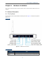
2.1 Hardware Description
2.1.1 The Front Panel
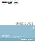
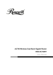
The front panel provides a simple interface monitoring the router. Figure 2-1 shows the front panel of
WNRT-617G.
Front Panel
Figure 2-1 WNRT-617G Front Panel
WPS/Reset Button
ACTIVE
TIME
WPS
Press and hold the button less than 5 seconds for WPS configuration
Reset
Press and hold the button more than 8 seconds to the factory default setting
-6-
User’s Manual of WNRT-617G
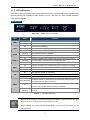
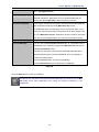
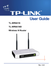
2.1.2 LED Indications
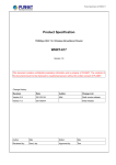
The LEDs on the front panel indicate instant status of port links, wireless data activity, system power;
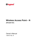
and help monitor and troubleshoot when needed. Figure 2-2 and Table 2-1 show the LED indications
of the Wireless Router.
LED Definition
Figure 2-2 WNRT-617G Front Panel
LED
Status
PWR
SYS
WLAN
LAN1-4
On
Power is on.
Off
Power is off.
On
The Router is initializing.
Flashing
The Router is working properly.
Off
The Router has a system error.
Flashing
The Wireless function is enabled.
Off
The Wireless function is disabled.
On
A device is linked to the corresponding port but there is no activity.
Flashing
WAN
No device is linked to the corresponding port.
On
A device is linked to the corresponding port but there is no activity.
An active device is linked to the corresponding port.
Off
No device is linked to the WAN port.
On
The USB 3G modem is connected.
Flashing
Off
Slow Flashing
WPS
An active device is linked to the corresponding port.
Off
Flashing
3G
Function
On
Quick
Flashing
Data is received or sent through the 3G modem.
No device is linked to the USB port.
A wireless device is connecting to the network by WPS function. This
process will last for about 2 minutes.
A wireless device has been successfully added to the network by WPS
function. The LED will keep on for about 5 minutes.
A wireless device has failed to be added to the network by WPS
function.
Table 2-1 The LEDs indication
1.
When a device has been successfully added to the network by WPS function, the WPS
LED will keep on for about 5 minutes and then turn off.
2.
When pressing and holding the WPS/Reset Button for more than 5 seconds, you will
reset the router.
-7-
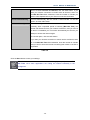
User’s Manual of WNRT-617G
The Rear Panel
Figure 2-3 Rear Panel
Interface
POWER
Function
The Power socket is where you will connect the power adapter.
Please use the power adapter provided with WNRT-617G.
ON/OFF
WAN
1,2,3,4 (LAN)
USB
The button of the power.
Connect to the DSL/cable Modem, or Ethernet
Connect to the user’s PC or network devices
Connect to the USB 3G modem
Table 2-2 The Interface indication
-8-
User’s Manual of WNRT-617G
Chapter 3. Connecting the Router
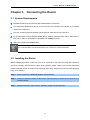
3.1 System Requirements
Broadband Internet Access Service (DSL/Cable/Ethernet connection)
One DSL/Cable Modem that has an RJ-45 connector (not necessary if the Router is connected
directly to the Ethernet.)
PCs with a working Ethernet Adapter and an Ethernet cable with RJ-45 connectors
PC of subscribers running Windows 98/ME, NT4.0, 2000/XP, Windows Vista / Win 7, MAC OS 9 or
later, Linux, UNIX or other platform compatible with TCP/IP protocols
Above PC installed with WEB Browser
It is recommended to use Internet Explore 7.0 or above to access the Router.
3.2 Installing the Router
Before installing the Router, make sure your PC is connected to the Internet through the broadband
service successfully at this moment. If there is any problem, please contact your local ISP. After that,
please install the Router according to the following steps. Don't forget to pull out the power plug and
keep your hands dry.
Step 1. Power off your PC, Cable/DSL Modem, and the Router.
Step 2. Locate an optimum location for the Router. The best place is usually at the center of your
wireless network.
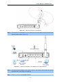
Step 3. Adjust the direction of the antenna. Normally, upright is a good direction.
-9-
User’s Manual of WNRT-617G
Figure 3-1 Adjust the direction of the antenna
Step 4. Connect the PC or Switch/Hub in your LAN to the LAN Ports (Yellow ports) of the Router with
Ethernet cable, shown in Figure 3-2.
Figure 3-2 Hardware Installation of the WNRT-617G Wireless Router
Step 5. Connect the power adapter to the power socket on the Router, and the other end into an
electrical outlet. Then power on the Router.
Step 6. Power on your PC and Cable/DSL Modem.
-10-
User’s Manual of WNRT-617G
Chapter 4. Quick Installation Guide
This chapter will show you how to configure the basic functions of your Wireless 3G Router using
Quick Setup within minutes.
A computer with wired Ethernet connection to the Wireless Router is required for the
first-time configuration.
4.1 Manual Network Setup - TCP/IP Configuration
The default IP address of the WNRT-617G is 192.168.1.1. And the default Subnet Mask is
255.255.255.0. These values can be changed as you desire. In this guide, we use all the default
values for description.
Connect the local PC to the LAN ports of the Router. And then you can configure the IP address for
your PC in the following two ways.
Obtain an IP address automatically
Configure the IP address manually
In the following sections, we’ll introduce how to install and configure the TCP/IP correctly in Windows
XP. First, make sure your Ethernet Adapter is working, and refer to the Ethernet adapter’s manual if
needed.
4.1.1 Obtain an IP Address Automatically
Summary:
1.
Set up the TCP/IP Protocol in "Obtain an IP address automatically" mode on your PC.
Then the WNRT-617G built-in DHCP server will assign IP address to the PC automatically.
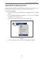
Install TCP/IP component
1)
On the Windows taskbar, click the Start button, point to Settings, and then click Control
Panel.
2)
Click the Network and Internet Connections icon, and then click on the Network
Connections tab in the appearing window.
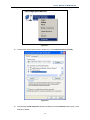
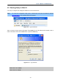
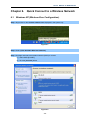
3)
Right click the icon shown below, select Properties on the prompt window.
-11-
User’s Manual of WNRT-617G
Figure 4-1
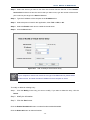
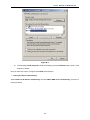
4)
In the prompt window shown below, double click on the Internet Protocol (TCP/IP).
Figure 4-2
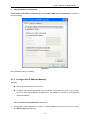
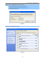
5)
The following TCP/IP Properties window will display and the IP Address tab is open on this
window by default.
-12-
User’s Manual of WNRT-617G
2.
Setting IP address automatically
Select Obtain an IP address automatically, Choose Obtain DNS server automatically, as shown in
the Figure below:
Figure 4-3
Now click OK to save your settings.
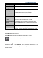
4.1.2 Configure the IP Address Manually
Summary:
Set up the TCP/IP Protocol for your PC.
Configure the network parameters. The IP address is 192.168.1.xxx ("xxx" is any number
from 2 to 254), Subnet Mask is 255.255.255.0, and Gateway is 192.168.1.1 (The Router's
default IP address)
1
Select Use the following IP address radio button.
2
If the Router's LAN IP address is 192.168.1.1, enter IP address 192.168.1.x (x is from 2 to 254),
and Subnet mask 255.255.255.0.
-13-
User’s Manual of WNRT-617G
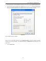
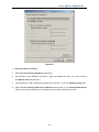
3
Enter the Router’s LAN IP address (the default IP is 192.168.1.1) into the Default gateway field.
4
Select Use the following DNS server addresses radio button. In the Preferred DNS Server
field, you can enter the DNS server IP address which has been provided by your ISP
Figure 4-4
Now click OK to save your settings.
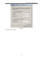
Now, you can run the Ping command in the command prompt to verify the network connection
between your PC and the Router. The following example is in Windows XP OS. Please follow the
steps below:
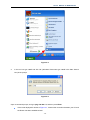
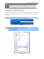
1.
Click on Start > Run.
-14-
User’s Manual of WNRT-617G
Figure 4-5
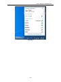
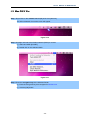
2.
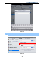
In the run box type “cmd” and click OK. (Windows Vista users type “cmd” in the Start .Search
box.)At the prompt.
Figure 4-6
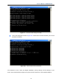
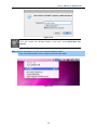
Open a command prompt, and type ping 192.168.1.1, and then press Enter.
If the result displayed is similar to Figure 4-7, it means the connection between your PC and
the Router has been established well.
-15-
User’s Manual of WNRT-617G
Figure 4-7 Success result of Ping command
If the result displayed is similar to Figure 4-8, it means the connection between your PC and
the Router has failed.
Figure 4-8 Failure result of Ping command
If the address is 0.0.0.0, check your adapter installation, security settings, and the settings on your
router. Some firewall software programs may block a DHCP request on newly installed adapters.
-16-
User’s Manual of WNRT-617G
1.
The 1/2/3/4 LEDs of LAN ports which you link to on the Router and LEDs on your PC's
adapter should be lit.
2.
If the Router's IP address is 192.168.1.1, your PC's IP address must be within the
range of 192.168.1.2 ~ 192.168.1.254.
-17-
User’s Manual of WNRT-617G
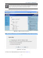
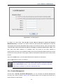
4.2 Starting Setup in Web UI
It is easy to configure and manage the WNRT-617G with web browser.
Step 1.
To access the configuration utility, open a web-browser and enter the default IP address
http://192.168.1.1 in the address field of the browser.
Figure 4-9 Login the Router
After a moment, a login window will appear. Enter admin for the User Name and Password, both in
lower case letters. Then click the OK button or press the Enter key.
Figure 4-10 Login Window
Default User name: admin
Default Password: admin
-18-
User’s Manual of WNRT-617G
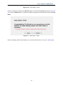
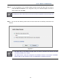
If the above screen does not pop up, it may mean that your web-browser has been set to a
proxy. Go to Tools menu>Internet Options>Connections>LAN Settings, in the screen that
appears, cancel the Using Proxy checkbox, and click OK to finish it.
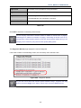
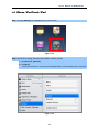
After entering the username and password, the main screen appears as Figure 4-11
Figure 4-11 WNRT-617G Web UI Screenshot
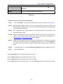
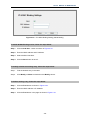
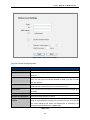
Step 2. After successfully login in, you can click the Quick Setup to quickly configure your Router.
Figure 4-12 Quick Setup
Click Next, and then Internet Access page will appear, shown in Figure 4-13.
-19-
User’s Manual of WNRT-617G
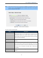
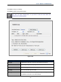
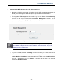
Step 3.
Select a desired Internet Access mode and then click Next. The configuration for each mode
is similar. Here we take 3G Preferred mode for example. Please refer to the procedures
below to configure the other modes.
Figure 4-13 Choose Internet Access Mode
The page includes the following fields:
Object
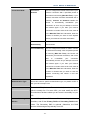
3G Preferred
Description
In this mode, the router will try 3G access first. If 3G access fails and
WAN access is valid, or if no 3G USB modem is inserted, the router
would switch to WAN access. Once the router succeeds to connect to
the 3G network, the router would stop the WAN connection and switch
back to 3G access immediately.
3G Only
In this mode, the router will try 3G access only. WAN access is
disabled.
WAN Preferred
In this mode, the router will try WAN access first. If the WAN access
fails, and 3G access is valid, the router would switch to 3G access.
Once the router succeeds to connect to the WAN network, the router
would stop the 3G connection and switch back to WAN access
immediately.
WAN Only
In this mode, the router will try WAN access only. 3G access is
disabled.
-20-
User’s Manual of WNRT-617G
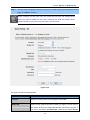
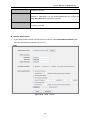
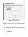
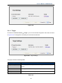
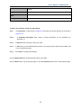
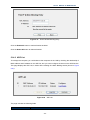
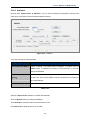
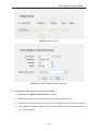
Step 4. The next screen will appear as shown in Figure 4-16. After finishing the configuration on this
page, click Next to continue,
Please configure the PIN code of the 3G modem first and save the settings before
insert your USB 3G Modem to the router. Otherwise, the USB 3G modem will be
locked possibly for trying the wrong PIN code over three times.
Figure 4-14
The page includes the following fields:
Object
Description
Location
Select the country where you're using the 3G modem.
Mobile ISP
Select the ISP (Internet Service Provider) you apply to for 3G service.
The router will show the default Dial Number and APN of that ISP. If
your ISP is not listed in the Mobile ISP, check the box before Set the
-21-
User’s Manual of WNRT-617G
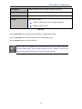
Dial Number and APN manually and manually fill the Dial Number
and APN blanks below.
Set the Dial Number
Check the box and fill the Dial Number and APN blanks below if your
and APN manually
ISP is not listed in the Mobile ISP list or the default values are not the
latest ones.
SIM/UIM PIN
Enter the PIN code if the SIM/UIM Protection is enabled. Please note
that 3 times of wrong PIN code will lock your SIM/UIM card. You need
to unlock it on the PC using PUK code.
Message
The PIN information of your SIM/UIM card.
Authentication Type
Some ISPs need a specific authentication type, so please confirm it
with your ISP or keep it Auto.
Dial Number & APN
Fill these two parameters manually after Set the Dial Number and
APN manually is checked.
Username & Password
Enter the Username and Password provided by your ISP. These fields
are optional but case-sensitive.
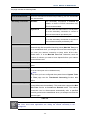
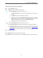
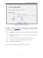
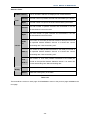
Step 5.
You will then see the Figure 4-15. Select Auto-Detect, the Router will automatically detect
the connection type your ISP provides. Make sure the cable is plugged into the WAN port
before detection. The appropriate configuration page will be displayed when an active
Internet service is successfully detected by the Router.
Figure 4-15
-22-
User’s Manual of WNRT-617G
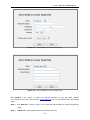
If the connection type detected is PPPoE, the next screen will appear as shown in Figure 4-16.
Enter the User Name and Password provided by your ISP. These fields are case-sensitive. If
you have difficulty with this process, please contact your ISP.
Figure 4-16 Quick Setup – PPPoE
If the connection type detected is Dynamic IP, the next screen will appear as shown in Figure
4-18. Then you can go on with the wireless configuration.
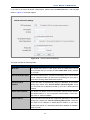
If the connection type detected is Static IP, the next screen will appear as shown in Figure 4-17.
Enter the parameters in the corresponding blanks.
Figure 4-17 Quick Setup - Static IP
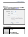
Step 6. Click Next to continue, the Wireless settings page will appear as shown in Figure 4-18.
-23-
User’s Manual of WNRT-617G
Figure 4-15 Quick Setup – Wireless
The page includes the following fields:
Object
Wireless Radio
Wireless
Description
Enable or disable the wireless radio choosing from the pull-down list.
Network Enter a value of up to 32 characters. The same Wireless Network Name
Name
(SSID: Service Set Identification) must be assigned to all wireless devices in
your network. Considering your wireless network security, the default SSID is
set to be default. This value is case-sensitive. For example, PLANET is NOT
the same as planet.
Region
Select your region from the pull-down list. This field specifies the region
where the wireless channel of the router can be used.
Channel
This field determines which operating frequency will be used. The default
channel is set to Auto, so the router will choose the best channel
automatically. It is not necessary to change the wireless channel unless you
notice interference problems with another nearby access point.
Mode
This field determines the wireless mode which the Router works on.
Channel Width
Select any channel width from the pull-down list. The default setting is
automatic, which can adjust the channel width for your clients automatically.
Max Tx Rate
You can limit the maximum transmission rate of the Router through this field.
-24-
User’s Manual of WNRT-617G
Wireless Security
Disable Security
The wireless security function can be enabled or
disabled. If disabled, the wireless stations will be
able to connect to the Router without encryption. It
is recommended strongly that you choose one of
following options to enable security.
WPA-PSK/WPA2-PSK
WPA-PSK/WPA2-PSK - Select WPA based on
pre-shared passphrase.
PSK Password - You can enter ASCII or
Hexadecimal characters.
For ASCII, the key can be made up of any
numbers 0 to 9 and any letters A to Z, the length
should be between 8 and 63 characters.
For Hexadecimal, the key can be made up of any
numbers 0 to 9 and letters A to F, the length
should be between 8 and 64 characters.
Please also note the key is case-sensitive.
No Change
If you choose this option, wireless security
configuration will not change.
These settings are only for basic wireless parameters. For advanced settings, please refer to Section
5.6: “Wireless”.
Step 7. Click the Next button. You will then see the Finish page.
If you don’t make any change on the Wireless page, you will see the Finish page as shown in Figure
4-19. Click the Finish button to finish the Quick Setup.
-25-
User’s Manual of WNRT-617G
Figure 4-16 Quick Setup – Finish
If there is something changed on the Wireless page, you will see the Finish page as shown in Figure
4-20. Click the Reboot button to make your wireless configuration to take effect and finish the Quick
Setup.
Figure 4-7 Quick Setup – Finish
After the rebooting, please check whether you can access the Internet or not in the 5.2 Status page.
-26-
User’s Manual of WNRT-617G
Chapter 5. Configuring the Router
This chapter will show each Web page's key functions and the configuration way.
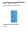
5.1 Login
After successfully login, you will see the fifteen main menus on the left of the Web-based utility. On the
right, there are the corresponding explanations and instructions.
Figure 5-1
The detailed explanations for each Web page’s key function are listed below.
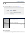
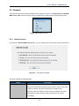
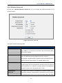
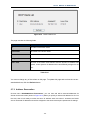
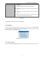
5.2 Status
The Status page provides the current status information about the Router. All information is read-only.
-27-
User’s Manual of WNRT-617G
Figure 5-2 Router Status
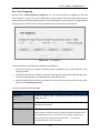
5.3 Quick Setup
Please refer to Section 4.2: Starting Setup in Web UI.
-28-
User’s Manual of WNRT-617G
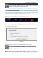
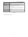
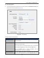
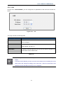
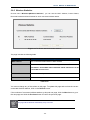
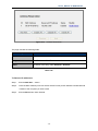
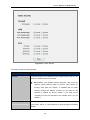
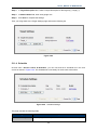
5.4 WPS
This section will guide you to add a new wireless device quickly to an existing network by WPS (Wi-Fi
Protected Setup) function.
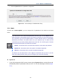
Step 1. Choose menu “WPS”, you will see the next screen (shown in Figure 5-3 ).
Figure 5-3 WPS
The page includes the following fields:
Object
Description
WPS Status
Enable or disable the WPS function here.
Current PIN
The current value of the Router's PIN displayed here. The default PIN
of the Router can be found in the label or User Guide.
Restore PIN
Restore the PIN of the Router to its default.
Gen New PIN
Click this button, and then you can get a new random value for the
Router's PIN. You can ensure the network security by generating a
new PIN.
Add device
You can add the new device to the existing network manually by
clicking this button.
Table 5-1
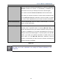
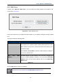
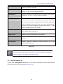
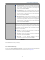
Step 2. To add a new device:
If the wireless adapter supports Wi-Fi Protected Setup (WPS), you can establish a wireless connection
between wireless adapter and Router using either Push Button Configuration (PBC) method or PIN
method.
-29-
User’s Manual of WNRT-617G
To build a successful connection by WPS, you should also do the corresponding
configuration of the new device for WPS function meanwhile.
I.
By Push Button Configuration (PBC)
If the wireless adapter supports Wi-Fi Protected Setup and the Push Button Configuration (PBC)
method, you can add it to the network by PBC with the following two methods.
Step 1: Press the WPS/Reset Button on the front panel of the Router.
Figure 5-4
Or you can keep the default WPS Status as Enabled and click the Add device button in Figure 5-3,
then the following screen will appear.
Figure 5-5
Choose Press the button of the new device in two minutes, and click Connect.
When pressing and holding the WPS/Reset Button on the router for more than 5
seconds, you will reset the router.
Step 2: Press and hold the WPS Button equipped on the adapter directly for 2 or 3 seconds. Or you
can click the WPS button with the same function in the configuration utility of the adapter.
-30-
User’s Manual of WNRT-617G
Step 3: Wait for a while until the next screen appears. Click Finish to complete the WPS
configuration.
II. By PIN
If the new device supports Wi-Fi Protected Setup and the PIN method, you can add it to the network by
PIN with the following two methods.
Method One: Enter the PIN of your Wireless adapter into the configuration utility of the Router
Step 1: Keep the default WPS Status as Enabled and click the Add device button in Figure 5-3,
then the following screen will appear.
Figure 5-6
Step 2: Choose Enter the new device's PIN and enter the PIN code of the wireless adapter in the
field behind PIN in the above figure. Then click Connect.
The PIN code of the adapter is always displayed on the WPS configuration screen.
Step 3: For the configuration of the wireless adapter, please choose the option that you want to
enter PIN into the Router in the configuration utility of the WPS, and click Next.
Method Two: Enter the PIN of the Router into the configuration utility of your Wireless adapter
Step 1: Get the Current PIN code of the Router in Figure 5-3 (each Router has its unique PIN code).
-31-
User’s Manual of WNRT-617G
Step 2: For the configuration of the wireless adapter, please choose the option that you want to
enter the PIN of the Router in the configuration utility of the Wireless adapter, and enter it
into the field. Then click Next.
The default PIN code of the Router can be found in WPS configuration screen as Figure 5-3.
Step 3. You will see the following screen when the new device has successfully connected to the
network.
Figure 5-7
1.
The WPS LED on the Router will light green for about 5 minutes if the device has been
successfully added to the network.
2.
The WPS function cannot be configured if the Wireless Function of the Router is disabled.
Please make sure the Wireless Function is enabled before configuring the WPS.
-32-
User’s Manual of WNRT-617G
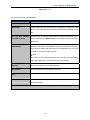
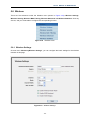
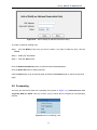
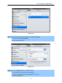
5.5 Network
There are five submenus under the Network menu (shown in Figure 5-8): Internet Access, 3G, WAN,
MAC Clone, LAN. Click any of them, and you will be able to configure the corresponding function.
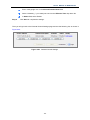
Figure 5-8 The Network menu
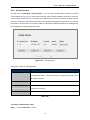
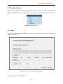
5.5.1 Internet Access
Choose menu “Network→Internet Access”, you can configure the access mode on the screen below.
Figure 5-9 Internet Access Mode
The page includes the following fields:
Object
3G Preferred
Description
In this mode, the router will try 3G access first;
When 3G access fails and WAN access is valid, or when no 3G USB
modem is inserted, the router would switch to WAN access;
When the router succeeds to connect to the 3G network, the router
would stop the WAN connection and switch back to 3G access
immediately.
-33-
User’s Manual of WNRT-617G
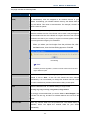
3G Only
In this mode, the router will try 3G access only. WAN access is
disabled.
WAN Preferred
In this mode, the router will try WAN access first;
When the WAN access fails, and 3G access is valid, the router would
switch to 3G access;
When the router succeeds to connect to the WAN network, the router
would stop the 3G connection and switch back to WAN access
immediately.
WAN Only
In this mode, the router will try WAN access only. 3G access is
disabled.
Table 5-2
Click the Save button to save your settings.
-34-
User’s Manual of WNRT-617G
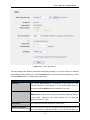
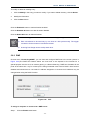
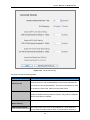
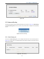
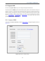
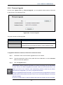
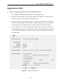
5.5.2 3G
Choose menu “Network→3G”, you can configure parameters for 3G function on the screen below.
Please do not insert the 3G USB Modem to the router before configure the settings. When the USB
modem is unplugged, corresponding information will be shown as in Figure 5-10.
1.
3G settings are unavailable when the Internet Access mode is set to WAN Only
mode. Please change settings on Internet Access if you want to use 3G.
2.
Please configure the PIN code of the 3G modem first and save the settings
before insert your USB 3G Modem to the router. Otherwise, the USB 3G modem
will be locked possibly for trying the wrong PIN code over three times.
There are already many kinds of 3G USB modem embedded in the router. The USB modem
parameters will be set automatically if it is supported by the Router. If your USB modem inserted is
supported by the Router, then its model name will be shown in the 3G USB Modem field. Otherwise,
“Unknown Modem” will be shown instead. Please visit our website to get the latest USB modems
compatibility list.
-35-
User’s Manual of WNRT-617G
Figure 5-10 3G
The page includes the following fields:
Object
Description
Location
Please select the location where you're enjoying the 3G Modem.
Mobile ISP
Please select the ISP (Internet Service Provider) you apply to for 3G
service. The router will show the default Dial Number and APN of that
ISP.
Set the Dial Number
Check the box and fill the Dial Number and APN blanks below if your
and APN manually
ISP is not listed in the Mobile ISP list or the default values are not the
latest ones.
SIM/UIM PIN
Enter the PIN code if the SIM/UIM Protection is enabled. Please note
that 3 times of wrong PIN code will lock your SIM/UIM card. You need
to unlock it on the PC using PUK code.
) Note:
No matter how many digits of the PIN code you input, there are always
eight digits displayed in this field after saving the settings.
Message
The PIN information of your SIM/UIM card.
Dial Number
Enter the Dial Number provided by your ISP.
APN
Enter the APN (Access Point Name) provided by your ISP.
Username/Password
Enter the Username and Password provided by your ISP. These fields
are case-sensitive.
Click the Connect button to connect to your 3G network.
-36-
User’s Manual of WNRT-617G
Connection Mode
Connect on
You can configure the Router to disconnect your
Demand
Internet connection after a specified period of
the Internet connectivity (Max Idle Time). If your
Internet connection has been terminated due to
inactivity, Connect on Demand enables the
Router
to
automatically
re-establish
your
connection as soon as you attempt to access
the Internet again. If you want your Internet
connection to remain active at all times, enter 0
in the Max Idle Time field. Otherwise, enter the
number of minutes you want to have elapsed
before your Internet connection terminates.
Connect
Connect automatically after the Router is
Automatically
disconnected.
Connect Manually
You can configure the Router to make it connect
or disconnect manually. After a specified period
of inactivity (Max Idle Time), the Router will
disconnect your Internet connection, and not be
able
to
re-establish
your
connection
automatically as soon as you attempt to access
the Internet again. If you want your Internet
connection to remain active at all times, enter 0
in the Max Idle Time field. Otherwise, enter the
number in minutes that you wish to have the
Internet connecting last unless a new link
requested.
Authentication Type
Some ISPs need a specific authentication type, so please confirm it
with your ISP or keep it Auto.
MTU Size
The default MTU (Maximum Transmission Unit) size is 1480 bytes,
which is usually fine. For some ISPs, you need modify the MTU.
This should not be done unless you are sure it is necessary for your
ISP.
Use the following DNS
If your ISP specifies a DNS server IP address for you, click the
Servers
checkbox, and fill the Primary DNS and Secondary DNS blanks
below. The Secondary DNS is optional. Otherwise, the DNS
servers will be assigned dynamically from ISP.
-37-
User’s Manual of WNRT-617G
Table 5-3
Click the Save button to save your settings.
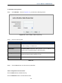
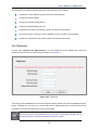
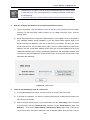
Click the Modem Settings button if your 3G USB Modem is not supported by the Router, and then you
will see the screen as shown in Figure 5-11. Parameters of your USB modem can be configured on
this page.
Sometimes the connection cannot be disconnected although you specify a time to
Max Idle Time because some applications visit the Internet continually in the
background.
Figure 5-11 3G USB Modem Settings
There are already many kinds of 3G USB modem embedded in the router. The USB modem
parameters will be set automatically if it is supported by the router. But when the router finds the 3G
USB modem "unknown", it will prompt you to set these parameters. The router can identify your
"unknown" 3G modem if the correct parameters are in the list. We suggest you do the “3G USB
Modem Setting” only in such circumstance.
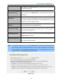
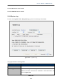
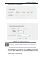
To add 3G USB Modem entries, follow the steps below.
1. Download the most recent 3G USB modem configuration file from our website.
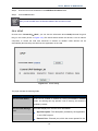
2. Click the Add New... button in Figure 5-11, and then you will see Figure 5-12.
3. Click Browse… to select the path name where you save the downloaded file on the computer
into the File blank.
-38-
User’s Manual of WNRT-617G
4. Click the Upload button to upload the configuration.
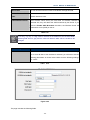
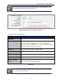
Figure 5-12 Add or Modify a 3G USB Modem Entry
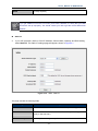
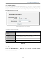
5.5.3 WAN
Choose menu “Network→WAN”, you can configure the IP parameters of the WAN on the screen
below.
If you don't know how to choose the appropriate connection type, click the Detect button to
allow the Router to automatically search your Internet connection for servers and protocols.
The connection type will be reported when an active Internet service is successfully
detected by the Router. This detect result is for your reference only. To make sure the
connection type your ISP provides, please refer to the ISP. The various types of Internet
connections that the Router can detect are as follows:
PPPoE - Connections which use PPPoE that requires a user name and password.
Dynamic IP - Connections which use dynamic IP address assignment.
Static IP - Connections which use static IP address assignment.
The Router can not detect PPTP / L2TP / BigPond connections with your ISP. If your ISP
uses one of these protocols, then you must configure your connection manually.
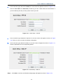
Dynamic IP
1.
If your ISP provides the DHCP service, please choose Dynamic IP type, and the Router will
automatically obtain IP parameters from your ISP. You can see the page as follows (Figure
5-13):
-39-
User’s Manual of WNRT-617G
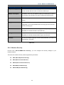
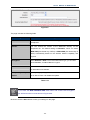
Figure 5-13 WAN - Dynamic IP
This page displays the WAN IP parameters assigned dynamically by your ISP, including IP address,
Subnet Mask, Default Gateway, etc. Click the Renew button to renew the IP parameters from your ISP.
Click the Release button to release the IP parameters.
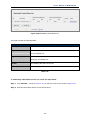
Object
MTU Size
Description
The normal MTU (Maximum Transmission Unit) value for most
Ethernet networks is 1500 Bytes. It is not recommended that you
change the default MTU Size unless required by your ISP.
Use These DNS Servers
If your ISP gives you one or two DNS addresses, select Use These
DNS Servers and enter the primary and secondary addresses into the
correct fields. Otherwise, the DNS servers will be assigned
dynamically from your ISP.
Host Name
This option specifies the Host Name of the Router.
Get IP with Unicast
A few ISPs' DHCP servers do not support the broadcast applications. If
you cannot get the IP Address normally, you can choose this option. (It
-40-
User’s Manual of WNRT-617G
DHCP
is rarely required.)
Table 5-4
If you get “Address not found” error when you access a Website, it is likely that your DNS
servers are set up improperly. You should contact your ISP to get the correct DNS server
address.
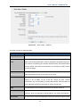
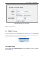
Static IP
2.
If your ISP provides a static or fixed IP Address, Subnet Mask, Gateway and DNS setting,
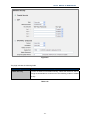
select Static IP. The Static IP settings page will appear, shown in Figure 5-1.
Figure 5-14 WAN - Static IP
The page includes the following fields:
Object
Description
IP Address
Enter the IP address in dotted-decimal notation provided by your ISP.
Subnet Mask
Enter the subnet Mask in dotted-decimal notation provided by your ISP,
usually is 255.255.255.0
Default Gateway
(Optional) Enter the gateway IP address in dotted-decimal notation
-41-
User’s Manual of WNRT-617G
provided by your ISP.
MTU Size
The normal MTU (Maximum Transmission Unit) value for most Ethernet
networks is 1500 Bytes. It is not recommended that you change the
default MTU Size unless required by your ISP.
Primary/Secondary DNS
(Optional) Enter one or two DNS addresses in dotted-decimal notation
provided by your ISP.
Table 5-5
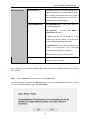
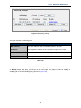
PPPoE / Rusia PPPoE
3.
If your ISP provides a PPPoE / Russia PPPoE connection, select PPPoE/Russia PPPoE option.
And enter the following parameters (Figure 5-1):
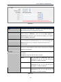
Figure 5-15 WAN – PPPoE
-42-
User’s Manual of WNRT-617G
The page includes the following fields:
Object
User Name/Password
Description
Enter the User Name and Password provided by your ISP. These fields
are case-sensitive.
Secondary Connection
Disabled
The Secondary Connection is disabled by
default, so there is PPPoE connection only.
This is recommended.
Dynamic IP
You can check this radio button to use Dynamic
IP as the secondary connection to connect to
the local area network provided by ISP.
Static IP
You can check this radio button to use Static
IP as the secondary connection to connect to
the local area network provided by ISP.
Connect on Demand
In this mode, the Internet connection can be terminated
automatically after a specified inactivity period (Max Idle Time) and
be re-established when you attempt to access the Internet again. If
you want your Internet connection to keep active all the time,
please enter “0” in the Max Idle Time field. Otherwise, enter the
number of minutes you want to have elapsed before your Internet
access disconnects.
Connect Automatically
The connection can be re-established automatically when it was
down.
Time-based Connecting
The connection will only be established in the period from the start time
to the end time (both are in HH:MM format).
) Note:
Only when you have configured the system time on System Tools
-> Time page can the Time-based Connecting function take
effect.
Connect Manually
You
can
click
the
Connect/
Disconnect
button
to
connect/disconnect immediately. This mode also supports the Max
Idle Time function as Connect on Demand mode. The Internet
connection can be disconnected automatically after a specified
inactivity period and re-established when you attempt to access the
Internet again.
Table 5-6
Sometimes the connection cannot be terminated although you specify a time to Max
Idle Time, since some applications are visiting the Internet continually in the
background.
-43-
User’s Manual of WNRT-617G
If you want to do some advanced configurations, please click the Advanced button, and the page
shown in Figure 5-16 will then appear:
Figure 5-16 PPPoE Advanced Settings
The page includes the following fields:
Object
MTU Size
Description
The default MTU size is “1480” bytes, which is usually fine. It is not
recommended that you change the default MTU Size unless required
by your ISP.
Service Name/AC Name
The service name and AC (Access Concentrator) name, which should
not be configured unless you are sure it is necessary for your ISP. In
most cases, leaving these fields blank will work.
ISP Specified IP
If your ISP does not automatically assign IP addresses to the Router
Address
during login, please click “Use IP address specified by ISP” check
box and enter the IP address provided by your ISP in dotted-decimal
notation.
Detect Online Interval
The Router will detect Access Concentrator online at every interval.
The default value is “0”. You can input the value between “0” and “120”.
The value “0” means no detect.
DNS IP address
If your ISP does not automatically assign DNS addresses to the Router
during login, please click “Use the following DNS servers” check box
and enter the IP address in dotted-decimal notation of your ISP’s
primary DNS server. If a secondary DNS server address is available,
enter it as well.
Table 5-7
-44-
User’s Manual of WNRT-617G
Click the Save button to save your settings.
BigPond Cable
4.
If your ISP provides BigPond Cable (or Heart Beat Signal) connection, please select BigPond
Cable. And you should enter the following parameters (Figure 5-17):
Figure 5-17
The page includes the following fields:
Object
User Name/Password
Description
Enter the User Name and Password provided by your ISP. These fields
are case-sensitive.
Auth Server
Enter the authenticating server IP address or host name.
Auth Domain
Type in the domain suffix server name based on your location.
e.g.
NSW / ACT - nsw.bigpond.net.au
VIC / TAS / WA / SA / NT - vic.bigpond.net.au
-45-
User’s Manual of WNRT-617G
QLD - qld.bigpond.net.au
MTU Size
The normal MTU (Maximum Transmission Unit) value for most
Ethernet networks is 1500 Bytes. It is not recommended that you
change the default MTU Size unless required by your ISP.
Connect on Demand
In this mode, the Internet connection can be terminated automatically
after a specified inactivity period (Max Idle Time) and be
re-established when you attempt to access the Internet again. If you
want your Internet connection to keep active all the time, please enter
“0” in the Max Idle Time field. Otherwise, enter the number of minutes
you want to have elapsed before your Internet access disconnects.
Connect Automatically
The connection can be re-established automatically when it was down.
Connect Manually
You can click the Connect/Disconnect button to connect/disconnect
immediately. This mode also supports the Max Idle Time function as
Connect on Demand mode.
The Internet connection can be disconnected automatically after a
specified inactivity period and re-established when you attempt to
access the Internet again.
Click the Connect button to connect immediately.
Click the Disconnect button to disconnect immediately.
Table 5-8
Click the Save button to save your settings.
Sometimes the connection cannot be terminated although you specify a time to Max
Idle Time, since some applications are visiting the Internet continually in the
background.
-46-
User’s Manual of WNRT-617G
L2TP / Russia L2TP
5.
If your ISP provides L2TP / Russia L2TP connection, please select L2TP/Russia L2TP option.
And enter the following parameters (Figure 5-18):
Figure 5-18 L2TP Settings
The page includes the following fields:
Object
User Name/Password
Description
Enter the User Name and Password provided by your ISP. These fields
are case-sensitive.
Dynamic IP/ Static IP
Choose either as you are given by your ISP. Click the Connect button
to connect immediately.
Click the Disconnect button to disconnect immediately.
Connect on Demand
You can configure the Router to disconnect from your Internet
connection after a specified period of inactivity (Max Idle Time). If your
Internet connection has been terminated due to inactivity, Connect on
Demand enables the Router to automatically re-establish your
connection as soon as you attempt to access the Internet again. If you
-47-
User’s Manual of WNRT-617G
wish to activate Connect on Demand, click the radio button. If you
want your Internet connection to remain active at all times, enter 0 in
the Max Idle Time field. Otherwise, enter the number of minutes you
want to have elapsed before your Internet connection terminates.
Connect Automatically
Connect automatically after the Router is disconnected. To use this
option, click the radio button.
Connect Manually
You can configure the Router to make it connect or disconnect
manually. After a specified period of inactivity (Max Idle Time), the
Router will disconnect from your Internet connection, and you will not
be able to re-establish your connection automatically as soon as you
attempt to access the Internet again.
To use this option, click the radio button.
If you want your Internet connection to remain active at all times, enter
"0" in the Max Idle Time field. Otherwise, enter the number in minutes
that you wish to have the Internet connecting last unless a new link is
requested.
Table 5-9
Click the Save button to save your settings.
Sometimes the connection cannot be terminated although you specify a time to Max
Idle Time, since some applications are visiting the Internet continually in the
background.
-48-
User’s Manual of WNRT-617G
PPTP / Russia PPTP
6.
If your ISP provides PPTP / Russia PPTP connection, please select PPTP/Russia PPTP option.
And enter the following parameters (Figure 5-19):
Figure 5-19 PPTP Settings
The page includes the following fields:
Object
User Name/Password
Description
Enter the User Name and Password provided by your ISP. These fields
are case-sensitive.
Dynamic IP/ Static IP
Choose either as you are given by your ISP and enter the ISP’s IP
address or the domain name.
If you choose static IP and enter the domain name, you should also
enter the DNS assigned by your ISP. And click the Save button.
Click the Connect button to connect immediately. Click the
Disconnect button to disconnect immediately.
Connect on Demand
You can configure the Router to disconnect from your Internet
connection after a specified period of inactivity (Max Idle Time). If your
-49-
User’s Manual of WNRT-617G
Internet connection has been terminated due to inactivity, Connect on
Demand enables the Router to automatically re-establish your
connection as soon as you attempt to access the Internet again.
If you wish to activate Connect on Demand, click the radio button.
If you want your Internet connection to remain active at all times, enter
0 in the Max Idle Time field. Otherwise, enter the number of minutes
you want to have elapsed before your Internet connection terminates.
Connect Automatically
Connect automatically after the Router is disconnected. To use this
option, click the radio button.
Connect Manually
You can configure the Router to make it connect or disconnect
manually. After a specified period of inactivity (Max Idle Time), the
Router will disconnect from your Internet connection, and you will not
be able to re-establish your connection automatically as soon as you
attempt to access the Internet again. To use this option, click the radio
button. If you want your Internet connection to remain active at all
times, enter "0" in the Max Idle Time field. Otherwise, enter the
number in minutes that you wish to have the Internet connecting last
unless a new link is requested.
Table 5-10
Sometimes the connection cannot be terminated although you specify a time to Max
Idle Time, since some applications are visiting the Internet continually in the
background.
-50-
User’s Manual of WNRT-617G
5.5.4 LAN
Choose menu “Network→LAN”, you can configure the IP parameters of the LAN on the screen as
below.
Figure 5-20 LAN
The page includes the following fields:
Object
MAC Address
Description
The physical address of the Router, as seen from the LAN. The value
can't be changed.
IP Address
Enter the IP address of your Router or reset it in dotted-decimal notation
(factory default: 192.168.1.1).
Subnet Mask
An address code that determines the size of the network. Normally use
255.255.255.0 as the subnet mask.
Table 5-11
1.
If you change the IP Address of LAN, you must use the new IP Address to login the
Router.
2.
If the new LAN IP Address you set is not in the same subnet, the IP Address pool of the
DHCP server will change accordingly at the same time,while the Virtual Server and
DMZ Host will not take effect until they are re-configured.
-51-
User’s Manual of WNRT-617G
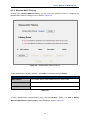
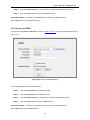
5.5.5 MAC Clone
Choose menu “Network→MAC Clone”, you can configure the MAC address of the WAN on the
screen below, Figure 5-21:
Figure 5-21 MAC Address Clone
Some ISPs require that you register the MAC Address of your adapter. Changes are rarely needed
here.
The page includes the following fields:
Object
Description
WAN MAC Address
This field displays the current MAC address of the WAN port. If your
ISP requires you to register the MAC address, please enter the correct
MAC address into this field in XX-XX-XX-XX-XX-XX format(X is any
hexadecimal digit).
Click Restore Factory MAC to restore the MAC address of WAN port
to the factory default value.
Your
PC's
Address
MAC
This field displays the MAC address of the PC that is managing the
Router. If the MAC address is required, you can click the Clone MAC
Address button and this MAC address will fill in the WAN MAC
Address field.
Table 5-12
Click the Save button to save your settings.
Only the PC on your LAN can use the MAC Address Clone function.
-52-
User’s Manual of WNRT-617G
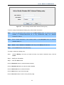
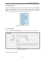
5.6 Wireless
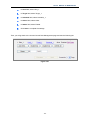
There are five submenus under the Wireless menu (shown in Figure 5-22): Wireless Settings,
Wireless Security, Wireless MAC Filtering, Wireless Advanced and Wireless Statistics. Click any
of them, and you will be able to configure the corresponding function.
Figure 5-22 Wireless menu
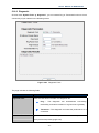
5.6.1 Wireless Settings
Choose menu “Wireless→Wireless Settings”, you can configure the basic settings for the wireless
network on this page.
Figure 5-23 Wireless Settings
-53-
User’s Manual of WNRT-617G
The page includes the following fields:
Object
Description
Wireless Network Name Enter a value of up to 32 characters. The same name of SSID (Service
(SSID)
Set Identification) must be assigned to all wireless devices in your
network. Considering your wireless network security, the default SSID is
set to be default. This value is case-sensitive. For example, PLANET is
NOT the same as planet.
Region
Select your region from the pull-down list. This field specifies the region
where the wireless function of the Router can be used. It may be illegal to
use the wireless function of the Router in a region other than one of those
specified in this field. If your country or region is not listed, please contact
your local government agency for assistance.
When you select your local region from the pull-down list, click
the Save button, then the Note Dialog appears. Click OK.
Note Dialog
) Note:
Limited by local law regulations, version for North America does not have
region selection option.
Channel
This field determines which operating frequency will be used. The default
channel is set to Auto, so the AP will choose the best channel
automatically. It is not necessary to change the wireless channel unless
you notice interference problems with another nearby access point.
Mode
Select the desired mode. The default setting is 11bgn mixed.
11b only, 11g only, 11n only, 11bg mixed, 11bgn mixed.
It is strongly recommended that you set the Mode to 802.11b&g&n, and
all of 802.11b, 802.11g, and 802.11n wireless stations can connect to the
Router.
Channel width
Select any channel width from the pull-down list. The default setting is
automatic, which can adjust the channel width for your clients
automatically.
-54-
User’s Manual of WNRT-617G
Max Tx Rate
You can limit the maximum tx rate of the Router through this field.
Enable Wireless Router The wireless radio of this Router can be enabled or disabled to allow
Radio
wireless stations access.
Enable SSID Broadcast
When wireless clients survey the local area for wireless networks to
associate with, they will detect the SSID broadcast by the Router. If you
select the Enable SSID Broadcast checkbox, the Wireless Router will
broadcast its name (SSID) on the air.
Table 5-13
If 11b only, 11g only, or 11bg mixed is selected in the Mode field, the Channel Width
selecting field will turn grey and the value will become 20M, which is unable to be
changed.
Object
Enable WDS
Description
Check this box to enable WDS. With this function, the Router can bridge
two or more WLANs. If this checkbox is selected, you will have to set the
following parameters as shown below. Make sure the following settings
are correct.
Table 5-14
Figure 5-24
The page includes the following fields:
-55-
User’s Manual of WNRT-617G
Object
SSID(to be bridged)
Description
The SSID of the AP your Router is going to connect to as a client. You
can also use the search function to select the SSID to join.
BSSID(to be bridged)
The BSSID of the AP your Router is going to connect to as a client.
You can also use the search function to select the BSSID to join.
Search
Click this button, you can search the AP which runs in the current
channel.
Key type
This option should be chosen according to the AP's security
configuration. It is recommended that the security type is the same as
your AP's security type.
WEP Index
This option should be chosen if the key type is WEP(ASCII) or
WEP(HEX).It indicates the index of the WEP key.
Auth Type
This option should be chosen if the key type is WEP(ASCII) or
WEP(HEX).It indicates the authorization type of the Root AP.
Password
If the AP your Router is going to connect needs password, you need to fill
the password in this blank.
Table 5-15
5.6.2 Wireless Security
Choose menu “Wireless→Wireless Security”, you can configure the security settings of your
wireless network.
There are five wireless security modes supported by the Router:
WEP (Wired Equivalent Privacy)
WPA (Wi-Fi Protected Access)
WPA2 (Wi-Fi Protected Access 2)
WPA-PSK (Pre-Shared Key)
WPA2-PSK (Pre-Shared Key)
-56-
User’s Manual of WNRT-617G
Figure 5-2
The page includes the following fields:
Object
Disable Security
Description
If you do not want to use wireless security, select this check box, but it’s
strongly recommended to choose one of the following modes to enable
security.
Table 5-16
-57-
User’s Manual of WNRT-617G
Figure 5-3
Object
WEP
Description
It is based on the IEEE 802.11 standard. If you select this check box,
you will find a notice in red as show in Figure 5-3.
Type
you can choose the type for the WEP security on the pull-down list. The
default setting is Automatic, which can select Open System or
Shared Key authentication type automatically based on the wireless
station's capability and request.
WEP Key Format
Hexadecimal and ASCII formats are provided. Hexadecimal format stands
for any combination of hexadecimal digits (0-9, a-f, A-F) in the specified length.
ASCII format stands for any combination of keyboard characters in the
specified length.
WEP Key
Select which of the four keys will be used and enter the matching WEP
key that you create. Make sure these values are identical on all wireless
stations in your network.
Key Type
You can select the WEP key length (64-bit, or 128-bit, or 152-bit.) for
encryption.
"Disabled" means this WEP key entry is invalid.
64-bit
You can enter 10 hexadecimal digits (any
combination of 0-9, a-f, A-F, zero key is not
promoted) or 5 ASCII characters.
128-bit
You can enter 26 hexadecimal digits (any
combination of 0-9, a-f, A-F, zero key is not
promoted) or 13 ASCII characters.
152-bit
You can enter 32 hexadecimal digits (any
combination of 0-9, a-f, A-F, zero key is not
promoted) or 16 ASCII characters.
Table 5-17
-58-
User’s Manual of WNRT-617G
If you do not set the key, the wireless security function is still disabled even if you
have selected Shared Key as Authentication Type.
Figure 5-4 WPA/WPA2 Configuration Screenshot
The page includes the following fields:
Object
Description
WPA/WPA2
It is based on Radius Server.
Version
you can choose the version of the WPA security on the pull-down list.
The default setting is Automatic, which can select WPA (Wi-Fi
Protected Access) or WPA2 (WPA version 2) automatically based on
the wireless station's capability and request.
Encryption
You can select either Automatic, or TKIP or AES.
Radius Server IP
Enter the IP address of the Radius Server.
Radius Port
Enter the port that radius service used.
Radius Password
Enter the password for the Radius Server.
Group Key Update
Specify the group key update interval in seconds. The value should be
Period
30 or above. Enter 0 to disable the update.
Table 5-18
If you check the WPA/WPA2 radio button and choose TKIP encryption, you will find a
notice in red as shown in Figure 5-4.
-59-
User’s Manual of WNRT-617G
Figure 5-5
The page includes the following fields:
Object
Description
WPA-PSK/WPA2-PSK
It’s the WPA/WPA2 authentication type based on pre-shared
passphrase.
Version
you can choose the version of the WPA-PSK security on the
drop-down list. The default setting is Automatic, which can select
WPA-PSK (Pre-shared key of WPA) or WPA2-PSK (Pre-shared key of
WPA) automatically based on the wireless station's capability and
request.
Encryption
When WPA-PSK or WPA is set as the Authentication Type, you can select
either Automatic, or TKIP or AES as Encryption.
PSK Password
You can enter ASCII characters between 8 and 63 characters or 8 to
64 Hexadecimal characters.
Group
Period
Key
Update
Specify the group key update interval in seconds. The value should be
30 or above. Enter 0 to disable the update.
Table 5-19
If you check the WPA-PSK/WPA2-PSK radio button and choose TKIP encryption,
you will find a notice in red as shown in Figure 5-28.
Be sure to click the Save button to save your settings on this page.
-60-
User’s Manual of WNRT-617G
5.6.3 Wireless MAC Filtering
Choose menu “Wireless→MAC Filtering”, you can control the wireless access by configuring the
Wireless MAC Address Filtering function, shown in Figure 5-6.
Figure 5-6 Wireless MAC address Filtering
To filter wireless users by MAC Address, click Enable. The default setting is Disable.
Object
Description
MAC Address
The wireless station's MAC address that you want to filter.
Status
The status of this entry either Enabled or Disabled.
Description
A simple description of the wireless station.
Table 5-20
To Add a Wireless MAC Address filtering entry, click the Add New… button. The "Add or Modify
Wireless MAC Address Filtering entry" page will appear, shown in Figure 5-7:
-61-
User’s Manual of WNRT-617G
Figure 5-7 Add or Modify Wireless MAC Address Filtering entry
To add or modify a MAC Address Filtering entry, follow these instructions:
Step 1.
Enter the appropriate MAC Address into the MAC Address field. The format of the MAC
Address
is
XX-XX-XX-XX-XX-XX
(X
is
any
hexadecimal
digit).
For
example:
00-30-4F-11-22-33.
Step 2. Enter a simple description of the wireless station in the Description field. For example:
Wireless station A.
Step 3. Status - Select Enabled or Disabled for this entry on the Status pull-down list.
Step 4. Click the Save button to save this entry.
To modify or delete an existing entry:
Step 1.
Click the Modify in the entry you want to modify. If you want to delete the entry, click the
Delete.
Step 2. Modify the information.
Step 3. Click the Save button.
Click the Enable All button to make all entries enabled
Click the Disabled All button to make all entries disabled.
Click the Delete All button to delete all entries
Click the Next button to go to the next page
Click the Previous button to return to the previous page.
-62-
User’s Manual of WNRT-617G
For example: If you desire that the wireless station A with MAC address 00-30-4F-11-22-33 and the
wireless station B with MAC address 00-30-4F-1A-2B-3C are able to access the Router, but all the
other wireless stations cannot access the Router, you can configure the Wireless MAC Address
Filtering list by following these steps:
Step 1. Click the Enable button to enable this function.
Step 2. Select the radio button: Deny the stations not specified by any enabled entries in the list
to access for Filtering Rules.
Step 3. Delete all or disable all entries if there are any entries already.
Step 4. Click
the
Add
New...
button
and
enter
the
MAC
address
00-30-4F-11-22-33
/00-30-4F-1A-2B-3C in the MAC Address field, then enter wireless station A/B in the
Description field, while select Enabled in the Status pull-down list. Finally, click the Save and
the Back button.
The filtering rules that configured should be similar to the following list:
Figure 5-31
-63-
User’s Manual of WNRT-617G
5.6.4 Wireless Advanced
Choose menu “Wireless→Wireless Advanced”, you can configure the advanced settings of your
wireless network.
Figure 5-8 Wireless Advanced
The page includes the following fields:
Object
Transmit Power
Description
Here you can specify the transmit power of Router. You can select
High, Middle or Low which you would like. High is the default setting
and is recommended.
Beacon Interval
Enter a value between 20-1000 milliseconds for Beacon Interval
here. The beacons are the packets sent by the router to
synchronize a wireless network. Beacon Interval value determines
the time interval of the beacons. The default value is 100.
RTS Threshold
Here you can specify the RTS (Request to Send) Threshold. If the
packet is larger than the specified RTS Threshold size, the router will
send RTS frames to a particular receiving station and negotiate the
sending of a data frame. The default value is 2346.
Fragmentation
This value is the maximum size determining whether packets will be
Threshold
fragmented. Setting the Fragmentation Threshold too low may result in
poor network performance since excessive packets. 2346 is the default
-64-
User’s Manual of WNRT-617G
setting and is recommended.
DTIM Interval
This value determines the interval of the Delivery Traffic Indication
Message (DTIM). A DTIM field is a countdown field informing clients of
the next window for listening to broadcast and multicast messages.
When the Router has buffered broadcast or multicast messages for
associated clients, it sends the next DTIM with a DTIM Interval value.
You can specify the value between 1-255 Beacon Intervals. The
default value is 1, which indicates the DTIM Interval is the same as
Beacon Interval.
Enable WMM
WMM function can guarantee the packets with high- priority messages
being transmitted preferentially. It is strongly recommended enabled.
Enable Short GI
This function is recommended for it will increase the data capacity by
reducing the guard interval time.
Enabled AP Isolation
This function can isolate wireless stations on your network from each
other. Wireless devices will be able to communicate with the Router
but not with each other. To use this function, check this box. AP
Isolation is disabled by default.
Table 5-21
If you are not familiar with the setting items in this page, it's strongly recommended to keep the
provided default values; otherwise it may result in lower wireless network performance.
-65-
User’s Manual of WNRT-617G
5.6.5 Wireless Statistics
Choose menu “Wireless→Wireless Statistics”, you can see the MAC Address, Current Status,
Received Packets and Sent Packets for each connected wireless station.
Figure 5-9 The Router attached wireless stations
The page includes the following fields:
Object
Description
MAC Address
The connected wireless station's MAC address
Current Status
The connected wireless station's running status, one of STA-AUTH /
STA-ASSOC / STA-JOINED / WPA / WPA-PSK / WPA2 / WPA2-PSK / AP-UP
/ AP-DOWN / Disconnected
Received Packets
Packets received by the station
Sent Packets
Packets sent by the station
Table 5-22
You cannot change any of the values on this page. To update this page and to show the current
connected wireless stations, click on the Refresh button.
If the numbers of connected wireless stations go beyond one page, click the Next button to go to
the next page and click the Previous button to return the previous page.
This page will be refreshed automatically every 5 seconds.
-66-
User’s Manual of WNRT-617G
5.7 DHCP
There are three submenus under the DHCP menu (shown in Figure 5-10): DHCP Settings, DHCP
Clients List and Address Reservation. Click any of them, and you will be able to configure the
corresponding function.
Figure 5-10 The DHCP menu
5.7.1 DHCP Settings
Choose menu “DHCP→DHCP Settings”, you can configure the DHCP Server on the page (shown in
Figure 5-11).The Router is set up by default as a DHCP (Dynamic Host Configuration Protocol) server,
which provides the TCP/IP configuration for all the PC(s) that are connected to the Router on the LAN.
Figure 5-11 DHCP Settings
The page includes the following fields:
Object
DHCP Server
Description
Enable or Disable the DHCP server. If you disable the Server, you must
have another DHCP server within your network or else you must
-67-
User’s Manual of WNRT-617G
configure the computer manually.
Start IP Address
Specify an IP address for the DHCP Server to start with when assigning IP
addresses. 192.168.1.100 is the default start address.
End IP Address
Specify an IP address for the DHCP Server to end with when assigning
IP addresses. 192.168.1.199 is the default end address.
Address Lease Time
The Address Lease Time is the amount of time a network user will be
allowed connection to the Router with their current dynamic IP Address.
Enter the amount of time in minutes and the user will be "leased" this
dynamic IP Address. After the time is up, the user will be automatically
assigned a new dynamic IP address. The range of the time is 1 ~ 2880
minutes. The default value is 120 minutes.
Default Gateway
(Optional.) Suggest to input the IP address of the LAN port of the
Router, default value is 192.168.1.1
Default Domain
(Optional.) Input the domain name of your network.
Primary DNS
(Optional.) Input the DNS IP address provided by your ISP. Or consult
your ISP.
Secondary DNS
(Optional.) Input the IP address of another DNS server if your ISP
provides two DNS servers.
Table 5-23
To use the DHCP server function of the Router, you must configure all computers on
the LAN as "Obtain an IP Address automatically" mode.
5.7.2 DHCP Clients List
Choose menu “DHCP→DHCP Clients List”, you can view the information about the clients attached
to the Router in the next screen (shown in Figure 5-12).
-68-
User’s Manual of WNRT-617G
Figure 5-12 DHCP Clients List
The page includes the following fields:
Object
Description
ID
The index of the DHCP Client
Client Name
The name of the DHCP client
MAC Address
The MAC address of the DHCP client
Assigned IP
The IP address that the Router has allocated to the DHCP client.
Lease Time
The time of the DHCP client leased. After the dynamic IP address has
expired, a new dynamic IP address will be automatically assigned to the
user.
Table 5-24
You cannot change any of the values on this page. To update this page and to show the current
attached devices, click the Refresh button.
5.7.3 Address Reservation
Choose menu “DHCP→Address Reservation”, you can view and add a reserved addresses for
clients via the next screen (shown in Figure 5-13).When you specify a reserved IP address for a PC on
the LAN, that PC will always receive the same IP address each time when it accesses the DHCP
server. Reserved IP addresses should be assigned to the servers that require permanent IP settings.
-69-
User’s Manual of WNRT-617G
Figure 5-13 Address Reservation
The page includes the following fields:
Object
Description
MAC Address
The MAC address of the PC for which you want to reserve IP address.
Assigned IP Address
The IP address of the Router reserved.
Status
The status of this entry either Enabled or Disabled.
Table 5-25
To Reserve IP addresses:
Step 1.
Step 2.
Click the Add New … button.
Enter the MAC address (in XX-XX-XX-XX-XX-XX format.) and IP address in dotted-decimal
notation of the computer you wish to add.
Step 3.
Click the Save button when finished.
-70-
User’s Manual of WNRT-617G
Figure 5-14 Add or Modify an Address Reservation Entry
To modify or delete an existing entry:
Step 1.
Click the Modify in the entry you want to modify. If you want to delete the entry, click the
Delete.
Step 2. Modify the information.
Step 3. Click the Save button.
Click the Enable/ Disabled All button to make all entries enabled/disabled
Click the Delete All button to delete all entries
Click the Next button to go to the next page and Click the Previous button to return the previous
page.
5.8 Forwarding
There are four submenus under the Forwarding menu (shown in Figure 5-15): Virtual Servers, Port
Triggering, DMZ and UPnP. Click any of them, and you will be able to configure the corresponding
function.
Figure 5-15 The Forwarding menu
-71-
User’s Manual of WNRT-617G
5.8.1 Virtual Servers
Choose menu “Forwarding→Virtual Servers”, you can view and add virtual servers in the next
screen (shown in Figure 5-16). Virtual servers can be used for setting up public services on your LAN,
such as DNS, Email and FTP. A virtual server is defined as a service port, and all requests from the
Internet to this service port will be redirected to the computer specified by the server IP. Any PC that
was used for a virtual server must have a static or reserved IP Address because its IP Address may
be changed when using the DHCP function.
Figure 5-16 Virtual Servers
The page includes the following fields:
Object
Service Port
Description
The numbers of External Ports. You can type a service port or a range of
service ports (in XXX – YYY format, XXX is the start port number, YYY is
the end port number).
IP Address
The IP Address of the PC providing the service application.
Protocol
The protocol used for this application, either TCP, UDP, or All (all protocols
supported by the Router).
Status
The status of this entry either Enabled or Disabled.
Table 5-26
To setup a virtual server entry:
Step 1. Click the Add New… button.
-72-
User’s Manual of WNRT-617G
Step 2. Select the service you want to use from the Common Service Port list. If the Common
Service Port list does not have the service that you want to use, type the number of the service
port or service port range in the Service Port box.
Step 3. Type the IP Address of the computer in the IP Address box.
Step 4. Select the protocol used for this application, either TCP or UDP, or All.
Step 5. Select the Enable check box to enable the virtual server.
Step 6. Click the Save button.
Figure 5-17 Add or Modify a Virtual Server Entry
If your computer or server has more than one type of available service, please select
another service, and enter the same IP Address for that computer or server.
To modify or delete an existing entry:
Step 1.
Click the Modify in the entry you want to modify. If you want to delete the entry, click the
Delete.
Step 2. Modify the information.
Step 3. Click the Save button.
Click the Enable/ Disabled All button to make all entries enabled/ disabled.
Click the Delete All button to delete all entries.
-73-
User’s Manual of WNRT-617G
Click the Next button to go to the next page and click the Previous button to return the previous
page.
If you set the service port of the virtual server as 80, you must set the Web
management port on System Tools –> Remote Management page to be any other
value except 80 such as 8080. Otherwise there will be a conflict to disable the virtual
server.
-74-
User’s Manual of WNRT-617G
5.8.2 Port Triggering
Choose menu “Forwarding→Port Triggering”, you can view and add port triggering in the next
screen (shown in Figure 5-18). Some applications require multiple connections, like Internet games,
video conferencing, Internet calling and so on. These applications cannot work with a pure NAT Router.
Port Triggering is used for some of these applications that can work with an NAT Router.
Figure 5-18 Port Triggering
Once the Router is configured, the operation is as follows:
1. A local host makes an outgoing connection using a destination port number defined in the
Trigger Port field.
2. The Router records this connection, opens the incoming port or ports associated with this entry
in the Port Triggering table, and associates them with the local host.
3. When necessary the external host will be able to connect to the local host using one of the ports
defined in the Incoming Ports field.
The page includes the following fields:
Object
Trigger Port
Description
The port for outgoing traffic. An outgoing connection using this port will
"Trigger" this rule.
Trigger Protocol
The protocol used for Trigger Ports, either TCP, UDP, or All (all protocols
supported by the Router).
Incoming Ports Range
The port or port range used by the remote system when it responds to the
outgoing request. A response using one of these ports will be forwarded to the
PC that triggered this rule. You can input at most 5 groups of ports (or port
section). Every group of ports must be set apart with ",". For example,
2000-2038, 2050-2051, 2085, 3010-3030.
-75-
User’s Manual of WNRT-617G
The protocol used for Incoming Ports Range, either TCP or UDP, or ALL
Incoming Protocol
(all protocols supported by the Router).
The status of this entry either Enabled or Disabled.
Status
Table 5-27
To add a new rule, follow the steps below.
Step 1.
Click the Add New… button, the next screen will pop up as shown in Figure 5-19.
Step 2.
Select a common application from the Common Applications drop-down list, then the
Trigger Port field and the Incoming Ports field will be automatically filled. If the Common
Applications do not have the application you need, enter the Trigger Port and the
Incoming Ports manually.
Step 3.
Select the protocol used for Trigger Port from the Trigger Protocol drop-down list, either
TCP, UDP, or All.
Step 4.
Select the protocol used for Incoming Ports from the Incoming Protocol drop-down list,
either TCP or UDP, or All.
Step 5.
Select Enable in Status field.
Step 6.
Click the Save button to save the new rule.
Figure 5-19 Add or Modify a Triggering Entry
-76-
User’s Manual of WNRT-617G
To modify or delete an existing entry:
1.
Click the Modify in the entry you want to modify. If you want to delete the entry, click the Delete.
2.
Modify the information.
3.
Click the Save button.
Click the Enable All button to make all entries enabled
Click the Disabled All button to make all entries disabled.
Click the Delete All button to delete all entries
1)
When the trigger connection is released, the according opening ports will be closed.
2)
Each rule allowed to be used only by one host on LAN synchronously. The trigger
connection of other hosts on LAN will be refused.
3)
Incoming Port Range cannot overlap each other.
5.8.3 DMZ
Choose menu “Forwarding→DMZ”, you can view and configure DMZ host in the screen (shown in
Figure 5-20).The DMZ host feature allows one local host to be exposed to the Internet for a
special-purpose service such as Internet gaming or videoconferencing. DMZ host forwards all the
ports at the same time. Any PC whose port is being forwarded must have its DHCP client function
disabled and should have a new static IP Address assigned to it because its IP Address may be
changed when using the DHCP function.
Figure 5-20 DMZ
To assign a computer or server to be a DMZ server:
Step 1.
Click the Enable radio button
-77-
User’s Manual of WNRT-617G
Step 2.
Enter the local host IP Address in the DMZ Host IP Address field
Step 3.
Click the Save button.
After you set the DMZ host, the firewall related to the host will not work.
5.8.4 UPnP
Choose menu “Forwarding→UPnP”, you can view the information about UPnP(Universal Plug and
Play) in the screen (shown in Figure 5-21).The UPnP feature allows the devices, such as Internet
computers, to access the local host resources or devices as needed. UPnP devices can be
automatically discovered by the UPnP service application on the LAN.
Figure 5-21 UPnP Setting
The page includes the following fields:
Object
Current UPnP Status
Description
UPnP can be enabled or disabled by clicking the Enable or Disable
button. As allowing this may present a risk to security, this feature is
enabled by default.
Current UPnP Settings
List
This table displays the current UPnP information.
App Description -The description provided by the application
in the UPnP request
External Port - External port, which the router opened for the
-78-
User’s Manual of WNRT-617G
application.
Protocol - Shows which type of protocol is opened.
Internal Port - Internal port, which the router opened for local
host.
IP Address - The UPnP device that is currently accessing the
router.
Status - The port’s status displayed here. “Enabled” means that
port is still active. Otherwise, the port is inactive.
Table 5-28
Click Refresh to update the Current UPnP Settings List.
5.9 Security
There are four submenus under the Security menu as shown in Figure 5-22: Basic Security,
Advanced Security, Local Management and Remote Management. Click any of them, and you will
be able to configure the corresponding function.
Figure 5-22 The Security menu
5.9.1 Basic Security
Choose menu “Security → Basic Security”, you can configure the basic security in the next screen.
-79-
User’s Manual of WNRT-617G
Figure 5-23 Basic Security
The page includes the following fields:
Object
Firewall
Description
A firewall protects your network from the outside world. Here you can
enable or disable the Router’s firewall.
SPI Firewall - SPI (Stateful Packet Inspection, also known as
dynamic packet filtering) helps to prevent cyber attacks by
tracking more state per session. It validates that the traffic
passing through the session conforms to the protocol. SPI
Firewall is enabled by factory default. If you want all the
computers on the LAN exposed to the outside world, you can
disable it.
VPN
VPN Passthrough must be enabled if you want to allow VPN tunnels
using IPSec, PPTP, or L2TP protocols to pass through the Router’s
firewall.
-80-
User’s Manual of WNRT-617G
PPTP Passthrough - Point-to-Point Tunneling Protocol (PPTP)
allows the Point-to-Point Protocol (PPP) to be tunneled through
an IP network. To allow PPTP tunnels to pass through the
Router, keep the default, Enabled.
L2TP Passthrough - Layer 2 Tunneling Protocol (L2TP) is the
method used to enable Point-to-Point sessions via the Internet on
the Layer 2 level. To allow L2TP tunnels to pass through the
Router, keep the default, Enabled.
IPSec Passthrough - Internet Protocol Security (IPSec) is a suite
of protocols for ensuring private, secure communications over
Internet Protocol (IP) networks, through the use of cryptographic
security services. To allow IPSec tunnels to pass through the
Router, keep the default, Enabled.
ALG
It is recommended to enable Application Layer Gateway (ALG)
because ALG allows customized Network Address Translation (NAT)
traversal filters to be plugged into the gateway to support address and
port translation for certain application layer "control/data" protocols
such as FTP, TFTP, H323 etc.
FTP ALG - To allow FTP clients and servers to transfer data
across NAT, keep the default Enable.
TFTP ALG - To allow TFTP clients and servers to transfer data
across NAT, keep the default Enable.
H323
ALG
-
To
allow
Microsoft
NetMeeting
clients
to
communicate across NAT, keep the default Enable.
Table 5-29
Click the Save button to save your settings.
5.9.2 Advanced Security
Choose menu “Security → Advanced Security”, you can protect the Router from being attacked by
TCP-SYN Flood, UDP Flood and ICMP-Flood in the screen as shown in Figure 5-24.
-81-
User’s Manual of WNRT-617G
Figure 5-24 Advanced Security
The page includes the following fields:
Object
Description
Packets Statistics
The default value is 10. Select a value between 5 and 60 seconds from
Interval (5~60)
the drop-down list. The Packets Statistics Interval value indicates the
time section of the packets statistics. The result of the statistics is used
for analysis by SYN Flood, UDP Flood and ICMP-Flood.
DoS Protection
Denial of Service protection. Check the Enable or Disable button to
enable or disable the DoS protection function. Only when it is enabled,
will the flood filters be enabled.
Enable ICMP-FLOOD
Enable or Disable the ICMP-FLOOD Attack Filtering.
Attack Filtering
ICMP-FLOOD Packets
The default value is 50. Enter a value between 5 ~ 3600. When the
current ICMP-FLOOD Packets number is beyond the set value, the
-82-
User’s Manual of WNRT-617G
Threshold (5~3600)
Router will startup the blocking function immediately.
Enable UDP-FLOOD
Enable or Disable the UDP-FLOOD Filtering.
Filtering
UDP-FLOOD Packets
The default value is 500. Enter a value between 5 ~ 3600. When the
Threshold (5~3600)
current UPD-FLOOD Packets number is beyond the set value, the
Router will startup the blocking function immediately.
Enable TCP-SYN-FLOOD Enable or Disable the TCP-SYN-FLOOD Attack Filtering.
Attack Filtering
TCP-SYN-FLOOD
The default value is 50. Enter a value between 5 ~ 3600. When the
Packets Threshold
current TCP-SYN-FLOOD Packets numbers is beyond the set value,
(5~3600)
the Router will startup the blocking function immediately.
Ignore Ping Packet From Enable or Disable Ignore Ping Packet From WAN Port. The default
WAN Port
setting is disabled. If enabled, the ping packet from the Internet cannot
access the Router.
Forbid Ping Packet From Enable or Disable Forbid Ping Packet From LAN Port. The default
LAN Port
setting is disabled. If enabled, the ping packet from LAN cannot access
the Router. This function can be used to defend against some viruses.
Table 5-30
Click the Save button to save the settings.
Click the Blocked DoS Host List button to display the DoS host table by blocking.
DoS Protection will take effect only when the Traffic Statistics in “System Tool →
Traffic Statistics” is enabled.
5.9.3 Local Management
Choose menu “Security → Local Management”, you can configure the management rule in the
screen as shown in Figure 5-25. The management feature allows you to deny computers in LAN from
accessing the Router.
-83-
User’s Manual of WNRT-617G
Figure 5-25 Local Management
By default, the radio button “All the PCs on the LAN are allowed to access the Router's
Web-Based Utility” is checked. If you want to allow PCs with specific MAC Addresses to access the
Setup page of the Router's Web-Based Utility locally from inside the network, check the radio button
“Only the PCs listed can browse the built-in web pages to perform Administrator tasks”, and
then enter each MAC Address in a separate field. The format for the MAC Address is
XX-XX-XX-XX-XX-XX (X is any hexadecimal digit). Only the PCs with MAC address listed can use the
password to browse the built-in web pages to perform Administrator tasks while all the others will be
blocked.
After click the Add button, your PC's MAC Address will be placed in the list above.
Click the Save button to save your settings.
If your PC is blocked but you want to access the Router again, use a pin to press and
hold the Reset Button (hole) on the back panel for about 5 seconds to reset the
Router’s factory defaults on the Router’s Web-Based Utility.
5.9.4 Remote Management
Choose menu “Security → Remote Management”, you can configure the Remote Management
function in the screen as shown in Figure 5-26. This feature allows you to manage your Router from a
remote location via the Internet.
-84-
User’s Manual of WNRT-617G
Figure 5-26 Remote Management
The page includes the following fields:
Object
Description
Web Management Port
Web browser access normally uses the standard HTTP service port
80. This Router's default remote management web port number is 80.
For greater security, you can change the remote management web
port to a custom port by entering that number in the box provided.
Choose a number between 1 and 65534 but do not use the number of
any common service port.
Remote Management IP
This is the current address you will use when accessing your Router
Address
from the Internet. This function is disabled when the IP address is set
to the default value of 0.0.0.0. To enable this function change 0.0.0.0 to
a valid IP address. If set to 255.255.255.255, then all the hosts can
access the Router from internet.
Table 5-31
To access the Router, you should type your Router's WAN IP address into your browser's
address (in IE) or Location (in Navigator) box, followed by a colon and the custom port
number. For example, if your Router's WAN address is 210.66.155.14, and the port number
used is 8080, please enter http://210.66.155.14:8080 in your browser. Later, you may be
asked for the Router's password. After successfully entering the username and password,
you will be able to access the Router's web-based utility.
Be sure to change the Router's default password to a very secure password.
-85-
User’s Manual of WNRT-617G
5.10 Parental Control
Choose menu “Parental Control”, and you can configure the parental control in the screen as shown
in Figure 5-27. The Parental Control function can be used to control the internet activities of the child,
limit the child to access certain websites and restrict the time of surfing.
Figure 5-27 Parental Control Settings
The page includes the following fields:
Object
Parental Control
Description
Check Enable if you want this function to take effect, otherwise
check Disable.
MAC Address of
In this field, enter the MAC address of the controlling PC, or you can
Parental PC
make use of the Copy To Above button below.
MAC Address of Your
This field displays the MAC address of the PC that is managing this
PC
Router. If the MAC Address of your adapter is registered, you can
click the Copy To Above button to fill this address to the MAC
Address of Parental PC field above.
Website Description
Description of the allowed website for the PC controlled.
Schedule
The time period allowed for the PC controlled to access the Internet.
-86-
User’s Manual of WNRT-617G
For detailed information, please go to “Access Control →
Schedule”.
Modify
Here you can edit or delete an existing entry.
Table 5-32
To add a new entry, please follow the steps below.
Step 1.
Click the Add New… button and the next screen will pop-up as shown in Figure 5-28.
Step 2.
Enter the MAC address of the PC (e.g. 00-11-22-33-44-AA) you’d like to control in the
MAC Address of Child PC field. Or you can choose the MAC address from the All Address
in Current LAN drop-down list.
Step 3.
Give a description (e.g. Allow Google) for the website allowed to be accessed in the
Website Description field.
Step 4.
Enter the allowed domain name of the website, either the full name or the keywords (e.g.
google) in the Allowed Domain Name field. Any domain name with keywords in it
(www.google.com, www.google.com.tw) will be allowed.
Step 5.
Select from the Effective Time drop-down list the schedule (e.g. Schedule_1) you want
the entry to take effect. If there are not suitable schedules for you, click the Schedule in
red below to go to the Advance Schedule Settings page and create the schedule you
need.
Step 6.
In the Status field, you can select Enabled or Disabled to enable or disable your entry.
Step 7.
Click the Save button.
Click the Enable All button to enable all the rules in the list.
Click the Disable All button to disable all the rules in the list.
Click the Delete All button to delete all the entries in the table.
Click the Next button to go to the next page, or click the Previous button return to the previous page.
-87-
User’s Manual of WNRT-617G
Figure 5-28 Add or Modify Parental Control Entry
For example: If you desire that the child PC with MAC address 00-11-22-33-44-AA can access
www.google.com on Saturday only while the parent PC with MAC address 00-11-22-33-44-BB is
without any restriction, you should follow the settings below.
Step 1.
Click “Parental Control” menu on the left to enter the Parental Control Settings page.
Check Enable and enter the MAC address 00-11-22-33-44-BB in the MAC Address of
Parental PC field. Then click Save button.
Step 2.
Click “Access Control → Schedule” on the left to enter the Schedule Settings page.
Click Add New... button to create a new schedule with Schedule Description is
Schedule_1, Day is Sat and Time is all day-24 hours. Then click Save button.
Step 3.
Click “Parental Control” menu on the left to go back to the Add or Modify Parental
Control Entry page:
Click Add New... button.
Enter 00-11-22-33-44-AA in the MAC Address of Child PC field.
Enter “Allow Google” in the Website Description field.
-88-
User’s Manual of WNRT-617G
Enter “www.google.com” in the Allowed Domain Name field.
Select “Schedule_1” you create just now from the Effective Time drop-down list.
In Status field, select Enable.
Step 4.
Click Save to complete the settings.
Then you will go back to the Parental Control Settings page and see the following list, as shown in
Figure 5-29.
Figure 5-29 Parental Control Settings
-89-
User’s Manual of WNRT-617G
5.11 Access Control
There are four submenus under the Access Control menu as shown in Figure 5-30: Rule, Host,
Target and Schedule. Click any of them, and you will be able to configure the corresponding function.
Figure 5-30 Access Control
5.11.1 Rule
Choose menu “Access Control → Rule”, you can view and set Access Control rules in the screen as
shown in Figure 5-31.
Figure 5-31 Access Control Rule Management
The page includes the following fields:
-90-
User’s Manual of WNRT-617G
Object
Description
Enable Internet Access
Select the check box to enable the Internet Access Control function, so
Control
the Default Filter Policy can take effect.
Rule Name
Here displays the name of the rule and this name is unique.
Host
Here displays the host selected in the corresponding rule.
Target
Here displays the target selected in the corresponding rule.
Schedule
Here displays the schedule selected in the corresponding rule.
Action
Here displays the action the Router takes to deal with the packets. It
could be Allow or Deny. Allow means that the Router permits the
packets to go through the Router. Deny means that the Router rejects
the packets to go through the Router.
This field displays the status of the rule. Enabled means the rule will
Status
take effect, Disabled means the rule will not take effect.
Modify
Here you can edit or delete an existing rule.
Table 5-33
To add a new rule, please follow the steps below.
Step 1.
Click the Add New… button and the next screen will pop-up as shown in Figure 5-32.
Step 2.
Give a name (e.g. Rule_1) for the rule in the Rule Name field.
Step 3.
Select a host from the Host drop-down list or choose “Click Here To Add New Host
List”.
Step 4.
Select a target from the Target drop-sown list or choose “Click Here To Add New Target
List”.
Step 5.
Select a schedule from the Schedule drop-down list or choose “Click Here To Add New
Schedule”.
Step 6.
In the Action field, select Deny or Allow.
Step 7.
In the Status field, select Enabled or Disabled to enable or disable your entry.
Step 8.
Click the Save button.
Click the Enable All button to enable all the rules in the list.
Click the Disable All button to disable all the rules in the list.
Click the Delete All button to delete all the entries in the table.
-91-
User’s Manual of WNRT-617G
You can change the entry’s order as desired. Fore entries are before hind entries. Enter the ID number
in the first box you want to move and another ID number in second box you want to move to, and then
click the Move button to change the entry’s order.
Click the Next button to go to the next page, or click the Previous button return to the previous page.
Figure 5-32 Add or Modify Internet Access Control Entry
For example: If you desire to allow the host with MAC address 00-11-22-33-44-AA to access
www.google.com only from 18:00 to 20:00 on Saturday and Sunday, and forbid other hosts in the
LAN to access the Internet, you should follow the settings below:
Step 1.
Click “Access Control → Host” in the left to enter the Host Settings page. Add a new entry
with the Host Description is Host_1 and MAC Address is 00-11-22-33-44-AA.
Step 2.
Click “Access Control → Target” in the left to enter the Target Settings page. Add a new
entry with the Target Description is Target_1 and Domain Name is www.google.com.
Step 3.
Click “Access Control → Schedule” in the left to enter the Schedule Settings page. Add a
new entry with the Schedule Description is Schedule_1, Day is Sat and Sun, Start Time is
1800 and Stop Time is 2000.
Step 4.
Click “Access Control → Rule” in the left to return to the Access Control Rule
Management page. Select “Enable Internet Access Control” and choose "Deny the
packets not specified by any access control policy to pass through the Router".
Step 5.
Click Add New... button to add a new rule as follows:
In Rule Name field, create a name for the rule. Note that this name should be unique,
for example Rule_1.
-92-
User’s Manual of WNRT-617G
In Host field, select Host_1.
In Target field, select Target_1.
In Schedule field, select Schedule_1.
In Action field, select Allow.
In Status field, select Enable.
Click Save to complete the settings.
Then you will go back to the Access Control Rule Management page and see the following list.
Figure 5-57
-93-
User’s Manual of WNRT-617G
5.11.2 Host
Choose menu “Access Control → Host”, you can view and set a Host list in the screen as shown in
Figure 5-33. The host list is necessary for the Access Control Rule.
Figure 5-33 Host Settings
The page includes the following fields:
Object
Description
Host Description
Here displays the description of the host and this description is unique.
Information
Here displays the information about the host. It can be IP or MAC.
Modify
To modify or delete an existing entry.
Table 5-34
To add a new entry, please follow the steps below.
Step 1.
Click the Add New… button.
Step 2.
In the Mode field, select IP Address or MAC Address.
If you select IP Address, the screen shown is Figure 5-34.
1) In Host Description field, create a unique description for the host (e.g. Host_1).
2) In LAN IP Address field, enter the IP address.
If you select MAC Address, the screen shown is Figure 5-35.
1) In Host Description field, create a unique description for the host (e.g. Host_1).
2) In MAC Address field, enter the MAC address.
Step 3.
Click the Save button to complete the settings.
-94-
User’s Manual of WNRT-617G
Click the Delete All button to delete all the entries in the table.
Click the Next button to go to the next page, or click the Previous button return to the previous page.
Figure 5-34 Add or Modify a Host Entry
Figure 5-35 Add or Modify a Host Entry
For example: If you desire to restrict the internet activities of host with MAC address
00-11-22-33-44-AA, you should first follow the settings below:
Step 1.
Click Add New... button in Figure 5-33 to enter the Add or Modify a Host Entry page.
Step 2.
In Mode field, select MAC Address from the drop-down list.
Step 3.
In Host Description field, create a unique description for the host (e.g. Host_1).
Step 4.
In MAC Address field, enter 00-11-22-33-44-AA.
Step 5.
Click Save to complete the settings.
Then you will go back to the Host Settings page and see the following list.
-95-
User’s Manual of WNRT-617G
Figure 5-61
5.11.3 Target
Choose menu “Access Control → Target”, you can view and set a Target list in the screen as shown
in Figure 5-36. The target list is necessary for the Access Control Rule.
Figure 5-36 Target Settings
The page includes the following fields:
Object
Target Description
Description
Here displays the description about the target and this description is
unique.
Information
The target can be IP address, port, or domain name.
Modify
To modify or delete an existing entry.
Table 5-35
-96-
User’s Manual of WNRT-617G
To add a new entry, please follow the steps below.
Step 1.
Click the Add New… button.
Step 2.
In Mode field, select IP Address or Domain Name.
If you select IP Address, the screen shown is Figure 5-37.
1.
In Target Description field, create a unique description for the target (e.g.
Target_1).
2.
In IP Address field, enter the IP address of the target.
3.
Select a common service from Common Service Port drop-down list, so that the
Target Port will be automatically filled. If the Common Service Port drop-down list
doesn’t have the service you want, specify the Target Port manually.
4.
In Protocol field, select TCP, UDP, ICMP or ALL.
If you select Domain Name, the screen shown is Figure 5-38.
2) In Target Description field, create a unique description for the target (e.g. Target_1).
3) In Domain Name field, enter the domain name, either the full name or the keywords (for
example google) in the blank. Any domain name with keywords in it (www.google.com,
www.google.tw) will be blocked or allowed. You can enter 4 domain names.
Step 3.
Click the Save button.
Click the Delete All button to delete all the entries in the table.
Click the Next button to go to the next page, or click the Previous button return to the previous page.
-97-
User’s Manual of WNRT-617G
Figure 5-37 Add or Modify an Access Target Entry
Figure 5-38 Add or Modify an Access Target Entry
For example: If you desire to restrict the internet activities of host with MAC address
00-11-22-33-44-AA in the LAN to access www.google.com only, you should first follow the settings
below:
Step 1. Click Add New… button in Figure 5-36 to enter the Add or Modify an Access Target Entry
page.
Step 2. In Mode field, select Domain Name from the drop-down list.
-98-
User’s Manual of WNRT-617G
Step 3. In Target Description field, create a unique description for the target (e.g. Target_1).
Step 4. In Domain Name field, enter www.google.com.
Step 5. Click Save to complete the settings.
Then you will go back to the Target Settings page and see the following list.
Figure 5-65
5.11.4 Schedule
Choose menu “Access Control → Schedule”, you can view and set a Schedule list in the next
screen as shown in Figure 5-39. The Schedule list is necessary for the Access Control Rule.
Figure 5-39 Schedule Settings
The page includes the following fields:
Object
Schedule Description
Description
Here displays the description of the schedule and this description is
-99-
User’s Manual of WNRT-617G
unique.
Day
Here displays the day(s) in a week.
Time
Here displays the time period in a day.
Modify
Here you can edit or delete an existing schedule.
Table 5-36
To add a new schedule, follow the steps below.
Step 1.
Click Add New... button shown in Figure 5-39 and the next screen will pop-up as shown in
Figure 5-40.
Step 2.
In Schedule Description field, create a unique description for the schedule (e.g.
Schedule_1).
Step 3.
In Day field, select the day or days you need.
Step 4.
In Time field, you can select all day-24 hours or you may enter the Start Time and Stop Time
in the corresponding field.
Step 5.
Click Save to complete the settings.
Click the Delete All button to delete all the entries in the table.
Click the Next button to go to the next page, or click the Previous button return to the previous page.
-100-
User’s Manual of WNRT-617G
Figure 5-40 Advanced Schedule Settings
For example: If you desire to restrict the internet activities of host with MAC address
00-11-22-33-44-AA to access www.google.com only from 18:00 to 20:00 on Saturday and Sunday,
you should first follow the settings below:
Step 1.
Click Add New... button shown in Figure 5-39 to enter the Advanced Schedule Settings
page.
Step 2.
In Schedule Description field, create a unique description for the schedule (e.g.
Schedule_1).
Step 3.
In Day field, check the Select Days radio button and then select Sat and Sun.
Step 4.
In Time field, enter 1800 in Start Time field and 2000 in Stop Time field.
Step 5.
Click Save to complete the settings.
Then you will go back to the Schedule Settings page and see the following list.
-101-
User’s Manual of WNRT-617G
Figure 5-68
5.12 Advanced Routing
There are two submenus under the Advanced Routing menu as shown in Figure 5-30: Static Routing
List, System Routing Table. Click any of them, and you will be able to configure the corresponding
function.
Figure 5-41 Advanced Routing
5.12.1 Static Routing List
Choose menu “Static Routing List”, you can configure the static route in the next screen (shown in
Figure 5-42). A static route is a pre-determined path that network information must travel to reach a
specific host or network.
Figure 5-42 Static Routing
-102-
User’s Manual of WNRT-617G
To add static routing entries:
Step 1.
Click Add New… shown in Figure 5-42, you will see the following screen.
Figure 5-43 Add or Modify a Static Route Entry
Step 2.
Enter the following data:
Object
Destination IP Address
Description
The Destination IP Address is the address of the network or host that
you want to assign to a static route.
Subnet Mask
The Subnet Mask determines which portion of an IP Address is the
network portion, and which portion is the host portion.
Gateway
This is the IP Address of the gateway device that allows for contact
between the Router and the network or host.
Status
Select Enabled or Disabled for this entry on the Status pull-down list.
Table 5-37
Step 3.
Click the Save button to make the entry take effect.
Other configurations for the entries:
Click the Delete button to delete the entry.
Click the Enable All button to enable all the entries.
-103-
User’s Manual of WNRT-617G
Click the Disable All button to disable all the entries.
Click the Delete All button to delete all the entries.
Click the Previous button to view the information in the previous screen, click the Next button to view
the information in the next screen.
5.12.2 System Routing Table
Choose menu “System Routing Table”, you can check all of the valid route entries in use. The
Destination IP address, Subnet Mask, Gateway, and Interface will be displayed for each entry. Click
the Refresh button to refresh the data displayed.
Figure 5-72
5.13 Bandwidth Control
There are two submenus under the Bandwidth Control menu as shown in Figure 5-44. Click any of
them, and you will be able to configure the corresponding function. The detailed explanations for each
submenu are provided below.
Figure 5-44
-104-
User’s Manual of WNRT-617G
5.13.1 Control Settings
Choose menu “Bandwidth Control → Control Settings”, you can configure the Egress Bandwidth
and Ingress Bandwidth in the next screen. Their values you configure should be less than 100000Kbps.
For optimal control of the bandwidth, please select the right Line Type and ask your ISP for the total
bandwidth of the egress and ingress.
Figure 5-45 Bandwidth Control Settings
The page includes the following fields:
Object
Enable Bandwidth
Description
Check this box so that the Bandwidth Control settings can take effect.
Control
Line Type
Select the right type for you network connection. If you don’t know how
to choose, please ask your ISP for the information.
Egress Bandwidth
The upload speed through the WAN port.
Ingress Bandwidth
The download speed through the WAN port.
Table 5-38
5.13.2 Rules List
Choose menu “Bandwidth Control → Rules List”, you can view and configure the Bandwidth
Control rules in the screen below.
-105-
User’s Manual of WNRT-617G
Figure 5-46 Bandwidth Control Rules List
The page includes the following fields:
Object
Description
Description
This is the information about the rules such as address range.
Egress bandwidth
This field displays the max and mix upload bandwidth through the WAN
port, the default is 0.
Ingress bandwidth
This field displays the max and mix download bandwidth through the
WAN port, the default is 0.
Enable
This displays the status of the rule.
Modify
Click Modify to edit the rule. Click Delete to delete the rule.
Table 5-39
To add/modify a Bandwidth Control rule, follow the steps below.
Step 1: Click Add New… shown in Figure 5-46, you will see a new screen shown in Figure 5-47.
Step 2: Enter the information like the screen shown below.
-106-
User’s Manual of WNRT-617G
Figure 5-47 Bandwidth Control Rule Settings
Step 3: Click the Save button.
5.14 IP & MAC Binding
There are two submenus under the IP &MAC Binding menu (shown in Figure 5-48): Binding Settings
and ARP List. Click any of them, and you will be able to scan or configure the corresponding function.
The detailed explanations for each submenu are provided below.
Figure 5-48 the IP & MAC Binding menu
5.14.1 Binding Settings
This page displays the IP & MAC Binding Setting table; you can operate it in accord with your desire.
(shown in Figure 5-49).
-107-
User’s Manual of WNRT-617G
Figure 5-49 Binding Setting
The page includes the following fields:
Object
Description
MAC Address
The MAC address of the controlled computer in the LAN.
IP Address
The assigned IP address of the controlled computer in the LAN.
Bind
Check this option to enable ARP binding for a specific device.
Modify
To modify or delete an existing entry.
Table 5-40
When you want to add or modify an IP & MAC Binding entry, you can click the Add New button
or Modify button, and then you will go to the next page. This page is used for adding or
modifying an IP & MAC Binding entry (shown in Figure 5-50).
-108-
User’s Manual of WNRT-617G
Figure 5-50 IP & MAC Binding Setting (Add & Modify)
To add IP & MAC Binding entries, follow the steps below.
Step 1. Click the Add New... button as shown in Figure 5-49.
Step 2. Enter the MAC Address and IP Address.
Step 3. Select the Bind checkbox.
Step 4. Click the Save button to save it.
To modify or delete an existing entry, follow the steps below.
Step 1.
Find the desired entry in the table.
Step 2.
Click Modify or Delete as desired on the Modify column.
To find an existing entry, follow the steps below.
Step 1. Click the Find button as shown in Figure 5-49.
Step 2. Enter the MAC Address or IP Address.
Step 3. Click the Find button in the page as shown in Figure 5-51.
-109-
User’s Manual of WNRT-617G
Figure 5-51 Find IP & MAC Binding Entry
Click the Enable All button to make all entries enabled.
Click the Delete All button to delete all entries.
5.14.2 ARP List
To manage the computer, you could observe the computers in the LAN by checking the relationship of
MAC address and IP address on the ARP list, and you could configure the items on the ARP list also.
This page displays the ARP List; it shows all the existing IP & MAC Binding entries (shown in Figure
5-81).
Figure 5-52 ARP List
The page includes the following fields:
Object
Description
-110-
User’s Manual of WNRT-617G
MAC Address
The MAC address of the controlled computer in the LAN.
IP Address
The assigned IP address of the controlled computer in the LAN.
Status
Indicates whether or not the MAC and IP addresses are bound.
Configure
Load or delete an item.
Load - Load the item to the IP & MAC Binding list.
Delete - Delete the item.
Table 5-41
Click the Bind All button to bind all the current items, available after enable.
Click the Load All button to load all items to the IP & MAC Binding list.
Click the Refresh button to refresh all items.
An item could not be loaded to the IP & MAC Binding list if the IP address of the item
has been loaded before. Error warning will prompt as well. Likewise, "Load All" only
loads the items without interference to the IP & MAC Binding list.
-111-
User’s Manual of WNRT-617G
5.15 Dynamic DNS
Choose menu “Dynamic DNS”, and you can configure the Dynamic DNS function.
The Router offers the DDNS (Dynamic Domain Name System) feature, which allows the hosting of a
website, FTP server, or e-mail server with a fixed domain name (named by yourself) and a dynamic IP
address, and then your friends can connect to your server by entering your domain name no matter
what your IP address is. Before using this feature, you need to sign up for DDNS service providers
such as www.comexe.cn, www.dyndns.org, or www.no-ip.com. The Dynamic DNS client service
provider will give you a password or key.
5.15.1 Comexe.cn DDNS
If the dynamic DNS Service Provider you select is www.comexe.cn, the page will appear as shown in
Figure 5-53.
Figure 5-53 Comexe.cn DDNS Settings
-112-
User’s Manual of WNRT-617G
To set up for DDNS, follow these instructions:
Step 1.
Type the Domain Name received from your dynamic DNS service provider.
Step 2.
Type the User Name for your DDNS account.
Step 3.
Type the Password for your DDNS account.
Step 4.
Click the Login button to log in to the DDNS service.
Connection Status -The status of the DDNS service connection is displayed here.
Click Logout to log out of the DDNS service.
5.15.2 Dyndns.org DDNS
If the dynamic DNS Service Provider you select is www.dyndns.org, the page will appear as shown in
Figure 5-54.
Figure 5-54 Dyndns.org DDNS Settings
To set up for DDNS, follow these instructions:
Step 1. Type the User Name for your DDNS account.
Step 2. Type the Password for your DDNS account.
-113-
User’s Manual of WNRT-617G
Step 3. Type the Domain Name you received from dynamic DNS service provider here.
Step 4. Click the Login button to log in to the DDNS service.
Connection Status -The status of the DDNS service connection is displayed here.
Click Logout to logout of the DDNS service.
5.15.3 No-ip.com DDNS
If the dynamic DNS Service Provider you select is www.no-ip.com, the page will appear as shown in
Figure 5-55.
Figure 5-55 No-ip.com DDNS Settings
To set up for DDNS, follow these instructions:
Step 1.
Type the User Name for your DDNS account.
Step 2.
Type the Password for your DDNS account.
Step 3.
Type the Domain Name you received from dynamic DNS service provider.
Step 4.
Click the Login button to log in the DDNS service.
Connection Status - The status of the DDNS service connection is displayed here.
Click Logout to log out the DDNS service.
-114-
User’s Manual of WNRT-617G
5.16 System Tools
Choose menu “System Tools”, and you can see the submenus under the main menu: Time Settings,
Diagnostic, Firmware Upgrade, Factory Defaults, Backup & Restore, Reboot, Password,
System Log and Statistics. Click any of them, and you will be able to configure the corresponding
function. The detailed explanations for each submenu are provided below.
Figure 5-56 The System Tools menu
5.16.1 Time Settings
Choose menu “System Tools→Time Settings”, you can configure the time on the following screen.
Figure 5-57 Time settings
The page includes the following fields:
-115-
User’s Manual of WNRT-617G
Object
Description
Time Zone
Select your local time zone from this pull down list.
Date
Enter your local date in MM/DD/YY into the right blanks.
Time
Enter your local time in HH/MM/SS into the right blanks.
NTP Server Prior
Enter the address for the NTP Server, then the Router will get the time
from the NTP Server preferentially. In addition, the Router builds in
some common NTP Servers, so it can get time automatically once it
connects the Internet.
Table 5-42
To configure the system manually:
Step 1.
Select your local time zone.
Step 2.
Enter date and time in the right blanks.
Step 3.
Click Save to save the configuration.
To configure the system automatically:
Step 1.
Select your local time zone.
Step 2.
Enter the IP address for NTP Server Prior.
Step 3.
Click the Get GMT button to get system time from Internet if you have connected to the
Internet.
This setting will be used for some time-based functions such as firewall. You must specify your
time zone once you login to the router successfully, otherwise, these functions will not take
effect. The time will be lost if the router is turned off. The router will obtain GMT automatically
from Internet if it has already connected to Internet.
-116-
User’s Manual of WNRT-617G
5.16.2 Diagnostic
Choose menu “System Tools → Diagnostic”, you can transact Ping or Traceroute function to check
connectivity of your network in the following screen.
Figure 5-58 Diagnostic Tools
The page includes the following fields:
Object
Diagnostic Tool
Description
Check the radio button to select one diagnostic too.
Ping - This diagnostic tool troubleshoots connectivity,
reachability, and name resolution to a given host or gateway.
Traceroute - This diagnostic tool tests the performance of a
connection.
IP Address/Domain Name Type the destination IP address (such as 74.125.153.103) or Domain
name (such as http://www.google.com)
-117-
User’s Manual of WNRT-617G
Pings Count
The number of Ping packets for a Ping connection.
Ping Packet Size
The size of Ping packet.
Ping Timeout
Set the waiting time for the reply of each Ping packet. If there is no reply
in the specified time, the connection is overtime.
Traceroute Max TTL
The max number of hops for a Traceroute connection.
Table 5-43
Click Start to check the connectivity of the Internet.
You can use ping / traceroute to test both numeric IP address or domain name. If pinging /
tracerouting the IP address is successful, but pinging / tracerouting the domain name is not,
you might have a name resolution problem. In this case, ensure that the domain name you are
specifying can be resolved by using Domain Name System (DNS) queries.
The Diagnostic Results page displays the result of diagnosis.
If the result is similar to the following screen, the connectivity of the Internet is fine.
Figure 5-59 Diagnostic Results
Only one user can use this tool at one time. Options “Number of Pings”, “Ping Size” and “Ping
Timeout” are used for Ping function. Option “Tracert Hops” are used for Tracert function.
-118-
User’s Manual of WNRT-617G
5.16.3 Firmware Upgrade
Choose menu “System Tools → Firmware Upgrade”, you can update the latest version of firmware
for the Router on the following screen.
Figure 5-60 Firmware Upgrade
The page includes the following fields:
Object
Description
Firmware Version
This displays the current firmware version.
Hardware Version
This displays the current hardware version. The hardware version of the
upgrade file must accord with the Router’s current hardware version.
Table 5-44
To upgrade the Router's firmware, follow these instructions below:
Step 1.
Download a more recent firmware upgrade file from our website.
Step 2.
Type the path and file name of the update file into the File field. Or click the Browse
button to locate the update file.
Step 3.
Click the Upgrade button.
New firmware versions posted at the website of PLANET Technology can be downloaded
for free. There is no need to upgrade the firmware unless the new firmware has a new
feature you want to use. However, when experiencing problems caused by the Router
rather than the configuration, you can try to upgrade the firmware.
When you upgrade the Router's firmware, you may lose its current configurations, so before
upgrading the firmware please write down some of your customized settings to avoid losing
important settings.
Do not turn off the Router or press the Reset button while the firmware is being upgraded,
-119-
User’s Manual of WNRT-617G
otherwise, the Router may be damaged.
The Router will reboot after the upgrading has been finished.
5.16.4 Factory Defaults
Choose menu “System Tools → Factory Defaults”, and you can restore the configurations of the
Router to factory defaults on the following screen
Figure 5-61 Restore Factory Default
Click the Restore button to reset all configuration settings to their default values.
The default User Name: admin
The default Password: admin
The default IP Address: 192.168.1.1
The default Subnet Mask: 255.255.255.0
Any settings you have saved will be lost when the default settings are restored.
-120-
User’s Manual of WNRT-617G
5.16.5 Backup & Restore
Choose menu “System Tools → Backup & Restore”, you can save the current configuration of the
Router as a backup file and restore the configuration via a backup file as shown in Figure 5-62.
Figure 5-62 Backup & Restore Configuration
Click the Backup button to save all configuration settings as a backup file in your local
computer.
To upgrade the Router's configuration, follow these instructions.
Step 1.
Click the Browse… button to locate the update file for the Router, or enter the exact
path to the Setting file in the text box.
Step 2.
Click the Restore button.
The current configuration will be covered by the uploading configuration file. The
upgrade process lasts for 20 seconds and the Router will restart automatically. Keep
the Router power on during the upgrading process to prevent any damage.
5.16.6 Reboot
Choose menu “System Tools → Reboot”, you can click the Reboot button to reboot the Router via
the next screen.
Figure 5-63 Reboot the Router
-121-
User’s Manual of WNRT-617G
Some settings of the Router will take effect only after rebooting, which include
Change the LAN IP Address (system will reboot automatically).
Change the DHCP Settings.
Change the Wireless configurations.
Change the Web Management Port.
Upgrade the firmware of the Router (system will reboot automatically).
Restore the Router's settings to factory defaults (system will reboot automatically).
Update the configuration with the file (system will reboot automatically.
5.16.7 Password
Choose menu “System Tools → Password”, you can change the factory default user name and
password of the Router in the next screen as shown in Figure 5-64.
Figure 5-64 Password
It is strongly recommended that you should change the factory default user name and password of the
Router, because all users who try to access the Router's Web-based utility or Quick Setup will be
prompted for the Router's default user name and password.
The new user name and password must not exceed 14 characters in length and not
include any spaces. Enter the new Password twice to confirm.
-122-
User’s Manual of WNRT-617G
Click the Save button when finished.
Click the Clear All button to clear all.
5.16.8 System Log
Choose menu “System Tools → System Log”, you can view the logs of the Router.
Figure 5-65 System Log
The page includes the following fields:
Object
Description
Auto Mail Feature
Indicates whether auto mail feature is enabled or not.
Mail Settings
Set the receiving and sending mailbox address, server address,
validation information as well as the timetable for Auto Mail Feature, as
shown in Figure 5-66.
Table 5-45
-123-
User’s Manual of WNRT-617G
Figure 5-66 Mail Account Settings
The page includes the following fields:
Object
Description
From
Your mail box address. The Router would connect it to send logs.
To
Recipient’s address. The destination mailbox where the logs would be
received.
SMTP Server
Your smtp server. It corresponds with the mailbox filled in the From
field. You can log on the relevant website for Help if you are not clear
with the address.
Authentication
Most SMTP Server requires Authentication. It is required by most
mailboxes that need User Name and Password to log in.
User Name
Your mail account name filled in the From field. The part behind @ is
excluded.
Password
Your mail account password.
Confirm The Password
Enter the password again to confirm.
Enable Auto Mail
Select it to mail logs automatically. You could mail the current logs
Feature
either at a specified time everyday or by intervals, but only one could be
the current effective rule. Enter the desired time or intervals in the
corresponding field as shown in Figure 5-66.
Table 5-46
-124-
User’s Manual of WNRT-617G
Click Save to keep your settings.
Click Back to return to the previous page.
Only when you select Authentication, do you have to enter the User Name and
Password in the following fields.
Figure 5-96
Object
Description
Log Type
By selecting the log type, only logs of this type will be shown.
Log Level
By selecting the log level, only logs of this level will be shown.
Refresh
Refresh the page to show the latest log list.
Save Log
Click to save all the logs in a txt file.
Mail Log
Click to send an email of current logs manually according to the address
and validation information set in Mail Settings.
-125-
User’s Manual of WNRT-617G
Clear Log
All the logs will be deleted from the Router permanently, not just from the
page.
Table 5-47
Click the Next button to go to the next page, or click the Previous button return to the previous page.
-126-
User’s Manual of WNRT-617G
5.16.9 Statistics
Choose menu “System Tools → Statistics”, you can view the statistics of the Router, including total
traffic and current traffic of the last Packets Statistic Interval.
Figure 5-67 Statistics
The page includes the following fields:
Object
Description
Current Statistics Status Enable or Disable. The default value is disabled. To enable, click the
Enable button. If disabled, the function of DoS protection in Security
settings will disabled.
Packets Statistics Interval The default value is 10. Select a value between 5 and 60 seconds in the
(5-60)
pull-down list. The Packets Statistic interval indicates the time section of
the packets statistic.
Sorted Rules
Choose how displayed statistics are sorted.
Table 5-48
Select the Auto-refresh checkbox to refresh automatically.
Click the Refresh button to refresh immediately.
Click Reset All to reset the values of all the entries to zero.
Click Delete All to delete all entries in the table.
-127-
User’s Manual of WNRT-617G
Statistics Table:
IP/MAC Address
The IP and MAC address are displayed with related statistics.
Packets
The total number of packets received and transmitted by the Router.
Bytes
The total number of bytes received and transmitted by the Router.
Total
Packets
Bytes
ICMP
Current
Tx
The total number of packets received and transmitted in the last
Packets Statistic interval seconds.
The total number of bytes received and transmitted in the last
Packets Statistic interval seconds.
The number of the ICMP packets transmitted to WAN per second at
the specified Packets Statistics interval. It is shown like “current
transmitting rate / Max transmitting rate”.
The number of UDP packets transmitted to the WAN per second at
UDP Tx
the specified Packets Statistics interval. It is shown like “current
transmitting rate / Max transmitting rate”.
TCP
SYN Tx
The number of TCP SYN packets transmitted to the WAN per
second at the specified Packets Statistics interval. It is shown like
“current transmitting rate / Max transmitting rate”.
Reset
Reset the value of he entry to zero.
Delete
Delete the existing entry in the table.
Modify
Table 5-49
There would be 5 entries on each page. Click Previous to return to the previous page and Next to the
next page.
-128-
User’s Manual of WNRT-617G
Chapter 6. Quick Connect to a Wireless Network
6.1
Windows XP (Wireless Zero Configuration)
Step 1: Right-Click on the wireless network icon displayed in the system tray
Figure 6-1
Step 2: Select [View Available Wireless Networks]
Step 3: Highlight and select the wireless network (SSID) to connect
(1) Select SSID [PLANET]
(2) Click the [Connect] button
Figure 6-2
-129-
User’s Manual of WNRT-617G
Step 4: Enter the encryption key of the Wireless Router
(1) The Wireless Network Connection box will appear
(2) Enter the encryption key that configured in section 5.6.2
(3) Click the [Connect] button
Figure 6-3
Step 5: Check if “Connected” is displayed
Figure 6-4
-130-
User’s Manual of WNRT-617G
Some laptops are equipped with an “Wireless ON/OFF” switch for the internal
wireless LAN, make sure the hardware wireless switch is switch to “ON” position.
6.2 Windows 7 (WLAN AutoConfig)
WLAN AutoConfig service is built-in in Windows 7 that can be used to detect and connect to wireless
network. This built-in wireless network connection tool is similar to wireless zero configuration tool in
Windows XP.
Step 1: Right-Click on the network icon displayed in the system tray
Figure 6-5
Step 2: Highlight and select the wireless network (SSID) to connect
(1) Select SSID [PLANET]
(2) Click the [Connect] button
Figure 6-6
-131-
User’s Manual of WNRT-617G
If you will be connecting to this Wireless Router in the future, checking [Connect
automatically].
Step 4: Enter the encryption key of the Wireless Router
(1) The Connect to a Network box will appear
(2) Enter the encryption key that configured in section 5.6.2
(3) Click the [OK] button
Figure 6-7
Figure 6-8
Step 5: Check if “Connected” is displayed
-132-
User’s Manual of WNRT-617G
Figure 6-9
-133-
User’s Manual of WNRT-617G
6.3
.3 Mac OS X 10.x
Step 1: Right-Click on the network icon displayed in the system tray
The AirPort Network Connection menu will appear
Figure 6-10
Step 2: Highlight and select the wireless network (SSID) to connect
(1) Select and SSID [PLANET]
(2) Double-click on the selected SSID
Figure 6-11
Step 4: Enter the encryption key of the Wireless Router
(4) Enter the encryption key that configured in section 5.6.2
(1) Click the [OK] button
-134-
User’s Manual of WNRT-617G
Figure 6-12
If you will connect this Wireless Router in the future, check [Remember this
network].
Step 5: Check if the AirPort is connect to the selected wireless network.
If “Yes”, then there will be a “check” symbol in the front of the SSID.
Figure 6-13
-135-
User’s Manual of WNRT-617G
6.4
.4 iPhone / iPod Touch / iPad
Step 1: Tap the [Settings] icon displayed in the home screen
Figure 6-14
Step 2: Check Wi-Fi setting and select the available wireless network
(1) Tap [General] \ [Network]
(2) Tap [Wi-Fi]
If this is the first time to connect to the Wireless Router, it should shows “Not Connected”.
Figure 6-15
-136-
User’s Manual of WNRT-617G
Figure 6-16
Step 3: Tap the target wireless network (SSID) in “Choose a Network…”
(1) Turn on Wi-Fi by tapping “Wi-Fi”
(2) Select SSID [PLANET]
Figure 6-17
Step 4: Enter the encryption key of the Wireless Router
(1) The password input screen will be displayed
(2) Enter the encryption key that configured in section 5.6.2
(3) Tap the [Join] button
-137-
User’s Manual of WNRT-617G
Figure 6-18
Step 5: Check if the iDevice is connect to the selected wireless network.
If “Yes”, then there will be a “check” symbol in the front of the SSID.
Figure 6-19
-138-
User’s Manual of WNRT-617G
Appendix A: FAQ
1.
How do I configure the Router to access Internet by ADSL users?
1)
First, configure the ADSL Modem configured in RFC1483 bridge model.
2)
Connect the Ethernet cable from your ADSL Modem to the WAN port on the Router. The
telephone cord plugs into the Line port of the ADSL Modem.
3)
Login to the Router, click the “Network” menu on the left of your browser, and click "WAN"
submenu. On the WAN page, select “PPPoE” for WAN Connection Type. Type user name in
the “User Name” field and password in the “Password” field, finish by clicking “Connect”.
4)
If your ADSL lease is in “pay-according-time” mode, select “Connect on Demand” or
“Connect Manually” for Internet connection mode. Type an appropriate number for “Max Idle
Time” to avoid wasting paid time. Otherwise, you can select “Auto-connecting” for Internet
connection mode.
Figure A-1 PPPoE Connection Type
-139-
User’s Manual of WNRT-617G
1.
Sometimes the connection cannot be disconnected although you specify a time
to Max Idle Time, since some applications is visiting the Internet continually in
the background.
2.
2.
If you are a Cable user, please configure the Router following the above steps.
How do I configure the Router to access Internet by Ethernet users?
1)
Login to the Router, click the “Network” menu on the left of your browser, and click "WAN"
submenu. On the WAN page, select “Dynamic IP” for "WAN Connection Type", finish by
clicking “Save”.
2)
Some ISPs require that you register the MAC Address of your adapter, which is connected to
your cable/DSL Modem during installation. If your ISP requires MAC register, login to the
Router and click the "Network" menu link on the left of your browser, and then click "MAC
Clone" submenu link. On the "MAC Clone" page, if your PC’s MAC address is proper MAC
address, click the "Clone MAC Address" button and your PC’s MAC address will fill in the
"WAN MAC Address" field. Or else, type the MAC Address into the "WAN MAC Address" field.
The format for the MAC Address is XX-XX-XX-XX-XX-XX. Then click the "Save" button. It will
take effect after rebooting.
Figure A-2 MAC Clone
3.
I want to use Netmeeting, what do I need to do?
1)
If you start Netmeeting as a host, you don’t need to do anything with the Router.
2)
If you start as a response, you need to configure Virtual Server or DMZ Host and make sure
the H323 ALG is enabled.
3)
How to configure Virtual Server: Log in to the Router, click the “Forwarding” menu on the left
of your browser, and click "Virtual Servers" submenu. On the "Virtual Servers" page, click
Add New…. Then on the “Add or Modify a Virtual Server Entry” page, enter “1720” for the
“Service Port” blank, and your IP address for the “IP Address” blank, taking 192.168.1.169 for
-140-
User’s Manual of WNRT-617G
an example, remember to Enable and Save.
Figure A-3 Virtual Servers
Figure A-4 Add or Modify a Virtual server Entry
Your opposite side should call your WAN IP, which is displayed on the “Status” page.
4)
How to enable DMZ Host: Log in to the Router, click the “Forwarding” menu on the left of
your browser, and click "DMZ" submenu. On the "DMZ" page, click Enable radio button and
type your IP address into the “DMZ Host IP Address” field, using 192.168.1.169 as an
example, remember to click the Save button.
-141-
User’s Manual of WNRT-617G
Figure A-5 DMZ
5)
How to enable H323 ALG: Log in to the Router, click the “Security” menu on the left of your
browser, and click “Basic Security” submenu. On the “Basic Security” page, check the
Enable radio button next to H323 ALG. Remember to click the Save button.
Figure A-6 Basic Security
-142-
User’s Manual of WNRT-617G
4.
I want to build a WEB Server on the LAN, what should I do?
1)
Because the WEB Server port 80 will interfere with the WEB management port 80 on the
Router, you must change the WEB management port number to avoid interference.
2)
To change the WEB management port number: Log in to the Router, click the “Security”
menu on the left of your browser, and click "Remote Management" submenu. On the
"Remote Management" page, type a port number except 80, such as 88, into the "Web
Management Port" field. Click Save and reboot the Router.
Figure A-7 Remote Management
If the above configuration takes effect, you can configure the Router by typing
http://192.168.1.1:88 (the Router’s LAN IP address: Web Management Port) in the
address field of the Web browser.
3)
Log in to the Router, click the “Forwarding” menu on the left of your browser, and click the
"Virtual Servers" submenu. On the "Virtual Servers" page, click Add New…, then on the
“Add or Modify a Virtual Server” page, enter “80” into the blank next to the “Service Port”,
and your IP address next to the “IP Address”, assuming 192.168.1.188 for an example,
remember to Enable and Save.
-143-
User’s Manual of WNRT-617G
Figure A-8 Virtual Servers
Figure A-9 Add or Modify a Virtual server Entry
5.
The wireless stations cannot connect to the Router.
1)
Make sure the "Wireless Router Radio" is enabled.
2)
Make sure that the wireless stations' SSID accord with the Router's SSID.
3)
Make sure the wireless stations have right KEY for encryption when the Router is encrypted.
4)
If the wireless connection is ready, but you can’t access the Router, check the IP Address of
your wireless stations.
-144-
User’s Manual of WNRT-617G
Appendix B: Configuring the PCs
In this section, we’ll introduce how to install and configure the TCP/IP correctly in Windows XP. First
make sure your Ethernet Adapter is working, refer to the adapter’s manual if needed.
3.
Install TCP/IP component
1)
On the Windows taskbar, click the Start button, point to Settings, and then click Control
Panel.
2)
Click the Network and Internet Connections icon, and then click on the Network
Connections tab in the appearing window.
3)
Right click the icon shown below, select Properties on the prompt page.
Figure B-1
4)
In the prompt page shown below, double click on the Internet Protocol (TCP/IP).
-145-
User’s Manual of WNRT-617G
Figure B-2
5)
The following TCP/IP Properties window will display and the IP Address tab is open on this
window by default.
Now you have two ways to configure the TCP/IP protocol below:
¾ Setting IP address automatically
Select Obtain an IP address automatically, Choose Obtain DNS server automatically, as shown in
the Figure below:
-146-
User’s Manual of WNRT-617G
Figure B-3
¾ Setting IP address manually
5
Select Use the following IP address radio button.
6
If the Router's LAN IP address is 192.168.1.1, type in IP address 192.168.1.x (x is from 2 to 254),
and Subnet mask 255.255.255.0.
7
Type the Router’s LAN IP address (the default IP is 192.168.1.1) into the Default gateway field.
8
Select Use the following DNS server addresses radio button. In the Preferred DNS Server
field you can type the DNS server IP address which has been provided by your ISP
-147-
User’s Manual of WNRT-617G
Figure B-4
Now click OK to keep your settings.
-148-
User’s Manual of WNRT-617G
Appendix C: Specifications
WNRT-617G
Product
150Mbps 802.11n Wireless 3G Router
Hardware Specification
Interface
WAN Port:
1 x 10/100Mbps Auto MDI/MDI-X RJ45 port
LAN Port:
4 x 10/100Mbps Auto MDI/MDI-X RJ45 ports
USB port
1 x USB 2.0 port
1 x Detachable RP-SMA Connector
Gain:
Antenna
1 x 5dBi SMA antenna included in the package
Orientation:
Power Button
WPS / Reset Button
Omni-directional
Power On/Off button at rear panel
WPS / Reset button at front panel
Push for above 5 seconds to reset to factory default setting
LED Indicators
PWR, SYS, WLAN, LAN x 4, WAN, 3G, WPS with green light
Material
Plastic
Dimension (W x D x H) 174 x 110 x 23 mm
Weight
200g
Power Requirement
12V DC, 1A
Wireless interface Specification
Standard
Compliance with IEEE 802.11b/g/n
Frequency Band
2.4~2.4835GHz
Extend Frequency
DSSS
Modulation Type
DBPSK, DQPSK, QPSK, CCK and OFDM (BPSK/QPSK/16-QAM/ 64-QAM)
11n: 135/121.5/108/81/54/40.5/27/13.5Mbps
Data
Transmission
Rates
130/117/104/78/52/39/26/13Mbps
65/58.5/52/39/26/19.5/13/6.5Mbps (Dynamic)
11g: 54/48/36/24/18/12/9/6Mbps (Dynamic)
11b: 11/5.5/2/1Mbps (Dynamic)
Transmission
Indoor up to 100m
Distance
outdoor up to 300m (it is limited to the environment)
America/ FCC: 2.414~2.462GHz (11 Channels)
Channel
Europe/ ETSI: 2.412~2.472GHz (13 Channels)
Japan/ TELEC: 2.412~2.484GHz (14 Channels)
High: 18 dBm (max)
RF Power
Middle: 15 dBm
Low: 12 dBm
130M: -68dBm@10% PER
108M: -68dBm@10% PER
Receive Sensitivity
54M: -68dBm@10% PER
11M: -85dBm@8% PER
6M: -88dBm@10% PER
-149-
User’s Manual of WNRT-617G
1M: -90dBm@8% PER
Wireless Management Features
Wireless
Operation
Mode
AP, WDS (AP+Bridge)
WEP (64/128/152-bit) encryption security
Encryption Security
WPA-PSK / WPA2-PSK (TKIP/AES)
WPA / WPA2 (TKIP/AES)
WPA / WPA2 enterprise mode (802.1x authentication)
Provide wireless LAN ACL (Access Control List) filtering
Wireless Security
Wireless MAC address filtering
Support WPS(WIFI Protected Setup )
Enable/Disable SSID Broadcast
Support 802.11e WMM (Wi-Fi Multimedia)
Wireless Advanced
Support Wireless Roaming
Provide Wireless Statistics
Router Features
Shares data and Internet access for users, supporting following internet access:
PPPoE / Russia PPPoE
Internet
Connection
Type
Dynamic IP
Static IP
Telstra Big Pond
PPTP / Russia PPTP
L2TP / Russia L2TP
NAT firewall with SPI (Stateful Packet Inspection)
NAT with ALG (Application Layer Gateway)
Firewall
Built-in NAT server supporting Virtual Server, and DMZ
Built-in firewall with IP address filtering, Domain Name filtering, and MAC address filtering
Support ICMP-FLOOD, UDP-FLOOD, TCP-SYN-FLOOD filter, DoS protection
Routing Protocol
Static Routing
VPN Pass-through
PPTP, L2TP, IPSec
Built-in DHCP server supporting static IP address distributing
Support UPnP, Dynamic DNS
Support Flow Statistics
LAN
IP & MAC Binding
IP / Protocol-based Bandwidth Control
Session Number: Max 5210
Web-based (HTTP) management interface
Remote management
System Management
SNTP time synchronize
Easy firmware upgrade
System Log supports auto mail and save to local host
-150-
User’s Manual of WNRT-617G
Windows 7(32-bit/64-bit)
OS Compatibility
Windows Vista (32-bit/64-bit)
Windows XP
Mac OS X 10.4 and higher
Standards Conformance
IEEE 802.11n (1T1R, up to 150Mbps)
IEEE 802.11g
IEEE 802.11b
IEEE Standards
IEEE 802.11i
IEEE 802.3 10Base-T
IEEE 802.3u 100Base-TX
IEEE 802.3x Flow Control
Others Protocols and
Standards
CSMA/CA, CSMA/CD, TCP/IP, DHCP, ICMP, NAT, PPPoE, SNTP
-151-
User’s Manual of WNRT-617G
Appendix D: Glossary
¾
802.11n - 802.11n builds upon previous 802.11 standards by adding MIMO
(multiple-input multiple-output). MIMO uses multiple transmitter and receiver antennas to
allow for increased data throughput via spatial multiplexing and increased range by
exploiting the spatial diversity, perhaps through coding schemes like Alamouti coding.
The Enhanced Wireless Consortium (EWC) [3] was formed to help accelerate the IEEE
802.11n development process and promote a technology specification for
interoperability of next-generation wireless local area networking (WLAN) products.
¾
802.11b - The 802.11b standard specifies a wireless networking at 11 Mbps using
direct-sequence spread-spectrum (DSSS) technology and operating in the unlicensed
radio spectrum at 2.4GHz, and WEP encryption for security. 802.11b networks are also
referred to as Wi-Fi networks.
¾
802.11g - specification for wireless networking at 54 Mbps using direct-sequence
spread-spectrum (DSSS) technology, using OFDM modulation and operating in the
unlicensed radio spectrum at 2.4GHz, and backward compatibility with IEEE 802.11b
devices, and WEP encryption for security.
¾
DDNS (Dynamic Domain Name System) - The capability of assigning a fixed host and
domain name to a dynamic Internet IP Address.
¾
DHCP (Dynamic Host Configuration Protocol) - A protocol that automatically configure the
TCP/IP parameters for the all the PC(s) that are connected to a DHCP server.
¾
DMZ (Demilitarized Zone) - A Demilitarized Zone allows one local host to be exposed to the
Internet for a special-purpose service such as Internet gaming or videoconferencing.
¾
DNS (Domain Name System) - An Internet Service that translates the names of websites into
IP addresses.
¾
Domain Name - A descriptive name for an address or group of addresses on the Internet.
¾
DSL (Digital Subscriber Line) - A technology that allows data to be sent or received over
existing traditional phone lines.
¾
ISP (Internet Service Provider) - A company that provides access to the Internet.
¾
MTU (Maximum Transmission Unit) - The size in bytes of the largest packet that can be
transmitted.
¾
NAT (Network Address Translation) - NAT technology translates IP addresses of a local area
network to a different IP address for the Internet.
¾
PPPoE (Point to Point Protocol over Ethernet) - PPPoE is a protocol for connecting remote
hosts to the Internet over an always-on connection by simulating a dial-up connection.
-152-
User’s Manual of WNRT-617G
¾
SSID - A Service Set Identification is a thirty-two character (maximum) alphanumeric key
identifying a wireless local area network. For the wireless devices in a network to
communicate with each other, all devices must be configured with the same SSID. This is
typically the configuration parameter for a wireless PC card. It corresponds to the ESSID in
the wireless Access Point and to the wireless network name.
¾
WEP (Wired Equivalent Privacy) - A data privacy mechanism based on a 64-bit or 128-bit or
152-bit shared key algorithm, as described in the IEEE 802.11 standard.
¾
Wi-Fi - A trade name for the 802.11b wireless networking standard, given by the Wireless
Ethernet Compatibility Alliance (WECA, see http://www.wi-fi.net), an industry standards
group promoting interoperability among 802.11b devices.
¾
WLAN (Wireless Local Area Network) - A group of computers and associated devices
communicate with each other wirelessly, which network serving users are limited in a local
area.
-153-
EC Declaration of Conformity
For the following equipment:
*Type of Product:
*Model Number:
150Mbps 802.11n Wireless 3G Router
WNRT-617G
* Produced by:
Manufacturer‘s Name :
Manufacturer‘s Address:
Planet Technology Corp.
10F., No.96, Minquan Rd., Xindian Dist.,
New Taipei City 231, Taiwan (R.O.C.)
is herewith confirmed to comply with the requirements set out in the Council Directive on the
Approximation of the Laws of the Member States relating to 1999/5/EC R&TTE.
For the evaluation regarding the R&TTE the following standards were applied:
EN 300 328 V1.7.1
EN 301 489-17 V1.2.1
EN 301 489-1 V1.6.1
EN 55022
EN 61000-3-2
EN 61000-3-3
EN 61000-4-2
EN 61000-4-3
EN 61000-4-4
EN 61000-4-5
EN 61000-4-6
EN 61000-4-11
EN 60950-1
(2006-10)
(2002-08)
(2005-09)
(1998 + A1:2000 + A2:2003)
(2006)
(1995+A1:2001+A2:2005)
(1995+A1:1998+A2:2001)
(1996+A1:1998+A2:2001)
(1995+A1:2001)
(1995+A1:2001)
(1996+A1:2001)
(1994+A1:2001)
(2006)
Responsible for marking this declaration if the:
⌧ Manufacturer
Authorized representative established within the EU
Authorized representative established within the EU (if applicable):
Company Name:
Planet Technology Corp.
Company Address:
10F., No.96, Minquan Rd., Xindian Dist., New Taipei City 231, Taiwan (R.O.C.)
Person responsible for making this declaration
Name, Surname
Kent Kang
Position / Title :
Product Manager
Taiwan
Place
8st March, 2011
Date
Legal Signature
PLANET TECHNOLOGY CORPORATION
e-mail: [email protected]
http://www.planet.com.tw
10F., No.96, Minquan Rd., Xindian Dist., New Taipei City, Taiwan, R.O.C. Tel:886-2-2219-9518 Fax:886-2-2219-9528